


Multi-Range DC Power Supply
PSB-1000 Series
USER MANUAL
GW INSTEK PART NO. 82SB-1800UM01
ISO-9001 CERTIFIED MANUFACTURER
www.GlobalTestSupply.com

SAFETY INSTRUCTIONS
Table of Contents
SAFETY INSTRUCTIONS ................................................... 5
GETTING STARTED ........................................................... 9
PSB-1000 Series Overview .................... 11
Appearance .......................................... 15
Theory of Operation ............................. 29
OPERATION .................................................................... 41
Set Up .................................................. 43
Basic Operation ................................... 65
Advanced Settings ............................... 77
Power On Configuration ...................... 86
Parallel/Series Operation ..................... 98
File Operations .................................. 118
Sequence Function ............................. 127
Trigger Input & Output ...................... 138
EXTERNAL CONTROL .................................................... 143
Analog Control ................................... 144
Remote Monitoring ............................ 161
COMMUNICATION INTERFACE ..................................... 166
Interface Configuration ...................... 167
FAQ ............................................................................... 187
APPENDIX ..................................................................... 188
PSB-1000 Default Settings ................. 188
PSB-1000 Specifications ..................... 190
PSB-1000 Dimensions ........................ 200
Declaration of Conformity .................. 201
3
www.GlobalTestSupply.com

PSB-1000 Series User Manual
INDEX ............................................................................ 202
4
www.GlobalTestSupply.com
SAFETY INSTRUCTIONS
WARNING
Warning: Identifies conditions or practices that
could result in injury or loss of life.
CAUTION
Caution: Identifies conditions or practices that
could result in damage to the PSB-1000 or to other
properties.
DANGER High Voltage
Attention Refer to the Manual
Protective Conductor Terminal
Earth (ground) Terminal
SAFETY INSTRUCTIONS
This chapter contains important safety
instructions that you must follow during
operation and storage. Read the following before
any operation to ensure your safety and to keep
the instrument in the best possible condition.
Safety Symbols
These safety symbols may appear in this manual or on the
instrument.
www.GlobalTestSupply.com
5
PSB-1000 Series User Manual
Do not dispose electronic equipment as unsorted
municipal waste. Please use a separate collection
facility or contact the supplier from which this
instrument was purchased.
General
Guideline
CAUTION
Do not place any heavy object on the PSB-1000.
Avoid severe impact or rough handling that
leads to damaging the PSB-1000.
Do not discharge static electricity to the PSB-
1000.
Use only mating connectors, not bare wires, for
the terminals.
Do not block the cooling fan opening.
Do not disassemble the PSB-1000 unless you are
qualified.
(Measurement categories) EN 61010-1:2010 specifies the
measurement categories and their requirements as follows. The
PSB-1000 doesn’t fall under category II, III or IV.
Measurement category IV is for measurement performed at the
source of low-voltage installation.
Measurement category III is for measurement performed in the
building installation.
Measurement category II is for measurement performed on the
circuits directly connected to the low voltage installation.
0 is for measurements performed on circuits not directly
connected to Mains.
Power Supply
WARNING
AC Input voltage range: 100Vac to 240Vac
Frequency: 47Hz-63Hz
To avoid electrical shock connect the protective
grounding conductor of the AC power cord to
an earth ground.
Safety Guidelines
6
www.GlobalTestSupply.com
SAFETY INSTRUCTIONS
Cleaning the PSB1000
Disconnect the power cord before cleaning.
Use a soft cloth dampened in a solution of mild
detergent and water. Do not spray any liquid.
Do not use chemicals containing harsh material
such as benzene, toluene, xylene, and acetone.
Operation
Environment
Location: Indoor, no direct sunlight, dust free,
almost non-conductive pollution (Note below)
Relative Humidity: 20%- 85%, no condensation
Altitude: Maximum 2000m
Temperature: 0°C to 40°C
(Pollution Degree) EN 61010-1:2010 specifies the pollution degrees
and their requirements as follows. The PSB-1000 falls under degree
2.
Pollution refers to “addition of foreign matter, solid, liquid, or
gaseous (ionized gases), that may produce a reduction of dielectric
strength or surface resistivity”.
Pollution degree 1: No pollution or only dry, non-conductive
pollution occurs. The pollution has no influence.
Pollution degree 2: Normally only non-conductive pollution
occurs. Occasionally, however, a temporary conductivity caused
by condensation must be expected.
Pollution degree 3: Conductive pollution occurs, or dry, non-
conductive pollution occurs which becomes conductive due to
condensation which is expected. In such conditions, equipment
is normally protected against exposure to direct sunlight,
precipitation, and full wind pressure, but neither temperature
nor humidity is controlled.
Storage
environment
Location: Indoor
Temperature: -25°C to 70°C
Relative Humidity: ≤90%, no condensation
Disposal
Do not dispose this instrument as unsorted
municipal waste. Please use a separate collection
facility or contact the supplier from which this
instrument was purchased. Please make sure
discarded electrical waste is properly recycled to
reduce environmental impact.
www.GlobalTestSupply.com
7

PSB-1000 Series User Manual
Green/ Yellow:
Earth
Blue:
Neutral
Brown:
Live (Phase)
Power cord for the United Kingdom
When using the instrument in the United Kingdom, make sure the
power cord meets the following safety instructions.
NOTE: This lead/appliance must only be wired by competent persons
WARNING: THIS APPLIANCE MUST BE EARTHED
IMPORTANT: The wires in this lead are coloured in accordance with the
following code:
As the colours of the wires in main leads may not correspond with
the coloured marking identified in your plug/appliance, proceed
as follows:
The wire which is coloured Green & Yellow must be connected to
the Earth terminal marked with either the letter E, the earth symbol
or coloured Green/Green & Yellow.
The wire which is coloured Blue must be connected to the terminal
which is marked with the letter N or coloured Blue or Black.
The wire which is coloured Brown must be connected to the
terminal marked with the letter L or P or coloured Brown or Red.
If in doubt, consult the instructions provided with the equipment
or contact the supplier.
This cable/appliance should be protected by a suitably rated and
approved HBC mains fuse: refer to the rating information on the
equipment and/or user instructions for details. As a guide, a cable
of 0.75mm2 should be protected by a 3A or 5A fuse. Larger
conductors would normally require 13A types, depending on the
connection method used.
Any exposed wiring from a cable, plug or connection that is
engaged in a live socket is extremely hazardous. If a cable or plug is
deemed hazardous, turn off the mains power and remove the cable,
any fuses and fuse assemblies. All hazardous wiring must be
immediately destroyed and replaced in accordance to the above
standard.
8
www.GlobalTestSupply.com
GETTING STARTED
PSB-1000 Series Overview ............................................... 11
Series lineup .............................................................................................................. 11
Main Features ........................................................................................................... 12
Accessories ................................................................................................................ 13
Appearance ..................................................................... 15
Front Panel ............................................................................................................... 15
Rear Panel (PSB-1800L/M).................................................................................... 18
Rear Panel (PSB-1400L/M).................................................................................... 18
Status Bar Icons ....................................................................................................... 21
Menu Reference ....................................................................................................... 23
Theory of Operation ........................................................ 29
Operating Area Description ................................................................................... 29
CC and CV Mode .................................................................................................... 30
Slew Rate ................................................................................................................... 32
Bleeder Control ........................................................................................................ 32
Internal Resistance ................................................................................................... 33
GETTING STARTED
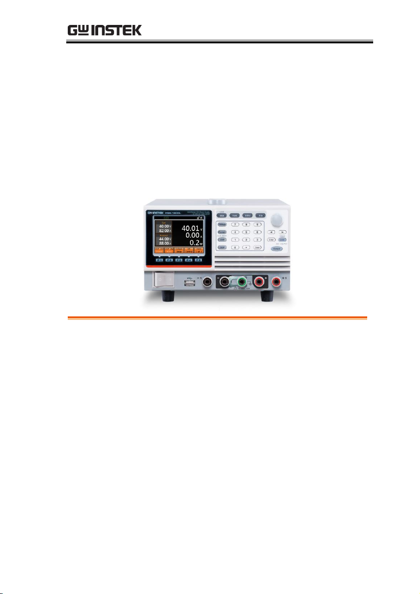
This chapter describes the power source in a
nutshell, including its main features and front /
rear panel introduction.
www.GlobalTestSupply.com
9

PSB-1000 Series User Manual
Alarms ....................................................................................................................... 34
Considerations .......................................................................................................... 36
Grounding ................................................................................................................ 39
10
www.GlobalTestSupply.com
GETTING STARTED
Model name
Output Voltage
Output Current
Output Power
PSB-1400L
40
40
400
PSB-1400M
160
10
400
PSB-1800L
40
80
800
PSB-1800M
160
20
800
PSB-1000 Series Overview
Series lineup
The PSB-1000 Series consists of 4 models: PSB-1400L, PSB-1400M,
PSB-1800L, and PSB-1800M. Note that throughout the user manual,
the term “PSB-1000” refers to all the models in the PSB-1000 Series
lineup, unless stated otherwise.
11
www.GlobalTestSupply.com

Main Features
Performance
Maximum output voltage of 160V
Maximum output current of 80A
Features
OVP, OCP and OTP protection
Low AC input protection
Sequence function
Large 3.5 inch LCD panel
100V - 240V power inlet
Multi-range output power
Bleeder circuit ON/OFF setting
CV, CC priority start function
Internal resistance setting function
Parallel master/slave operation with active
current sharing
Remote sensing to compensate for voltage drop
in load leads
Analog output programming and monitoring
Interface
Ethernet port
USB host
USB CDC
GPIB (optional)
External Control I/O
PSB-1000 Series User Manual
12
www.GlobalTestSupply.com
Accessories
Standard
Accessories
Part number
Description
CD ROM
User manual,
programming manual
Power cord
PSW-009
Output terminal cover
GTL-240
Type A - B USB Cable
PSB-106
Basic Accessory Kit:
M4 terminal screws and
washers x2, M8
terminal bolts, nuts and
washers x2, Analog
control protection
dummy x1, analog
control lock level x2,
short bar x1.
Optional
Accessories
Part number
Description
PSW-001
Analog remote control
connector kit:
Socket x 1pc
Pins x 10pcs
Protection cover x 1 set
Chassis connection wire
x 1
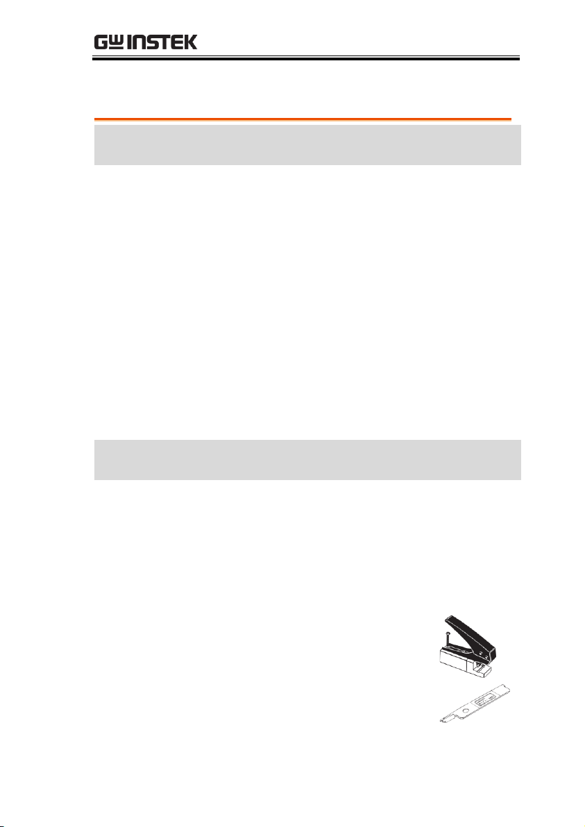
PSW-002
Simple IDC
tool
PSW-003
Contact
removal tool
GETTING STARTED
13
www.GlobalTestSupply.com

PSB-1000 Series User Manual
PSB-101
Cable for 2 units of PSB1000 units in parallel mode
connection
PSB-102
Cable for 3 units of PSB1000 units in parallel mode
connection
PSB-103
Cable for 4 units of PSB1000 units in parallel mode
connection
PSB-104
Cable for 2 units of PSB1000 units in series mode
connection
PSB-105
GPIB card
GRA-418-J
Rack-mount adapter(JIS)
GRA-418-E
Rack-mount adapter(EIA)
GTL-123
Test leads: 1x red, 1x black
Download
Name
Description
gw_psb1k.inf
USB driver
14
www.GlobalTestSupply.com
GETTING STARTED
0 - 160V , 10A
S S
F 1 F 2 F 3 F 4 F 5
PSB-1400M
0 - 160V / 0 - 10A , 400W
Multi-Range DC Power Supply
Main
FUNC
FileUtility
0
1
4
7
2
5
8
3
6
9
Voltage
Clear
Enter Lock
Output
Current
OVP
OCP
Local
CLR PROT. Unlock
: Long Push
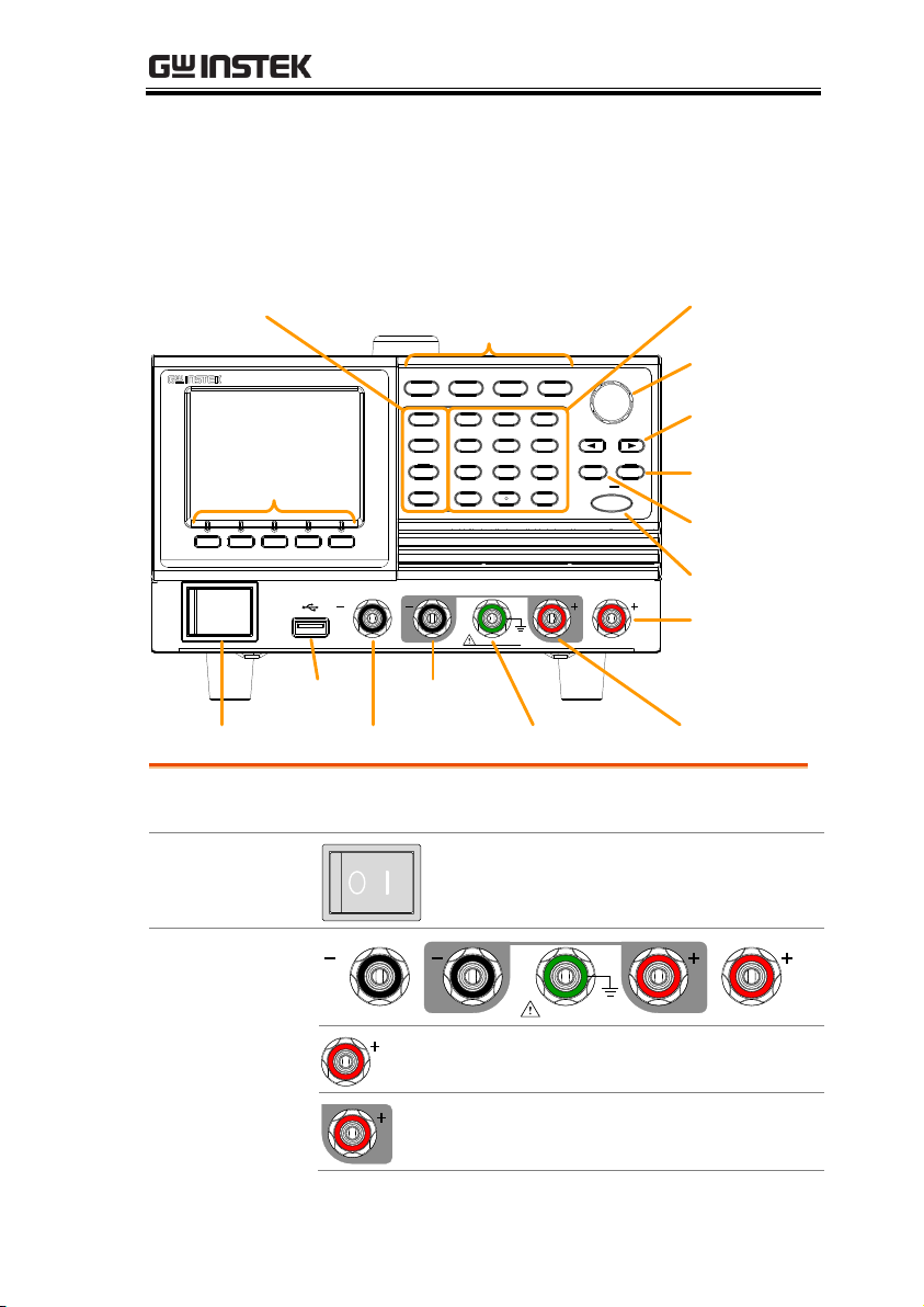
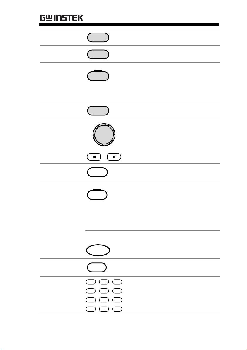
Power switch
LCD Display
Menu keys: Main/Local,
FUNC, Utility, File
Scroll wheel
Sense -
Arrow keys
Enter key
Lock/unlock
Output
F1~F5 soft-keys
USB A port - Terminal
Ground terminal + Terminal
Sense +
Number pad
Voltage, Current, OVP/
CLR PROT, OCP keys
Item
Description
Power Switch
Turns on the mains power.
Front Panel
Output Terminals
0 - 160V , 10A
S S
S
Positive sense terminal
Positive terminal
Appearance
Front Panel
www.GlobalTestSupply.com
15
PSB-1000 Series User Manual
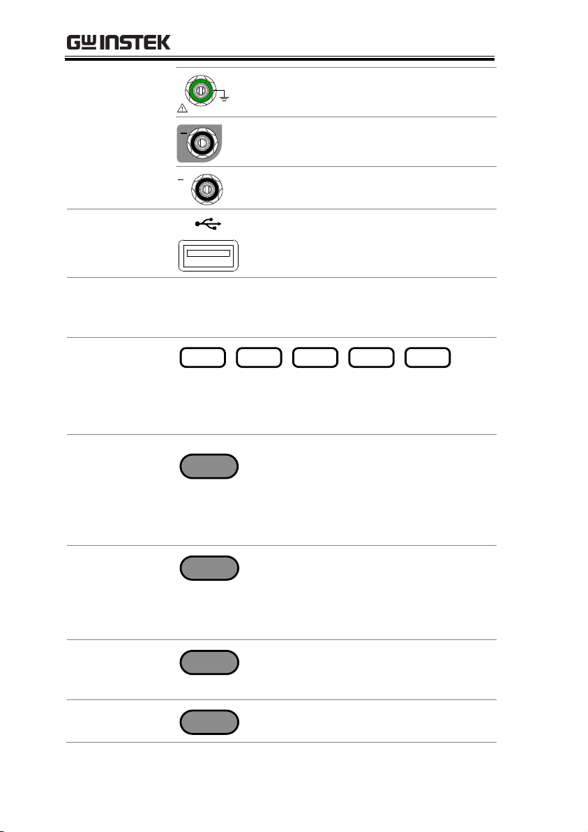
0 - 160V , 10A
Ground terminal
Negative terminal
S
Negative sense terminal
USB A Port
The USB port is used for data
transfer, loading test scripts etc.
LCD Screen
Displays the voltage/current
settings, measurement readings
and menu systems.
Function Keys
F 1 F 2 F 3 F 4 F 5
Assigned to the soft-keys
displayed on the bottom of the
screen.
Main Key
Main
Local
Returns operation to the main
operation screen.
Local Key
Pressing the Main/Local key will
also return the unit to local mode
from remote control mode.
FUNC Key
FUNC
Enters the Function menu. The
function menu contains Power On
Configuration settings, Memory
settings, Voltage trigger settings
and the Sequence menu.
Utility Key
Utility
Enters the Utility menu. The utility
menu contains a number of system
settings.
File Key
File
Pressing the file key allows you to
copy, rename and delete files.
16
www.GlobalTestSupply.com
GETTING STARTED
Voltage
Voltage
Sets the constant voltage level.
Current
Current
Sets the constant current level.
OVP
OVP
CLR PROT.
Sets the over voltage protection
level.
CLR PROT
(Long press)
Holding the OVP key will clear
any tripped protection functions.
OCP
OCP
Sets the over current protection
level.
Scroll Wheel &
Arrow Keys
Both the scroll wheel and arrow
keys are used to navigate menu
items, pages or for
incrementing/decrementing
parameter values.
Enter
Enter
Used to confirm settings and
menu items.
Lock Key/ Unlock
Key
Unlock
Lock
Locks the front panel keys to
prevent accidentally changing
panel settings.
Note: The output can still be
turned off when the key lock in
active.
Unlock Key
(Long press)
Disables the key lock.
Output Key
Output
Turns the output on or off.
Clear Key
Clear
Clears entries that are made in the
number entry dialogs.
Number Pad
7
4
1
0
8
5
2
Clear
3
6
9
Used to enter values.
www.GlobalTestSupply.com
17
PSB-1000 Series User Manual
TRIG IN
TRIG OUT
LAN
100 240V
1100VA MAX.
AC
47 63Hz
GPIB
SER. NO. LB
VOLT TRIG
LANVOLT TRIG
TRIG OUT
TRIG IN
Line input GPIB Option
USB BJ1 ConnectorRear panel terminals
Fans
TRIG IN
TRIG OUT
LAN
100 240V
550VA MAX.
AC
47 63Hz
GPIB
SER. NO. LB
VOLT TRIG
LANVOLT TRIG
TRIG OUT
TRIG IN
Line input GPIB Option
USB BJ1 ConnectorRear panel terminals
Fan
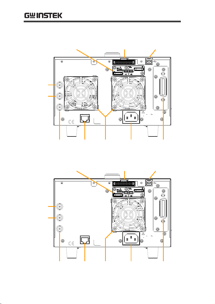
Rear Panel (PSB-1800L/M)
Rear Panel (PSB-1400L/M)
18
www.GlobalTestSupply.com
GETTING STARTED
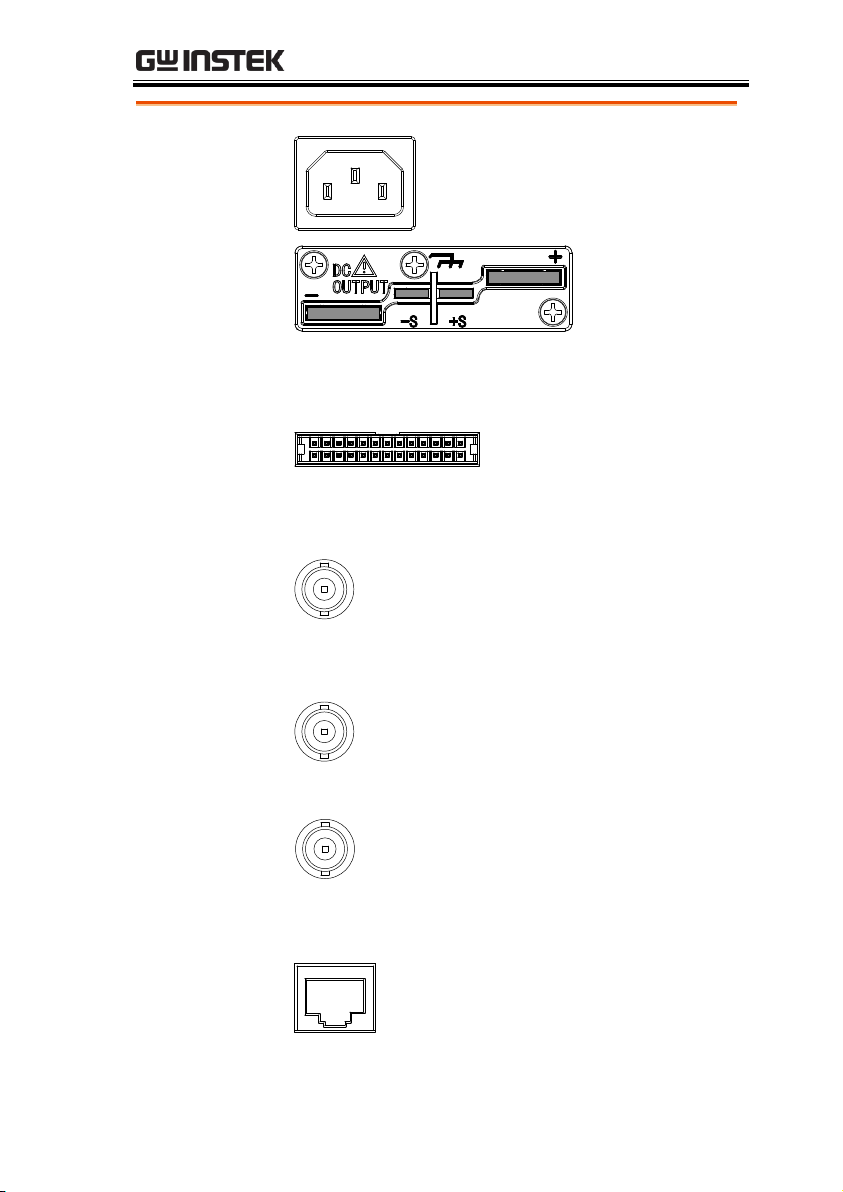
Line Voltage
Input
Voltage Input: 100 - 240 VAC
Line frequency: 47 - 63Hz (1100VA
MAX)
Rear panel
terminals
The rear panel terminals contain the positive and
negative output terminals, the voltage sense
terminals and the ground terminal.
J1 Connector
The J1 Connector is used
for external voltage,
current control or for
parallel/series control.
TRIG IN
TRIG IN
Used to receive a signal from an
external device.
Apply either a negative-going or a
positive-going pulse to the trigger
input pin.
TRIG OUT
TRIG OUT
Used to send a signal to an external
device.
The polarity of the trigger output
can also be configured.
VOLT TRIG
VOLT TRIG
Outputs a signal according to the
Voltage Trigger settings in the
Function menu.
The polarity of the voltage trigger
can also be configured.
LAN
LAN
The Ethernet port is used for remote
control and digital monitoring from
a PC.
www.GlobalTestSupply.com
19

PSB-1000 Series User Manual
USB-B
The USB-B port is used for remote
control.
GPIB Option
Optional GPIB communication card (PSB-105).
FAN
Temperature controlled fan.
20
www.GlobalTestSupply.com
GETTING STARTED
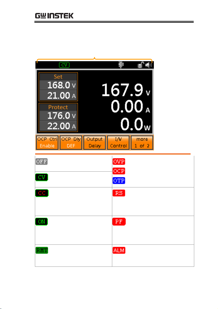
Status bar
Indicates if the output is
OFF.
An alarm icon will appear
on the status bar when one
of the protection functions
is tripped.
Indicates that the output
is in CV mode.
Indicates that the output
is in CC mode.
(Remote sense fail)
Indicates a problem with
the remote sense
connection.
Indicates that the output
is operating at 105% of
rated power (constant
power mode).
(Power fail) Indicates that
the external shutdown pin
was tripped.
Indicates that the unit is
in remote mode.
Indicates that the
instrument has hardware
errors.
Status Bar Icons
21
www.GlobalTestSupply.com
PSB-1000 Series User Manual
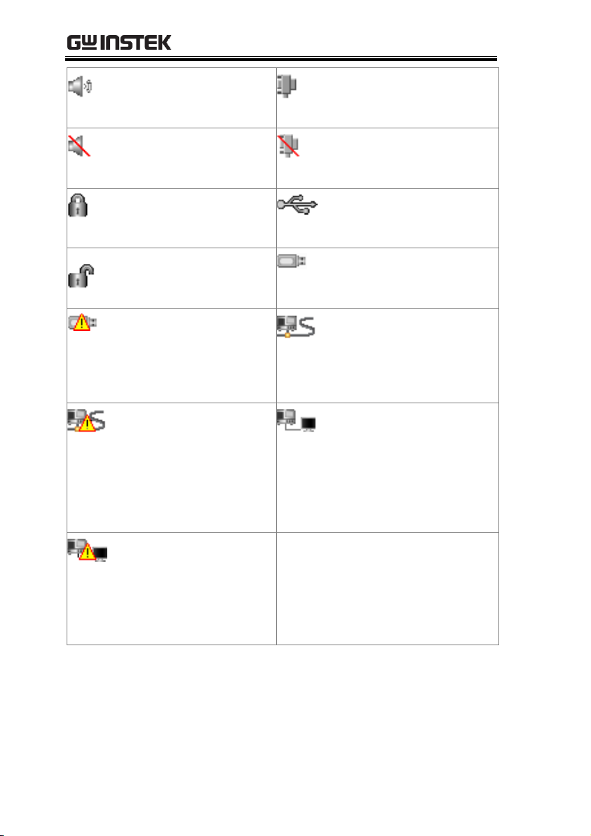
Speaker enabled.
Indicates that the GPIB
option is installed and
enabled.
Speaker disabled.
Indicates that the GPIB
option is installed and
disabled.
Indicates that the panel
lock is active.
Indicates that the
instrument is connected
with a PC.
Indicates that the panel
keys are unlocked.
Indicates that a USB flash
drive is inserted in the
front panel USB port.
Indicates that a USB
flash drive is inserted in
the front panel USB port,
but there is an access
error. Please re-insert.
Indicates that the
instrument is connected to
a LAN.
Indicates that the
instrument is connected
to a LAN, however,
there are configuration
errors. Please reconfigure the LAN
settings.
Indicates that the PSB-1000
is in LAN remote mode.
Indicates that the PSB1000 is in LAN remote
mode, but there are
connection errors. Please
re-configure the LAN
settings.
22
www.GlobalTestSupply.com
Level
Function/Operation
Description
1st
2nd
3rd
4th
Main
OCP Ctrl
Enables/Disables OCP
OCP Dly
Sets OCP delay time
Output
Delay
On Delay
Sets the Output On
delay time
Off Delay
Sets the Output Off
delay time.
I/V Control
CVHS
Sets the CV slew rate
to the maximum (High
Speed)
CCHS
Sets the CC slew rate
to the maximum (High
Speed)
CVLS
Sets the CV slew rate
CCLS
Sets the CC slew rate
Exit
Exits the I/V control
menu.
more 1 of
2
INT-R
Sets the internal
resistance.
Bleeder
Turns the bleeder
resistor on or off (of
auto).
Average
Sets the average level
for the smoothing
function (Low,
Middle, High)
More 2 of
2
Returns to the
previous page.
GETTING STARTED
Menu Reference
23
www.GlobalTestSupply.com
FUNC
View
Power On
Config.
Modify
CV Control
Sets CV control mode
CC Control
Sets CC control mode
PON Run
Sets the Power On
output settings (Turns
the output on or
executes a sequence at
start up)
Track
Sets the tracking mode
for multiple units
Ext-Out
Sets the Ext-Out line
active state
Breaker
Sets the breaker
resistor
Sense
Sets/disables local
sense
Exit
Exits from the View
Power On Config.
settings
View
Memory
M1
Shows the M1 settings
M2
Shows the M2 settings
M3
Shows the M3 settings
Exit
Exits the View
Memory menu.
Voltage
Trigger
Vtrig
Control
Enable/Disable
voltage trigger control
Vt1
Sets the leading edge
Vtrig level
Vt2
Sets the trailing edge
Vtrig level
Polarity
Sets the Vtrig polarity
as positive or negative
PSB-1000 Series User Manual
24
www.GlobalTestSupply.com
FUNC
(cont.)
TRIG IN
POS
Positive edge
NEG
Negative edge
Exit
Exits from the FUNC
menu.
TRIG OUT
POS
Positive edge
NEG
Negative edge
Exit
Exits from the FUNC
menu.
Sequence
Load
Loads the selected
sequence
Exit
Exits the sequence
menu
more 1 of
2
Copy to USB
Copies the selected
sequence to USB.
Copy to
SEQX
Copies the selected
sequence to another
sequence
Move to
SEQX
Move the selected
sequence to another
sequence
Clear
Clears the selected
sequence from the
memory
more 2 of 2
Returns to the
previous menu level
GETTING STARTED
25
www.GlobalTestSupply.com
Utility
System Information
Shows the serial
number and software
version
Interface
LAN
MAC
Address
Sets the MAC address
Host Name
Sets the host name
LAN Control
Enables/disables LAN
DHCP
Enables/disables
DHCP
Rear USB
Enables/disables USB
interface
GPIB
Enables/disables GPIB
interface
Error Log
LAN Log
Lists LAN errors
USB Log
Lists USB errors
GPIB Log
List GPIB errors
Clear
Clears the error logs
Exit
Exits to the previous
menu
Speaker
Enables/disables the
speaker
Lock
Mode0
Mode0 disables all
panel keys except the
ability to turn the load
off.
Mode1
Mode1 disables all
panel keys except the
ability to turn the load
on or off.
PSB-1000 Series User Manual
26
www.GlobalTestSupply.com
GETTING STARTED
Utility
(cont.)
Color
Brightness
Sets the brightness
level
Contrast
Sets the contrast level
Default
Default
brightness/contrast
settings
Exit
Exits to the previous
menu
Factory
Setting
Restore
Restore the factory
settings
Exit
Exits to the previous
menu
Calibration
Not applicable to endusers.
File
Copy to
USB
Copy the selected file
to USB
Copy to
Mx
Copy the selected file
to memory location
M0~9.
Save
Saves the current
settings to the selected
memory setting.
Recall
Recalls the selected
memory setting.
View
Memory
Goes to the View
Memory menu.
Copy to
memory
Copies the selected file
on the USB drive to
memory.
Delete
Deletes the selected
file on the USB drive.
Rename
Renames the selected
file on the USB drive.
27
www.GlobalTestSupply.com

PSB-1000 Series User Manual
Voltage
Sets the voltage output
settings
Current
Sets the current output
settings
OVP
Sets the OVP settings
OCP
Sets the OCP settings
28
www.GlobalTestSupply.com
GETTING STARTED
Background
The PSB-1000 power supplies are regulated DC
power supplies with a high voltage and current
output. These operate in CC or CV mode
within a wide operating range limited only by
the voltage, current or power output.
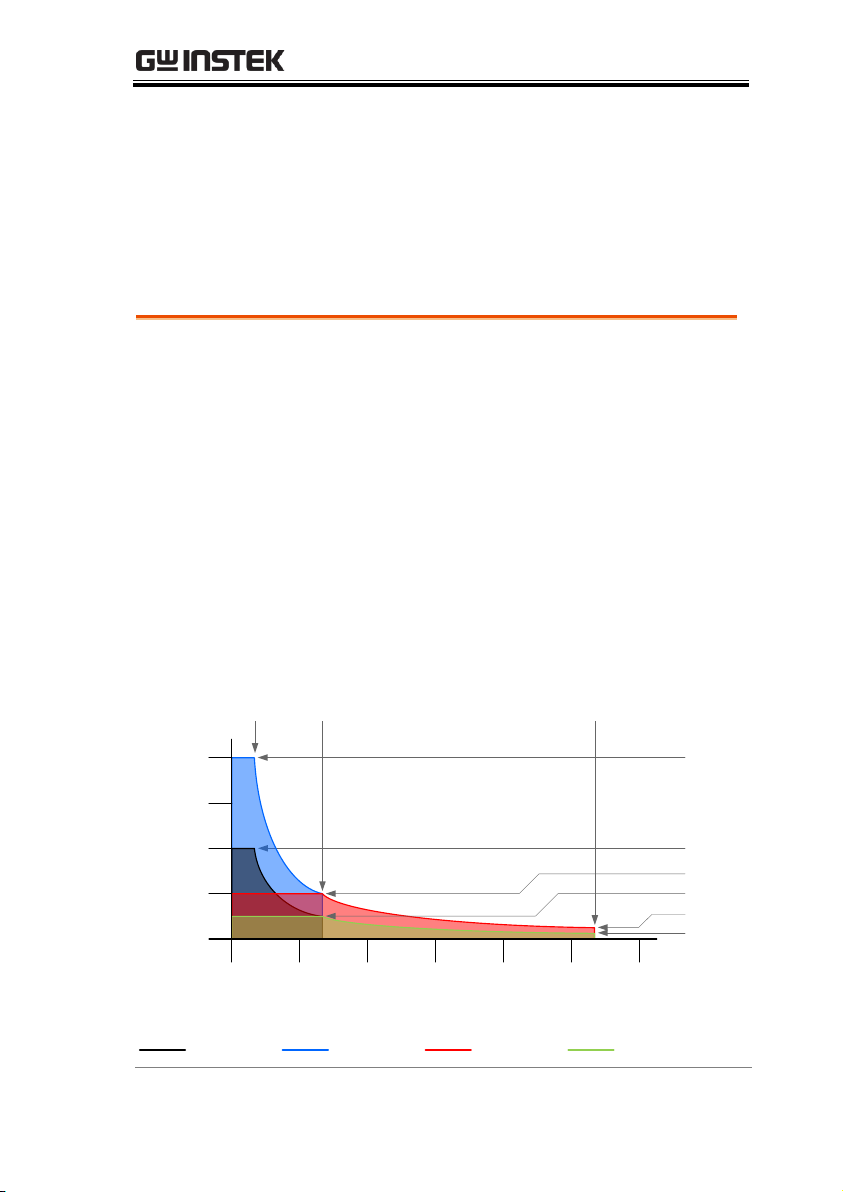
The operating area of each power supply is
determined by the rated output power as well
as the voltage and current rating.
Below is a comparison of the operating areas of
each power supply.
Voltage (V)
10 40
160
80
40
5
2.5
PSB-1000 Series Output Operating Area
PSB-1400MPSB-1800MPSB-1800LPSB-1400L
0
30
60
90
120 150
180
Current (A)
0
20
40
60
80
10
20
Theory of Operation
The theory of operation section describes the basic principles of
operation, protection modes and important considerations that
must be taken into account before use.
Operating Area Description
www.GlobalTestSupply.com
29

PSB-1000 Series User Manual
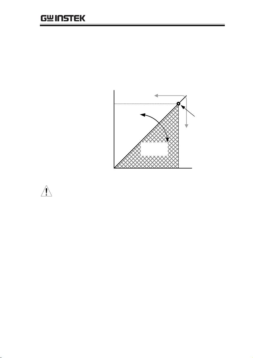
CC and CV mode
Description
When the power supply is operating in
constant current mode (CC) a constant current
will be supplied to the load. When in constant
current mode the voltage output can vary,
whilst the current remains constant. When the
load resistance increases to the point where the
set current limit (I
SET
) can no longer be
sustained the power supply switches to CV
mode. The point where the power supply
switches modes is the crossover point.
When the power supply is operating in CV
mode, a constant voltage will be supplied to
the load, whilst the current will vary as the
load varies. At the point that the load
resistance is too low to maintain a constant
voltage, the power supply will switch to CC
mode and maintain the set current limit.
The conditions that determine whether the
power supply operates in CC or CV mode
depends on the set current (I
SET
), the set voltage
(V
SET
), the load resistance (RL) and the critical
resistance (RC). The critical resistance is
determined by V
SET/ISET
. The power supply
will operate in CV mode when the load
resistance is greater than the critical resistance.
This means that the voltage output will be
equal to the V
SET
voltage but the current will be
less than I
SET
. If the load resistance is reduced
to the point that the current output reaches the
I
SET
level, the power supply switches to CC
mode.
CC and CV Mode
30
www.GlobalTestSupply.com
GETTING STARTED
Conversely the power supply will operate in
CC mode when the load resistance is less than
the critical resistance. In CC mode the current
output is equal to I
SET
and the voltage output is
less than V
SET
.
RL=R
C
RL<R
C
VSET
ISET
CV
CC
V
I
RL>R
C
Crossover
point
Note
For loads that generate a transient surge voltage,
VSET must be set so that the surge voltage does
not reach the voltage limit.
For loads in which transient peak current flows,
ISET must be set so that the peak value does not
reach the current limit.
www.GlobalTestSupply.com
31
 Loading...