

GW Instek PSB-1400M, PSB-1400L, PSB-1000 series, PSB-1800L, PSB-1800M Quick Start Manual

Multi-Range DC Power Supply
PSB-1000 Series
QUICK START GUIDE
GW INSTEK PART NO. 82SB-18000M01
ISO-9001 CERTIFIED MANUFACTURER

This manual contains proprietary information, which is
protected by copyright. All rights are reserved. No part
of this manual may be photocopied, reproduced or
translated to another language without prior written
consent of Good Will Corporation.
The information in this manual was correct at the time
of printing. However, Good Will continues to improve
its products and therefore reserves the right to change
the specifications, equipment, and maintenance
procedures at any time without notice.
Good Will Instrument Co., Ltd. No. 7-1, Jhongsing Rd., Tucheng
Dist., New Taipei City 236, Taiwan.
1
SAFETY INSTRUCTIONS
This section contains the basic safety symbols that may
appear on the accompanying User Manual CD or on the
instrument. For detailed safety instructions and
precautions, please see the Safety Instructions chapter
in the user manual CD.
Safety Symbols
These safety symbols may appear in the user manual or
on the instrument.
Warning
Warning: Identifies conditions or
practices that could result in injury or
loss of life.
Caution
Caution: Identifies conditions or
practices that could result in damage
to the PSB-1000 or to other properties.
DANGER High Voltage
Attention Refer to the Manual
Protective Conductor Terminal
Earth (ground) Terminal
Do not dispose electronic equipment
as unsorted municipal waste. Please
use a separate collection facility or
contact the supplier from which this
instrument was purchased.
2
Power Cord for the United Kingdom
When using the instrument in the United Kingdom,
make sure the power cord meets the following safety
instructions.
NOTE: This lead/appliance must only be wired by
competent persons.
WARNING: THIS APPLIANCE MUST BE EARTHED
IMPORTANT: The wires in this lead are coloured in
accordance with the following code:
Green/ Yellow:
Earth
Blue:
Neutral
Brown:
Live (Phase)
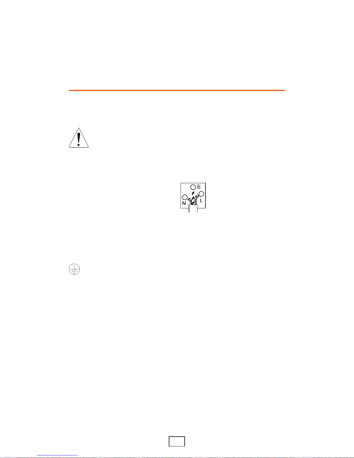
As the colours of the wires in main leads may not correspond with
the coloured marking identified in your plug/appliance, proceed as
follows:
The wire which is coloured Green & Yellow must be connected to
the Earth terminal marked with either the letter E, the earth symbol
or coloured Green/Green & Yellow.
The wire which is coloured Blue must be connected to the terminal
which is marked with the letter N or coloured Blue or Black.
The wire which is coloured Brown must be connected to the terminal
marked with the letter L or P or coloured Brown or Red.
If in doubt, consult the instructions provided with the equipment or
contact the supplier.
This cable/appliance should be protected by a suitably rated and
approved HBC mains fuse: refer to the rating information on the
equipment and/or user instructions for details. As a guide, a cable of
0.75mm2 should be protected by a 3A or 5A fuse. Larger conductors
would normally require 13A types, depending on the connection
method used.
Any exposed wiring from a cable, plug or connection that is engaged
in a live socket is extremely hazardous. If a cable or plug is deemed
hazardous, turn off the mains power and remove the cable, any
fuses and fuse assemblies. All hazardous wiring must be
immediately destroyed and replaced in accordance to the above
standard.
3
GETTING STARTED
The Getting Started chapter describes the power source
in a nutshell, including its main features and front/rear
panel introduction.
Overview
The PSB-1000 Series consists of 4 models: PSB-1400L,
PSB-1400M, PSB-1800L, and PSB-1800M. Note that
throughout the user manual, the term “PSB-1000” refers
to all the models in the PSB-1000 Series lineup, unless
stated otherwise.
Model Line Up
Model name
Output
Voltage
Output
Current
Output Power
PSB-1400L
40
40
400
PSB-1400M
160
10
400
PSB-1800L
40
80
800
PSB-1800M
160
20
800
Main Features
Performance
• Maximum output voltage of 160V
• Maximum output current of 80A
4
Features
• OVP, OCP and OTP protection
• Low AC input protection
• Sequence function
• Large 3.5 inch LCD panel
• 100V - 240V power inlet
• Multi-range output power
• Bleeder circuit ON/OFF setting
• CV, CC priority start function
• Internal resistance setting
function
• Parallel master/slave operation
with active current sharing
• Remote sensing to compensate for
voltage drop in load leads
• Analog output programming and
monitoring
Interface
• Ethernet port
• USB host
• USB CDC
• GPIB (optional)
• External Control I/O
Accessories
Standard Accessories
Item
Part Number
User manual, programming manual
CD ROM
Power cord
Output terminal cover
PSW-009
Type A - B USB Cable
GTL-240
Continued on the next page...
 Loading...