


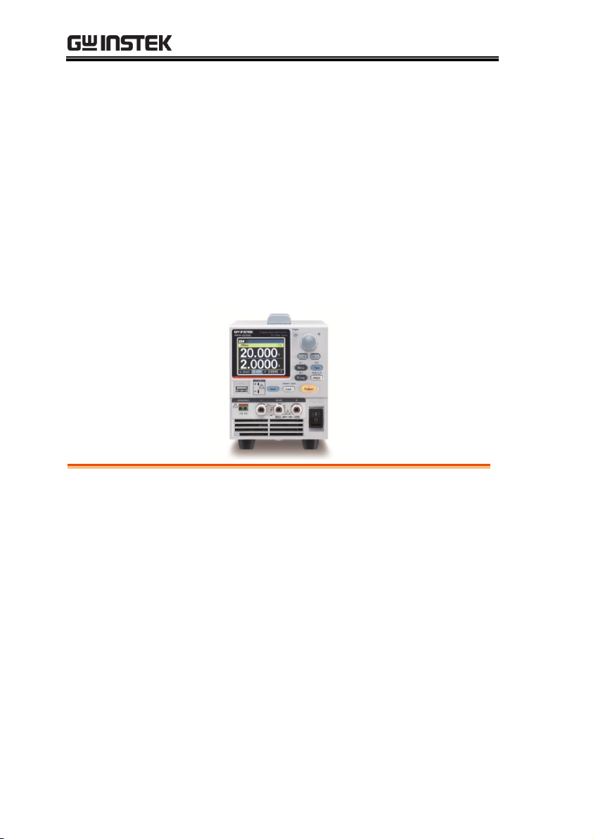
Programmable High Precision DC
Power Supply
PPX Series
USER MANUAL
Rev. A
ISO-9001 CERTIFIED MANUFACTURER

This manual contains proprietary information, which is protected by
copyright. All rights are reserved. No part of this manual may be
photocopied, reproduced or translated to another language without
prior written consent of Good Will company.
The information in this manual was correct at the time of printing.
However, Good Will continues to improve products and reserves the
rights to change specification, equipment, and maintenance
procedures at any time without notice.
Good Will Instrument Co., Ltd.
No. 7-1, Jhongsing Rd., Tucheng Dist., New Taipei City 236, Taiwan.

TABLE OF CONTENTS
Table of Contents
SAFETY INSTRUCTIONS .................................................. 5
GETTING STARTED .......................................................... 8
PPX Series Overview .............................. 9
Appearance .......................................... 12
Theory of Operation ............................. 20
OPERATION .................................................................. 30
Set Up .................................................. 31
Menu Tree ............................................ 40
Basic Operation ................................... 46
Sequence Test ...................................... 74
MENU CONFIGURATION .............................................. 107
Configuration Overview ..................... 108
Output ............................................... 108
Measurement ..................................... 112
EXT Control ....................................... 115
TRIG Control ...................................... 120
PWR On Config .................................. 126
Constant PWR .................................... 127
Temperature....................................... 130
Save/Recall ........................................ 134
Interface ............................................ 137
Utility ................................................. 144
APP .................................................... 152
Calibration ......................................... 155
ANALOG CONTROL ...................................................... 156
Analog Remote Control Overview ....... 157
Remote Monitoring ............................ 173
3

PPX Series User Manual
COMMUNICATION INTERFACE .................................... 178
Interface Configuration ...................... 179
FAQ .............................................................................. 208
APPENDIX .................................................................... 210
PPX Factory Default Settings .............. 210
PPX Specifications ............................. 213
PPX Dimensions ................................ 218
Declaration of Conformity .................. 219
INDEX .......................................................................... 220
4

SAFETY INSTRUCTIONS
WARNING
Warning: Identifies conditions or practices that
could result in injury or loss of life.
CAUTION
Caution: Identifies conditions or practices that
could result in damage to the PPX or to other
properties.
DANGER High Voltage
Attention Refer to the Manual
Protective Conductor Terminal
Earth (ground) Terminal
SAFETY INSTRUCTIONS
This chapter contains important safety
instructions that you must follow during
operation and storage. Read the following before
any operation to insure your safety and to keep
the instrument in the best possible condition.
Safety Symbols
These safety symbols may appear in this manual or on the
instrument.
5
PPX Series User Manual
Do not dispose electronic equipment as unsorted
municipal waste. Please use a separate collection
facility or contact the supplier from which this
instrument was purchased.
General
Guideline
CAUTION
Do not place any heavy object on the PPX.
Avoid severe impact or rough handling that
leads to damaging the PPX.
Do not discharge static electricity to the PPX.
Use only mating connectors, not bare wires, for
the terminals.
Do not disassemble the PPX unless you are
qualified.
Power Supply
CAUTION
WARNING
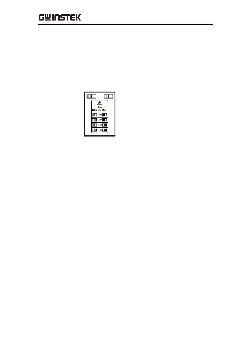
AC Input Voltage:
100Vac/120Vac/220Vac/240Vac, 50Hz/60Hz,
single phase
Frequency: 47Hz to 63Hz
Before connecting the power plug to an AC line
outlet, make sure the voltage selector switches
of the bottom panel in the correct position.
Disconnect power cord and test leads before
replacing fuse.
The fuse specification is as following:
To avoid electrical shock connect the protective
grounding conductor of the AC power cord to
an earth ground.
Safety Guidelines
6

SAFETY INSTRUCTIONS
Cleaning the PPX
Disconnect the power cord before cleaning.
Use a soft cloth dampened in a solution of mild
detergent and water. Do not spray any liquid.
Do not use chemicals containing harsh material
such as benzene, toluene, xylene, and acetone.
Operation
Environment
Location: Indoor, no direct sunlight, dust free,
almost non-conductive pollution (Note below)
Relative Humidity: 20%~ 80% (no condensation)
Altitude: < 2000m
Temperature: 0°C to 40°C
(Pollution Degree) EN61010-1:2010 specifies the pollution degrees
and their requirements as follows. The PPX falls under degree 2.
Pollution refers to “addition of foreign matter, solid, liquid, or
gaseous (ionized gases), that may produce a reduction of dielectric
strength or surface resistivity”.
Pollution degree 1: No pollution or only dry, non-conductive
pollution occurs. The pollution has no influence.
Pollution degree 2: Normally only non-conductive pollution
occurs. Occasionally, however, a temporary conductivity caused
by condensation must be expected.
Pollution degree 3: Conductive pollution occurs, or dry, non-
conductive pollution occurs which becomes conductive due to
condensation which is expected. In such conditions, equipment
is normally protected against exposure to direct sunlight,
precipitation, and full wind pressure, but neither temperature
nor humidity is controlled.
Storage
environment
Location: Indoor
Temperature: -20°C to 70°C
Relative Humidity: 20 to 85%(no condensation)
Disposal
Do not dispose this instrument as unsorted
municipal waste. Please use a separate collection
facility or contact the supplier from which this
instrument was purchased. Please make sure
discarded electrical waste is properly recycled to
reduce environmental impact.
7
PPX Series User Manual
PPX Series Overview .............................................. 9
Series lineup ........................................................................................ 9
Main Features ..................................................................................... 9
Accessories ........................................................................................10
Appearance .......................................................... 12
Front Panel ........................................................................................12
Display Area ......................................................................................16
Rear Panel ..........................................................................................18
Theory of Operation ............................................. 20
Operating Description ....................................................................20
CC and CV Mode.............................................................................21
Slew Rate ...........................................................................................22
Bleeder Control ................................................................................23
Alarms ................................................................................................24
Considerations ..................................................................................25
Grounding .........................................................................................28
GETTING STARTED
This chapter describes the power supply in a
nutshell, including its main features and front /
rear panel introduction. After going through the
overview, please read the theory of operation to
become familiar with the operating modes,
protection modes and other safety considerations.
8

GETTING STARTED
Model name
Operation Voltage
Operation Current
Rated Power
PPX-1005
0-10V
0-5A
50W
PPX-2002
0-20V
0-2A
40W
PPX-2005
0-20V
0-5A
100W
PPX-3601
0-36V
0-1A
36W
PPX-3603
0-36V
0-3A
108W
PPX-10H01
0-100V
0-1A
100W
Features
2.4" TFT-LCD Panel.
Preset memory function.
Output ON/OFF delay function.
CV, CC priority start function. (prevents
overshoot with output ON)
Adjustable voltage and current slew rates.
Bleeder circuit ON/OFF setting. (to prevent
over-discharging of batteries)
OVP, OCP, AC Alarm and OTP protection.
Supports test sequence.
Web server monitoring and control. (The
function is activated when connecting to LAN
Interface)
Analog monitor output.
PPX Series Overview
Series lineup
The PPX series consists of 6 models, covering a number of different
current, voltage and power capacities:
Main Features
9

PPX Series User Manual
Remote sensing to compensate for voltage drop
in load leads.
Support K type thermocouple temperature
measurement.
With 4 measuring currents and Manual / Auto
shift function.
Interface
Built-in USB, RS-232/485 and LAN interface.
External analog control function.
Optional GPIB interface.
Standard
Accessories
Part number
Description
Qty.
GTL-104A
Test leads for PPX-1005/PPX2005/PPX-3603 (Binding Posts
Terminal), 1m, 10A
1
GTL-105A
Test leads for PPX-2002/PPX-3601,
1m, 3A
1
Short Bar (Binding Posts Terminal)
1
GTL-204A
Test leads for PPX-1005/PPX2005/PPX-3603 (European Type Jack
Terminal), 1m, 10A
1
GTL-203A
Test leads for PPX-2002/PPX3601/PPX-10H01 (European Type Jack
Terminal), 1m, 3A
1
GTL-201A
Ground lead for European Type Jack
Terminal
1
Power Cord
1
Accessories
Before using the PPX power supply unit, check the package
contents to make sure all the standard accessories are included.
10

GETTING STARTED
Optional
Accessories
Part number
Description
GRA-441-J
Rack for PPX (JIS)
GRA-441-E
Rack for PPX (EIA)
GTL-205A
Temperature probe adaptor with
thermocouple K type
GTL-246
USB Cable (USB 2.0 Type A- Type B Cable,
4P)
GTL-258
GPIB Cable, 2000mm
GTL-259
RS232 cable with DB9 connector to RJ45
GTL-260
RS485 cable with DB9 connector to RJ45
GTL-262
RS485 slave cable
Factory Installed
Options
Part number
Description
Option 1
GPIB interface
11
1
2
3
4
5
6
7
8
9
10
11
12
14
15
13
16
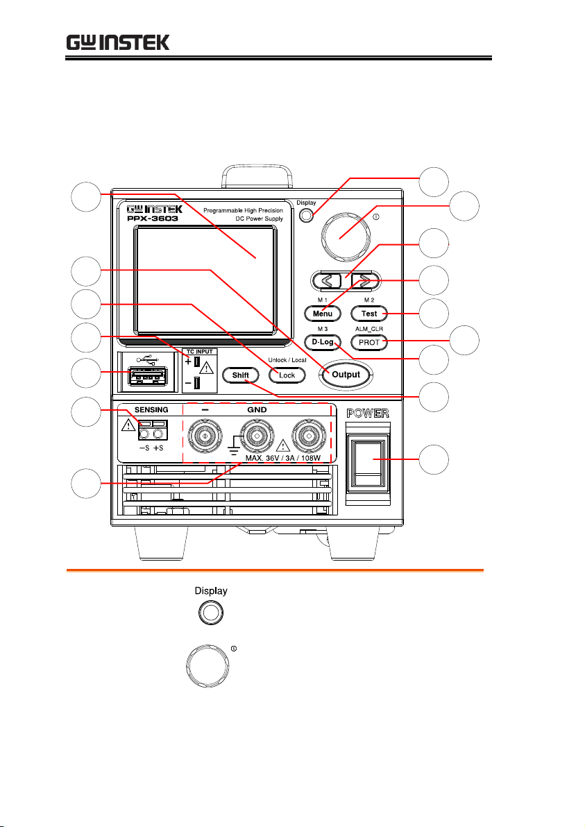
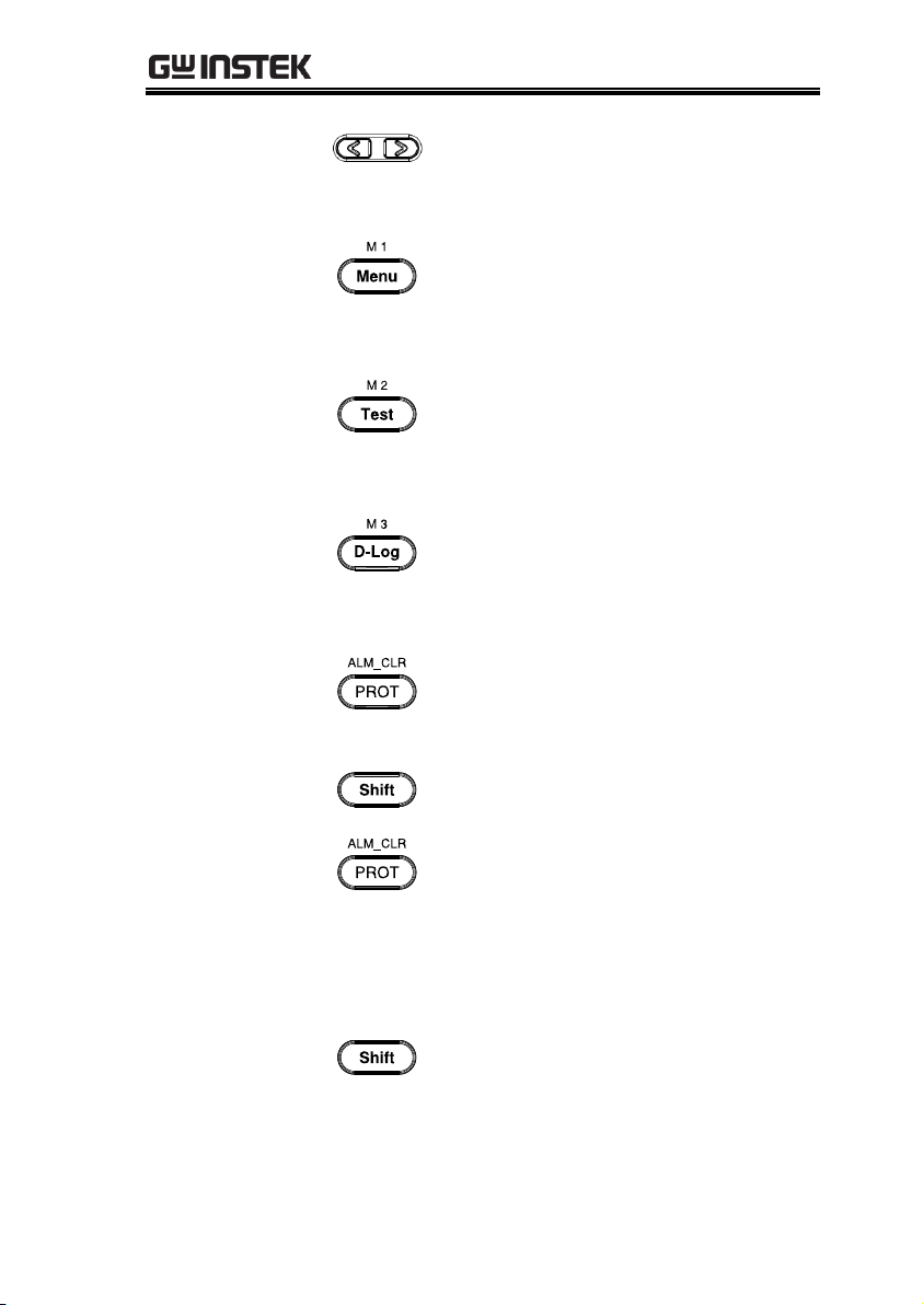
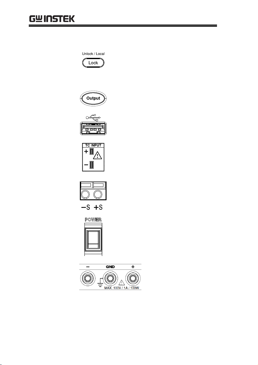
1.
Display
Button
Used to switch among 4 different
display modes.
2.
Knob Key
Used to navigate menu, and to
configure or confirm
voltage/current/time values, among
others. Also, the indicator on the
upper-right corner shows current state
and power mode.
PPX Series User Manual
Appearance
Front Panel
12
GETTING STARTED
3.
Left/Right
Arrow Keys
Used to select a parameter number in
the Function settings. Also the left
arrow key can be used as backspace.
4.
Menu Button
Used to enter the Menu page. Refer to
page 108 for detail.
M1 Button
(+Shift) Used to recall the M1 setup.
5.
Test Button
Used to run customized test sequence.
Refer to page 74 for detail.
M2 Button
(+Shift) Used to recall the M2 setup.
6.
D-Log Button
Used to run data log function. Refer to
page 71 for detail.
M3 Button
(+Shift) Used to recall the M3 setup.
7. PROT Button
Used to set OVP, OCP and UVL
protecting functions. Refer to page 47
for details.
ALM_CLR
Button
+
(+Shift) Used to release protection
functions that have been activated.
The tripped protection alarms include
the following: OVP Alarm, OCP
Alarm, OTP Alarm, AC Alarm, Sense
Alarm, WDOG Alarm, Ah CAP
Alarm, Wh CAP Alarm, TEMP Short
Alarm, TEMP Monitor Alarm.
8.
Shift Button
Used to enable the functions that are
written in blue characters above
certain buttons.
13
PPX Series User Manual
9.
Lock Button
Used to lock all front panel buttons
other than the Output Button. Refer to
page 60 for detail.
Unlock/Local
Button
(+Shift) Used to unlock the front panel
buttons or it switches to local mode.
10.
Output
Button
Used to turn the output on or off.
11.
USB A Port
USB A port for data transfer, loading
test scripts and firmware update.
12.
TC Input
Terminal to connect the K type
thermocouple cable for temperature
measurement. Refer to page 66 for
detail.
13.
Sensing
Terminal
Terminal to connect the sensing
cables, which compensate voltage
drop occurred in load leads.
14.
Power Switch
Used to turn the power on/off.
15.
Output
terminal
DC output terminal for
PPX is European Type
Jack Terminal.
PPX-10H01 the max.
output is 100V/1A/100W
14
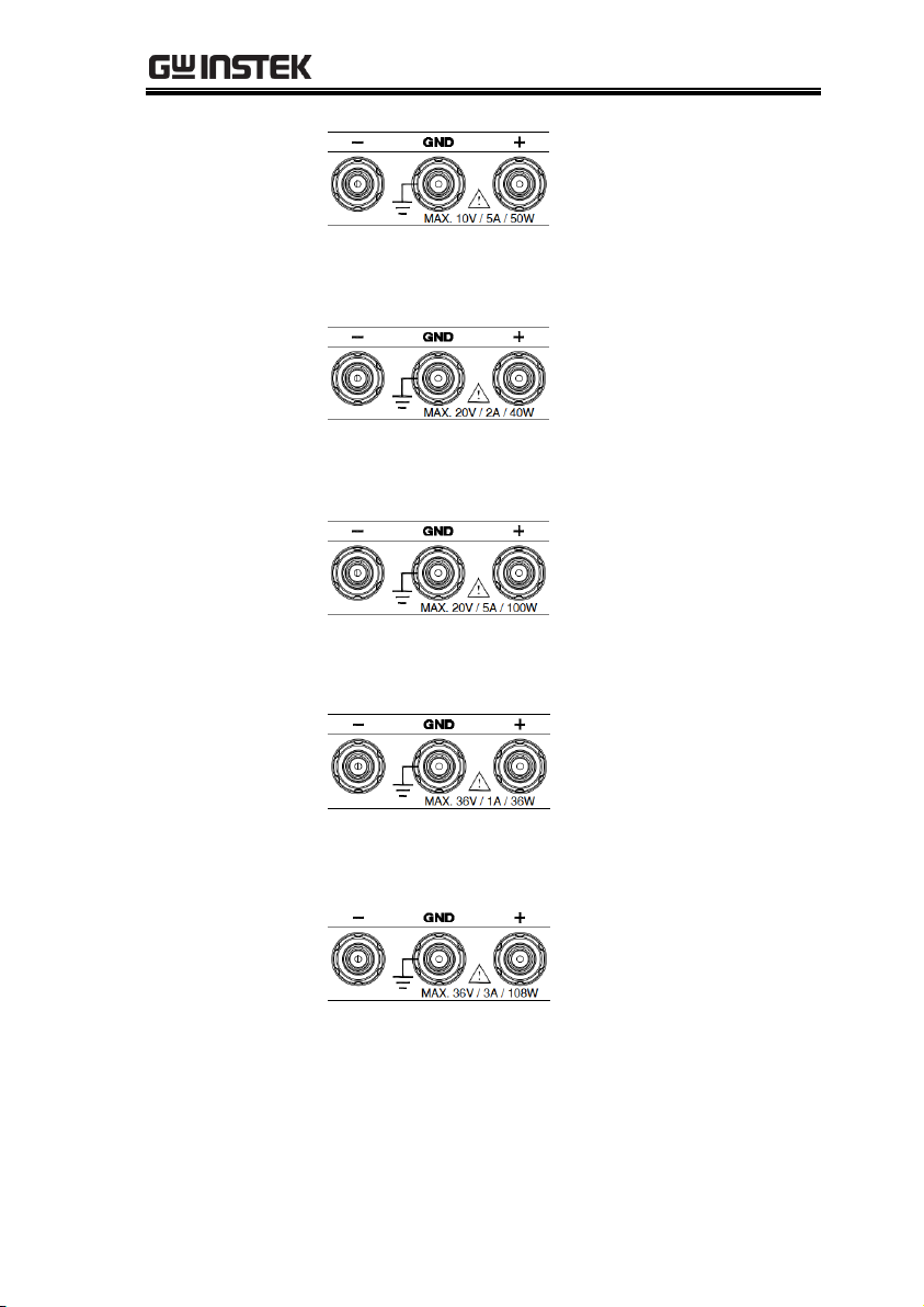
GETTING STARTED
DC output terminal for
PPX is Binding Posts
Terminal or European
Type Jack Terminal.
PPX-1005 the max. output
is 10V/5A/50W
DC output terminal for
PPX is Binding Posts
Terminal or European
Type Jack Terminal.
PPX-2002 the max. output
is 20V/2A/40W
DC output terminal for
PPX is Binding Posts
Terminal or European
Type Jack Terminal.
PPX-2005 the max. output
is 20V/5A/100W
DC output terminal for
PPX is Binding Posts
Terminal or European
Type Jack Terminal.
PPX-3601 the max. output
is 36V/1A/36W
DC output terminal for
PPX is Binding Posts
Terminal or European
Type Jack Terminal.
PPX-3603 the max. output
is 36V/3A/108W
16
Display Area
The display area shows set values, output values
and parameter settings.
15
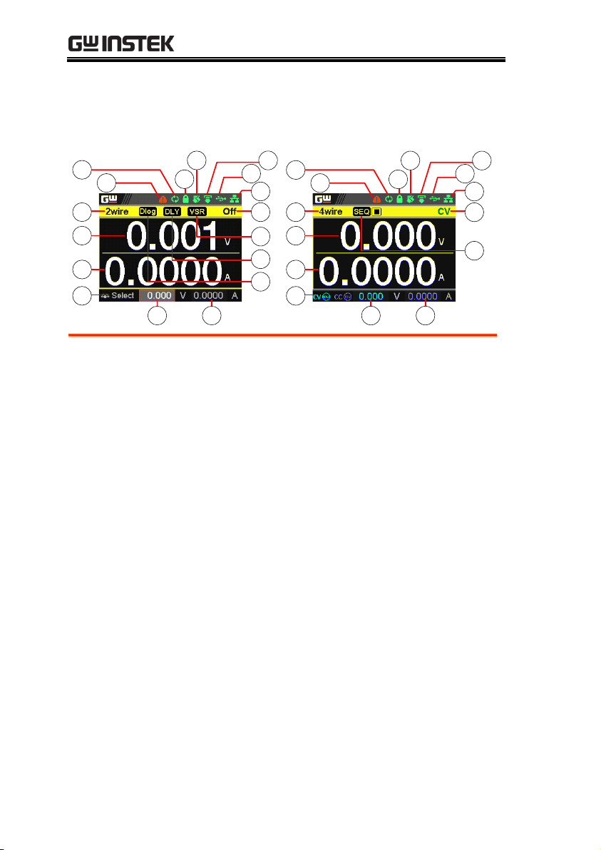
Display Area
1
2
3
4
5 6
7
8
9
10
17
16
15
14 12
13
11
1
2
3
4
5 6
7
10
17
16
15
14 12
13
11
1.
2Wire/4Wire
2-wire or 4-wire indicator.
2.
Voltage Meter
Displays the voltage.
3.
Current Meter
Displays the current.
4.
V/A Set
Guidance
The scrolling symbol indicates to select
between V and A set via scrolling knob key.
External CC &
CV Control
When the external CC or CV control is
activated, the indicator(s) will be shown.
5.
V Set
Manually sets voltage.
6.
I(A) Set
Manually sets current.
7.
Dlog Icon
When Data Logger is enabled, the icon will be
shown accordingly. Note that when SEQ
appears, the icon will be faded out.
SEQ
When Sequence function is turned On, the icon
will be shown accordingly.
PPX Series User Manual
16

GETTING STARTED
8.
DLY Icon
When Output On/Off Dly is enabled, the icon
will be shown accordingly. Note that when
SEQ appears, the icon will be faded out.
9.
VSR/ISR
Icon
When CV/CC Slew Rate Priority (CVLS/CCLS)
is activated, the icon will be shown. Note that
when SEQ appears, the icon will be faded out.
10.
CC/CV/UR
indicator
It shows when constant voltage or constant
current mode is ongoing. However, when output
is unregulated, which means neither in CV mode
nor CC mode, it shows UR instead. If it is not
under power output, it simply shows Off.
11.
LAN Indicator
When PPX series connects to LAN network, the
icon will be shown.
12.
Remote Control
Indicator
When remote control (USB/LAN/GPIB,
UART) is underway, the icon will be shown.
13.
USB Indicator
When USB disk is inserted into the front panel
of PPX series, the icon will be shown.
14.
External Output
Indicator
When external output enable is turned On, the
icon will be shown.
15.
Lock Indicator
When the lock mode is activated, the icon will
be shown.
16.
Communication
Monitor
Indicator
When communication monitor is enabled, the
icon will be shown.
17.
Error Indicator
When error occurs from command of remote
control, the icon will be shown.
17
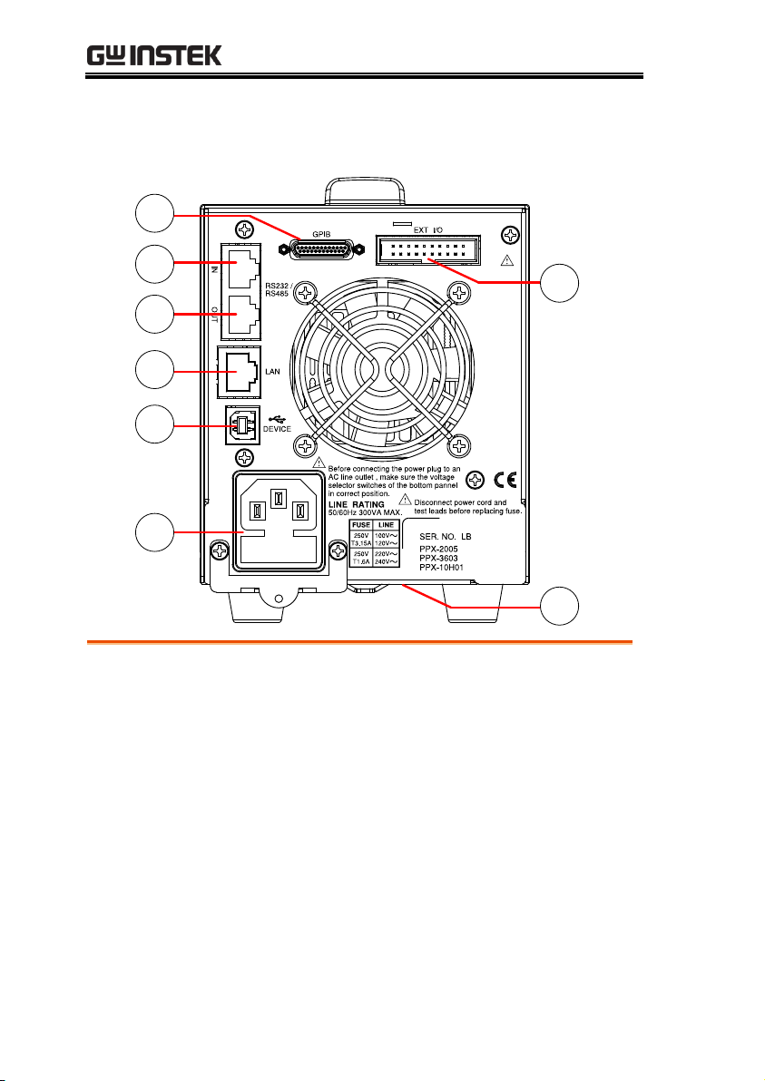
Rear Panel
5
2
1
3
4
6
7
8
1.
Remote-OUT
RJ-45 connector that is used to daisy chain power
supplies with the Remote-IN port to form a
communication bus.
2.
Remote-IN
Two different types of cables can be used for
RS232 or RS485-based remote control.
PSU-232: RS232 cable with DB9 connector kit.
PSU-485: RS485 cable with DB9 connector kit.
3.
LAN
Ethernet port for controlling the PPX remotely
4.
USB
USB port for controlling the PPX remotely.
PPX Series User Manual
18
GETTING STARTED
5.
GPIB
GPIB connector for units equipped with IEEE
programming option. (Factory Installed Options)
6.
EXT I/O
External analog remote control connector.
7.
Line Voltage
Input
AC inlet.
8.
AC Select
Switch
The AC selector is located at the
bottom side of the unit.
Switch Voltage to 100V, 120V,
220V or 240V.
19

PPX Series User Manual
Background
The PPX power supplies are regulated DC
power supplies with a stable voltage and
current output. These operate within a switch
automatically between constant voltage and
constant current according to changes in the
load.
Suitable supply cord set for use with the equipment:
Mains plug: shall be national approval
Mains connector: C13 type
Cable:
1. Length of power supply cord: less
than 3m
2. Cross-section of conductors: at least
0.75mm2
3. Cord type: shall meet the
requirements of IEC 60227 or IEC
60245 (e.g.: H05VV-F, H05RN-F)
Caution
If the equipment is used in a manner not specified
by the manufacturer, the protection provided by
the equipment may be impaired.
Theory of Operation
The theory of operation chapter describes the basic principles of
operation, protection modes and important considerations that
must be taken into account before use.
Operating Description
20

GETTING STARTED
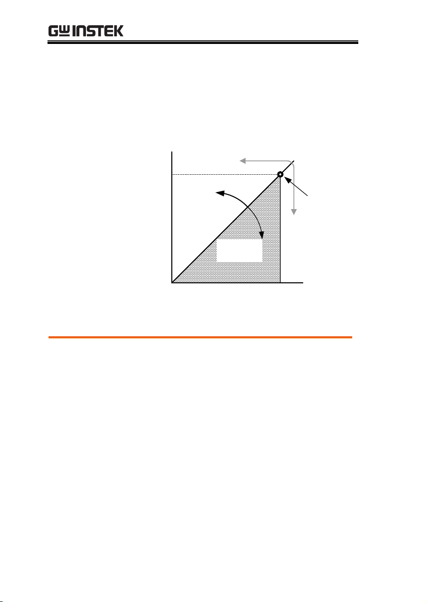
CC and CV mode
Description
When the power supply is operating in
constant current mode (CC) a constant current
will be supplied to the load. When in constant
current mode the voltage output can vary,
whilst the current remains constant. When the
load resistance increases to the point where the
set current limit (I
SET
) can no longer be
sustained the power supply switches to CV
mode. The point where the power supply
switches modes is the crossover point.
When the power supply is operating in CV
mode, a constant voltage will be supplied to
the load, whilst the current will vary as the
load varies. At the point that the load
resistance is too low to maintain a constant
voltage, the power supply will switch to CC
mode and maintain the set current limit.
The conditions that determine whether the
power supply operates in CC or CV (V
SET
), the
load resistance (RL) and the critical resistance
(RC). The critical resistance is determined by
V
SET/ISET
. The power supply will operate in CV
mode when the load resistance is greater than
the critical resistance. This means that the
voltage output will be equal to the V
SET
voltage
but the current will be less than I
SET
. If the load
resistance is reduced to the point that the
current output reaches the I
SET
level, the power
supply switches to CC mode.
CC and CV Mode
21
PPX Series User Manual
Conversely the power supply will operate in
CC mode when the load resistance is less than
the critical resistance. In CC mode the current
output is equal to I
SET
and the voltage output is
less than V
SET
.
RL=R
C
RL<R
C
VSET
ISET
CV
CC
V
I
RL>R
C
Crossover
point
Theory
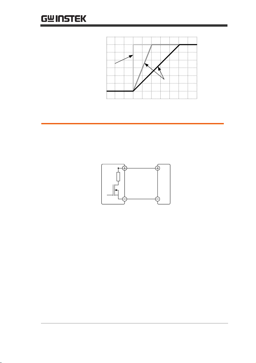
The PPX has selectable slew rates for CC and
CV mode. This gives the PPX power supply the
ability to limit the current/voltage draw of the
power supply. Slew rate settings are divided
into High Speed Priority and Slew Rate
Priority. High speed priority mode will use the
fastest slew rate for the instrument. Slew Rate
Priority mode allows for user adjustable slew
rates for CC or CV mode. The rising and falling
slew rate can be set independently.
Slew Rate
22
GETTING STARTED
High Speed
Priority
mode
Slew rate =
Enabled
Background
The PPX DC power supplies employ a bleed
resistor in parallel with the output terminals.
PPX
Load
Bleed
resistor
Bleed resistors are designed to dissipate the
power from the power supply filter capacitors
when power is turned off and the load is
disconnected. Without a bleed resistor, power
may remain charged on the filter capacitors for
some time and be potentially hazardous.
In addition, bleed resistors also allow for
smoother voltage regulation of the power
supply as the bleed resistor acts as a minimum
voltage load.
The bleed resistance can be turned on or off
using the configuration settings.
Bleeder Control
23

PPX Series User Manual
Note
By default the bleed resistance is on. For battery
charging applications, be sure to turn the bleed
resistance off as the bleed resistor can discharge
the connected battery when the unit is off.
OVP
Over voltage protection (OVP) prevents a high
voltage from damaging the load. This alarm
can be set by the user.
OCP
Over current protection prevents high current
from damaging the load. This alarm can be set
by the user.
UVL
Under voltage limit. This function sets a
minimum voltage setting level for the output.
It can be set by the user.
OTP
Over temperature protection protect the
instrument from overheating
AC ALARM
When AC input voltage or frequency is
abnormal or beyond the AC power range
under operation, the alarm will be generated.
SENSE ALARM
This alarm function is activated when real
output voltage is larger than sense output
voltage.
Alarm output
Alarms are output via the analog control
connector. The alarm output is an isolated
open-collector photo coupler output.
Alarms
The PPX power supplies have a number of protection features.
When one of the protection alarms is set, the ALM icon on the
display will be lit. For details on how to set the protection modes,
please see page 47.
24

GETTING STARTED
Inrush current
When the power supply switch is first turned
on, an inrush current is generated. Ensure there
is enough power available for the power
supply when first turned on, especially if a
number of units are turned on at the same
time.
Caution
Cycling the power on and off quickly can cause the
inrush current limiting circuit to fail as well as
reduce the working life of the input fuse and power
switch.
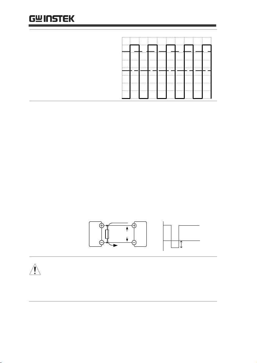
Pulsed or Peaked
loads
When the load has current peaks or is pulsed, it
is possible for the maximum current to exceed
the mean current value. The PPX power supply
ammeter only indicates mean current values,
which means for pulsed current loads, the
actual current can exceed the indicated value.
For pulsed loads, the current limit must be
increased, or a power supply with a greater
capacity must be chosen. As shown below, a
pulsed load may exceed the current limit and
the indicated current on the power supply
ammeter.
Considerations
The following situations should be taken into consideration when
using the power supply.
25
PPX Series User Manual
Current limit
level
Measured
Ammeter
current
Reverse Current:
Regenerative load
When the power supply is connected to a
regenerative load such as a transformer or
inverter, reverse current will feed back to the
power supply. The PPX power supply cannot
absorb reverse current. For loads that create
reverse current, connect a resistor in parallel
(dummy load) to the power supply to bypass
the reverse current. To calculate the resistance
for the dummy resistor, RD, first determine the
maximum reverse current, IR, and determine
what the output voltage, EO, will be.
RD(Ω) ≤ EO(V) ÷ IR(A)
PPX
Load
R
D
I
R
I
R
-
+
E
O
Output
Current
Note
The current output will decrease by the amount of
current absorbed by the resistor.
Ensure the resistor used can withstand the power
capacity of the power supply/load.
26
GETTING STARTED
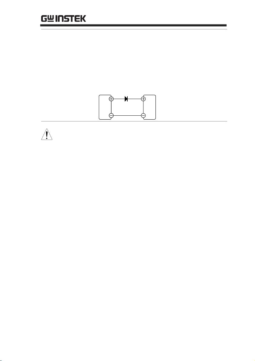
Reverse Current:
Accumulative
energy.
When the power supply is connected to a load
such as a battery, reverse current may flow
back to the power supply. To prevent damage
to the power supply, use a reverse-currentprotection diode in series between the power
supply and load.
PPX
Load
Diode
CAUTION
Ensure the reverse withstand voltage of the diode
is able to withstand 2 times the rated output
voltage of the power supply and the forward
current capacity can withstand 3 to 10 times the
rated output current of the power supply.
Ensure the diode is able to withstand the heat
generated in the following scenarios.
When the diode is used to limit reverse voltage,
remote sensing cannot be used.
27
PPX Series User Manual
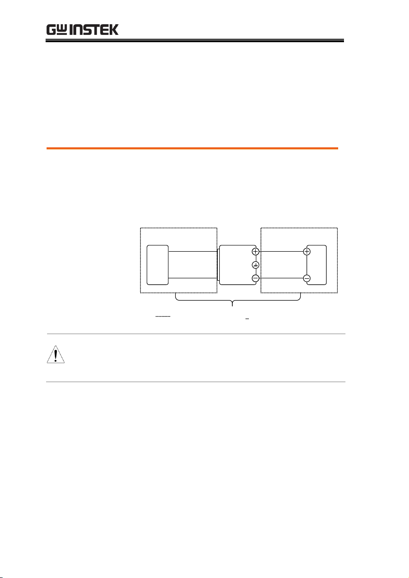
Floating
As the output terminals are floating, the load
and all load cables must have an insulation
capacity that is greater than the isolation
voltage of the power supply.
PPX
Load
Ext-V
Ext-R
Analog
connector
( ) Insulation capacity > isolation voltage
of power supply
WARNING
If the insulation capacity of the load and load
cables are not greater than the isolation voltage of
the power supply, electric shock may occur.
Grounding
The output terminals of the PPX power supplies are isolated with
respect to the protective grounding terminal. The insulation
capacity of the load, the load cables and other connected devices
must be taken into consideration when connected to the protective
ground or when floating.
28

GETTING STARTED
Grounded output
terminal
If the positive or negative terminal is connected
to the protective ground terminal, the
insulation capacity needed for the load and
load cables is greatly reduced. The insulation
capacity only needs to be greater than the
maximum output voltage of the power supply
with respect to ground.
PPX
Load
Ext-V
Ext-R
Analog
connector
( ) Insulation capacity > voltage of power
supply with respect to ground
CAUTION
If using external voltage control, do not ground
the external voltage terminal as this will create a
short circuit.
29

PPX Series User Manual
Set Up...................................................................... 31
Power Up ...........................................................................................31
Wire Gauge Considerations ...........................................................32
Output Terminals .............................................................................33
Connection with the front panel output terminal ..................... 33
Using the Rack Mount Kit .............................................................34
How to Use the Instrument ...........................................................34
Reset to Factory Default Settings ..................................................38
View System Version and Build Date ..........................................39
Menu Tree ................................................................ 40
Menu Page - 1 ...................................................................................41
Menu Page - 2 ...................................................................................42
Menu Page - 3 ...................................................................................43
D-Log .................................................................................................44
PROT .................................................................................................44
TEST ..................................................................................................45
Basic Operation ....................................................... 46
Setting OVP/OCP/UVL Levels ...................................................47
Set to C.V. Priority Mode ...............................................................51
Set to C.C. Priority Mode ...............................................................55
Display Modes ..................................................................................59
Panel Lock .........................................................................................60
Save Setup .........................................................................................61
Recall Setup .......................................................................................62
Remote Sensing ................................................................................64
Temperature ......................................................................................66
Data Logger.......................................................................................71
Sequence Test .......................................................... 74
Sequence Script File Format ..........................................................75
Sequence Script Settings .................................................................75
Sequence Step Edit Settings ...........................................................77
Setting Sequence Script Configurations .......................................82
Run Sequence Script ........................................................................94
Load Sequence Script ......................................................................98
Save Sequence Script .................................................................... 101
OPERATION
30
Set Up
Background
Make sure that the power source is shut off.
Use the AC power cable supplied with the
product.
Steps
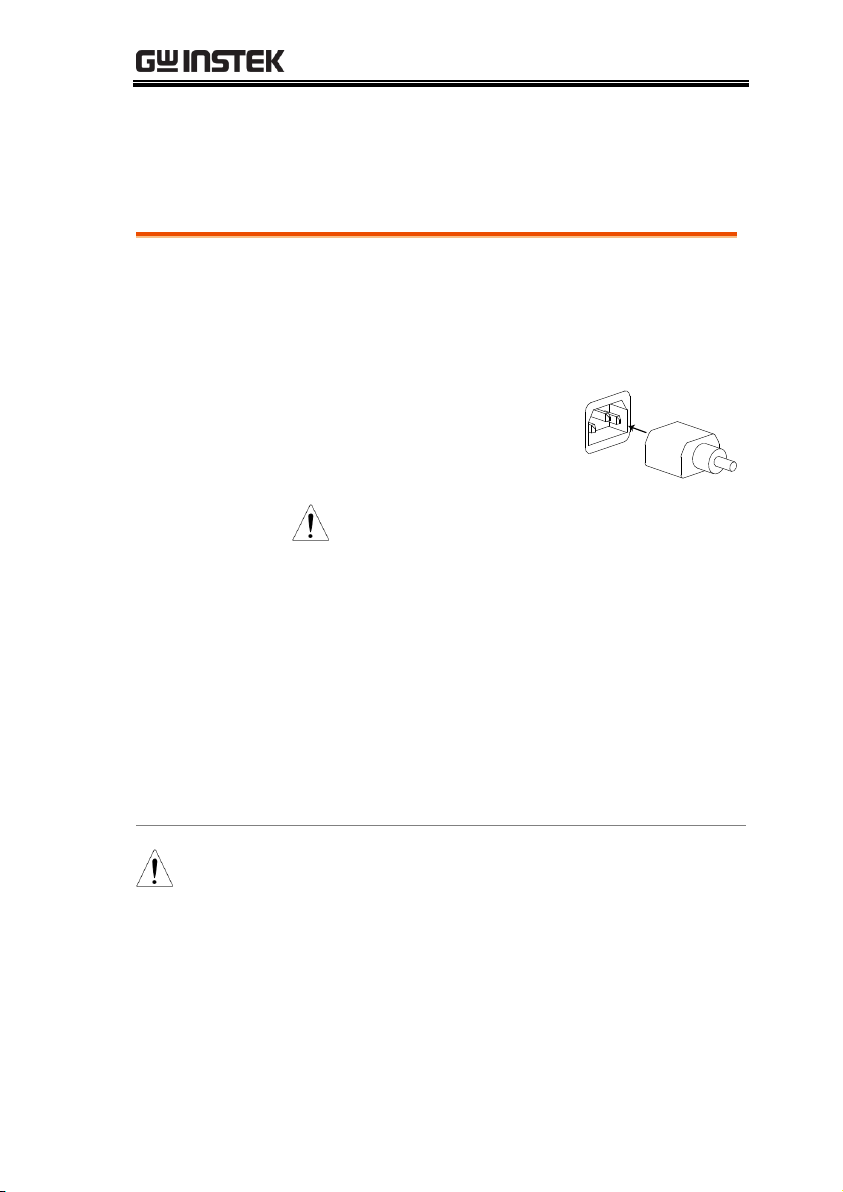
1. Connect the power cord to
the rear panel socket.
Note
Before connecting the power plug to
an AC line outlet, make sure the
voltage selector switches of the bottom
panel in the correct position.
Disconnect power cord and test leads
before replacing fuse. Refer to page 19
for more details.
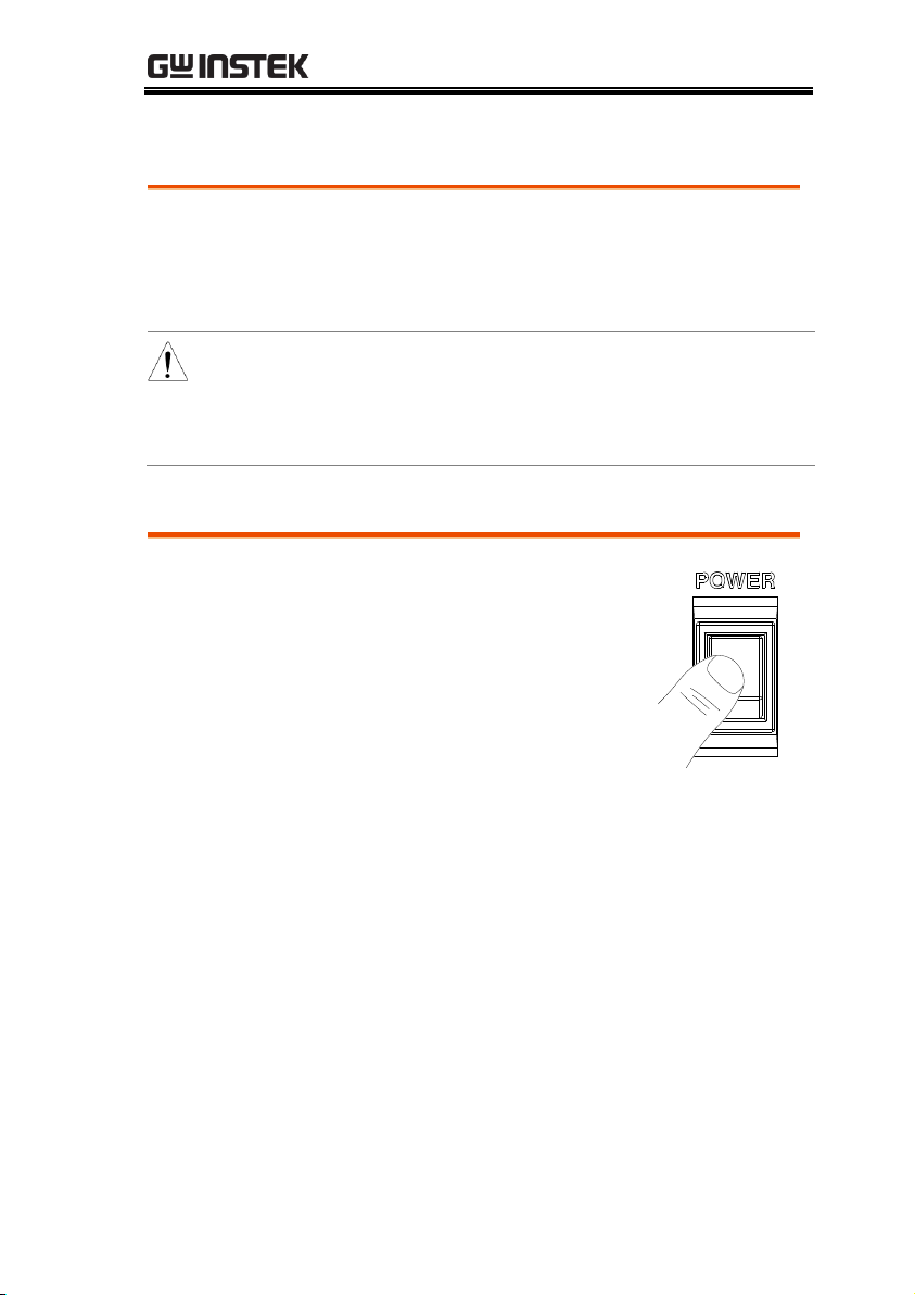
2. Press the POWER switch on. If used for the
first time, the default settings will appear on
the display, otherwise The PPX recovers the
state right before the power was last turned
OFF.
CAUTION
Do not turn the power on and off quickly. Please
wait for the display to fully turn off.
Power Up
OPERATION
31

PPX Series User Manual
Background
Before connecting the output terminals to a
load, the wire gauge of the cables should be
considered. It is essential that the current
capacity of the load cables is adequate. The
rating of the cables must equal or exceed the
maximum current rated output of the
instrument.
Recommended
wire gauge
Wire Gauge
Nominal Cross
Section
Maximum Current
28
0.10
3
26
0.15
4
24
0.25
5
22
0.35
7
20
0.55
9
18
1
12
The maximum temperature rise can only be 60
degrees above the ambient temperature. The
ambient temperature must be less than 30
degrees.
Wire Gauge Considerations
32
OPERATION
Background
Before connecting the output terminals to the
load, first consider whether voltage sense will
be used, the gauge of the cable wiring and the
withstand voltage of the cables and load.
WARNING
Dangerous voltages. Ensure that the power to the
instrument is disabled before handling the power
supply output terminals. Failing to do so may lead
to electric shock.
Steps
1. Turn the power switch off.
2. Connect the test lead includes in the accessory
parts to front panel output terminal.
3. Fix the load cables firmly to eliminate loose
connections from the front output terminals
and load cables.
Output Terminals
Connection with the front panel output terminal
33
PPX Series User Manual
Background
The PPX series has an optional Rack Mount Kit
(GW Instek part number: GRA-441-J [JIS],
GRA-441-E [EIA]) that can be used to hold up
to 4 PPX units into rack.
GRA-441-E [EIA]
Rack mount
diagram
GRA-441-J [JIS]
Rack mount
diagram
Background
The PPX power supplies generally use the
knob key and arrow keys to enter each page
and setting, to return to previous page, to edit
numerical values or to confirm settings.
The following section will explain some of
these concepts in detail.
Using the Rack Mount Kit
How to Use the Instrument
34
OPERATION
Example 1
Use the knob key and arrow keys to set a
voltage of 10.100 volts.
1. From the main display, scroll knob
key to move cursor to V Set field.
2. Click the knob key to enter the V
Set field.
3. Use arrow keys to move the cursor
to desired digits followed scrolling
knob key to edit values. Repeat the
step for each digit until target value.
Cursor
35

PPX Series User Manual
4. Click the knob key to confirm the
input value setting (10.100).
Example 2
Use the knob key to enter Measurement
Average field and setting High option. Also, use
the left arrow key to return to the previous page.
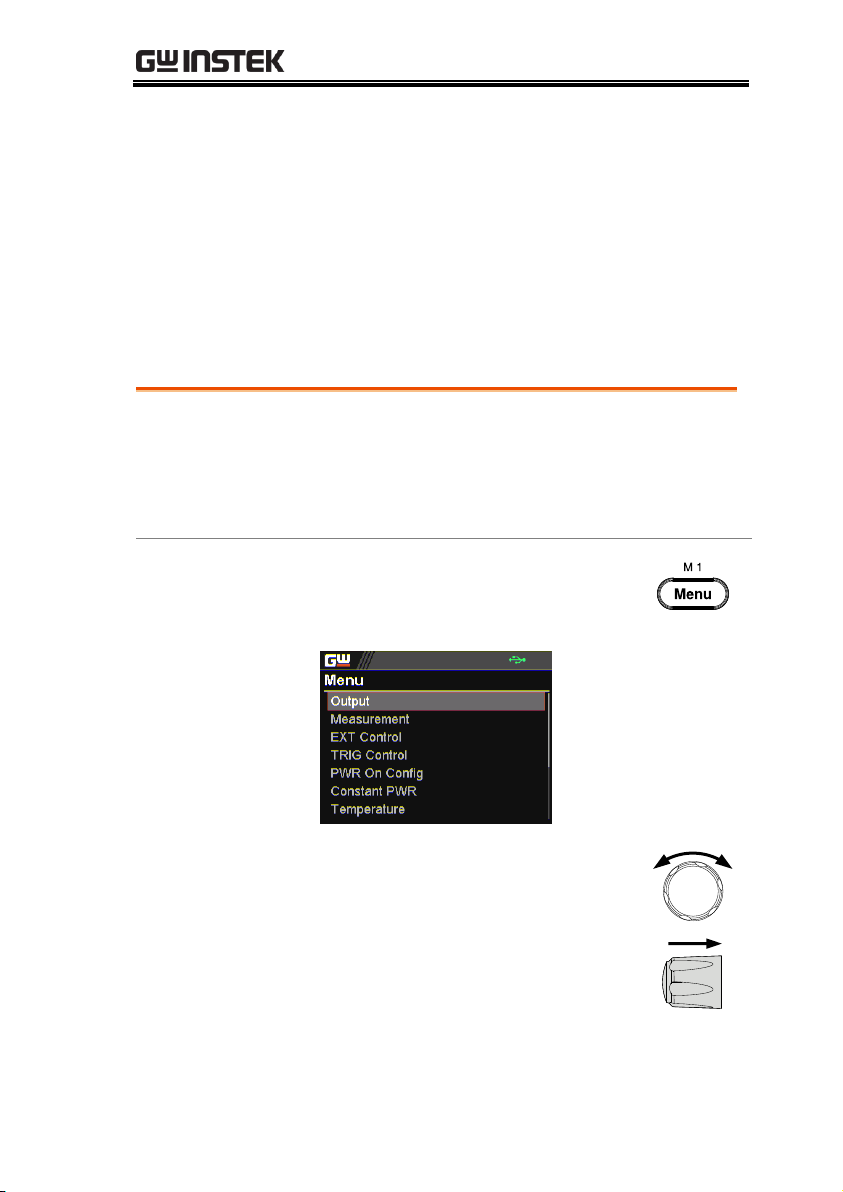
1. Press the Menu key to enter the
Menu page.
2. Scroll the knob key to move to the
Measurement field followed by
clicking the knob key to enter the
Measurement page.
36

OPERATION
3. Click the knob key to enter the
Measurement Average field
followed by scrolling the knob key
to select High option.
4. Click the knob key to confirm the
High option for Measurement
Average.
5. Click the left arrow key to return to
the previous page – Menu page.
37

PPX Series User Manual
Background
The Recall Setup allows the PPX series to be
reset back to the factory default settings. See
page 210 for the default factory settings.
Steps
1. Press the Menu key to enter the
Menu page.
2. Scroll the knob key to move to the
Save/Recall field followed by
clicking the knob key to enter the
Save/Recall page.
3. Scroll knob key to move to the
Recall Mem Set field. Click knob
key to enter the field followed by
scrolling knob key to select
Default option. Click knob key
again to confirm setting.
Reset to Factory Default Settings
38

OPERATION
Background
The System Information allows you to view the
PPX model name, serial number as well as
firmware version.
Steps
1. Press the Menu key to enter the
Menu page.
2. Scroll the knob key to move to the
Utility field followed by clicking the
knob key to enter the Utility page.
3. Click the knob key to enter the
System Information page where
PPX model name, serial number, as
well as firmware version are
displayed.
View System Version
39
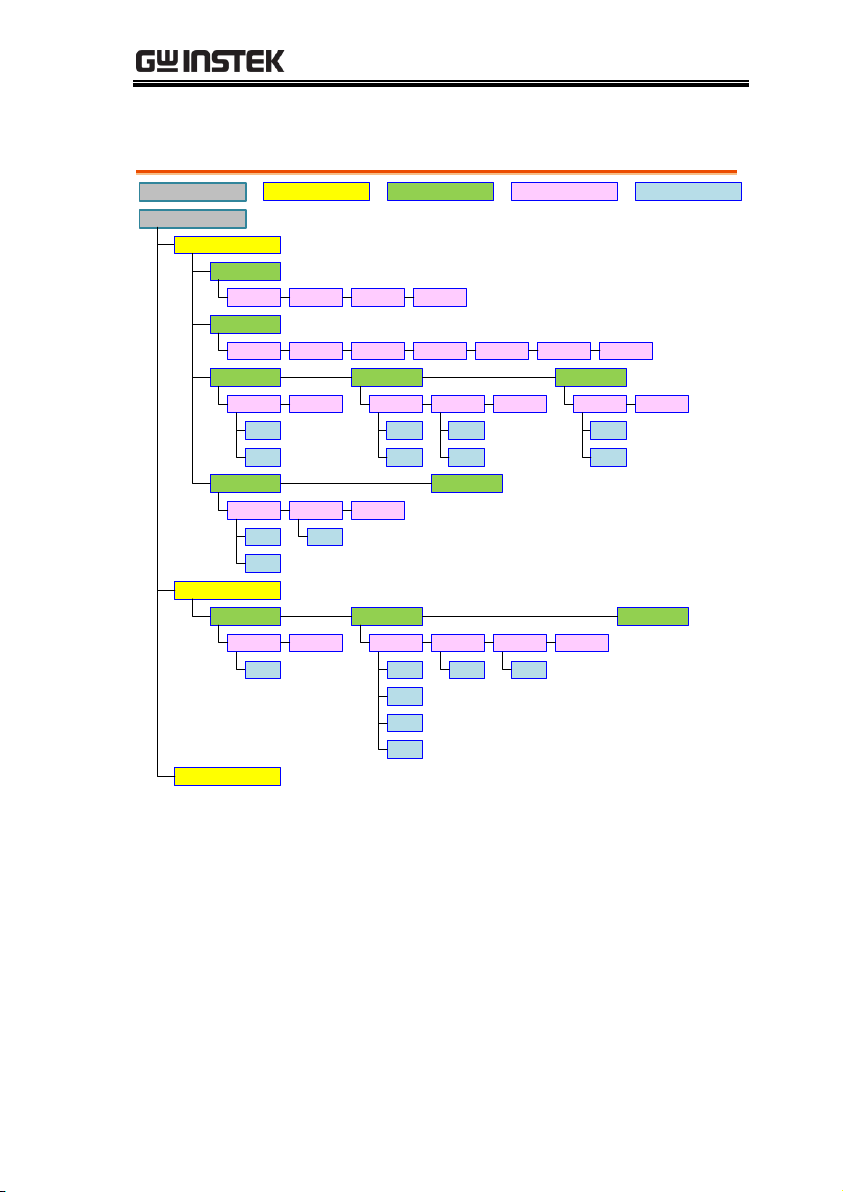
Menu Tree
Convention
Use the menu trees as a handy reference for the power
supply functions and properties. The PPX-1005/PPX2002/PPX-2005/PPX-3601/PPX-3603/PPX-10H01 menu
system is arranged in a hierarchical tree. Each
hierarchical level, which is coated in varied colors, can
be navigated through the orders within the diagrams
below.
For example: To set the measurement average high:
○
1 Press the
Menu
key.
○
2 Navigate to the Measurement option.
○
3 Enter the Measure Average option.
○
4 Select High.
Level 2
Level 1
Level 3
Level 4
Level 5
Menu
Measurement
Measure Average
Voltage Range Current Range
Off
(default)
Low
Middle
High
Auto
(default)
VH
VL
Auto
(default)
IH
IM
IL
ILL
Return
1
2
3
4
PPX Series User Manual
40
Menu Page - 1
Menu
Output
Measurement
Level 2Level 1 Level 3 Level 4
Output On Dly Output Off Dly
Remote Sense V/I Slew Rate
0 sec
(default)
0 sec
(default)
2 Wire
(default)
CVHS
(default)
4 Wire
CCHS
CVLS
CCLS
R_V Slew Rate F_V Slew Rate
0.0001 V/ms
(default by model)
0.0001 V/ms
(default by model)
R_C Slew Rate F_C Slew Rate
0.00001 A/ms
(default by model)
0.00001 A/ms
(default by model)
Measure Average
Voltage Range Current Range
Off
(default)
Low
Middle
High
Auto
(default)
VH
VL
Auto
(default)
IH
IM
IL
ILL
Return
Return
EXT Control
CV Control CC Control Output Type
Front Panel
(default)
External V
External R
Front Panel
(default)
External V
External R
Low
High
(default)
Output Enable Return
Off
(default)
On
TRIG Control
Trigin Level Trigin Action Trigin Voltage
Low
High
(default)
None
(default)
Output
0.000 V
(default)
Trigin Current
Trigin Memory
0.0000 A
(default)
V/I Set
Memory
Trigout Level Trigout Source
M1~M10
(M1 default)
Low
(default)
High
None
(default)
Output
V/I Set
Memory
Trigout Width
1.0 ms
(default)
Return
OPERATION
41

Menu Page - 2
Menu
Power On Config
Level 2Level 1 Level 3 Level 4
Power On Status
Safe
(default)
Return
Force
Auto
Constant PWR
Control
Off
(default)
Power
On
Auto
Return
110.2 W
(default by model)
Temperature
Control
Off
(default)
Unit
On
°C
(default)
°F
Output Safe
Off
(default)
On
Monitor
100.0 °C
(default)
Adjust
0.0 °C
(default)
Return
Save/Recall
Save Mem Set
M1~M10
(M1 default)
Recall Mem Set
M1~Default
(M1 default)
Return
Interface
UART
Level 5
Baud Rate
9600
(default)
Data Bits
7 Bits
8 Bits
(default)
Stop Bits
1
(default)
2
Parity
None
(default)
Odd
Even
Mode
Disable
RS232
(default)
RS485
Address
0~30
(0 default)
Return
LAN
MAC
Address
Hostname Hostname
Off
(default)
On
IP Address
Subnet
Mask
Gateway IP
DNS
Address
Return
Socket
2268
GPIB(Option)
Address
1~30
(8 default)
USB
USB
Disable
Auto
Full
(default)
Web Server
USB
Off
(default)
On
Return Return Return Return
Return
PPX Series User Manual
42
Menu Page - 3
Menu
System
Information
Date & Time
Level 2Level 1 Level 3 Level 4
Year Month Day Hour
Model
Name
Serial
Number
Version Return
Minute Save Return
Keyboard
Lock Mode
Output
Off
Output
On/Off
(default)
Return
Buzzer
Protect
Off
On
(default)
Keyboard
Off
(default)
On
Return
Bleeder
Bleeder
Off
On
(default)
Communication
Monitor
Enable
Off
(default)
On
Return
Timer Return
60 s
(default)
Level 5
Utility
Return
License
Install File Return
APP
XXXX.lis
AH/WH Meter
(Option)
Mode AHour
Disable
(default)
Reset
AHour
Whour
WHour Return
999999999.
999
(default)
999999999.
999
(default)
Return
Calibration
(need password)
OPERATION
43

D-Log
Data Logger
Type
Level 2Level 1 Level 3
None
(default)
Save USB
Send Remote
Sample Period Subfolder
1.0 s
(default)
0000
(default)
Protect
Voltage Limit
Level 2Level 1 Level 3
Off
(default)
On
UVL OVP Level
0.000 V
(default)
22.00 V
(default by model)
Current Limit
Off
(default)
On
OCP Level
5.500 A
(default by model)
OCP Delay
0.050 s
(default)
PROT
PPX Series User Manual
44

TEST
Test
Sequence
Level 2Level 1 Level 3
Run
Total Step
Level 4
Off
On
4
(load file)
Cycle Number
None
Cycle Start
None
Cycle End
None
Sequence Edit
Step
Level 5
1
Point
None
Exit
Log0 Log2
INF
3
(load file)
1
(load file)
4
(load file)
Pause
Start
Log1
Trigin
End
Output
Off
On
(load file)
Time
2.00 s
(load file)
Voltage
10.000 V
(load file)
Current
0.5000 A
(load file)
OVP Level
22.00 V
(load file)
OCP Level
5.500 A
(load file)
Bleeder
Off
On
(load file)
None
V/I
Slew Rate
CCHS
CCLS
None CVHS
CVLS
(load file)
R_V
Slew Rate
0.0100
V/ms
(load file)
F_V
Slew Rate
0.2000
V/ms
(load file)
R_C
Slew Rate
0.05000
A/ms
(load file)
F_C
Slew Rate
0.0500
A/ms
(load file)
Buzzer
Off
On
(load file)
None
Measure
Average
Low
High
None
(load file)
Off
Middle
Jump To
None
(load file)
Jump Count
None
(load file)
Trigger
Out
None
(load file)
Return
Sequence Save
Save From
Edit
(default)
Save To
Internal
t001.csv
(default)
Save To
USB
xxxx.csv
(auto)
Return
Load
t001.csv
(default)
Return
OPERATION
45

PPX Series User Manual
Basic Operation
This section describes the basic operations required to operate the
power supply.
Setting OVP/OCP/UVL → from page 47
C.V. priority mode → from page 51
C.C. priority mode → from page 55
Display mode → page 59
Panel lock → page 60
Save setups → from page 61
Recall setups → from page 62
Remote sensing → from page 64
Temperature → from page 66
Data Logger → from page 71
Before operating the power supply, please see the Getting Started
chapter, page 8.
46

OPERATION
Background
The OVP level and OCP level has a selectable
range that is based on the output voltage and
output current, respectively. The OVP and OCP
level is set to the highest level by default. The
actual selectable OVP and OCP range depends
on the PPX model.
When one of the protection measures are on,
the type of alarm message will be shown on
display. Press Shift + PROT key to clear any
protection alarm messages that have been
tripped. By default, the output will turn off
when the OVP or OCP protection levels are
tripped.
The UVL will prevent you from setting a
voltage that is less than the UVL setting. The
UVL setting range is from 0% ~ 105% of the
rated output voltage.
Before setting the protection settings:
• Ensure the load is not connected.
• Ensure the output is turned off.
Note
You can enter the PROT setting to apply limits to
the voltage and current settings, respectively. You
can set limitations so that the values do not exceed
the set OVP and the set OCP level, and so that the
values are not lower than the set UVL trip point. By
using this feature, you can avoid turning the output
off by mistakenly setting the voltage or current to a
value that exceeds the set OVP or OCP level or to a
value that is lower than the set UVL trip point.
If you have selected to limit the voltage setting, you
Setting OVP/OCP/UVL Levels
47
PPX Series User Manual
will no longer be able to set the output voltage to a
value that is above about 95% of the OVP trip point
or to a value that is lower than the UVL trip point. If
you have selected to limit the current setting, you
will no longer be able to set the output current to a
value that is above about 95% of the OCP trip point.
Lastly, the Delay time setting for OCP delays trigger
for OCP by set time period.
Steps
1. Press the PROT key to enter the
Protect page.
Enable/Disable
Voltage and
Current Limit
2. Scroll the knob key to move
between Voltage/Current Limit
fields. Click the knob key to enter
each field, respectively. Scroll the
knob key to turn ON/OFF the
function. Further click the knob
key again to confirm your setting.
Option
On, Off
Setting the
Protection Level
3. Scroll the knob key to move among
UVL/OVP/OCP Level fields. Click
the knob key to enter each field,
respectively. Scroll the knob key to
adjust value, along with the arrow
keys to change among digits
followed by clicking the knob key
to confirm set value.
48

OPERATION
Setting Range
Model
OCP
OVP
UVL
PPX-1005
0.25~5.5
0.5~11
0~10.5
PPX-2002
0.1~2.2
1~22
0~21.0
PPX-2005
0.25~5.5
1~22
0~21.0
PPX-3601
0.05~1.1
1.8~39.6
0~37.8
PPX-3603
0.15~3.3
1.8~39.6
0~37.8
PPX-10H01
0.05~1.1
5~110
0~105
Note
The UVL setting range is from 0% ~ 105% of the rated
output voltage. It depends on Voltage Limit On/Off to
activate/deactivate UVL setting.
The OVP setting range is from 5% ~ 110% of the rated
output voltage.
The OCP setting range is from 5% ~ 110% of the rated
output current.
Setting the
Delay Time
4. Scroll the knob key to move
between OCP Delay fields. Click
the knob key to enter each field,
respectively. Scroll the knob key to
adjust value, along with the arrow
keys to change among digits
followed by clicking the knob key
to confirm set value.
Setting Range
OCP Delay
0.05~2.500 s
49
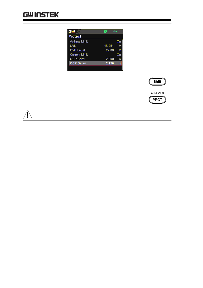
PPX Series User Manual
Clear OVP/OCP
protection
The OVP and OCP protection can
be cleared after it has been tripped
by clicking Shift key + ALM CLR
key.
+
Note
The UVL protection On/Off depends on Voltage Limit.
50

OPERATION
Background
Before setting the power supply to C.V. mode,
ensure:
The output is off.
The load is connected.
Steps
1. Press the Menu key followed by
clicking on Output to enter the
Output page.
2. Scroll the knob key to move to the
V/I Slew Rate field followed by
clicking the knob key to enter the
field.
Set to C.V. Priority Mode
When setting the power supply to constant voltage mode, a current
limit must also be set to determine the crossover point. When the
current exceeds the crossover point, the mode switches to C.C.
mode. For details about C.V. operation, see page 21.
C.C. and C.V. mode have two selectable slew rates: High Speed
Priority and Slew Rate Priority. High Speed Priority will use the
fastest slew rate for the instrument while Slew Rate Priority will
use a user-configured slew rate.
51
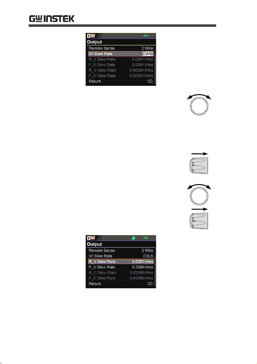
PPX Series User Manual
3. Scroll the knob key to select
between CVHS (CV High Speed
Priority) and CVLS (CV Slew Rate
Priority) options.
Options
CVHS = CV High Speed Priority
CVLS = CV Slew Rate Priority
4. Press the knob key to save the
selected option.
5. When CV Slew Rate Priority was
chosen as the operating mode,
scroll knob key to R_V Slew Rate
and F_V Slew Rate fields followed
by clicking knob key to enter the
fields, respectively.
52

OPERATION
6. Scroll the knob key to adjust value,
along with the arrow keys to
change among digits followed by
clicking the knob key to confirm set
value, respectively.
R_V Slew Rate / F_V Slew Rate Setting Range
Model
Max. Value
Min. Value
PPX-1005
0.0001V/ms
0.1V/ms
PPX-2002
0.0001V/ms
0.2V/ms
PPX-2005
0.0001V/ms
0.2V/ms
PPX-3601
0.0001V/ms
0.36V/ms
PPX-3603
0.0001V/ms
0.36V/ms
PPX-10H01
0.001V/ms
0.5V/ms
7. Press the Menu key again to return
to the main screen.
8. Scroll the knob key to move to V
Set. Click knob key followed by
scrolling knob key, along with the
arrow keys to change among digits,
to set the voltage. Click knob key
to confirm the set value.
53

PPX Series User Manual
9. Scroll the knob key to move to I
(A) Set. Click knob key followed
by scrolling knob key, along with
the arrow keys to change among
digits, to set the current limit
(crossover point). Click knob key
to confirm the set value.
10. Press the Output key. The Output
key becomes illuminated.
CV icon
appears
VSR (CV
Slew Rate
Priority)
54
OPERATION
Background
Before setting the power supply to C.C. mode,
ensure:
The output is off.
The load is connected.
Steps
1. Press the Menu key followed by
clicking on Output to enter the
Output page.
2. Scroll the knob key to move to the
V/I Slew Rate field followed by
clicking the knob key to enter the
field.
Set to C.C. Priority Mode
When setting the power supply to constant current mode, a voltage
limit must also be set to determine the crossover point. When the
voltage exceeds the crossover point, the mode switches to C.V.
mode. For details about C.C. operation, see page 21.
C.C. and C.V. mode have two selectable slew rates: High Speed
Priority and Slew Rate Priority. High Speed Priority will use the
fastest slew rate for the instrument while Slew Rate Priority will
use a user-configured slew rate.
55

PPX Series User Manual
3. Scroll the knob key to select
between CCHS (CC High Speed
Priority) and CCLS (CC Slew Rate
Priority) options.
Options
CCHS = CC High Speed Priority
CCLS = CC Slew Rate Priority
4. Press the knob key to save the
selected option.
5. When CC Slew Rate Priority was
chosen as the operating mode,
scroll knob key to R_C Slew Rate
and F_C Slew Rate fields followed
by clicking knob key to enter the
fields, respectively.
56

OPERATION
6. Scroll the knob key to adjust value,
along with the arrow keys to
change among digits followed by
clicking the knob key to confirm set
value, respectively.
R_C Slew Rate / F_C Slew Rate Setting Range
Model
Max. Value
Min. Value
PPX-1005
0.00001A/ms
0.05A/ms
PPX-2002
0.00001A/ms
0.02A/ms
PPX-2005
0.00001A/ms
0.05A/ms
PPX-3601
0.00001A/ms
0.01A/ms
PPX-3603
0.00001A/ms
0.03A/ms
PPX-10H01
0.00001A/ms
0.005A/ms
7. Press the Menu key again to return
to the main screen.
8. Scroll the knob key to move to V
Set. Click knob key followed by
scrolling knob key, along with the
arrow keys to change among digits,
to set the voltage limit (crossover
point). Click knob key to confirm
the set value.
57

PPX Series User Manual
9. Scroll the knob key to move to I
(A) Set. Click knob key followed
by scrolling knob key, along with
the arrow keys to change among
digits, to set the current. Click
knob key to confirm the set value.
10. Press the Output key. The Output
key becomes illuminated.
CC icon
appears
ISR (CC
Slew Rate
Priority)
58
OPERATION
Steps
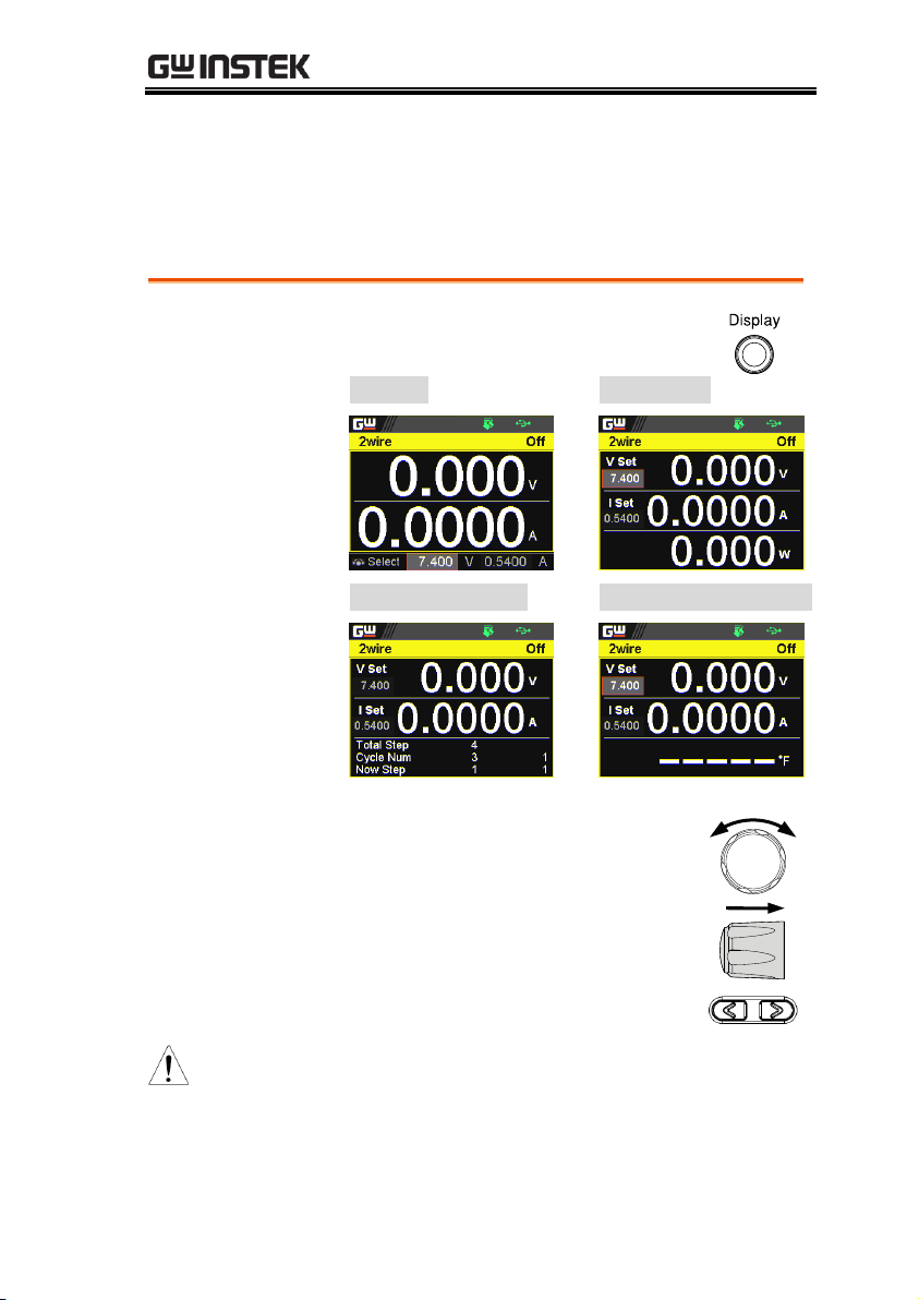
1. Press the Display key on main
screen to toggle among each mode.
V and A
V, A and W
V, A and Sequence
V, A and Temperature
2. Scroll the knob key to change
between V and I (A) Set fields.
Click the Knob key followed by
scrolling it to adjust value, along
with the arrow keys to change
among digits followed by click
knob key again to confirm value.
Note
When sequence mode is selected, V and I set can
Not be modified here.
Refer to page 95 for details of V, A and Sequence
display and page 69 for details of V, A and
Temperature.
Display Modes
The PPX series power supplies allow you to view the output in 4
different modes: General (V/A), Power (V/A/W), Sequence
(V/A/Sequence) or Temperature (V/A/T).
59

PPX Series User Manual
Activate the
panel lock
Press the Lock (Unlock/Local) key
to activate the panel lock. The lock
icon will be shown on display.
Panel
Lock icon
Disable the
panel lock
Press the Shift key followed by the
Lock (Unlock/Local) key to disable
the panel lock. The lock icon will
thus be cleared from display.
+
Note
By default, the output key is disabled when lock
function is activated. However, if Output On/Off
function is selected under Utility section, the
output key can be tuned On/Off even though the
lock mode is activated. Refer to page 146 for detail.
Panel Lock
The panel lock feature prevents settings from being changed
accidentally. When activated, all keys including the knob key
except the Shift key, Lock (Unlock/Local) key and Output key (if
active) will be disabled.
If the instrument is remotely controlled via the USB/LAN/GPIB
interface, the panel lock is automatically enabled.
60

OPERATION
Steps
1. Press the Menu key to enter the
Menu page.
2. Scroll the knob key to move to the
Save/Recall field followed by
clicking the knob key to enter the
Save/Recall page.
3. Click knob key to enter the Save
Mem Set field followed by
scrolling knob key to select one of
the options for saving setting. Click
knob key again to confirm the
saving.
Options
M1 ~ M10
Save Setup
The PPX has up to 10 memory storage (M1 ~ M10) to save the set
current, set voltage, OVP, OCP and ULV settings.
61

PPX Series User Manual
Recall Memory
from Save/Recall
1. Press the Menu key to enter the
Menu page.
2. Scroll the knob key to move to the
Save/Recall field followed by
clicking the knob key to enter the
Save/Recall page.
3. Scroll knob key to move to the
Recall Mem Set field. Click knob
key to enter the field followed by
scrolling knob key to select one of
the options to recall setting. Click
knob key again to confirm.
Options
M1 ~ M10, Default
Recall Setup
The PPX has up to 10 memory storage (M1 ~ M10) to recall the set
current, set voltage, OVP, OCP and ULV settings.
Also, it has 3 dedicated keys (M1, M2, M3) on front panel to
promptly recall the setups.
62

OPERATION
Note
When default is selected, the unit will restore
back to the factory default setting.
Recall Memory
from front panel
keys
1. Press the Shift key followed by M1
~ M3 key on front panel to
promptly recall the set setting.
+
2. The M1 ~ M3 memory setting is
thus recalled quickly with ease.
63

PPX Series User Manual
WARNING
Ensure the output is off before handling the
remote sense connector.
Use sense cables with a voltage rating exceeding
the isolation voltage of the power supply.
Never connect sensing cables when the output is
on. Electric shock or damage to the power supply
could result.
Output terminal
Connector
Overview
When using the remote sensing, make sure the
wires that are used follow the following guidelines:
Wire gauge:
AWG 20 to AWG 14
Strip length:
6.5mm // 0.26 in.
+S: +Sense terminal
-S: -Sense terminal
Note
Be sure to remove the Sense joining cables so the
units are not using local sensing.
Remote Sensing
Remote sense is used to compensate for the voltage drop seen
across load cables due to the resistance inherent in the load cables.
The remote sense terminals are connected to the load terminals to
determine the voltage drop across the load cables.
Remote sense can compensate up to 1 volt for PPX1005/2002/2005/3601/3603 and 3 volts for PPX-10H01
(compensation voltage). Load cables should be chosen with a
voltage drop less than the compensation voltage.
64

OPERATION
Single Load
1. Connect the +S terminal to the positive
potential of the load. Connect the -S terminal to
the negative potential of the load.
Output
+S
-S
PPX
Output
Load
Input
Input
2. Operate the instrument as normal. See the Basic
Operation chapter for details.
Wire Shielding
and Load line
impedance
To help to minimize the oscillation due to the
inductance and capacitance of the load cables,
use an electrolytic capacitor in parallel with the
load terminals.
To minimize the effect of load line impedance
use twisted wire pairing.
PPX
Load
s
s
Twisted pair
Capacitor
Shield the sense wires and connect
the shield to the chassis ground.
Twisted pair
65
PPX Series User Manual
The optional
GTL-205A
Temperature probe adaptor
with thermocouple K type
with 1000mm in length.
Steps
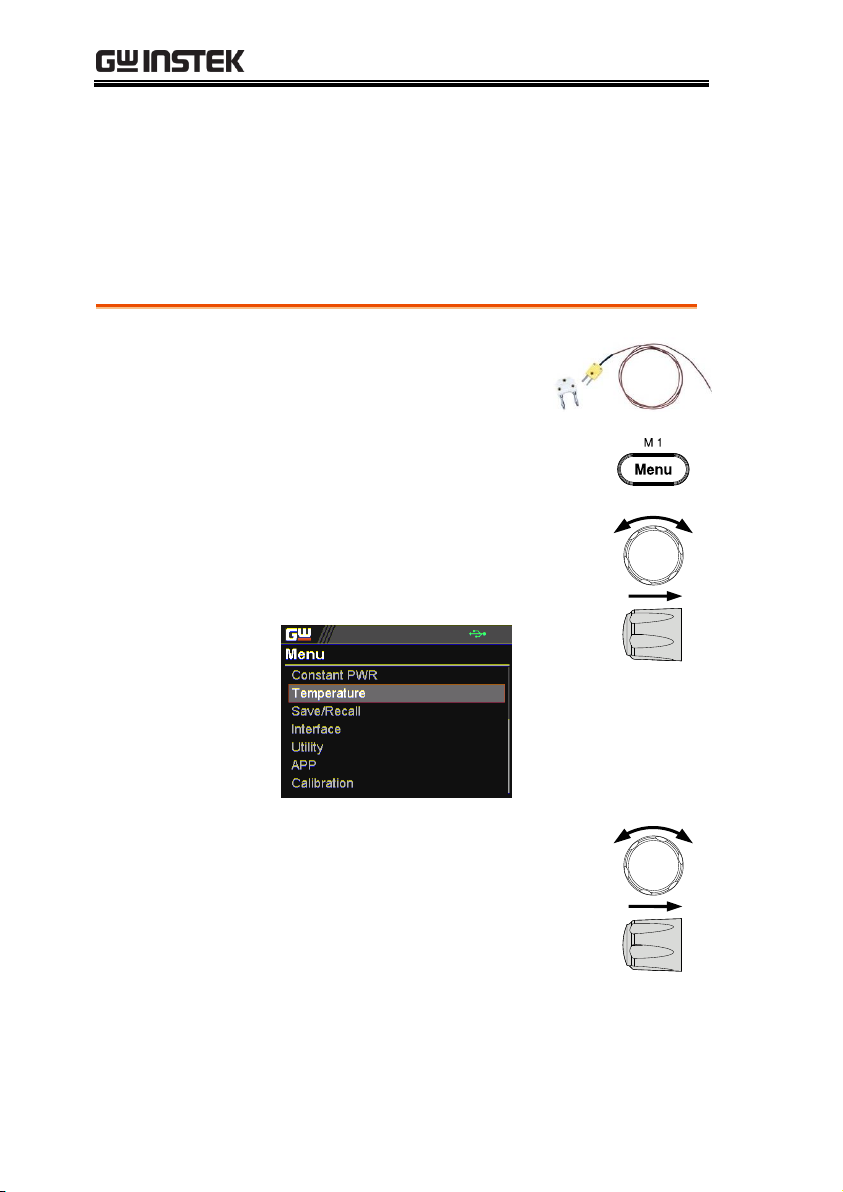
1. Press the Menu key to enter the
Menu page.
2. Scroll the knob key to move to the
Temperature field followed by
clicking the knob key to enter the
Temperature page.
3. Scroll knob key to move to the Unit
field. Click knob key to enter the
field followed by scrolling knob
key to select one of the options for
temperature unit display. Click
knob key again to confirm.
Options
°C, °F
Temperature
The PPX series can measure DUT temperature while power output
simultaneously. Prior to temperature measurement, utilize the
optional accessory GTL-205A, which includes a temperature probe
adaptor with thermocouple K type, to connect between DUT and
TC input on the front panel of PPX series.
66
OPERATION
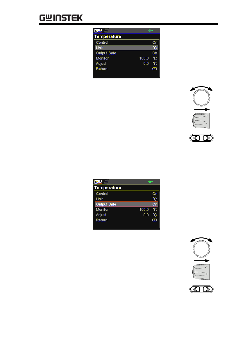
4. Scroll knob key to move to the
Output Safe field, which is used to
monitor temperature of DUT with
user-defined threshold. The power
output stops once threshold is met.
Click knob key to enter the field
followed by scrolling knob key to
turn On/Off the function, along
with the arrow keys to change
among digits. Click knob key again
to confirm.
Options
On, Off
5. Scroll knob key to move to the
Monitor field, which sets
temperature threshold that goes
with Output Safe function. Click
knob key to enter the field
followed by scrolling knob key to
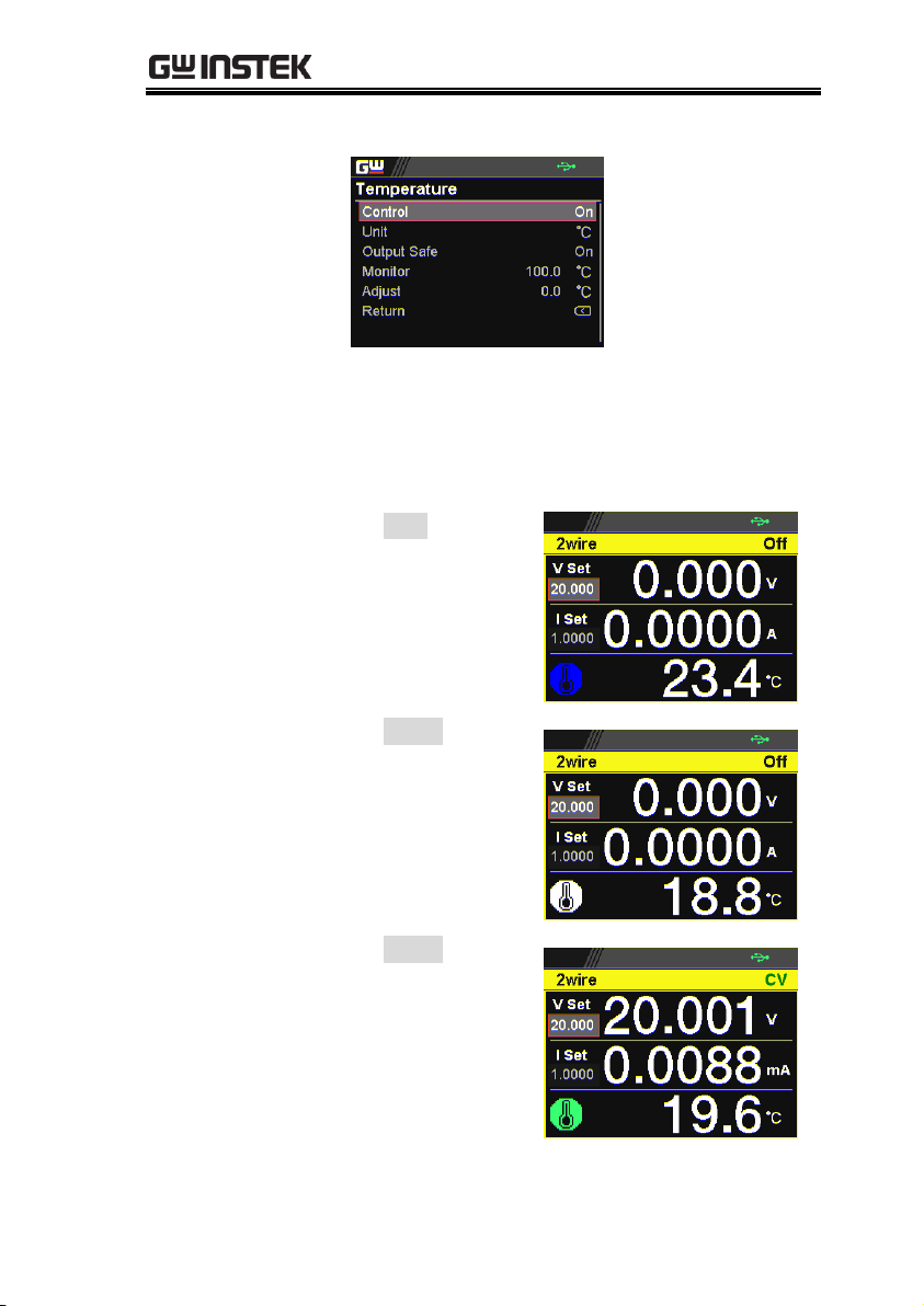
set temperature value, along with
the arrow keys to change among
digits. Click knob key again to
confirm.
67

PPX Series User Manual
Options
°C
-200.0 ~ 1372.0
°F
-328.0 ~ 2501.6
6. Scroll knob key to move to the
Adjust field, which acts like an
user-defined offset value in
accordance with environment
factors by user preference. Click
knob key to enter the field followed
by scrolling knob key to set adjust
value, along with the arrow keys to
change among digits. Click knob
key again to confirm.
Options
°C
-2.5 ~ 2.5
°F
-4.5 ~ 4.5
7. Scroll knob key to move to the
Control field. Click knob key to
enter the field followed by scrolling
knob key to turn On/Off the
temperature measurement function.
Click knob key to confirm.
68
OPERATION
Options
On, Off
Temperature
measurement
status
When it is under V, A and Temperature display
mode, a thermometer icon appears in the
lower-left corner and varied colors of the icon
represent different statuses as follows.
Blue
Temperature
Control On
with no GTL205A
connected
White
Temperature
Control On
with GTL205A
connected
Green
Output Safe
is activated
and Output is
On with GTL205A
connected
69

PPX Series User Manual
Red
The alarm of
short circuit
occurs from
temperature
measurement
70
OPERATION
Steps
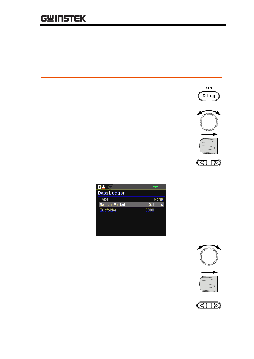
1. Press the D-Log key to enter the
Data Logger page.
2. Scroll the knob key to move to the
Sample Period field, which
determines the interval of data log
saving. Click knob key followed by
scrolling it to adjust value, along
with the arrow keys to change
among digits. Click knob key again
to confirm set period.
Range
0.1s ~ 999.9s
3. Scroll the knob key to move to the
Subfolder field, which creates a
user-defined serial number for
folder in which up to 1000.csv files
are stored. Click knob key
followed by scrolling it to adjust
serial number, along with the
arrow keys to change among
digits. Click knob key again to
confirm setting.
Data Logger
The PPX series can save measured voltage, current and
temperature data into either USB flash disk or send the data to
program via remote control.
71

PPX Series User Manual
Range
0000 ~ 9999
4. Scroll the knob key to move to the
Type field. Click knob key
followed by scrolling it to select a
type for data log saving. Click
knob key to confirm setting.
Type
None
No action will be executed.
Save USB
Save data log into USB disk. It is
required to insert USB disk first.
Send
Remote
Send data log to remote side via
remote control in real time.
Dlog icon in
main display
When Data Logger is activated, the Dlog icon
will be shown on the main screen.
72

OPERATION
Dlog icon
appears
Note
When the Save USB is selected, make sure that
return to Data Logger page to select None for Type
so that the latest data file can be saved properly.
Owing to the fact that data log is being transmitted
in real time via remote control, when the Send
Remote is selected, there is no need to return to
Data Logger page to select None for Type.
73

PPX Series User Manual
Sequence Test
This section describes how to use the Sequence function to edit, run,
load and save sequence scripts for automated testing. The sequence
function is useful if you want to perform a number of tests
automatically. The PPX sequence function can store up to 10 test
scripts in internal memory and also into the connected USB disk.
Each test script can also be programmed in a scripting language.
For more information on how to create sequence scripts via
programs, please contact GW Instek.
Sequence Script File Format → from page 75
Sequence Script Settings → from page 75
Sequence Step Edit Settings → from page 77
Setting Sequence Script Configurations → from page 82
Run Sequence Script → from page 94
Load Sequence Script → from page 98
Save Sequence Script → from page 101
74

OPERATION
Background
The sequence script files are saved in the *.csv
file format. When saving script file into internal
memory, each file is saved as tXXX.csv where
XXX is the file number from 001 to 010. When
saving script file into the USB disk, each file is
saved as S202_XXXX.csv where XXXX is the file
serial number from 0001 to 9999.
Background
This section mainly introduces the settings
within the Sequence page.
Run
It runs sequence script automatically. A script
can be saved in or loaded from the internal
memory or USB disk. Once the Run field is
turned On, return to the main display followed
by pressing Output key to initiate the set
sequence script.
Run
On, Off
Total Step
It determines the total steps for a sequence script.
Each step can be edited from the Edit field.
Total Step
1 ~ 20000
Cycle Number
It sets how many cycles will be repeated. For
example, when a script consists of 6 steps and
cycle number is set 3, the sequence runs the script,
which contains step 1 ~ 6, for 3 times in a row.
Cycle Number
None
No cycle will be repeated.
Sequence Script File Format
Sequence Script Settings
75

PPX Series User Manual
INF
It indicates infinite cycles.
1 ~ 1000000000
It sets cycle(s) from 1 to
1000000000 times.
Cycle Start
It sets which step is the starting step of cycle.
The available steps options vary per total steps.
Cycle Start
None
None of steps is for cycle
start. It fits when no cycle
will be executed.
1 ~ 20000
It sets which step is the
starting point of cycle.
Cycle End
It sets which step is the end step of cycle. The
available steps options vary per total steps.
Cycle End
None
None of steps is for cycle
end. It fits when no cycle
will be executed.
1 ~ 20000
It sets which step is the end
point of cycle.
Note
Jump and Cycle functions can Not be activated at
the same time. Refer to page 81 for details of Jump.
Save
It saves a select sequence script into either
internal memory or the connected USB disk.
Save From
Edit
To select currently edited
script as a source of script
to be saved.
S202_XXXX.csv
If connected USB disk
contains saved scripts, the
files are available to select.
76

OPERATION
Save To Internal
tXXX.csv
To save the selected source
script into a select internal
memory from no. 001 to 010.
Save To USB
S202_XXXX.csv
To save the selected source
script into the USB disk
from no. 0001 to 9999.
Load
It loads a select sequence script from either
connected USB disk or internal memory. Note
that when USB disk is plugged in, memory from
USB disk will prioritize over internal memory.
S202_XXXX.csv
/ tXXX.csv
To load script from USB
disk (S202_XXXX.csv) or
internal memory (tXXX.csv).
Note
When there is any issue occurred from settings,
PPX series will not be able to run sequence script.
The error code along with warning message will be
shown within the prompt message box when Run
filed is enabled.
Background
This section mainly introduces the settings
within the Sequence Edit page, which is used to
edit several parameters for each step.
Step
To select which step to be edited. The available
option(s) depends on the total step setting.
Step
1 ~ 20000
Sequence Step Edit Settings
77

PPX Series User Manual
Point
It sets a core action for select step. The available
options are described as follows.
Point
Start
It sets which step is the starting step
of an entire sequence script. Be aware
that this Start step can only be set
equal to or earlier than the “Cycle
Start”. For example, to set step 3 as
Start and step 2 as Cycle Start is not
available for PPX series.
End
It sets which step is the end step of an
entire sequence script. Be aware that
this End step can only be set equal to
or later than the “Cycle End”. For
example, to set step 2 as End and step
3 as Cycle End is not available for
PPX series.
Exit
It sets which step is the exit step of an
entire sequence script. Generally, a
sequence script can be executed again
after finishing by pressing Output
key. However, when Exit step is set,
the sequence function won’t be
executed again after finishing by
Output key directly.
Pause
It sets which step will be paused
during a sequence script. When a
sequence is paused, press Test key to
continue running the sequence.
Trigin
It sets which step will be executed by
trig-in signal. The Trigin step will be
held until trig-in signal is received by
PPX series unit.
78

OPERATION
Log0
It sets which step will be executed in
stop action for the data log function.
This relates to the Log1 and Log2
actions as the following sections.
Log1
It sets which step will be executed in
the action of saving data log into USB
disk. Once a sequence script runs to
this step, data log will be kept saving
into USB disk instantly until next
Log0 action is met. Refer to page 71
for details.
Log2
It sets which step will be executed in
the action of sending data log to
remote control side. Once a sequence
script runs to this step, data log will
be kept sending to remote control
side until next Log0 action is met.
Refer to page 71 for details.
Output
It sets if power output will be activated for the
select step.
Output
ON, OFF
Time
It sets time duration of execution for the select
step.
Time
0.05 ~ 999.99s
Voltage
It sets output voltage of CV mode for the select
step.
Voltage
0V ~ 105% rated voltage
Current
It sets output limit current of CC mode for the
select step.
Current
0A ~ 105% rated current
79

PPX Series User Manual
OVP Level
It sets over voltage protection setting for the
select step.
OVP Level
5% ~ 110% rated voltage
OCP Level
It sets over current protection setting for the
select step.
OCP Level
5% ~ 110% rated current
Bleeder
It enables or disables discharge loop control for
the select step.
Bleeder
None, ON, OFF
V/I Slew Rate
It sets High Speed Priority and Slew Rate
Priority of CV and CC modes for the select step.
V/I Slew Rate
CVHS
It utilizes the fastest slew rate of CV
mode. Refer to page 51 for more
details.
CCHS
It utilizes the fastest slew rate of CC
mode. Refer to page 55 for more
details.
CVLS
It utilizes the user-configured slew
rate of CV mode. When this option is
selected, go to configure the R_V slew
Rate (rising) and F_V slew rate
(falling) settings, respectively. Refer
to page 51 for more details.
CCLS
It utilizes the user-configured slew
rate of CC mode. When this option is
selected, go to configure the R_C slew
Rate (rising) and F_C slew rate
(falling) settings, respectively. Refer
to page 55 for more details.
80

OPERATION
Buzzer
It enables or disables buzzer sound for the
select step.
Buzzer
ON, OFF
Measure
Average
It sets the speed level of display sampling for
the measure average setting for the select step.
More the average numbers (High), slower the
display update. Refer to page 112 for details.
Measure
Average
Off, Low, Middle, High
Jump To
It sets the target step to jump to. For example,
when step 5 is set for Jump To under the step 2
Edit page, it means that when sequence runs to
step 2, it will directly jump to step 5 at the end
of step 2. The available step option(s) depends
on the total step setting.
Jump To
1 ~ 20000
Jump Count
It sets the number of times to loop the Jump To
step action.
Jump Count
1 ~ 10000
Note
Jump and Cycle functions can Not be activated at
the same time. Refer to page 75 for details of Cycle.
Trigger Out
It sets if trigger out signal will be transmitted
when the sequence runs to the step.
Trigger Out
ON, OFF
Note
When there is any issue occurred from settings,
PPX series will not be able to run sequence script.
The error code along with warning message will be
shown within the prompt message box when Run
filed is enabled.
81

PPX Series User Manual
Steps
1. Press Test key followed by clicking
on Sequence field via knob key to
enter the Sequence page.
2. Scroll knob key to move to the
Total Step field followed by
clicking knob key to enter the field.
Scroll knob key to adjust value
along with arrow keys to change
among digits followed by clicking
knob key to confirm total steps.
Total Step
1 ~ 20000
Setting Sequence Script Configurations
82
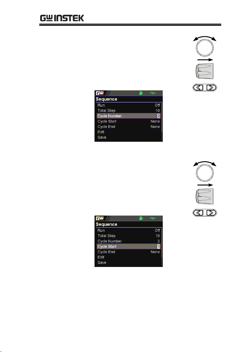
OPERATION
3. Scroll knob key to move to the
Cycle Number field followed by
clicking knob key to enter the field.
Scroll knob key to adjust value
along with arrow keys to change
among digits followed by clicking
knob key to confirm cycle number.
Cycle Number
INF, 1 ~ 1000000000
4. Scroll knob key to move to the
Cycle Start field followed by
clicking knob key to enter the field.
Scroll knob key to adjust value
along with arrow keys to change
among digits followed by clicking
knob key to confirm cycle start.
Cycle Start
1 ~ 20000
83
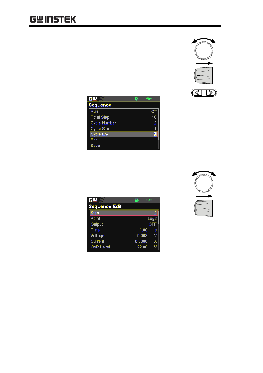
PPX Series User Manual
5. Scroll knob key to move to the
Cycle End field followed by
clicking knob key to enter the field.
Scroll knob key to adjust value
along with arrow keys to change
among digits followed by clicking
knob key to confirm cycle end.
Cycle End
1 ~ 20000
6. Scroll knob key to move to the Edit
field followed by clicking knob key
to enter the Sequence Edit page.
84

OPERATION
7. Scroll knob key to move to the Step
field followed by clicking knob key
to enter the field. Scroll knob key
to select a step along with arrow
keys to change among digits
followed by clicking knob key to
confirm the step to edit.
Step
1 ~ 20000
8. Scroll knob key to move to the Point
field followed by clicking knob key
to enter the field. Scroll knob key to
select an action followed by clicking
knob key to confirm the action for
the step to edit.
Point
Start, End, Exit, Pause, Trigin,
Log0, Log1, Log2
85

PPX Series User Manual
9. Scroll knob key to move to the
Output field followed by clicking
knob key to enter the field. Scroll
knob key to turn on/off output
followed by clicking knob key to
confirm output action.
Output
ON, OFF
10. Scroll knob key to move to the
Time field followed by clicking
knob key to enter the field. Scroll
knob key to adjust value along
with arrow keys to change among
digits followed by clicking knob
key to confirm time setting.
Time
0.05 ~ 999.99s
86

OPERATION
11. Scroll knob key to move to the
Voltage field followed by clicking
knob key to enter the field. Scroll
knob key to adjust value along
with arrow keys to change among
digits followed by clicking knob
key to confirm voltage setting.
Voltage
0V ~ 105% rated voltage
12. Scroll knob key to move to the
Current field followed by clicking
knob key to enter the field. Scroll
knob key to adjust value along
with arrow keys to change among
digits followed by clicking knob
key to confirm current setting.
Current
0A ~ 105% rated current
87

PPX Series User Manual
13. Scroll knob key to move to the
OVP Level field followed by
clicking knob key to enter the field.
Scroll knob key to adjust value
along with arrow keys to change
among digits followed by clicking
knob key to confirm OVP setting.
OVP Level
5% ~ 110% rated voltage
14. Scroll knob key to move to the
OCP Level field followed by
clicking knob key to enter the field.
Scroll knob key to adjust value
along with arrow keys to change
among digits followed by clicking
knob key to confirm OCP setting.
OCP Level
5% ~ 110% rated current
88
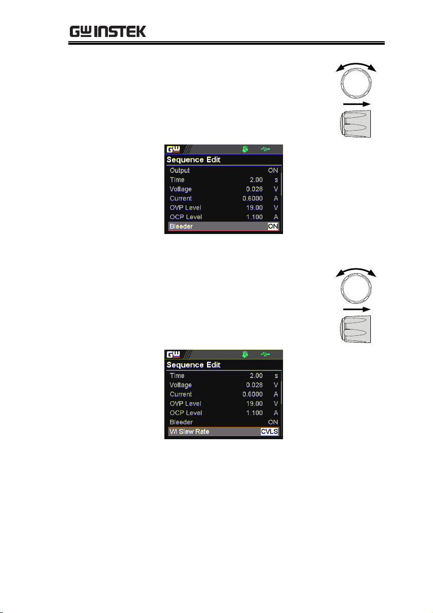
OPERATION
15. Scroll knob key to move to the
Bleeder field followed by clicking
knob key to enter the field. Scroll
knob key to turn on/off bleeder
followed by clicking knob key to
confirm bleeder action.
Bleeder
ON, OFF
16. Scroll knob key to move to the V/I
Slew Rate field followed by
clicking knob key to enter the field.
Scroll knob key to select an option
followed by clicking knob key to
confirm V/I slew rate setting.
V/I Slew Rate
CVHS, CCHS, CVLS, CCLS
89
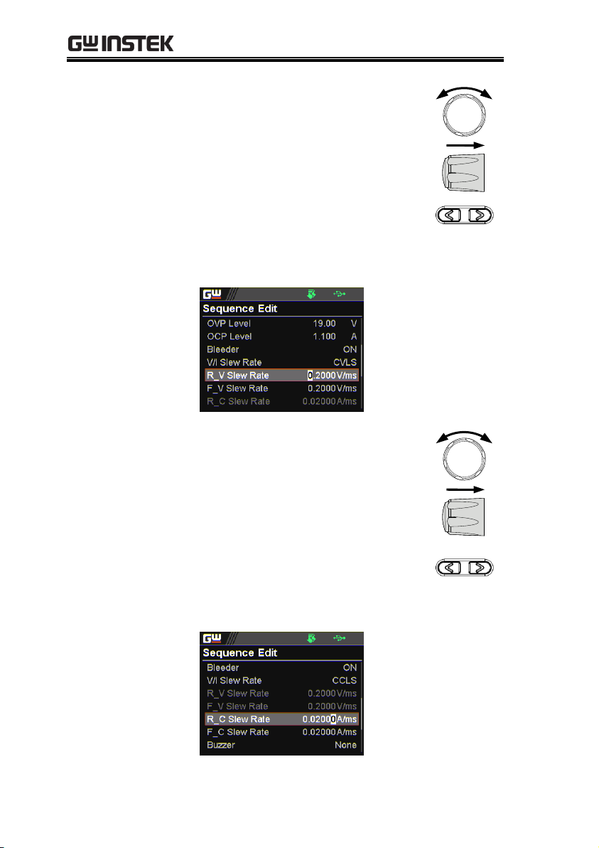
PPX Series User Manual
When CVLS is selected in previous
step, scroll knob key to R_V Slew
Rate and F_V Slew Rate fields
respectively followed by clicking
knob key to enter each field.
Scroll the knob key to adjust value,
along with the arrow keys to
change among digits followed by
clicking knob key to confirm set
value, respectively.
When CCLS is selected in previous
step, scroll knob key to R_C Slew
Rate and F_C Slew Rate fields
respectively followed by clicking
knob key to enter each field.
Scroll the knob key to adjust value,
along with the arrow keys to
change among digits followed by
clicking knob key to confirm set
value, respectively.
90
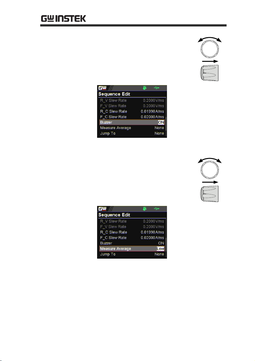
OPERATION
17. Scroll knob key to move to the
Buzzer field followed by clicking
knob key to enter the field. Scroll
knob key to turn on/off buzzer
followed by clicking knob key to
confirm buzzer setting.
Buzzer
ON, OFF
18. Scroll knob key to move to the
Measure Average field followed by
clicking knob key to enter the field.
Scroll knob key to select an option
followed by clicking knob key to
confirm the setting.
Measure Average
Off, Low, Middle, High
91

PPX Series User Manual
19. Scroll knob key to move to Jump
To field followed by clicking knob
key to enter the field. Scroll knob
key to select a step number along
with arrow keys to change among
digits followed by clicking knob
key to confirm step to jump to.
Jump To
1 ~ 20000
20. Scroll knob key to move to Jump
Count field followed by clicking
knob key to enter the field. Scroll
knob key to select a count number
along with arrow keys to change
among digits followed by clicking
knob key to confirm jump count.
Jump Count
1 ~ 10000
92

OPERATION
21. Scroll knob key to move to the
Trigger Out field followed by
clicking knob key to enter the field.
Scroll knob key to turn on/off the
function followed by clicking knob
key to confirm the selection.
Trigger Out
ON, OFF
22. Repeat the previous step 7 to step
21 for each step individually
within a sequence script.
93
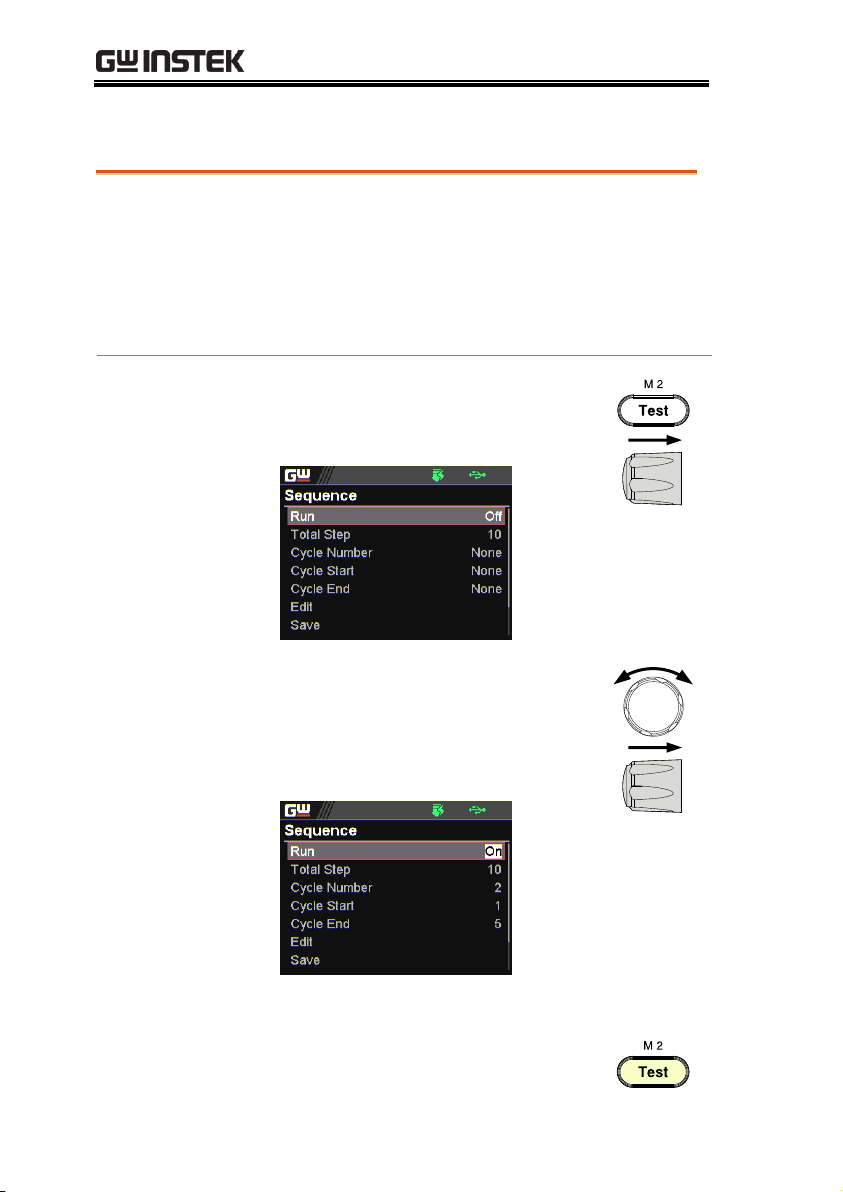
PPX Series User Manual
Overview
After well setting the relevant configurations
from Sequence and Sequence Edit pages, it is
ready to launch a sequence script test. Also, it is
available to load script from internal memory
or the connected USB disk. See page 98 for how
to load sequence script.
Steps
1. Press Test key followed by clicking
on Sequence field via knob key to
enter the Sequence page.
2. Scroll knob key to move to the Run
field followed by clicking knob key
to enter the field. Scroll knob key
to turn On followed by clicking
knob key to confirm setting.
Run
On, Off
3. The Test key will be illuminated in
yellow light on the front panel.
Run Sequence Script
94

OPERATION
4. Press the Test key to switch to
display mode in which press
Display key repeatedly until the V,
A and Sequence mode is shown.
The SEQ icon is displayed on the
top banner accordingly.
SEQ icon
Sequence
info section
5. Press the Output key to execute the
sequence script test. See the figures
below for descriptions on varied
conditions.
SEQ stop in
cycle mode
SEQ stop
Total step
Cycle
number
Cycle
start
Ongoing
cycle number
Ongoing
now step
SEQ run in
cycle mode
SEQ run
Total step
Cycle
number
Cycle
start
Ongoing
cycle number
Ongoing
now step
95

PPX Series User Manual
SEQ pause
in cycle
mode
SEQ pause
Total step
Cycle
number
Cycle
start
Ongoing
cycle number
Ongoing
now step
SEQ trigin
in cycle
mode
SEQ trigin
Total step
Cycle
number
Cycle
start
Ongoing
cycle number
Ongoing
now step
SEQ stop in
jump mode
SEQ stop
Total step
Ongoing
now step
SEQ run in
jump mode
SEQ run
Total step
Ongoing
now step
96

OPERATION
SEQ pause
in jump
mode
SEQ
pause
Total step
Ongoing
now step
SEQ trigin
in jump
mode
SEQ
trigin
Total step
Ongoing
now step
Note
When a script is running, pressing the Output key
will abort the execution of the script immediately.
The Output key illumination will turn off.
97
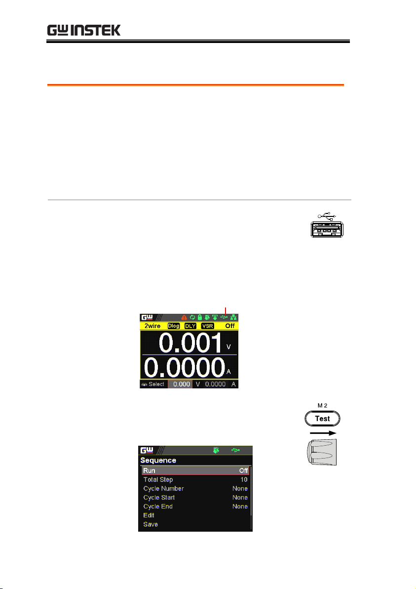
PPX Series User Manual
Overview
A sequence script can be loaded from either
USB disk or internal memory. When USB disk
is connected with PPX series, the script file in
USB disk has higher priority over internal
memory; that is, user can only load script file in
USB disk when USB disk is plugged in. Prior to
loading script from USB disk, ensure the script
file is placed in root directory.
Load script from
USB disk
1. Insert a USB disk into the front panel
USB-A port. Ensure the USB disk
contains a test script in root directory.
2. The icon of USB disk detection will be
displayed on the upper status bar after a few
seconds if the USB disk is recognized.
USB indicator
3. Press Test key followed by clicking
on Sequence field via knob key to
enter the Sequence page.
Load Sequence Script
98

OPERATION
4. Scroll knob key to move to the
Load field followed by clicking
knob key to enter the field. Scroll
knob key to select an available
script from USB disk.
(Format: S202_XXXX.csv).
5. The prompt window appears as
follows. Click knob key to confirm
loading the select script file.
Load script from
internal memory
1. Press Test key followed by clicking
on Sequence field via knob key to
enter the Sequence page.
99

PPX Series User Manual
2. Scroll knob key to move to the
Load field followed by clicking
knob key to enter the field. Scroll
knob key to select an available
script from internal memory
(Format: tXXX.csv).
3. The prompt window appears as
follows. Click knob key to confirm
loading the select script file.
100
 Loading...