

Page 1

Programmable High Precision DC
Power Supply
PPH-1503
User Manual
GW INSTEK PART NO. 82PH-15030E01
ISO-9001 CERTIFIED MANUFACTURER
Page 2

Copyright Statement
This manual contains proprietary information, which is protected by
copyright. All rights are reserved. No part of this manual may be
photocopied, reproduced or translated to another language without
prior written consent of Good Will company.
The information in this manual was correct at the time of printing.
However, Good Will continues to improve products and reserves the
rights to change specification, equipment, and maintenance
procedures at any time without notice.
Good Will Instrument Co., Ltd.
No. 7-1, Jhongsing Rd., Tucheng Dist., New Taipei City 236, Taiwan.
Page 3

TABLE OF CONTENTS
Table of Contents
SAFETY INSTRUCTIONS ................................................... 5
OVERVIEW ...................................................................... 11
Introduction ................................................... 11
Key Features ................................................... 13
Operating Principals ....................................... 15
Front Panel ..................................................... 17
Rear Panel ...................................................... 23
Constant Voltage/Constant Current Crossover
Characteristics................................................ 25
GETTING STARTED ......................................................... 27
Start Up .......................................................... 27
DVM and Load Connection ............................. 28
Turning the Output On/Off............................. 29
BASIC OPERATION ......................................................... 31
Basic Power Supply Functions ........................ 31
DVM ............................................................... 41
Pulse Current Measurement ........................... 43
Long integration ............................................. 49
Current Sink Function ..................................... 54
External Relay Control .................................... 56
Save/Recall ..................................................................... 59
Save Settings .................................................. 59
Recall Settings ................................................ 60
Restore Factory Default Settings ..................... 63
3
Page 4

PPH-1503 User Manual
System Settings .............................................................. 64
System Information ........................................ 64
Utilty Settings ................................................. 65
REMOTE CONTROL ........................................................ 67
Remote Control .............................................. 67
Command Syntax ............................................ 76
Command List ................................................ 80
Command Details ........................................... 85
SCPI Status Registers SCPI ........................... 121
Errors ........................................................... 129
APPENDIX ..................................................................... 133
Replacing the Fuse ....................................... 133
Specifications ............................................... 134
Optional Accessories .................................... 136
Declaration of Conformity ............................ 137
4
Page 5
SAFETY INSTRUCTIONS
WARNING
Warning: Identifies conditions or practices that
could result in injury or loss of life.
CAUTION
Caution: Identifies conditions or practices that
could result in damage to the PSW or to other
properties.
DANGER High Voltage
Attention Refer to the Manual
Protective Conductor Terminal
Earth (ground) Terminal
SAFETY INSTRUCTIONS
This chapter contains important safety instructions
that you must follow during operation and storage.
Read the following before any operation to insure your
safety and to keep the instrument in the best possible
condition.
Safety Symbols
These symbols may appear in the manual or on the instrument.
5
Page 6

PPH-1503 User Manual
Do not dispose electronic equipment as unsorted
municipal waste. Please use a separate collection
facility or contact the supplier from which this
instrument was purchased.
6
Page 7

SAFETY INSTRUCTIONS
General
Guideline
CAUTION
Do not place any heavy object on the unit.
Avoid severe impact or rough handling that
leads to damaging the unit.
Do not discharge static electricity to the unit.
Do not block the cooling fan opening.
Do not perform measurements on circuits that
are directly connected to mains power.
Do not disassemble the PSW unless you are
qualified.
(Measurement categories) EN 61010-1:2001 specifies the
measurement categories and their requirements as follows. The
PPH-1503 falls under category I.
Measurement category IV is for measurement performed at the
source of low-voltage installation.
Measurement category III is for measurement performed in the
building installation.
Measurement category II is for measurement performed on the
circuits directly connected to the low voltage installation.
Measurement category I is for measurements performed on
circuits not directly connected to Mains.
Power Supply
WARNING
AC Input voltage range: 90VAC~264VAC
Frequency: 50Hz/60Hz
To avoid electrical shock connect the protective
grounding conductor of the AC power cord to
an earth ground.
Safety Guidelines
7
Page 8

PPH-1503 User Manual
Fuse
WARNING
Fuse type: T2.0A/250V
To prevent fire, replace the fuse only with the
specified type and rating.
Disconnect the power cord before replacing the
fuse.
Make sure the cause of fuse blowout is fixed
before replacing the fuse.
Cleaning the
power supply
Disconnect the power cord before cleaning the
oscilloscope.
Use a soft cloth dampened in a solution of mild
detergent and water. Do not spray any liquid
into the oscilloscope.
Do not use chemicals containing harsh products
such as benzene, toluene, xylene, and acetone.
Operation
Environment
Location: Indoor, no direct sunlight, dust free,
almost non-conductive pollution (Note below)
Relative Humidity: < 80%
Altitude: < 2000m
Temperature: 0°C to 40°C
(Pollution Degree) EN 61010-1:2001 specifies pollution degrees and
their requirements as follows. The PPH-1503 falls under degree 2.
Pollution refers to “addition of foreign matter, solid, liquid, or
gaseous (ionized gases), that may produce a reduction of dielectric
strength or surface resistivity”.
Pollution degree 1: No pollution or only dry, non-conductive
pollution occurs. The pollution has no influence.
Pollution degree 2: Normally only non-conductive pollution
occurs. Occasionally, however, a temporary conductivity caused
by condensation must be expected.
Pollution degree 3: Conductive pollution occurs, or dry, non-
conductive pollution occurs which becomes conductive due to
condensation which is expected. In such conditions, equipment
is normally protected against exposure to direct sunlight,
precipitation, and full wind pressure, but neither temperature
nor humidity is controlled.
8
Page 9

SAFETY INSTRUCTIONS
Storage
environment
Location: Indoor
Relative Humidity: < 70%
Temperature: -10°C to 70°C
9
Page 10

PPH-1503 User Manual
Green/ Yellow:
Earth
Blue:
Neutral
Brown:
Live (Phase)
Power cord for the United Kingdom
When using the power supply in the United Kingdom, make sure the
power cord meets the following safety instructions.
NOTE: This lead/appliance must only be wired by competent persons
WARNING: THIS APPLIANCE MUST BE EARTHED
IMPORTANT: The wires in this lead are coloured in accordance with the following
code:
As the colours of the wires in main leads may not correspond with the coloured
marking identified in your plug/appliance, proceed as follows:
The wire which is coloured Green & Yellow must be connected to the Earth
terminal marked with either the letter E, the earth symbol or coloured
Green/Green & Yellow.
The wire which is coloured Blue must be connected to the terminal which is
marked with the letter N or coloured Blue or Black.
The wire which is coloured Brown must be connected to the terminal marked
with the letter L or P or coloured Brown or Red.
If in doubt, consult the instructions provided with the equipment or contact the
supplier.
This cable/appliance should be protected by a suitably rated and approved HBC
mains fuse: refer to the rating information on the equipment and/or user
instructions for details. As a guide, a cable of 0.75mm2 should be protected by a
3A or 5A fuse. Larger conductors would normally require 13A types, depending
on the connection method used.
Any exposed wiring from a cable, plug or connection that is engaged in a live
socket is extremely hazardous. If a cable or plug is deemed hazardous, turn off
the mains power and remove the cable, any fuses and fuse assemblies. All
hazardous wiring must be immediately destroyed and replaced in accordance to
the above standard.
10
Page 11

OVERVIEW
Overview
The PPH-1503 is a portable high-speed
programmable DC power supply with flexible
operating configurations. In addition to the basic
power supply functionality, it is also able to
measure pulse current and the average current
over long periods of time.
The PPH-1503 is designed for testing the power
consumption of battery powered wireless
communication devices (e.g. cell phones). Such
devices often have large load variations within a
short time span. The high precision power supply
has excellent voltage stability during pulsed loads
and is capable of simultaneously measuring the
pulse current, even for very short pulses. In
addition, the power supply is able to sink current,
allowing it to simulate the characterics of a
discharged rechargeable battery for testing
chargers and charge control circuits.
OVERVIEW
This chapter contains a brief introduction to PPH-1503,
the main features, as well as an overview of the front
and rear panel. Use the Getting Started chapter on
page 27 to for start up instructions and how to setup
the appropriate operation environment.
Introduction
11
Page 12

PPH-1503 User Manual
Basic Power
Supply Function
The PPH-1503 works as a conventional power
supply with automatic CC/CV crossover.
Parameters such as the output voltage, current,
read back refresh rate, data sampling period,
power-on status, OVP and current range can be
configured using the control panel. The voltage
and current settings and the actual voltage/current
are displayed on the LCD. For details, see page 31.
Pulse Current
Measurement
Function
The PPH-1503 can measure the change in
instantaneous current and the current of extremely
short pulses. The readback refresh rate, data
sampling period, trigger delay and trigger level
can be set by the front panel keys and is displayed
on the LCD. For details see page 43.
Current
Measurement
over Long Periods
This function can measure the average current of
one or more pulses. The readback refresh rate,
trigger mode, and trigger timeout and trigger level
settings are controled by the front panel keys and
is displayed on the LCD display. For details, see
page 49.
Current Sink
Features
When the voltage of an external power source is
greater than the high-speed power supply output,
the system will automatically work as an electronic
load to sink current. For details, see page 54.
Digital Volt
Meter
The PPH-1503 has a DVM function that can
measure DC voltages in the range of 0~20VDC. For
details, see page 41.
Remote Control
To meet the various needs of customers, the PPH1503 is designed for USB, GPIB and LAN remote
control. For details, see page 67.
12
Page 13

OVERVIEW
Additional
Features
The PPH-1503 has external relay control signals for
customers. The relay control signals are synced to
the pulse current measurement feature. For details,
see page 56.
Features
Low noise: Thermostatically controled fan.
Compact, lightweight.
3.5 inch TFT display.
Operation
Constant voltage and constant current operation
(CV/CC).
Output on/off control.
Front and Rear output control key.
Digital panel control.
5 groups of save/recall settings and 10
automatically generated power-on settings.
Digital voltage and current settings.
Software calibration.
Alarm buzzer.
Key lock function.
Protection
Features
Reverse polarity protection.
Overvoltage and overcurrent protection
(OVP/Trip).
Overtemperature protection (OTP).
Key Features
13
Page 14

PPH-1503 User Manual
Interface
USB remote control.
GPIB remote control.
LAN remote control.
14
Page 15

OVERVIEW
Overview
The PPH-1503 mainly consists of the follow
components:
AC to DC Switching power supply
DC to DC Buck converter circuit
Precision output control circuit
The block diagram below shows a function
description of each of the circuits. The following
page will show detailed decriptions of each
component.
Block Diagram
AC INPUT
AC TO DC
SWITCH POWER
DC TO DC
BUCK CIRCUIT
U201,Q201,Q202
L202
LINEAR
CONTROL
Q306~Q308,U303
ON/OFF SWITCH
Q309,Q310,
Q315,Q316
AUXILIARY
POWER SUPPLY
U101,T101,
Q102~Q105
V-SET
I-SET
AND
VOLTAGE
COMPARATOR
U301A
VOLTAGE
SAMPLING
CIRCUIT
U401,U402
CURRENT
COMPARATOR
U301B
CURRENT
SAMPLING
CIRCUIT
U430
SAMPLE
RESISTANCE
R366,R366A
R367,R367A
OUTPUT
Swtiching Power
Supply
AC power is converted to 24VDC by the switch
mode power supply module.
DC Down
Conversion
To reduce the input voltage to 24VDC (slightly
higher than the settable voltage) the U201 Buck IC
is used in conjunction with two power MOSFETS
(Q201/Q202) and an inductor (L202).
Operating Principals
15
Page 16

PPH-1503 User Manual
Linear Output
Circuit (Linear
Regulator)
The Q306, Q307 dividers reduce the heat on a
single component. The U303, U301, U403, U401
and U402 components form a control circuit to
achieve accurate output.
Auxillary Power
Supply
The independent auxillary DC power supply is
achieved with the U101, T101 and Q102~Q105
components.
16
Page 17
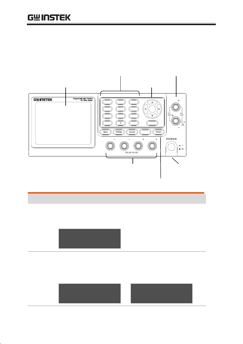
Front Panel
PPH-1503
LCD display
Numberpad and
secondary function keys
Arrow keys
DVM inputs
Front panel output
terminals
Function keys
Power button
Display
Voltmeter
Indicators
Displays the output voltage with up to 5 digits of
resolution. The default units are Volts (V).
15.000 v
Ammeter
Indicator
Displays the output current with up to 5 digits of
resolution, depending on the current range (5A/5mA).
The current range is selectable between A and mA.
5.0000 A
or
5.0000 mA
OVERVIEW
17
Page 18

PPH-1503 User Manual
Setting
Display
Displays the voltage and current settings.
V-Set
15.000 V
I-Set
5.0000 A
Parameter
Settings
Display
Displays the parameter settings. For details on setting
parameters, see page 20. The following figure shows the
F1 parameter settings (V AND I), for example.
Status
Display
Display the current status of the instrument.
Status
Output mode
CV mode:
C V
CC mode:
C C
Overvoltage protection
Enabled:
O.V.P
Disabled:
O.V.P
Alarm
Enabled:
BEEP
Disabled:
BEEP
Key lock
Locked:
LOCK
Unlocked:
LOCK
CurrRange: 5 A LimMode: Limit
PowOnSetup: RST OutputRelay: One
O.V.P: Off RecallSetup: ---
IntRate: 1.00 PLC AverRead[1][2]: 1
18
Page 19

OVERVIEW
Remote connectivity
Local mode:
RMT
Remote:
GPIB LAN
USB
Output
Switching the Output Source
Front:
FRONT
Rear:
REAR
Output State
On:
ON
Off:
OFF
Function
Display
Displays the unit functions. There four functions:
F1: Basic power supply function (V AND I);
F2: Digital Voltmeter function (DVM);
F3: Pulse current meter function (PULSE);
F4: Long integration current measurement function
The basic power supply function is shown below. (The
active function is shown in yellow.)
Function
Keys
Menu key
Menu key to enter or exit from
system settings.
Voltage
Setting key
Press the Voltage key to set the
voltage settings. See page 34 for
operation details.
19
Page 20
PPH-1503 User Manual
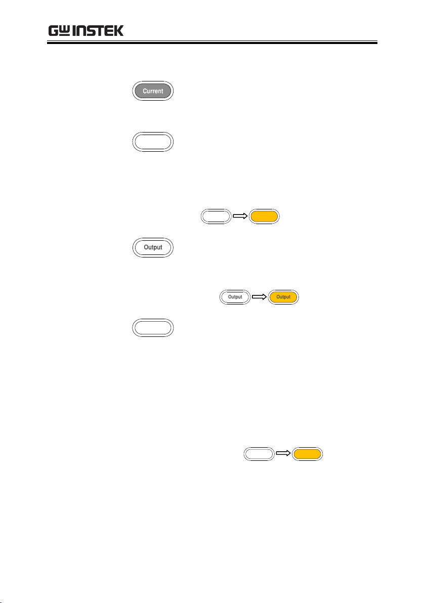
Current
Setting key
Press the Current key to set the
current settings. See page 35 for
operation details.
Front and
Rear output
toggle key
Front and rear output toggle
switch. The key will be lit when
the output is set to the rear
outputs.
Rear panel output:
Output key
The Output key turns the output
on or off. The Output key will
lightup when the output is on.
On:
LOCK key
The Lock key is used to disable all
the panel keys except for the
Output key. Pressing the Lock key
for at least 2 seconds will turn the
panel lock on or off. The Lock key
can also be used to exit from
remote control mode. When the
panel lock is active the Lock key
will light up.
Locked:
20
Page 21

OVERVIEW
Numberpad
a. The numberpad is used to enter
various parameters and values.
The Clear key can be used to clear
set parameters.
b. F1/F2/F3/F4 function short
cuts. Press any of the function
short cuts when in the main menu
to enter the corresponding
function interface.
F1: Basic power supply function
F2: Digital voltmeter function
F3: Pulse current meter function
F4: Long integration current
measurement function.
c. H/L/A Pulse current
measurement shortcut keys. These
short cut keys only work in the
Pulse current measurement main
menu.
H: High measurement mode
L: Low measurement mode
A: Average measurement mode
Directional
keys and
Enter key
The directional keys are used for
parameter and menu selection as
well for fine adjustment of the
current/voltage settings.
The Enter key is used to confirm
the selection of any settings or
parameters and to exit after a
setting is complete.
21
Page 22
PPH-1503 User Manual
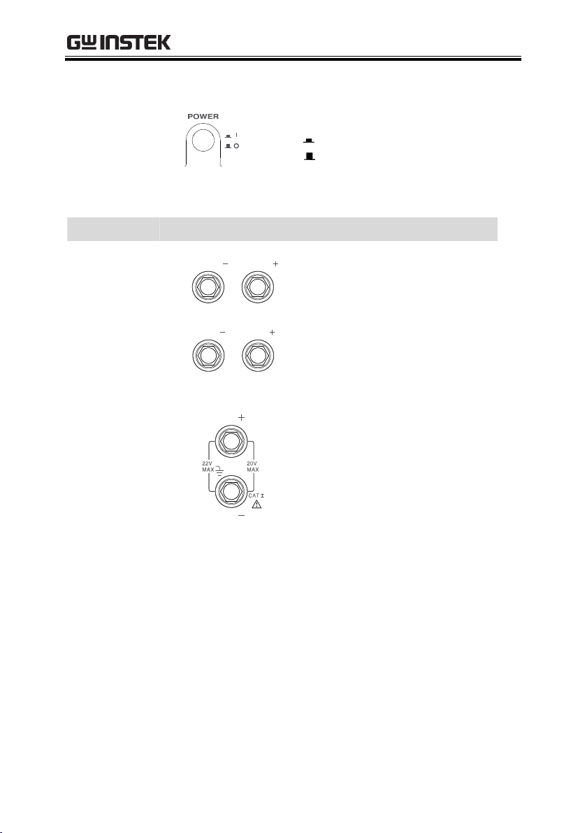
Power Button
Turns the power on or off.
On:
Off:
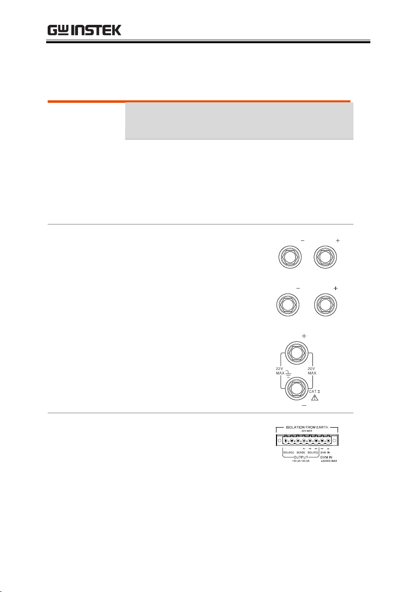
Terminals
Output
Terminals
(SOURCE)
Output source terminals.
Voltage
Feedback
Terminals
(SENSE)
Sense terminals.
Voltmeter
Terminals
(DVM)
Digital voltmeter input
terminals.
22
Page 23

Rear Panel
AC power socket
and fuse
Rear panel outputs and
DVM inputs
External
control port
Lan port
USB port
GPIB port
Heat sink fan
Terminals
AC input
socket and
line fuse
The AC input:
90~264VAC, 50Hz/60Hz
Fuse: 2A slow-blow type. See page
133 for details.
USB port
USB device port for remote
control. See page 67 for details.
GPIB port
GPIB slave port for remote control.
Abides to IEEE488.1 (SCPI)
protocol. See page 69 for details.
LAN port
LAN port for remote control. See
page 72 for details.
OVERVIEW
23
Page 24
PPH-1503 User Manual
Output
interface
A total of 8 ports: 2 positive output
terminals, 2 negative output
terminals, a Sense+ terminal, a
Sense- terminal, a DVM- input
terminal and a DVM+ input
terminal. Refer to the printed label
under the terminals for the specific
order of the terminals.
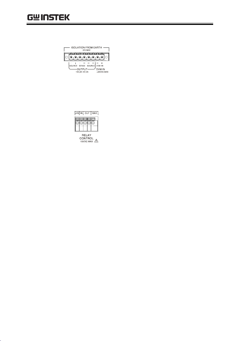
Relay control
interface
A total of 5 ports: A +5V input
terminal, a ground terminal and 2
terminals for relay control. See
page 56 for relay control details.
24
Page 25

OVERVIEW
Background
The unit will switch automatically between
constant voltage and constant current according to
changes in the load.
CV mode
When the load current is less than the current
setting, the unit operates in constant voltage mode,
changing the current level according to the load
but maintaining the set voltage level until the
current reaches the set current level. The status
indicator will show CV on the LCD when in CV
mode.
Constant Current
Mode
When the output current reaches the set current
level, the unit switches operation to constant
current mode. The status indicator will show CC
on the LCD display. In CC mode, the current level
is maintained and the voltage level is limited to
less than the set voltage level to limit the output
power from an overload. When the current drops
below the set current level, the unit will revert
back to CV mode.
Constant Voltage/Constant Current Crossover Characteristics
25
Page 26

PPH-1503 User Manual
Diagram
Vmax
Imax
Constant
Voltage
Constant
Current
Vout
Iout
26
Page 27

GETTING STARTED
Checking the AC
Voltage
Before the power is turned on,
confirm that the input power
supply meets the following
conditions:
90-264VAC, 50Hz/60Hz
Connecting the
AC power cord
The fuse is a 2A slow-blow fuse.
Confirm that the fuse is of the
correct type and rating before
connecting the power cord.
Turning the
power on
Press the power button. The
LCD will display the line
frequency of the AC power
supply.
Turning the
power off
To turn the power off, press the
power button again.
GETTING STARTED
This chapter describes the start up procedures and the
preparation that is necessary before operating the
power supply.
Start Up
27
Page 28
PPH-1503 User Manual
Recommended
Cables
Model
Specification
Usage
GTL-117
10A
Front panel DVM input
GTL-204A
10A
Front panel Source
terminal
GTL-203A
3A
Front panel Sense
terminal
Front panel
wiring
Use the GTL-204A cables for the
front panel source connections.
Use the GTL-203A cables for the
sense connections.
Use the GTL-117 cables for the
DVM connections.
Rear panel
connections
Rotate the screws counter
clockwise to loosen the ports.
Insert the wires into the
appropriate terminal according
to the labels printed under the
terminals.
DVM and Load Connection
28
Page 29

GETTING STARTED
Screw the terminals in a
clockwise direction to tighten.
Note
For safety considerations, please keep in mind that the
front panel and rear panel terminals are physically
connected.
Wire Gauge
Load wires must have enough current capacityto
minimize cable loss and load line impedance.
Voltage drop across a wire should not excess 0.5V.
The following list is the wire current rating at
450A/cm2.
Wire Size(AWG)
Maximum Current (A)
20
2.5 18
4
16
6
14
10 12
16
Panel Operation
Press the Output key to
turn the output on. The
Output key will light-up
when the output is on.
The status display on the
LCD display will also turn
on.
OFF
ON
Turning the Output On/Off
29
Page 30

PPH-1503 User Manual
When the output is turned on, pressing the Output
key again will turn the output off. When the
output is off, the Output key will no longer be
illuminated and the status on the LCD display will
revert back to the OFF status.
Automatic
Output Shut
Down
Any of the following actions will cause the output
to be automatically shut down:
If any of the setups are recalled.
OVP/OTP protection is tripped.
OCP protection is tripped.
30
Page 31

BASIC OPERATION
Description
The PPH-1503 operates as a generic power supply
with the ability to display different current ranges.
The output can be toggled between the front and
rear outputs using the Rear key. When the Rear
key is lit, it indicates that the rear panel output is
active and that the front panel output is off.
Parameter
Description
IntRate
The data sampling period derived
from the number of power line
cycles.
The setting range is:
0.1PLC to 10.00PLC (power line
cycles)
1PLC = 16.7ms(60Hz)/20ms(50Hz).
*PLC stands for power line cycles.
BASIC OPERATION
This chapter describes how to set various functions.
Basic Power Supply Functions
31
Page 32

PPH-1503 User Manual
AverRead[1][2]
Readback refresh rate. This will
display the average number count.
The settings for parameters[1][2] are
shared, the remaining parameters
[3][4] are set in their corresponding
menus.
[1] Power Supply functions
[2] DWM function.
[3] Pulse current measurement
[4] Long integration current
measurement
CurrRange
The current range selection has
three settings: 5A, 5mA and Auto.
The 5mA range only accepts a
current setting 1A or less. If the
5mA range is selected and if the
current setting is greater than 1A,
the setting value is automatically
reduced to 1A.
32
Page 33

BASIC OPERATION
LimMode
Current limiting mode
There are 4 settings for the current
limiting mode:
Limit, Trip, LimitRelay, Trip Relay.
The Limit settings will limit the
current. When the current reaches
the setting value, the current
remains constant, as in CC mode.
The Trip setting will turn the output
off when the current limit has been
reached.
See page 56 for details on the Limit
Relay and Trip Relay settings.
PowoOnSetup
Power on settings have 11 settings:
Rst/SAV0 ~ SAV9
See page 60 for further details.
RelayControl
The relay control settings have 2
configurations:
Zero/One
See page 56 for further details.
O.V.P
The overvoltage settings have a
setting range of 0.05 to 15.20V or
OFF.
RecallSetup
There are 6 sets of save/recall
memories.
Rst/ SAV0 to SAV4
33
Page 34

PPH-1503 User Manual
Output Range
Voltage
0.000V~15.000V
Current
0.0000A~3.0000A (0V~15V)
0.0000A~5.0000A (0V~9V)
Parameter
Settings
Voltage
Press the Voltage key
and the voltage setting
on the LCD is
activated. A yellow dot
appears under the
current digit.
V-Set
00.500 V
(a)Use the number pad (keys: 0~9,
Clear) to set the voltage value and
then press the Enter key.
To enter 12.345V:
The input dialog box appears on
the LCD:
12.345
34
Page 35

BASIC OPERATION
(b)Step Setting:
Press the left and right
arrow keys ( , ) to
fine tune the voltage
setting at the digit
level. The selected digit
will have a yellow dot
directly underneath.
Press the up and down
arrow keys ( , )
to adjust the selected
digit. Press the Voltage
key again to finish and
exit setting the voltage.
Current
Press the Current key
and the current setting
on the LCD is
activated. A yellow dot
appears under the
current digit.
I-Set
2.000 A
(a)Use the number pad (keys: 0~9,
Clear) to set the current value and
then press the Enter key.
To enter 1.2345A:
The input dialog box appears on
the LCD:
1.2345
35
Page 36

PPH-1503 User Manual
Press the left and right
arrow keys ( , ) to
fine tune the current
setting at the digit
level. The selected digit
will have a yellow dot
directly underneath.
Press the up and down
arrow keys ( , )
to adjust the selected
digit. Press the Current
key again to finish and
exit setting the current.
IntRate
Use the arrow keys to select IntRate
and press Enter. Input the
parameters and press Enter to save.
Range: 0.1 to 10.00
AverRead[1][2]
Use the arrow keys to select
AverRead[1][2] and press Enter. Input
the parameters and press Enter to
save.
Range: 1 to 10
CurrRange
Use the arrow keys to select
CurrRange and press Enter to go the
the CurrentRange menu. Input the
current range using the up and
down arrow keys. Press Enter to
save.
36
Page 37

BASIC OPERATION
LimMode
Use the arrow keys to select LimMode
and press Enter to go to the Current
Lim menu. Select the Current Lim
mode using the up and down arrow
keys. Press Enter to save.
See page 56 for further details.
PowOnSetup
Use the arrow keys to select
PowOnSetup and press Enter to go to
the Power On Setup menu. Use the
up and down arrow keys to select
the power on setting. Press Enter to
save.
See page 60 for further details.
RelayControl
Use the arrow keys to select
RelayControl and press Enter. Use the
up and down arrow keys to set the
type of relay control. Press Enter to
save.
See page 56 for further details.
O.V.P
Use the arrow keys to select O.V.P
and press Enter. Input the OVP
setting and press Enter to save.
RecallSetup
Use the arrow keys to select
RecallSetup and press Enter to go to
the Recall Setup menu. Use the
arrow keys select a stored setup.
Press Enter to confirm the recall.
See page 60 for further details.
37
Page 38

PPH-1503 User Manual
Note:
1. The
Clear
key can be used to clear numbers that
have already been entered.
2. Voltage and current parameter values use stepped
input values. All other numerical parameters can use
the number pad to enter parameter values.
Operation
REAR /
FRONT
After setting all the parameters the
Rear key can be used to set the
output to the front or rear output
terminals.
Pressing the Rear key will toggle the
output between the front and rear
terminals.
When set to rear, the Rear key will
light up and REAR will appear in the
status bar on on the LCD.
When set to front, the Rear key will
not be lit and FRONT will appear in
the status bar on the LCD.
REAR
FRONT
38
Page 39

BASIC OPERATION
Output
Press the Output key to turn the
output on. When the output is on, the
Output key will light up and ON (in
green) will be shown in the status bar
on the LCD.
When the output is off, the Output
key will not be lit and OFF (in red)
will be shown in the status bar on the
LCD.
ON
OFF
Status
Description
CV/CC
These two icons represent
the output states of the
power supply:
CV appears in yellow when
the power supply is in
constant voltage mode.
CC appears in red when the
power supply is in constant
current mode.
C V C C
O.V.P
OVP will appear in yellow
when the OVP has not been
tripped.
The OVP icon will turn red
when the OVP has tripped.
When the OVP protection
has not been activated, it
will be greyed-out.
O.V.P
O.V.P
O.V.P
39
Page 40

PPH-1503 User Manual
BEEP
When the beeper setting is
activated, the BEEP icon will
be shown in yellow.
When the beeper settings is
turned off, it will be greyedout.
BEEP
BEEP
LOCK
When the panel lock is
activated, the lock icon will
be shown in red.
When the panel lock is
turned off, the lock icon is
greyed-out.
LOCK
LOCK
RMT
In the remote control display
area, RMT will be shown in
grey when reomote control
is disabled.
When GPIB remote control is
active, a red GPIB icon is
shown. When LAN remote
control is active, a red LAN
icon is shown and when USB
remote control is active, a
red USB icon is shown.
RMT
GPIB
LAN
USB
40
Page 41

BASIC OPERATION
REAR/
FRONT
When the output is set for
the rear panel terminals,
REAR is displayed in
yellow.
When the output is set for
the front panel, FRONT is
displayed in yellow.
REAR
FRONT
ON/OFF
When the output is off, OFF
in displayed.
When the output is on, ON
is displayed.
OFF
ON
Description
The PPH-1503 has a separate digital voltmeter
with a measurement range of 0~+20VDC. When
using the voltage meter, the power supply must be
properly grounded.
Parameter
Description
Intrate
Sets the reading rate of DVM
measurements based on the number
of PLCs.
0.01PLC~10.00PLC.
1PLC=16.7ms(60Hz)/20ms(50Hz).
*PLC stands for Power Line Cycle
DVM
41
Page 42

PPH-1503 User Manual
AverRead[1][2]
The number of samples used to
calculate the average. The AverRead
setting for the power supply
functions[1] and the DVM
functions[2] are shared.
Note:
[1]: Power supply functions
[2]: DVM function
[3]: Pulse current measurement
function
[4]: Long Integration current
measurement function
RecallSetup
There are 6 sets of save/recall
memories.
Rst/ SAV0 to SAV4
Parameter
Setttings
IntRate
Use the arrow keys to select IntRate
and press Enter. Input the
parameters and press Enter to
save.
Range: 0.01 to 10.00
AverRead[1][2]
Use the arrow keys to select
AverRead[1][2] and press Enter. Input
the parameters and press Enter to
save.
Range: 1 to 10
42
Page 43

BASIC OPERATION
Recall Setup
Use the arrow keys to select
RecallSetup and press Enter. Use the
arrow keys select a stored setup.
Press Enter to confirm the recall.
See page 60 for further details.
Operation
The unit switches to DWM mode
automatically when the DVM
inputs are used. Using the DVM
meter function doesn’t affect the
operation of the power supply.
The DMV function works with the
output on or off.
Connection
For the connection details for the front and rear
terminals, please page 28.
Description
Changes in the load current allows us to measure
the pulse current.
There are three ways that pulse current can be
measured:
1. Measuring the peak current over a single cycle
(High Measurement).
2. Measuring the trough current over a single cycle
(Low Measurement).
3. Measuring the average current over a single
cycle (Average Measurement).
Pulse Current Measurement
43
Page 44

PPH-1503 User Manual
The high and average measurements are triggered
by the rising edge of the pulse current are
performed for the time specified for the
measurement.
Low measurement is triggered by the falling edge
of the pulse current.
Note: Pulse current measurement is only valid up
to 5A.
Parameter
Description
IntTime
Integration Time.
The integration measurement time
can be set to automatic or to one of
the manual settings (High Time,
Low Time, Aver Time).
When the integration
measurement time is set to
automatic mode, the system will
measure the peaks and troughs of
the pulse current and will
automatically set an appropriate
intergration time. The average
integration time is the time of all
the accumulated peaks and
troughs. After the setting the
integration time to automatic, the
setting will apply to all subsequent
pulse measurements, unless the
automatic integration mode is
applied again or the integration
time is manully set. The automatic
44
Page 45

BASIC OPERATION
Integration time can automatically
detect pulses in the 80uS to 833mS
range.
The manual time range setting is
33uS to 833333uS. The default
units are in microseconds (uS). The
unit will automatically round
down the last two digits to 00, 33
or 66 micoseconds. For example,
for a value of 65.999, it will be
rounded down to 33 and 66.01 will
be rounded down to 66.
TrigDelay
Trigger Delay
When a pulse is detected, there
will be a 25us code execution
delay time. The trigger delay
settings are used to filter out the
current overshoot. Measurement
will begin from after the trigger
delay time. The trigger delay
setting range is: 0~0.10000S, with a
resolution of 0.00001S. The setting
units are in seconds.
AverRead[3]
Average Reading Count: Reads
back the average number of
displayed values.
This parameter is only applicable
for pulse current measurement.
The average number range can set
from 1 ~ 100 with a resolution of 1.
45
Page 46

PPH-1503 User Manual
TrigLeve[3]
Trigger Level.
To avoid false pulse
measurements, the trigger level
can be set close to the current
amplitude. All noise and transient
currents that are below the trigger
level will be ignored. The trigger
level has a setting range of 0 to 5A,
with a resolution of 5mA. The
setting unit for the trigger level is
in amps (A). This setting is only
valid for pulse measurements.
RecallSetup
Recalls stored settings. A total of 6
settngs can be recalled:
RST/SAV0 to SAV4
Parameter
Settings
IntTime
Use the arrow keys to select IntTime,
press Enter and then use the arrow
keys to select the type of integration
time that you want to set (Hight
Time, Low Time, Aver Time). Press
Enter again to set the integration
time. After inputing the integration
time, press Enter to return to the
pulse current measurement menu. If
Auto Time was selected, press Enter to
return to the pulse current
measurement menu.
Example:
High Time 33uS: IntTime
Hight Time
using the
46
Page 47

BASIC OPERATION
numberpad enter 33
.
The time range can be set between
33uS and 833333uS. The setting units
are in microseconds (uS).
TrigDelay
Use the arrow keys to select TrigDelay,
press Enter and input the delay. Press
Enter again to confirm.
The TrigDelay has a settable range of
0~0.10000S. The setting units are in
seconds (S).
AverRead[3]
Use the arrow keys to select
AverRead[3], and then press Enter. Input
the AverRead number and then press
Enter again to confirm.
The AverRead setting has a settable
range of 1~00.
TrigLeve[3]
Use the arrow keys to select TrigLeve[3]
and press Enter. Input the trigger
level and press Enter again to
confirm.
The TrigLeve parameter has a
settable range of 0~5.000A. The
setting units are in amperes (A).
RecallSetup
Use the arrow keys to select RecallSetup
and press Enter to go the Recall Setup
menu. Use the arrow keys to a setup.
Press the Enter key to confirm. See
page 60 for further details.
47
Page 48

Panel Operation
Output
Press the Ouput key.
When the Output key is
lit, pulse current
measurement is active.
When no pulse current is
detected, NO PULSE will
be dispalyed in red on the
LCD screen. The unit will
wait until the next pulse is
detected.
The measurement
settings can be
edited during
measurement. The
H, L, A keys on the
keypad can be
used to perform
fast-switching
between
measurement
modes.
HIGH
LOW
AVER
Note
The LCD display
will indicate which
measurement
mode is active with
an orange line
under the active
mode for HIGH,
LOW or AVER.
HIGH
NO PULSE
PPH-1503 User Manual
48
Page 49

BASIC OPERATION
Description
The long current integration measurement function
measures the mean (average) current over a single or
multiple current pulses. The long integration time
period must be a full period or integer multiples of a
complete period of the measured pulse current. The
Long integration measurement calculates the whole
integration time as an integer number of integration
cycles. An integration cycle is the line cycle period plus
the data processing time.
For example, if the line frequency is 60Hz, then a single
integration cycle is 16.7mS, if the frequency is 50Hz,
then a single integration cycle is must be 20mS. Long
integraton is one of the methods to extend A/D circuits
to exceed beyond their maximum integration time. The
A /D conversion circuits can measure a pulse of up to
833 mS. Long integration measurement extends the
A/D integration time to achieve a longer pulse
measurement. This can extend the measurement time
for long integration to a maximum of 60S.
Note: When this feature is used, the current range is
set to 5A.
Long integration
49
Page 50

Parameter
Description
IntTime
Integration time
The integration time can be set
manually or automatically by the
operator. For manual settings, the
integration time can be set to a
maximum of 60 seconds. For a line
frequency of 60Hz the minimum
integration time is 850mS with a step
resolution of 16.7mS. For a line
frequency of 50Hz, the minimum
integration time is 840mS with a step
resolution of 20mS.
When the integration time is set to Auto
Time, the system will automatically
measure the time between two adjacent
rising edges and an appropriate
integration time is set for the peak and
trough. If there are more than two
pulses, the integration time must be set
manually.
TrigEdge
Trigger edge
Pulse edges are used to trigger long
integration measurement. Regardless of
whether a rising or falling edge is used
as a trigger, a pulse must furst be
detected before measurement can start.
Measurement can also start without an
edge trigger. When Trig On Neither is
selected, measurement starts as soon as
the output is turned on.
PPH-1503 User Manual
50
Page 51

BASIC OPERATION
Timeout
Pulse timeout
When long integration measurement is
selected and the unit doesn’t detect a
pulse after a certain amount of time
(pulse timeout time), the “No Pulse”
message will be displayed on the LCD.
This function is only applicable if rising
or falling edge is selected as the edge
trigger; the Trig On Neither trigger
setting has no pulse timeout. The pulse
timeout has a range of 1~63 seconds.
TrigLeve[4]
Trigger level.
When the rising or falling edge trigger is
selected for long integration current
measurement, a pulse must first be
detected. The trigger level refers to
minimum pulse level required for a
pulse to be detected. For example if the
trigger level is set to 2A, pulses that are
≤2A will be detected. Pulses <2A will be
ignored. The trigger level range is 0~5A.
This setting only applies to long current
integration measurements.
RecallSetup
Recalls pre-saved setups. A total of 6
setups can be recalled: RST/SAV0 ~
SAV4. See page 60 for details.
51
Page 52

Parameter
Settings
IntTime
Use the arrow keys to select IntTime then
press Enter. Use the arrow keys to select a
time setting.
If SetTime was selected, press Enter and
then enter the long current integration
time. Press Enter to save the setting and
return to the long integration
measurement menu.
If AutoTime was selected, press Enter to
confirm and to go back to the long
integration measurement menu.
For manually set integration times, if the
set time is not an integer multiple of the
integration cycle time, the system will
automatically round down to closest
maximum integer multiple that can be
set.The time range is 850mS to 60S (50Hz)
and 840mS to 60S (60Hz). The default unit
is seconds (S).
TrigEdge
Use the arrow keys to select TrigEdge and
then press Enter. Use the arrow keys to
select the type of trigger and press Enter to
confirm the trigger settings and to return
to the long integration measurement
menu.
Timeout
Use the arrow keys to select Timeout and
then press Enter. Enter the timeout settings
and press Enter again to confirm and to
return back to the long integration
measurement menu. The time range is
1~63S. The default unit is seconds (S).
PPH-1503 User Manual
52
Page 53

BASIC OPERATION
TrigLeve[4]
Use the arrow keys to select TrigLeve[4] and
then press Enter. Key in te trigger level
setting and press Enter again to confirm
and to return back to the long integration
measurement menu. The trigger level
range is 0~5A. The default is amps (A.)
RecallSetup
Use the arrow keys to select RecallSetup and
press Enter to go to the Recall Setup menu.
Use the arrow keys to select a saved setup
and press Enter again to confirm. See page
60 for details.
Operation
Output
Press the Output key. When the
Output key is lit, pulse current
measurement is active.
When no pulse current is
detected, NO PULSE will be
dispalyed in red on the LCD
screen. The unit will wait until
the next pulse is detected.
NO PULSE
53
Page 54

PPH-1503 User Manual
Function
Description
When the test circuit is an active circuit, and the
manifested voltage in the test circuit is greater than
the output voltage of the power supply, the power
supply will automatically disipate current from the
external power supply. When this function is in the
normal operating state, the power supply outputs
the setting voltage, which is equivalent to a
constant voltage load rather than constant current
load.
The current disipation from the power supply
output flows from the positive terminal out to the
negative terminal. The amount of current sunk is
not controlled from the power supply.
Connection
Connect the positive terminal of the external power
supply to the positive terminal on the high-speed
power supply. Connect the negative terminal of the
external power supply to the negative terminal on
the high-speed power supply.
Current Sink Function
54
Page 55

Conditions
To protect the high-speed power supply when
operating as a current sink, the following two
conditions must be met:
1. Ensure that the voltage of the external power
supply is greater than the output of the highspeed power supply voltage by 0.3V~2.5V. The
voltage difference depends on the high-speed
power supply voltage output and the load
conditions.
2. To ensure that the high-speed power supply
output voltage is within the range of 0~5V, the
current draw cannot exceed 2A. For output
voltgages between 5V~15V, the current draw
must be reduced by 0.1A for each 1V increase
over 5V. See the formula in the table below for
the details.
High-speed Power Supply
Output Voltage
Maximum Dissipation
Current
0~5V
2A
5V~15V
2A-((0.1A/V)*(output
voltage - 5V))
BASIC OPERATION
55
Page 56

PPH-1503 User Manual
Function
Description
When the Relay control feature is turned on, it is
synced to the current limit of the power suppy.
The external relay control is divided into two
different types, a limit relay and a trip relay.
The limit relay is used in conjuction with CC
mode. When the constant current setting value is
reached, the relay control signal will go high and
will return back to the low level when the current
level goes back below the constant current setting.
The trigger relay is used in conjuction with CC
mode. When the constant current setting value is
reached, the relay control signal will go high and
the output is disabled. When the output goes back
on and the current is less than the current setting
value, the relay control signal will back to the low
level.
Rear Panel
Control Interface
The rear panel control interface
has five terminals, +5V,
IN(software upgrade), OUT
(outputs the control signals) and
GND (connected to the chasis
ground or earth ground),
respectively.
Wiring Method
A thin screwdriver or similar tool will need to be
inserted into the release mechanism (highlighted
in orange in the figure above) to open the
terminals. Insert an exposed wire into the terminal
and release the mechanism to lock the wire into
place.
External Relay Control
56
Page 57

Schematic
Diagram for Relay
Control
Limit Relay:
Current
Limit setting
on
off
Relay
Trip Relay:
Current
Limit setting
on
off
Relay
Output turns off due to
Trip Mode
User turns output on,and trip
condition is
corrected.Otherwise,output
will trip again.
BASIC OPERATION
57
Page 58

PPH-1503 User Manual
External Relay
Connection
There are two ways to connect an external relay to
the unit:
1. Using the the +5VDC relay output to drive an
external relay. Ensure the current doesn’t
exceed 150mA.
+5VDC
OUT
OUT
IN
GND
Power Supply
Relay
Control
Relay
Internal
Source +5VDC
±5%
Protection Diode
Warning: Do not short the 5VDC terminal to the
chasis, earth or to the control port GND, otherwise it
may damage the unit.
2. Using an external power source to drive the
external relay. The voltage of the source cannot
exceed 15V and the current cannot exceed
150mA.
+5VDC
OUT
OUT
IN
GND
Power Supply
Relay
Control
Relay
Internal
Source +5VDC
±5%
Protection Diode
External Source
15VDC Max
58
Page 59

SAVE/RECALL
Description
Five groups of system settings are available.
Parameter data
Listed below are the settings that are available for
each group (Rst is shown as an example).
Voltage: 00.500V
CurrRange: 5A
Current: 2.0000A
IntRate: 1.00PLC
OutputState: Off
AverRead[1][2]: 1
DispType: Actual V and I
O.V.P: Off
GPIBAddr: 16
LimMode: Limit
GPIBFormat: Exponential
RelayControl: Zero
HighTime: 33us
AverRead[3]: 1
LowTime: 33us
TrigDelay: 0.10000
AverTime: 33us
TrigLevel[3]: 0.000A
IntTime: 1.000s
TrigEdge: Rising
Timeout: 16s
TrigLevel[4]: 0.000A
Operation
Press the Menu key to enter the main
menu interface.
Use the up and down arrow to select the
Save Setup option.
Press Enter to go to the Save Setup menu.
SAVE/RECALL
Save Settings
59
Page 60

PPH-1503 User Manual
Use the left and right arrow keys to select
the desired save memory. There are five
selections: SAV0, SAV1, SAV2, SAV3,
SAV4.
Press the Enter key to save the settings
and return to the main interface.
Result
The current settings on the unit will be saved to
one of the memory locations (SAV0~SAV4)
Description
There a total of 6 different memory settings that
can be recalled: Rst, SAV0, SAV1, SAV2, SAV3,
SAV4, SAV5.
Operation
There are two methods to recall the
setup settings.
Method 1:
Use the arrow keys to select Recall Setup
via F1, F2, F3 or F4 from the display
interface
Press the Enter key to enter the Recall
Setup interface.
Use the left and right arrow keys to
select a setup to recall (Rst, SAV0 ~
SAV4).
Press Enter to confirm and to return to
the main interface.
Recall Settings
60
Page 61

SAVE/RECALL
Method 2:
Press the Menu key
Use the up/down arrow keys to select
Recall Setup.
Press Enter to enter the Recall Setup
interface.
Use the left and right arrow keys to
select which setting to recall.
Press the Enter key to confirm the
selection.
Power On
Settings
In the main menu, the interface parameter settings
area shows PowOnSetup settings. There are 11
PowOnSetup settings to choose from, Rst,
SAV0~SAV4 and SAV5~SAV9.
The main difference between SAV0~SAV4 and
SAV5~SAV9 is that SAV0~SAV4 are user saved
settings and don’t contain the Power On/Off state
(Output State is always off) while the SAV5~SAV9
contain the Power On/Off state. The SAV5~SAV9
settings are synced from corresponding
SAV0~SAV4 settings and are identical but for the
the Power On/Off state. The Power On/Off states
simply indicate if the Output State can be on or off.
The relationship between SAV0~SAV4 and
SAV5~SAV9 is as follows:
SAV0 SAV5
SAV1 SAV6
61
Page 62

PPH-1503 User Manual
SAV2 SAV7
SAV3 SAV8
SAV4 SAV9
62
Page 63

SAVE/RECALL
Description
The system can retrieve the factory default settings
by loading the Rst setting. This setting cannot be
modified.
Operation
There are two methods to retrieve the factory
default settings. Please see the Recall Settings
sections for instructions (page 60).
Restore Factory Default Settings
63
Page 64

PPH-1503 User Manual
Description
The System Information menu can be used to view
the system information or to perform system
operations such as set the buzzer function,
backlight display brightness or set to the factory
conditions.
System
Information
Items
System Version
View the system software version.
Serial Number
View the machine serial number.
Calibration Unit
Calibration menu. Factory use
only.
Utility
System setting items: Buzzer
setttings, backlight brightness
settings and factory restore.
Operation
Press the Menu key and select System Information.
Press the Enter key to enter the System
Information menu.
SYSTEM SETTINGS
System Information
64
Page 65

SYSTEM SETTINGS
Description
There are two utility settings: buzzer settings and
backlight brightness settings.
Setting
Information
Beep
Sets the when the buzzer is turn on.
BackLight
Adjust the LCD brightness.
Buzzer Operation
In the Utility menu, use the up and
down arrows to select Beep.
Press Enter and then set the buzzer
state to on or off. When the buzzer is
set to on, Beep On will be displayed.
Beep
On
Press the Menu key to exit and return
to the main interface. The buzzer
status will be displayed on the LCD.
BEEP
Backlight
Brightness
Adjustment
In the Utility menu, use the up and
down arrow keys to select BackLight.
Press Enter to toggle the backlight
brightness level. The brightness level
is displayed under BackLight. There
are three brightness levels: High,
Middle, Low.
BackLight
Middle
Press the Menu key to exit and return
to the main interface.
Utilty Settings
65
Page 66

PPH-1503 User Manual
Restore to Factory
Settings
In the Utility menu, use the up and down arrow
keys to select In factory reset, then press the Enter
key to restore to the factory settings. This function
is only for factory use.
66
Page 67

REMOTE CONTROL
Description
The PPH-1503 can be connected via USB using the
USB Communications Device (CDC) class.
Interface
Rear panel USB slave port.
Installing the
Driver
Before connecting the unit to the USB
port of the PC, make sure the
approriate driver has been installed.
The driver is available from the GW
Instek website. When the unit has
successfully connected to the PC via
USB, USB will be displayed in the
status bar in red.
USB
The front panel keys are automatically
locked when the unit is in remote
mode.
LOCK
REMOTE CONTROL
Remote Control
USB
67
Page 68

PPH-1503 User Manual
COM port
settings
The following settings should be set to the
following:
Baud rate: 115200 or less
Parity: None
Data bits: 8
Stop bits: 1
Data overflow control: None
Function Check
Perform the following query:
*IDN?
The unit will return the manufacturer, model,
serial number and software version.
GW INSTEK, PPH-1503, SN: xxxxxxxx, Vx.xx
Disabling Remote
Control Mode
Send a remote command to exit from
remote control mode from the PC or
long-press the unlock key on the front
panel to exit from the remote control
mode. The RMT icon in the status bar
will become grey when you exit from
remote control mode.
The LOCK icon in the status bar will
also turn grey.
Unplug the USB cable from the rear
panel.
RMT
LOCK
Note: USB devices are hot-plug devices. You can
directly remove the cable and exit.
68
Page 69

REMOTE CONTROL
Description
The GPIB remote control can be set from the
interface menu. The communication data format,
compatibility settings and and address must all be
configured before using GPIB remote control.
Interface
Rear panel GPIB port.
Connection
When the unit has been successfully
connected via GPIB, GPIB will
appear in the status bar in red. The
panel key will also be locked.
GPIB
The front panel keys are
automatically locked when the unit
is in remote mode.
LOCK
Communication
Data Format
There are four data formats to select from:
Exponential, 2DPS, 3DPS and 4DPS.
Steps
A. Press the Menu key to enter the main
menu.
B. Use the up and down arrow keys to
select Interface.
C. Press Enter to enter the Interface menu.
D. Use the up and down arrow keys to
select GPIB.
E. Press Enter to enter the GPIB menu.
GPIB
69
Page 70

PPH-1503 User Manual
F. Use the up and down arrows to select
Output Format.
G. Press the Enter key to toggle between
the different output formats.
H. Press the Menu key to exit and return
to the main menu.
Output Formats
There are two different output formats to select
from: KEITHLEY 2303 and FLUKE PM2811.
Steps
Follow steps A~E in the previous section, above.
F. Use the up and down arrow keys to
select Output Type.
G. Press the Enter key to toggle between
each of the output formats.
H. Press the Menu key to exit and return
to the main menu.
Setting the GPIB
Address
Configuring the GPIB address for connection to a
PC.
Steps
Follow steps A~E in the previous section, above.
F. Use the up and down arrow keys to
select Primary Address.
G. Press the Enter key and then set the
GPIB address. Press the Enter key again
to confirm. The address range is 1~30.
70
Page 71

REMOTE CONTROL
H. Press the Menu key to exit and return
to the main menu.
Exiting from
Remote Control
Mode
Send a remote command to exit from
remote control mode from the PC or
long-press the unlock key on the front
panel to exit from the remote control
mode. The RMT icon in the status bar
will becomes greyed-out when you
exit from remote control mode.
The LOCK icon becomes greyed-out
when the panel becomes unlocked.
Unplug the connection from the rear
panel.
RMT
LOCK
71
Page 72

PPH-1503 User Manual
Description
When using the LAN interface a number of
settings must be turned on.
IP Mode
The IP address can be configured using either
DHCP, Auto IP or Manual IP. Using DHCP to get
an IP address automatically assigned. The system
will use AUTO IP to obtain an automatically
generated IP address to avoid IP address conflicts.
Manu IP
A. Press Menu to enter the main menu.
B. Use the up and down arrow keys to
select Interface.
C. Press Enter to enter the Interface
menu.
D. Use the up and down arrow key to
select LAN.
E. Press Enter to enter the LAN menu.
F. Use the up and down arrow keys to
select IP Mode.
G. Press Enter to select Manu IP.
H. Use the up and down arrow key to
select the appropriate parameters.
I. Press Enter and then configure each of
the parameters.
LAN
72
Page 73

REMOTE CONTROL
J. Press Enter to confirm each of the
configurations.
K. Press the Menu key to exit and return
to the main menu.
Parameter Settings:
IP Address: IP address range: 1.0.0.0 to
223.255.255.255 (excluding 127.nnn.nnn.nnn).
Subnet Mask: Subnet Mask Range: 1.0.0.0 to
255.255.255.255.
Gateway: Gateway range: 1.0.0.0 to 223.255.255.255
(excluding 127.nnn.nnn.nnn).
DNS Servers: DNS Server range: 1.0.0.0 to
223.255.255.255 (excluding 127.nnn.nnn.nnn).
DHCP
Follow steps A~F in the previous section,
Manun IP, above.
G. Press Enter to select DHCP. The unit
will be assigned an IP address, subnet
mask, the default gateway and other
network parameters from the DHCP
server. The corresponding parameters will
be shown in the parameter area. Use the
arrow keys to view the settings (When an
IP address is being assigned, a circular
scanning icon will appear).
H. Press the Menu key to exit and return
to the main menu.
73
Page 74

PPH-1503 User Manual
Auto IP
Follow steps A~F in the previous section,
Manu IP, above.
G. Press the Enter key and select Auto IP.
The device will automatically obtain an IP
address and subnet address mask based
on the current network configuration.The
unit will set the IP address in the range of
169.254.0.1 to 169.254.255.254 with a
subnet of 255.255.0.0. The parameters will
be displayed in the parameter area. Use
the arrow keys to view the parameters.
H. Press the Menu key to exit and return
to the main menu.
PC Operation
1. Enter the IP address into Microsoft Internet
Explorer (IE). After entering the IP address you
will be shown the Welcome screen which displays
the instrument information. The page also
provides three links: Welcome Page, Browser Web
Control and View & Modify Configuration
(network settings).
74
Page 75

REMOTE CONTROL
2. Click on “Browser Web Control” to execute
commands through the browser, as shown below.
3. Press the “View & Modify Configuration” icon
to enter the Modify Config menu, as shown below.
4. Click “Modify Config” to enter the network
configuration setting menu, as shown below. Use
the mouse to click on “Save and Restart” to change
the remote settings for the PPH-1503.
75
Page 76

PPH-1503 User Manual
Note
Click “Undo Edits” to cancel all the edited settings.
Click “Factory Defaults” to restore to the factory
default settings.
Exiting from
Remote Control
Mode
Send a remote command to exit from
remote control mode from the PC or
long-press the unlock key on the
front panel to exit from the remote
control mode. The RMT icon in the
status bar will become greyed-out
when you exit from remote control
mode.
The LOCK icon will be greyed-out
when the panel lock is disabled.
Unplug the connection from the rear
panel.
RMT
LOCK
Note: Hot-swappable LAN devices can be
directly disconnected to exit.
Command Syntax
The commands that are used with the PPH-1503 meet IEEE488.2 and
SCPI standards.
SCPI Commands Overview SCPI
Command Format
SCPI is an ASCII based command language designed for test and
measurement instruments. SCPI commands uses a hierarchical structure
(tree system), and is divided into different subsystems. Each subsystem
76
Page 77

REMOTE CONTROL
is defined by a different root keyword. Each command consists of a root
keyword and one or more hierarchial key words separated by a colon “:”
and followed by a parameter. There is always a space between the
keywords and the parameters. Any commands followed by a question
mark (?) are queries.
For Example:
:SYSTem:BEEPer:STATe {0|1|OFF|ON}
:SYSTem:BEEPer:STATe?
SYSTem is the root level keyword and BEEPer and STATe are the
secondary and tertiary level keywords. All all levels have a “:”
separating each keyword. Parameters are enclosed in “{ }”.
The commands SYSTem:BEEPer:STATe has {0|1|OFF|ON } as
parameters. The parameters are separated with a space.
SYSTem:BEEPer:STATe? Indicates that the command is a query.
In addition some commands have multiple parameters that are usually
separated by a comma “,”. For example: :STATus:QUEue:ENABle (-
110:-222, -220).
Symbol Desription
SCPI commands have the following convential symbols. These symbols
are not commands but are used to describe the command parameters.
1. Curly Brackets { }
Curly Bracket enclose command string parameters, for example:
{ OFF|ON }
2. Verical Bars
77
Page 78

PPH-1503 User Manual
Vertical bars are used to separate one or more optional parameters. Only
one command can be selected; With the following two parameters,
{ON|OFF} only ON or OFF can be selected.
3. Square Brackets [ ]
The contents inside square brackets represent keywords or parameters
that can be omitted when executing a command. For example: For the
commands :OUTPut[:STATe] {ON|OFF}, [STATe] can be omitted.
4. Angle Brackets
The parameters in angle brackets must be substituted with a valid
parameter. For example: For the command :DISPlay: CONTrast
<brightness>, <brightness> must be use a numerical value instead such
as, :DISPlay:CONTrast 1
Parameter Types
The commands have a number of different parameter categories. How
the parameters are set depend on the parameter categories.
1. Boolean
Commands parameter that have to states “OFF” and “ON”, for example,
DISPlay:FOCUs {ON|OFF}. “ON” will turn on the focus display
function, while “OFF” will turn it off.
2. Consectutive Integers
78
Page 79

REMOTE CONTROL
Parameters that use consecutive integers, for example: For the
command :DISPlay:CONTrast <brightness>, <brightness> is an integer
value with a range of 1~3.
3. Continuous Real Number
Parameter that must be a continuous real number can have any value
within the effective range and accuracy. For example: The command
CURRent {<current>|MINimum|MAXimum}, is used to set the current
value for the current operating channel. <current> can be any value
within the setting range of the current channel.
4. Discrete
For discrete parameters, only those values that are listed can be used.
For example: The *RCL{0|1|2|3|4|5} command can only use 0, 1, 2, 3, 4,
5.
5. ASCII Strings
ASCII string parameters must use a combination of ASCII characters in a
string. For example: For the command :MODE <name>, <name> must
be an ASCII string.
Command Abbreviations
The syntax for SCPI commands contain a combination of upper and
lower case letters. The upper case letters in a command represent the
short form of that command.
Commands are not case sensitive and can used in both upper and
lower case. Note, however, to use the short form of the command, only
the capital letter part of the command can be used (no other abbreviation
can be used). For example:
79
Page 80

PPH-1503 User Manual
:FETCh?
Page 86
:FETCh:ARRay?
Page 86
:READ?
Page 86
:READ:ARRay?
Page 86
:MEASure[:<function>]?
Page 87
:MEASure:ARRay[:<function>]?
Page 87
:DISPlay:ENABle <b>
Page 88
:DISPlay:ENABle?
Page 88
:DISPlay[:WINDow[1]]:TEXT:STATe <b>
Page 88
:DISPlay[:WINDow[1]]:TEXT:STATe?
Page 89
:DISPlay[:WINDow[1]]:TEXT:DATA <a>
Page 89
:MEASure:CURRent?
Can be abbreviated to:
:MEAS:CURR
Command Terminators
When sending a command to the function generator, the command must
be terminated with a <new line> character. The IEEE-4888 EOI can also
be used as a <new line> character. A command can also be terminated
using a carriage return + <new line> character. The command path will
always be reset back to the root level after a command has been
terminated.
Return values are terminated with 0x0A.
Command List
Measurement Instructions
Display Functions
80
Page 81

REMOTE CONTROL
:DISPlay[:WINDow[1]]:TEXT:DATA?
Page 89
DISPlay:CONTrast<NRf>
Page 89
:FORMat[:DATA] <type>
Page 90
:FORMat[:DATA]?
Page 90
:FORMat:BORDer <name>
Page 90
:FORMat:BORDer?
Page 90
:OUTPut[:STATe] <b>
Page 91
:OUTPut[:STATe]?
Page 91
:OUTPut:RELay <name>
Page 91
:OUTPut:RELay?
Page 91
:OUTPut:OVP:STATe <b>
Page 92
:OUTPut:OVP:STATe?
Page 92
:OUTPut:OVP <value>
Page 92
:OUTPut:OVP?
Page 92
:[SOURce]:CURRent[:LIMit][:VALue] <NRf>
Page 93
:[SOURce]:CURRent[:LIMit][:VALue]?
Page 93
:[SOURce]:CURRent[:LIMit]:TYPE <name>
Page 93
:[SOURce]:CURRent[:LIMit]:TYPE?
Page 94
:[SOURce]:CURRent[:LIMit]:STATe?
Page 94
:[SOURce]:VOLTage[:LEVel][:IMMediate][:AMPLitude] <n>
Page 94
:[SOURce]:VOLTage[:LEVel][:IMMediate][:AMPLitude]?
Page 94
Data Format Commands
Output Commands
Source Commands
81
Page 82

PPH-1503 User Manual
:SENSe[1]:FUNCtion <name>
Page 95
:SENSe[1]:FUNCtion?
Page 95
:SENSe[1]:NPLCycles <n>
Page 95
:SENSe[1]:NPLCycles?
Page 95
:SENSe[1]:AVERage <NRf>
Page 96
:SENSe[1]:AVERage?
Page 96
:SENSe[1]:CURRent[:DC]:RANGe[:UPPer] <n>
Page 96
:SENSe[1]:CURRent[:DC]:RANGe[:UPPer]?
Page 96
:SENSe[1]:CURRent[:DC]:RANGe:AUTO <b>
Page 97
:SENSe[1]:CURRent[:DC]:RANGe:AUTO?
Page 97
:SENSe[1]:PCURrent:AVERage <NRf>
Page 97
:SENSe[1]:PCURrent:AVERage?
Page 98
:SENSe[1]:PCURrent:MODE <name>
Page 98
:SENSe[1]:PCURrent:MODE?
Page 98
:SENSe[1]:PCURrent:TIME:AUTO
Page 98
:SENSe[1]:PCURrent:TIME:HIGH <NRf>
Page 99
:SENSe[1]:PCURrent:TIME:HIGH?
Page 99
:SENSe[1]:PCURrent:TIME:LOW <NRf>
Page 99
:SENSe[1]:PCURrent:TIME:LOW?
Page 99
:SENSe[1]:PCURrent:TIME:AVERage <NRf>
Page 100
:SENSe[1]:PCURrent:TIME:AVERage?
Page 100
:SENSe[1]:PCURrent:SYNChronize[:STATe] <b>
Page 100
:SENSe[1]:PCURrent:SYNChronize[:STATe]?
Page 101
:SENSe[1]:PCURrent:SYNChronize:DELay <NRf>
Page 101
:SENSe[1]:PCURrent:SYNChronize:DELay?
Page 101
:SENSe[1]:PCURrent:SYNChronize:TLEVel<NRf>
Page 101
:SENSe[1]:PCURrent:SYNChronize:TLEVel?
Page 102
Readback Commands
82
Page 83

REMOTE CONTROL
:SENSe[1]:LINTegration:TIME <NRf>
Page 102
:SENSe[1]:LINTegration:TIME?
Page 102
:SENSe[1]:LINTegration:TIME:AUTO
Page 102
:SENSe[1]:LINTegration:TLEVel <NRf>
Page 102
:SENSe[1]:LINTegration:TLEVel?
Page 103
:SENSe[1]:LINTegration:TEDGe <name>
Page 103
:SENSe[1]:LINTegration:TEDGe?
Page 103
:SENSe[1]:LINTegration:TimeOUT <NRf>
Page 103
:SENSe[1]:LINTegration:TimeOUT?
Page 104
:SENSe[1]:LINTegration:SEARch <b>
Page 104
:SENSe[1]:LINTegration:SEARch?
Page 104
:SENSe[1]:LINTegration:FAST <b>
Page 104
:SENSe[1]:LINTegration:FAST?
Page 105
:STATus:PRESet
Page 105
:STATus:OPERation[:EVENt]?
Page 105
:STATus:OPERation:CONDition?
Page 105
:STATus:OPERation:ENABle <NRf>
Page 106
:STATus:OPERation:ENABle?
Page 106
:STATus:MEASurement[:EVENt]?
Page 106
:STATus:MEASurement:ENABle <NRf>
Page 106
:STATus:MEASurement:ENABle?
Page 107
:STATus:MEASurement:CONDition?
Page 107
:STATus:QUEStionable[:EVENt]?
Page 107
:STATus:QUEStionable:CONDition?
Page 107
:STATus:QUEStionable:ENABle <NRf>
Page 108
Status Commands
83
Page 84

PPH-1503 User Manual
:STATus:QUEStionable:ENABle?
Page 108
:STATus:QUEue[:NEXT]?
Page 108
:STATus:QUEue:ENABle <list>
Page 108
:STATus:QUEue:ENABle?
Page 109
:STATus:QUEue:DISable <list>
Page 109
:STATus:QUEue:DISable?
Page 110
:STATus:QUEue:CLEar
Page 110
:SYStem:LOCal
Page 117
:SYStem:REMote
Page 116
:SYSTem:COMMunicate:LAN:DHCP[:STATe] <b>
Page 112
:SYSTem:COMMunicate:LAN:DHCP[:STATe]?
Page 112
:SYSTem:COMMunicate:LAN:IPADdress <IP address>
Page 113
:SYSTem:COMMunicate:LAN:IPADdress?
Page 113
:SYSTem:COMMunicate:LAN:AUTOip[:STATe] <b>
Page 113
:SYSTem:COMMunicate:LAN:AUTOip[:STATe]?
Page 114
:SYSTem:COMMunicate:LAN:SMASk <Mask>
Page 114
:SYSTem:COMMunicate:LAN:SMASk?
Page 114
:SYSTem:COMMunicate:LAN:GATEway <IP address>
Page 114
:SYSTem:COMMunicate:LAN:GATEway?
Page 115
:SYSTem:COMMunicate:LAN:DNS <Address>
Page 115
:SYSTem:COMMunicate:LAN:DNS?
Page 115
:SYSTem:COMMunicate:LAN:MANualip[:STATe] <b>
Page 116
:SYSTem:COMMunicate:LAN:MANualip[:STATe]?
Page 116
:SYSTem:COMMunicate:LAN:APPLy
Page 116
:SYSTem:VERSion?
Page 110
:SYSTem:ERRor?
Page 110
System Commands
84
Page 85

REMOTE CONTROL
:SYSTem:CLEar
Page 111
:SYSTem:LFRequnecy?
Page 111
:SYSTem:POSetup <name>
Page 111
:SYSTem:POSetup?
Page 112
:SYSTem:BEEPer:STATe {0|1|OFF|ON}
Page 116
:SYSTem:BEEPer:STATe?
Page 117
*IDN?
Page 118
*RST
Page 118
*TST?
Page 118
*WAI
Page 119
*CLS
Page 128
*ESE<Enable Value>
Page 127
*ESE?
Page 127
*ESR?
Page 127
*OPC
Page 128
*OPC?
Page 128
*SRE <Enable Values>
Page 126
*SRE?
Page 126
*STB?
Page 127
*TRG
Page 119
*SAV <NRf>
Page 119
*RCL <NRf>
Page 119
System Related Commands
IEEE488.2 Common Commands IEEE488.2
Command Details
85
Page 86

PPH-1503 User Manual
Command
:FETCh?
Function
Returns the last readback value.
Response Time
Maximum: 16ms.
Example
:FETCh?
Returns the last readback value.
Command
:FETCh:ARRay?
Function
Returns the last array readback values.
Response Time
Maxium: 16ms
Example
:FETCh:ARRay?
Returns the last array readback values
Command
:READ?
Function
Triggers a read operation and returns the read
values.
Response time
Maximum: 32ms
Example
:READ?
Returns the read values.
Command
:READ:ARRay?
Function
Triggers a new array. Returns the read array
values.
Response time
Max: 32ms
Example
:READ:ARRay?
Triggers a new array. Returns the read array
values.
Measurement Commands
86
Page 87

REMOTE CONTROL
Command
:MEASure[:<function>]?
Function
Performs a “READ?”query on the specified
measurement function.
Description
<function>
CURRent[:DC]:Measures the current.
VOLTage[:DC]:Measures the
voltage.
PCURrent:Measures the pulse
current.
DVMeter:Measures the DVM input.
LINTegration:Long integration
current measurement.
For pulse current and long integration current
measurement, if there is no pulse, test for the
timeout time.
Response time
Maximum: 32ms
Example
:MEASure: CURRent?
Sets pulse current as the measurement type and
reads back the pulse current value.
Command
:MEASure:ARRay[:<function>]?
Function
Performs a “READ:ARRay?”query on the specified
measurement function.
Description
<function>
CURRent[:DC]: Measures the current.
VOLTage[:DC]: Measures the voltage.
PCURrent: Measures the pulse
current.
DVMeter: Measures the DMV input.
LINTegration: Long integration
current measurement
87
Page 88

PPH-1503 User Manual
For pulse current and long integration current
measurement, if there is no pulse, test for the timeout
time.
Response time
Maximum: 32ms
Example
:MEASure:ARRay:PCURrent?
Sets the measurement type to pulse current array
measurement and returns the read array value.
Command
:DISPlay:ENABle <b>
Function
Turn the LCD display on or off.
Description
b
0/OFF: Turns the display off.
1/ON: Turns the display on.
Example
:DISPlay:ENABle ON
Turns the LCD display on.
Command
:DISPlay:ENABle?
Function
Queries the state of the display.
Example
:DISPlay:ENABle?
Returns the state of the display.
Command
:DISPlay[:WINDow[1]]:TEXT:STATe <b>
Function
Enable or disable text message mode.
Description
<b>
0/OFF: Disable text message mode.
1/ON: Enable text message mode.
Example
:DISPlay: TEXT:STATe ON
Enables text message mode.
Display Commands
88
Page 89

REMOTE CONTROL
Command
:DISPlay[:WINDow[1]]:TEXT:STATe?
Function
Returns the state of the text message mode.
Example
:DISPlay:TEXT:STATe?
Returns the state of the text message mode.
Command
:DISPlay[:WINDow[1]]:TEXT:DATA <a>
Function
Defines the ASCII text for display information “a”.
Description
<a>
ASCII string of block of up to 32
characters. Any character over 32 will
be truncated. The characters are not
case-sensitive.
Used when “:DISPlay:TEXT:STATe
ON” is executed.
Example
:DISPlay:TEXT:DATA” txt”
The ASCII text is set to “txt”.
Command
:DISPlay[:WINDow[1]]:TEXT:DATA?
Function
Returns the text message that was set.
Example
:DISPlay:TEXT:DATA?
Returns the text message that was set.
Command
DISPlay:CONTrast < NRf >
Function
Sets backlight display brightness.
Description
<NRf>
1:Weak
2:Medium
3:Strong
89
Page 90

PPH-1503 User Manual
Example
DISPlay:CONTrast 3
Sets the backlight to the brightest.
Command
:FORMat[:DATA] <type>
Function
Sets the data format.
Description
<type>
ASCii:ASCII format.
SREal:IEEE754 single precision format.
DREal:IEEE754 double precision
format.
Example
:FORMat:DATA SREal
Sets the format to IEEE754 double precision format.
Command
:FORMat[:DATA]?
Function
Queries the data format.
Example
:FORMat:DATA?
Returns the data format.
Command
:FORMat:BORDer <name>
Function
Sets the byte order.
Description
name
NORMal: normal binary byte order.
SWAPped: reverse binary byte order.
Example
:FORMat:BORDer NORMal
Set the data format to the “Normal” binary byte
order.
Command
:FORMat:BORDer?
Measurement Commands
90
Page 91

REMOTE CONTROL
Function
Queries the binary byte order.
Example
:FORMat:BORDer?
Returns the binary byte order.
Command
:OUTPut[:STATe] <b>
Function
Turns the output on or off.
Description
<b>
0/OFF: Turn off the output
1/ON: Turn on the output
Example
:OUTPut:STATe ON
Turns on the output.
Command
:OUTPut[:STATe]?
Function
Queries the output state.
Example
:OUTPut:STATe?
Returns the output state.
Command
:OUTPut:RELay <name>
Function
Turns the external relay control signal on or off.
Description
<name>
ZERO:Off
ONE:On
Example
:OUTPut:RELay ONE
Turn the relay signal on.
Command
:OUTPut:RELay?
Function
Queries the state of the output relay.
Output Commands
91
Page 92

PPH-1503 User Manual
Example
:OUTPut:RELay?
Returns the state of the output relay.
Command
:OUTPut:OVP:STATe <b>
Function
Turns OVP protection on/off
Desciption
<b>
0/OFF:Turns OVP off.
1/ON:Turns OVP on.
Example
:OUTPut:OVP:STATe ON
Turn on OVP.
Command
:OUTPut:OVP:STATe?
Function
Queries the status of the OVP function.
Example
:OUTPut:OVP:STATe?
Returns the status of the OVP function.
Command
:OUTPut:OVP <value>
Function
Sets the OVP level.
Desciption
<value>
0.00-15.00
Example
:OUTPut:OVP 10.05
Sets the OVP voltage to 10.05V.
Command
:OUTPut:OVP?
Function
Queries the OVP voltage level.
Example
:OUTPut:OVP?
Returns the OVP voltage level.
92
Page 93

REMOTE CONTROL
Command
:[SOURce]:CURRent[:LIMit][:VALue] <NRf>
Description
Sets the current level.
NRf
0.0000-5.0000
Example
:SOURce:CURRent 1.0005
Sets the current level to 1.0005A.
Command
:[SOURce]:CURRent[:LIMit][:VALue]?
Description
Queries the current limit level.
Example
:SOURce:CURRent?
Returns the current limit level.
Command
:[SOURce]:CURRent[:LIMit]:TYPE <name>
Function
Sets the current limit mode.
Description
<name>
LIMit: General limiting mode
TRIP: Output shutdown mode
LIMRELAY|LIMITRELAY:General
limiting mode and external relay output
control mode.
TRIPRELAY: Ouput shutdown mode
and external relay output control mode.
Example
:SOURce:CURRent:TYPE LIMITRELAY
Sets the current limit mode to LIMITRELAY.
Source Commands
93
Page 94

PPH-1503 User Manual
Command
:[SOURce]:CURRent[:LIMit]:TYPE?
Function
Queries the current limiting mode.
Example
:SOURce:CURRent:TYPE?
Returns the current limiting mode.
Command
:[SOURce]:CURRent[:LIMit]:STATe?
Function
Queries the current limit state. Returns 0 if the
current limit has not been reached, returns 1 if
the current limit has been reached.
Example
:SOURce:CURRent:STATe?
Returns the current limit state.
Command
:[SOURce]:VOLTage[:LEVel][:IMMediate][:AMP
Litude] < NRf >
Function
Sets the output voltage amplitude.
Description
<NRf>
0.000-15.000
Example
:SOURce:VOLTage 5.321
Sets the output voltage to 5.321V.
Command
:[SOURce]:VOLTage[:LEVel][:IMMediate]
[:AMPLitude]?
Function
Queries the output voltage setting.
Example
:SOURce:VOLTage?
Returns the output voltage setting.
94
Page 95

REMOTE CONTROL
Command
:SENSe[1]:FUNCtion <name>
Function
Selects the type of measurement function: voltage,
current, pulse, long integration and DVM
measurement.
Description
name
“VOLTage”: Voltage measurement.
“CURRent”: Current measurement.
“PCURrent”: Pulse current
measurement.
“LINTegration”: Long integration
measurement.
“DVMeter”: DVM input measurement.
Example
:SENSe:FUNCtion “VOLTage”
Selects “Voltage” as the measurement type.
Command
:SENSe[1]:FUNCtion?
Function
Queries the type of measurement function.
Response time
Maximum: 16ms
Example
:SENSe:FUNCtion?
Returns the type of measurement function.
Command
:SENSe[1]:NPLCycles <n>
Function
Sets the number of PLCs for the integration rate
for voltage, current and DVM measurements.
Description
<n>
0.01-10.00
Example
:SENSe:NPLCycles 0.10
Sets the number of PLCs to 0.1.
Readback Commands
95
Page 96

PPH-1503 User Manual
Command
:SENSe[1]:NPLCycles?
Function
Returns the number of power line cycles used for
the integration rate.
Example
:SENSe:NPLCycles?
Returns the number of PLCs.
Command
:SENSe[1]:AVERage <NRf>
Function
Sets the averaging number for the voltage, current
and DVM measurements.
Description
<NRf>
1-10
Example
:SENSe:AVERage 3
Sets the averaging number to 3.
Command
:SENSe[1]:AVERage?
Function
Returns the average number.
Examle
:SENSe:AVERage?
Returns the average number.
Command
:SENSe[1]:CURRent[:DC]:RANGe[:UPPer] <n>
Description
Sets the current measurement range.
Description
<n>
MIN:low range
MAX:high range
Example
:SENSe:CURRent:RANGe MIN
Sets the current range to low.
Command
:SENSe[1]:CURRent[:DC]:RANGe[:UPPer]?
96
Page 97

REMOTE CONTROL
Function
Queries the current measurement range
Example
:SENSe:CURRent:RANGe?
Returns the current measurement range.
Command
:SENSe[1]:CURRent[:DC]:RANGe:AUTO <b>
Function
Turns the automatic range function.
Description
<b>
0/OFF:Turn off.
1/ON:Turn on.
Example
:SENSe:CURRent:RANGe:AUTO ON
Turns the automatic range function on.
Command
:SENSe[1]:CURRent[:DC]:RANGe:AUTO?
Function
Queries the state of the automatic range function.
Example
:SENSe:CURRent:RANGe:AUTO?
Returns the status of the automatic range function.
Command
:SENSe[1]:PCURrent:AVERage <NRf>
Function
Sets the averaging number for pulse current
measurements.
Description
NRf
1-100 or 1-5000(pulse current
digitization)
Example
:SENSe:PCURrent:AVERage 5
Sets the average number to 5.
97
Page 98

PPH-1503 User Manual
Command
:SENSe[1]:PCURrent:AVERage?
Function
Returns the average number for pulse current
measurement.
Example
:SENSe:PCURrent:AVERage?
Returns the average number.
Command
:SENSe[1]:PCURrent:MODE <name>
Function
Sets the pulse current measurement mode.
Description
Name
HIGH: High pulse mode (trigger on the
rising edge).
LOW: Low pulse mode (trigger on the
falling edge)
AVERage: Average pulse measurement.
Example
:SENSe:PCURrent:MODE HIGH
Sets the pulse current measurement mode to
HIGH mode.
Command
:SENSe[1]:PCURrent:MODE?
Function
Queries the pulse current measurement mode.
Example
:SENSe:PCURrent:MODE?
Returns the pulse current measurement mode.
Command
:SENSe[1]:PCURrent:TIME:AUTO
Function
Sets the pulse current integetration time to
automatic.
Example
:SENSe:PCURrent:TIME:AUTO
Sets the pulse current integetration time to
automatic.
98
Page 99

REMOTE CONTROL
Command
:SENSe[1]:PCURrent:TIME:HIGH <NRf>
Function
Sets the integration time for high pulse
measurement.
Description
<NRf>
33.3~ 833333,Step resolution of 33.3.
Example
:SENSe:PCURrent:TIME:HIGH 0.000233
Sets the integration time for high pulse
measurement to 233uS.
Command
:SENSe[1]:PCURrent:TIME:HIGH?
Function
Queries integration time for high pulse
measurement.
Example
:SENSe:PCURrent:TIME:HIGH?
Returns the integration time for high pulses.
Command
:SENSe[1]:PCURrent:TIME:LOW <NRf>
Function
Sets the integration time for low pulse
measurement.
Description
<NRf>
33.3-833333,Step resolution of 33.3
Example
:SENSe:PCURrent:TIME:LOW 0.000233
Sets the integration time for low pulse
measurement to 233uS.
Command
:SENSe[1]:PCURrent:TIME:LOW?
Function
Returns the integration time for low pulse
measurement.
99
Page 100

PPH-1503 User Manual
Example
:SENSe:PCURrent:TIME:LOW?
Returns the integration time for low pulse
measurement.
Command
:SENSe[1]:PCURrent:TIME:AVERage <NRf>
Function
Sets the integration time for the average pulse
measurement.
Description
NRf
33-833333, step resolution of 33.3
Example
:SENSe:PCURrent:TIME:AVERage 0.000233
Sets the integration time for average pulse
measurement to 233 microseconds.
Command
:SENSe[1]:PCURrent:TIME:AVERage?
Function
Returns the integration time for the average
measurement.
Example
:SENSe:PCURrent:TIME:AVERage?
Returns the integration time for the average
measurement.
Command
:SENSe[1]:PCURrent:SYNChronize[:STATe] <b>
Function
Sets the triggering option for pulse current
measurement.
Description
<b>
0 /OFF: Digital trigger mode.
1/ON: Pulse level trigger mode.
Example
:SENSe:PCURrent:SYNChronize ON
The trigger mode is set to the pulse level trigger.
100
 Loading...