

GW Instek PLR Series, PLR 20-18, PLR 60-6, PLR 36-10, PLR 20-36 User Manual
...
Programmable DC Power Supply
PLR Series
USER MANUAL
ISO-9001 CERTIFIED MANUFACTURER

This manual contains proprietary information, which is protected by
copyright. All rights are reserved. No part of this manual may be
photocopied, reproduced or translated to another language without
prior written consent of Good Will company.
The information in this manual was correct at the time of printing.
However, Good Will continues to improve products and reserves the
rights to change specification, equipment, and maintenance
procedures at any time without notice.
Good Will Instrument Co., Ltd.
No. 7-1, Jhongsing Rd., Tucheng Dist., New Taipei City 236, Taiwan.

Table of Contents
Table of Contents
SAFETY INSTRUCTIONS .................................................. 4
PLR SERIES ...................................................................... 9
About this Manual ................................. 9
Outline of Product ............................... 10
Features ............................................... 10
Prior to Use ......................................... 14
Connect the Power Cable ..................... 16
Connect to the Output Terminals ......... 16
PANELS ......................................................................... 25
Front Panel .......................................... 25
Operation Panel ................................... 27
Rear Panel............................................ 34
GENERAL INSTRUCTIONS ............................................. 39
Connecting loads ................................. 39
FUNCTIONS AND OPERATI ON PROCEDURES ............... 43
Operation modes ................................. 43
Turning on Power ................................. 43
Basic Operation ................................... 47
Output Functions ................................. 50
Memory Function ................................. 51
Switching the display in the
Voltage/Current Indicator Display ........ 53
Protective Functions ............................ 58
Key Lock/Local Function ...................... 61
MENU KEY SETTINGS .................................................... 65
1

PLR Series User Manual
Output Off Timers ............................... 68
Specifying the automatic cancellation time
of the setting menu display .................. 72
Specifying Settings when the Power is
Turned On ............................................ 74
Clearing the Memory ............................ 91
MASTER-SLAVE OPERATION ......................................... 102
Configuration of Master and Slave Units102
Parallel Master-Slave Operation ......... 110
Serial Master-Slave Operation ............ 112
SEQUENCE OPERATION ............................................... 114
Sequence Operation ........................... 114
Sequence Programs ........................... 118
Confirming the Step No. and the Step
Being Executed .................................. 119
Confirming the Setting Items for Steps 122
Confirming the settings for s equence
program execution ............................. 124
Executing Sequence Programs ........... 126
OPERATION BY EXTERNAL ANALOG SIGNAL ............... 134
Analog Interface Boards ..................... 134
Operating the PLR-ARC board ............ 141
INTERFACE OPTION ..................................................... 160
Accessories ........................................ 160
REMOTE CONTROL ...................................................... 161
Outline .............................................. 161
Communication Control ..................... 180
Commands......................................... 186
Cautions about Communication ......... 218
2

Table of Contents
Communication Specifications........... 219
SPECIFICATIONS .......................................................... 224
Individual Specifications .................... 224
Common Specifications of PLR Series 228
PLR Series Compatible Specifications 229
APPENDIX .................................................................... 230
Trouble Shooting ............................... 230
Outside Dimensions .......................... 234
Declaration of Conformity .................. 235
Contact information ........................... 236
3

PLR Series User Manual
WARNING
Warning: Identifies conditions or practices that
could result in injury or loss of life.
CAUTION
Caution: Identifies conditions or practices that
could result in damage to the unit or to other
properties.
DANGER High Voltage
Attention Refer to the Manual
Protective Conductor Terminal
Earth (ground) Terminal
SAFETY INSTRUCTIONS
This chapter contains important safety
instructions that you must follow during
operation and storage. Read the following before
any operation to insure your safety and to keep
the instrument in the best possible condition.
Safety Symbols
These safety symbols may appear in this manual or on the
instrument.
4

SAFETY INSTRUCTIONS
Do not dispose electronic equipment as unsorted
municipal waste. Please use a separate collection
facility or contact the supplier from which this
instrument was purchased.
General Guideline
CAUTION
Do not place any heavy object on the PLR.
Avoid severe impact or rough handling that
leads to damaging the PLR
Do not discharge static electricity to the
instrument.
Use only mating connectors, not bare wires, for
the terminals.
Do not block the cooling fan opening.
Do not disassemble or remove the case covers
of the PLR unless you are qualified.
Do not insert foreign objects into the unit.
Do not use the unit when smoke or fire or
other abnormal behavior is seen. Turn the unit
of immediately.
Calibration: It is recommended that the unit is
calibrated periodically.
Do not exceed the maximum input as defined
in the specifications.
(Measurement categories) EN 61010-1:2010 and EN 61010-2-030
specify the measurement categories and their requirements as
follows. The PLR falls under category II.
Measurement category IV is for measurement performed at the
source of low-voltage installation.
Measurement category III is for measurement performed in the
building installation.
Measurement category II is for measurement performed on the
circuits directly connected to the low voltage installation.
0 is for measurements performed on circuits not directly
connected to Mains.
Safety Guidelines
5

PLR Series User Manual
Power Supply
WARNING
AC Input voltage range: 100VAC to 240VAC
Frequency: 50 to 60Hz
To avoid electrical shock connect the protective
grounding conductor of the AC power cord to
an earth ground.
Cleaning the Unit
Disconnect the power cord before cleaning.
Use a soft cloth dampened in a solution of mild
detergent and water. Do not spray any liquid.
Do not use chemicals containing harsh material
such as benzene, toluene, xylene, and acetone.
Operation
Environment
Location: Indoor, no direct sunlight, dust free,
non-corrosive, non-flammable, almost nonconductive pollution (Note below)
Relative Humidity: 30%~ 85% (No dew
condensation )
Altitude: < 2000m
Temperature: 0°C to 40°C
(Pollution Degree) EN 61010-1:2010 and EN 61010-2-030 specify
the pollution degrees and their requirements as follows. The PLR
falls under degree 2.
Pollution refers to “addition of foreign matter, solid, liquid, or
gaseous (ionized gases), that may produce a reduction of
dielectric strength or surface resistivity”.
Pollution degree 1: No pollution or only dry, non-conductive
pollution occurs. The pollution has no influence.
Pollution degree 2: Normally only non-conductive pollution
occurs. Occasionally, however, a temporary conductivity caused
by condensation must be expected.
Pollution degree 3: Conductive pollution occurs, or dry, non-
conductive pollution occurs which becomes conductive due to
condensation which is expected. In such conditions,
equipment is normally protected against exposure to direct
sunlight, precipitation, and full wind pressure, but neither
temperature nor humidity is controlled.
6

SAFETY INSTRUCTIONS
Storage
environment
Location: Indoor
Temperature: -20°C to 60°C
Relative Humidity: 20% to 85% (No dew
condensation)
Disposal
Do not dispose this instrument as unsorted
municipal waste. Please use a separate collection
facility or contact the supplier from which this
instrument was purchased. Please make sure
discarded electrical waste is properly recycled to
reduce environmental impact.
7
PLR Series User Manual
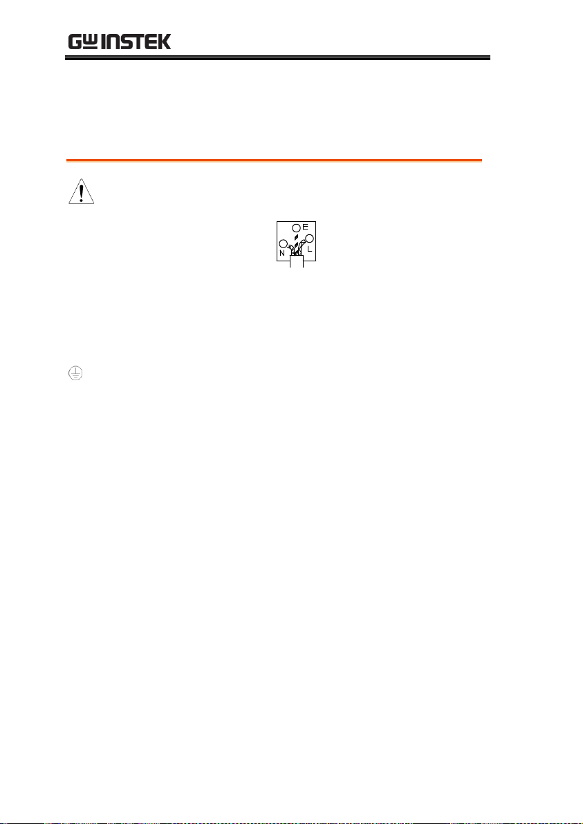
Green/ Yellow:
Earth Blue:
Neutral
Brown:
Live (Phase)
Power cord for the United Kingdom
When using the power supply in the United Kingdom, make sure
the power cord meets the following safety instructions.
NOTE: This lead/appliance must only be wired by competent persons
WARNING: THIS APPLIANCE MUST BE EARTHED
IMPORTANT: The wires in this lead are coloured in accordance with the following code:
As the colours of the wires in main leads may not correspond with
the coloured marking identified in your plug/appliance, proceed
as follows:
The wire which is coloured Green & Yellow must be connected to
the Earth terminal marked with either the letter E, the earth symbol
or coloured Green/Green & Yellow.
The wire which is coloured Blue must be connected to the terminal
which is marked with the letter N or coloured Blue or Black.
The wire which is coloured Brown must be connected to the
terminal marked with the letter L or P or coloured Brown or Red.
If in doubt, consult the instructions provided with the equipment
or contact the supplier.
This cable/appliance should be protected by a suitably rated and
approved HBC mains fuse: refer to the rating information on the
equipment and/or user instructions for details. As a guide, a cable
of 0.75mm2 should be protected by a 3A or 5A fuse. Larger
conductors would normally require 13A types, depending on the
connection method used.
Any exposed wiring from a cable, plug or connection that is
engaged in a live socket is extremely hazardous. If a cable or plug is
deemed hazardous, turn off the mains power and remove the cable,
any fuses and fuse assemblies. All hazardous wiring must be
immediately destroyed and replaced in accordance to the above
standard.
8

PLR SERIES
Model name
Rated Voltage
Rated Current
Rated Power
PLR 20-18
20V
18A
360W
PLR 36-10
36V
10A
360W
PLR 60-6
60V
6A
360W
PLR 20-36
20V
36A
720W
PLR 36-20
36V
20A
720W
PLR 60-12
60V
12A
720W
Standard Interface unit for the PLR series.
PLR-RS
RS-232C Interface.
Optional Interface units for the PLR series.
PLR-GU
GPIB/USB Interface
PLR-LU
LAN/USB Interface
PLR-ARC
Analog Remote Control Interface
PLR SERIES
About this Manual
This manual applies to the following PLR series power supply
units and optional interface units.
9

PLR Series User Manual
Low ripple and low noise
The PLR power supply units reduce output ripple and output
noise with a series transistor for output voltage.
Select the setting digits for voltage and current
The output voltage and current are indicated by 4 digits. You can
select a digit to set the voltage and the current. The PLR power
supply unit is also equipped with a fine adjustment function for
instances in which more precise setting capabilities are required.
Preset function
The unit has 3 preset memory points in which different voltage
and current settings can be stored. This function enables you to
Outline of Product
The PLR series are small, lightweight, switching type and dropper
type, regulated DC power supply units with low noise. Because
the PLR series power supply units are highly reliable and have a
variety of protective functions, they are ideally suited for industrial
use, such as for performing reliability tests, durability tests, and
age-testing electronic components.
The PLR series offer a variety of functions for a variety of
applications: preset functions (3 setting points); protective functions
against output overvoltage, under voltage and overcurrent; output
discharge circuit/cancel function; output off timer function; CC
priority mode while the output is on; sequence function; and
operation by external analog signal.
There are 3 types of optional interface boards, PLR-GU, PLR-LU
and PLR-ARC. These boards replace the standard board equipped
with the unit (PLR-RS), and provide communication functions.
Features
PLR Power Supply Unit
10

PLR SERIES
easily change the voltage and current settings.
Output off timer function
To prevent battery overcharge and similar problems, this
function automatically turns the output off after a preset amount
of time has passed while the output is on.
CC priority mode
Compared to general switching power supply units, the PLR
power supply unit is better able to reduce current overshoot,
thanks to our original current-overshoot inhibit circuit. This
circuit produces a load that enables the unit to operate at a
constant current while the output is on.
Sequence function
Sequence programs can be written to the unit from a computer
via the interface boards (PLR-RS, PLR-GU and PLR-LU).
Sequence programs can be executed by performing panel or
computer operations. You can also perform sequence operations
with a maximum of 1000 steps by using a program written by the
computer. The minimum step unit is 50ms.
Remote sensing function
This function uses the remote sensing terminal to compensate for
voltage drop caused by the wires.
Protective functions
The PLR power supply unit has protective functions against
overvoltage, under voltage and overcurrent for the primary side,
and overvoltage, overcurrent, remote sensing (terminal open),
and internal heat for the secondary side. The unit is also
equipped with OVP (over-voltage protection), UVP (undervoltage protection), and OCP (over-current protection) for the
load. The setting values for these protective functions are
changeable.
Master-slave operation
The PLR power supply unit can perform master-slave operation.
Master-slave operation can be performed with a maximum of 3
units (of the same voltage model) connected in parallel, and with
11

PLR Series User Manual
a maximum of 2 units (of the same model) connected in series.
External analog signal operation
When setting the voltage and current by external voltage and
resistance, the setting values set externally will be superimposed
on the setting values set on the panel. The external setting values
can be adjusted on the panel. The output can be turned on and off
by an external contact switch.
Dispersion circuit for rush current prevention
The PLR power supply unit is able to restrain and minimize the
primary side current and voltage distortions caused by rush
current on the primary side at the time the unit is switched on,
thanks to the main relay’s on/off operation and our original
dispersion circuit for rush current prevention.
Power factor correction circuit, as well as voltage and current
range for worldwide use
The PLR power supply unit is equipped with a power factor
correction circuit that has a rated output of approximately 0.99. It
is operable with supply voltages ranging from 100VAC to
240VAC, without changing the settings.
CE Marked
The PLR power supply unit conforms to CE marking (under
voltage directive, EMC directive). It also complies with the
regulations for the harmonic current of power supply units.
Units equipped with the PLR-RS can be connected to a computer
and controlled by RS-232C. PLR-RS can also control 31 PLR
power supply units via a local bus connection.
PLR-RS
12

PLR SERIES
PLR-GU is connected to a computer through a GP-IB or USB.
Fourteen units may be connected with a computer through GPIB, or 32 units may be connected through USB.
Units connected to the computer can be connected with 31 PLR
power supply units via a local bus connection.
PLR-LU is connected to a computer through a LAN or USB. 32
units may be connected through USB.
Units connected to the computer can be connected with 31 PLR
power supply units via a local bus connection.
Cable for parallel master-slave
PLR-001 : Connectable with three PLR power supply units.
Cable for in-series master-slave
PLR-002 : Connectable with two PLR power supply units.
CAUTION
When connecting cables, make sure to connect
the correct cables.
Connecting the wrong cables may cause product
failure.
PLR-GU (option)
PLR-LU (option)
Cable for master-slave operation (option)
13
PLR Series User Manual
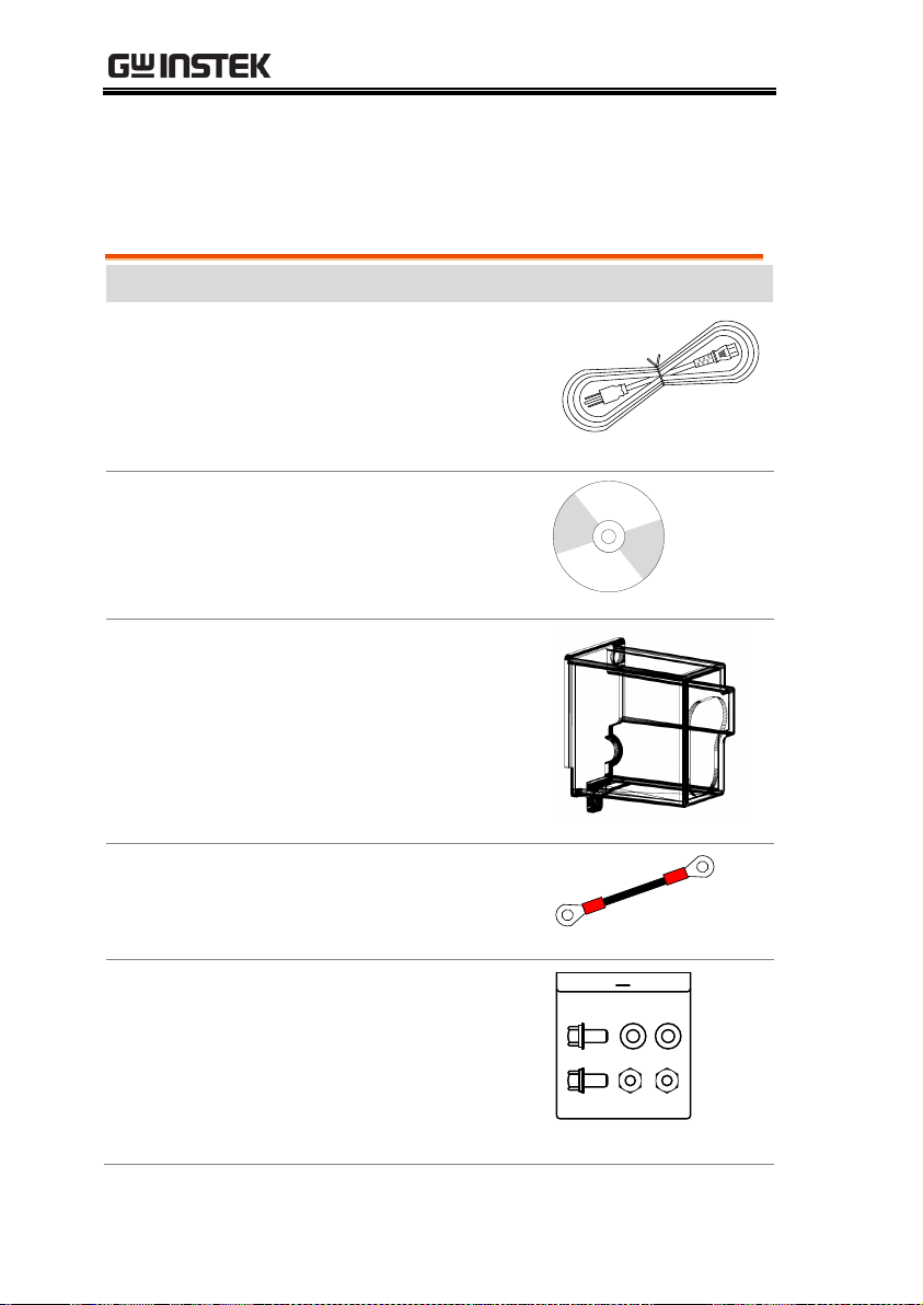
Item
Description
1
Power cable: 14AWG, 15A, 2M
Power cable: 1 pc
2
CD-ROM: User Manual
1 pc
3
Rear output terminal cover
See page 19 for details.
1 pc
4
Output grounding cable
See page 17 for details.
1 pc
5
Bolt set
Contents:
Hexagon head bolt (P-3): 2 pcs
Flat washer: 2 pcs
Hexagon nut: 2 pcs
See page 16 Connect to the
Output Terminals for details.
1 pkt
Prior to Use
Standard Accessories
14

PLR SERIES
6
M3 Small screw washer: 1 set
(For attaching the grounding
cable to one of the rear output
terminals.)
See page 17 for details.
7
M3 Large screw washer: 2 sets
(For attaching the rear output
terminal cover.)
See page 19 for details.
8
M4 Small screw washer: 1 set
(For Connecting the protective
grounding terminal on the
bottom face)
See page 22 for details.
9
PLR-RS: RS-232C Interface
Card (Attached to power
supply)
Part number
Description
PLR-ARC
Analog Remote Control Interface Card
PLR-GU
GPIB/USB Interface Card
PLR-LU
LAN/USB Interface Card
PLR-001
Parallel Connection Signal Cable (2 to 3 units)
PLR-002
Series Connection Signal Cable
GRJ-1101
Modular Cable (0.5m)
GRJ-1102
Modular Cable (1.5m)
GRA-427
Rack mount adapter
Optional Accessories
15

PLR Series User Manual
The power cable should be connected to an AC inlet or an input
terminal block.
Warning
Make sure to properly connect the power cable.
Failure to do so may result in electric shock or fire.
Using the unit without the AC input terminal cover
may result in electric shock or fire.
Perform this operation before connecting the power cable to an AC
outlet or the distribution panel.
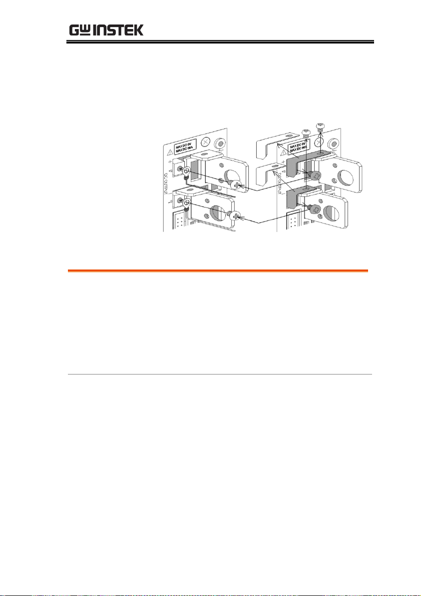
Use the supplied bolt set to connect the load cable to the rear output
terminals. Adjust the tightening torque of each bolt to 25 kgf/cm.
Check the connection between the load and the output terminals of
the unit. Make sure that the polarity is not inverted, and that no
short circuits have occurred.
Steps
1. Attach a round crimp-style terminal (inner
diameter of at least 6.4 mm) to the load cable.
2. Insert the bolt into the hole from left side of the
output terminal.
3. From the right side of the output terminal, first
attach the load cable (with the round crimpstyle terminal attached), followed by the
washer and then the nut. Finally, secure the
bolt.
Connect the Power Cable
Connect to the Output Terminals
16
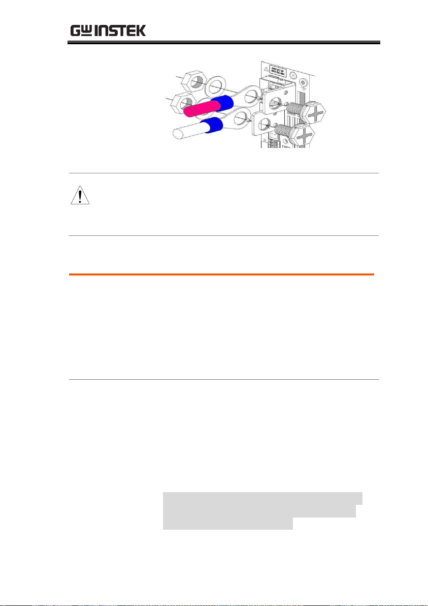
PLR SERIES
Fig. 2-2 Connecting the load cable to the rear
output terminals
Warning
Make sure the voltage of the unit’s output
terminals has sufficiently fallen before touching
and operating the load or output terminals.
Failure to do so may result in electric shock.
(You do not need to perform this operation if the output is not to be
grounded.)
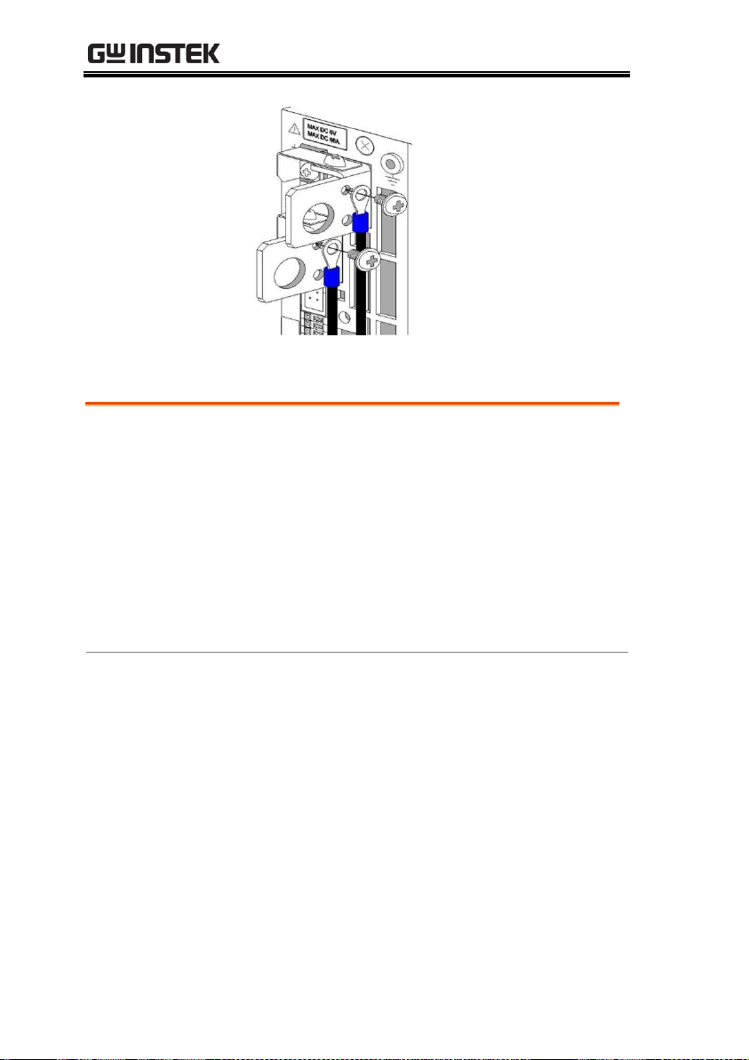
Use the M3 Small screw w/washer to attach the grounding cable to
one of the rear output terminals.
Tightening torque of screw: 5kgf/cm.
Steps
1. From the left side of the rear output terminals,
attach the grounding cable to the M3 hole of
one of the output terminals.
2. Attach the grounding cable to either the
positive output terminal or the negative output
terminal. Do not attach the cable to both.
3. If you attach the grounding cable to both the
positive and negative output terminals, the
unit output will short circuit.
Attaching the Output Grounding Cable
17
PLR Series User Manual
You only need to perform this operation if you plan to use the
voltage remote sensing function of the unit.
Use the removed M3 screws to attach the voltage remote sensing
cables to the voltage remote sensing terminals.
Tightening torque of screw: 5kgf/cm
Carefully store the positive and negative shorting bars and the two
M3 screws that were removed.
Steps
1. Remove the M3 screws (4 screws) from the
positive and negative rear output terminals
and the positive and negative voltage remote
sensing terminals, and then remove the
positive and negative shorting bars.
2. Attach the positive and negative voltage
remote sensing cables to the positive and
negative voltage remote sensing terminals.
Connecting the voltage remote sensing cables
18
PLR SERIES
3. Attach a round crimp-style terminal (inner
diameter of at least 3.2mm, with the smallest
possible outer diameter) to the voltage remote
sensing cables.
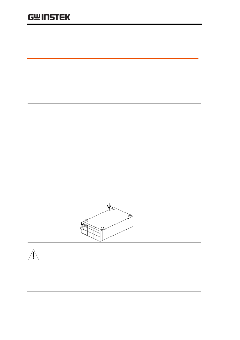
The rear output terminal cover should always be attached even
when rear output terminals of the unit are not in use.
Use the M3 Large screw with washer to attach the rear output
terminal cover.
Tightening torque of screw: 5kgf/cm.
Steps
1. Run the load cable and the voltage remote
sensing cable through the output terminal
cover, and then fix the output terminal cover to
the unit, using the two large screws with
washers.
2. Fix the output grounding cable to the output
grounding terminal, together with the output
terminal cover.
Attaching the rear output terminal cover
19

PLR Series User Manual
Output
grounding
cable
20

PLR SERIES
To maintain an output voltage of approximately 0 V when the
output is off, the unit is equipped with a discharge circuit for
removing the electric charge from the output capacitor.
When the output is off, it takes approximately 1 second for the
discharge circuit to remove the electric charge from the output
capacitor when the capacitor is fully charged to its rated voltage.
If a capacitive load, such as a battery or capacitor, is connected to
the unit and used, it takes longer to lower the output voltage when
the output is off. If the output is turned off while a capacitive load
is connected, be sure to use a voltmeter to confirm that the voltage
has sufficiently fallen before touching the output terminal or the
load.
The discharge circuit for the output capacitor does not work if the
unit’s output HI-R function is used.
Compared to when the output HI-R function is not used, it takes
longer for voltage to fall when a capacitive load is used.
Caution on Connecting to a Capacitive Load
21
PLR Series User Manual
There is a protective grounding terminal on the bottom face of this
unit.
To ensure the safe use of this product, follow the procedure below
to connect the protective grounding terminal.
Steps
1. Attach the wire (recommended by the
manufacturer) for round crimp-style terminals
V1.25-M4 (JST) or equivalent.
2. Attach the round crimp-style terminal to the
cable.
3. Attach the cable with round crimp-style
terminal to the protective grounding terminal
on the bottom face of the unit, using the
accessory M4 screw for the grounding
connection to secure the cable.
Warning
Make sure to properly connect the protective
grounding terminal on the bottom face. Failure to
do so may result in electric shock. If you do not
connect the protective grounding terminal on the
bottom face, it will not conform to the CE
conformity.
Connecting the protective grounding terminal on the bottom face
22

PLR SERIES
When mounting the unit in a rack, use one of the following
attachments:
Rack mount adapter GRA-427 (for JIS rack)
GRA-427 (for EIA rack)
When mounting the unit in a rack, replace the screws on the left and
right sides of the unit (two on each side) with the flat countersunk
head screws.
When mounting the unit in a rack, remove the screw for the
protective grounding terminal on the bottom face of the unit. For
your own safety, make sure to securely connect the rack to the
ground before using the unit.
Caution on mounting the unit in a rack
23

PLR Series User Manual
Be sure to turn off the power switch before connecting the power
cable to the AC outlet or distribution panel.
Be sure to plug the supplied power cable into an AC outlet with
earth ground.
Warning
Plugging the power cable into an outlet or
distribution panel that is not properly grounded
may result in electric shock or fire. Be sure to ask
a qualified engineer to connect the power cable to
the distribution panel.
If the unit is used in a hot place and the internal temperature of
the unit rises, the built-in overheat protection circuit activates
and turns off the output. Do not use the unit in a location where
the grill in the front panel or air outlet port in the rear panel is
blocked. Blocking these ports will cause the internal temperature
to rise. Maintain sufficient distance between these ports and
objects. In some conditions, hot air may blow out of the air outlet
port in the rear panel. Be careful.
Do not use the PLR power supply unit in a place with a lot of
dust or corrosive gas. These substances can cause the product to
deteriorate.
Do not use the unit on an incline or a place subject to vibration.
Doing so can cause the unit to fall off the rack or fall over, which
may result in damage to the unit or personal injury.
Connecting the Power Cable to the Primary Power
Installation Environment
24
PANELS
2
5
1
4
3
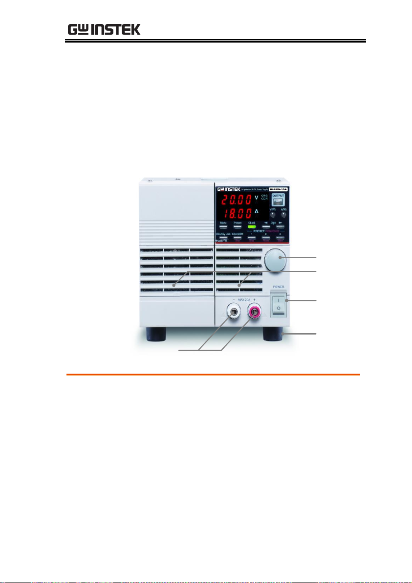
1. Power switch
Turns the AC power on (I) and off (O).
Do not position the power supply in such a way
as to make accessing/operating the power
switch difficult.
2. Front output terminals
Front output terminals with a current limit of
20A. Use the unit within the current limit
PANELS
Front Panel
Front Panel (The above figure shows the front panel of the PLR 20-18)
25

PLR Series User Manual
3. Rotary encoder
Changes the set voltage and current, and is
used to set functions.
4. Grill
Air intake port.
Push up the mark in the bottom center of the
grill to detach the cover when cleaning or
replacing the dust filter inside.
5. Rubber shoes
Detachable.
If the unit is mounted in a rack and the shoes
are not needed, they may be removed.
26
PANELS
6
7
13
12
14
21
17 18 19 20
8
9
11
10
15
16
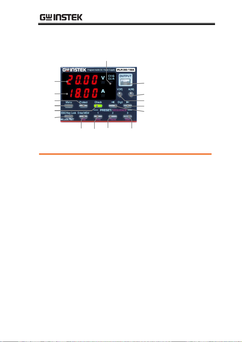
6. Voltage indicator (red LEDs): 4-digit display, unit indication
Indicates the set voltage, output voltage, output
power, and MENU items.
“W” is lit in red when the indicator displays the
output power.
7. Current indicator (red LEDs): 4-digit display, unit indication
Indicates the set current, output current, output
power, and MENU items.
“W” is lit in red when the indicator displays the
output power.
8. CV/CC LED (green/red)
When the output is on, the LED is lit in green
when CV is in operation and red when CC is in
operation.
Turns off when output is off. It blinks red
when the CC priority mode is selected.
Operation Panel
Operation Panel (The above figure shows the operation panel of the PLR
20-18)
27

PLR Series User Manual
9. OUTPUT key (red/amber)
Manual operation:
Lit in red when the output is on.
Alternately blinks red and amber when the
output off timer is set and the output is on.
Pressing this key turns the output on and off.
It is not possible to turn the output on and off
when the MENU key is lit in green.
Sequence operation:
If this key is pressed while a sequence
manual/automatic operation is being executed,
the output will turn off and the sequence will
be interrupted.
10. V key (green/amber)
The voltage is set by operating this front panel
key:
Pressing this key causes it to turn off or light in
green.
When this key is lit in green, it is possible to
change the blinking digit of the set voltage in
the voltage indicator.
Pressing and holding down this key switches
the voltage display to the power display.
Pressing and holding down this key again
switches the display back to the voltage
display.
The key is lit in amber when the voltage is set
by external analog signals.
28
 Loading...