

Page 1

Electrical Safety Tester
GPT-9600 Series
QUICK START GUIDE
GW INSTEK PART NO. 82PT-96030MA1
ISO-9001 CERTIFIED MANUFACTURER
Page 2

This manual contains proprietary information, which is protected by
copyright. All rights are reserved. No part of this manual may be
photocopied, reproduced or translated to another language without
prior written consent of Good Will company.
The information in this manual was correct at the time of printing.
However, Good Will continues to improve products and reserves the
right to change specification, equipment, and maintenance
procedures at any time without notice.
Good Will Instrument Co., Ltd.
No. 7-1, Jhongsing Rd., Tucheng Dist., New Taipei City 236, Taiwan.
Page 3

Table of Contents
Table of Contents
SAFETY INSTRUCTIONS ................................................... 4
Safety Symbols ............................................................................................. 4
Safety Guidelines ......................................................................................... 5
Power cord for the United Kingdom ........................................................... 7
INTRODUCTION ............................................................... 8
GPT-9600 Series Overview .......................................................................... 8
Main Features .............................................................................................. 9
Accessories .................................................................................................. 9
Panel Overview .......................................................................................... 11
Front Panel ................................................................................................. 11
OPERATION .................................................................... 12
Status Modes ............................................................................................. 12
Operation Flow Chart ................................................................................ 12
READY Status ............................................................................................ 13
EDIT Status ................................................................................................ 14
TEST Status ................................................................................................ 16
PASS/FAIL Result ...................................................................................... 17
STOP Status ............................................................................................... 18
Common Utility Settings ........................................................................... 19
TEST Utility Settings .................................................................................. 20
3
Page 4

GPT-9600 Series Quick Start Guide
WARNING
Warning: Identifies conditions or practices that
could result in injury or loss of life.
CAUTION
Caution: Identifies conditions or practices that
could result in damage to the instrument or to
other properties.
DANGER High Voltage
Attention Refer to the Manual
Protective Conductor Terminal
Frame or Chassis Terminal
Earth (ground) Terminal
SAFETY INSTRUCTIONS
This chapter contains important safety
instructions that you must follow during
operation and storage. Read the following before
any operation to ensure your safety and to keep
the instrument in the best possible condition.
Safety Symbols
These safety symbols may appear in this manual or on the
instrument.
4
Page 5
SAFETY INSTRUCTIONS
Do not dispose electronic equipment as unsorted
municipal waste. Please use a separate collection
facility or contact the supplier from which this
instrument was purchased.
General
Guideline
CAUTION
Do not place any heavy object on the
instrument.
Avoid severe impact or rough handling that
leads to damaging the instrument.
Do not discharge static electricity to the
instrument.
Use only mating connectors, not bare wires, for
the terminals.
Do not block the cooling fan opening.
Do not disassemble the instrument unless you
are qualified.
(Measurement categories) EN 61010-1:2010 specifies the
measurement categories and their requirements as follows. The
GPT-9600 Series does not fall under category II, III or IV.
Measurement category IV is for measurement performed at the
source of low-voltage installation.
Measurement category III is for measurement performed in the
building installation.
Measurement category II is for measurement performed on the
circuits directly connected to the low voltage installation.
Power Supply
WARNING
AC Input voltage range:
100-120/220-240VAC ±10%
Frequency: 50Hz/60Hz
To avoid electrical shock connect the protective
grounding conductor of the AC power cord to
an earth ground.
Connect the Earth terminal on rear panel to an
earth ground.
Safety Guidelines
5
Page 6

GPT-9600 Series Quick Start Guide
Cleaning the
GPT-9600
Disconnect the power cord before cleaning.
Use a soft cloth dampened in a solution of mild
detergent and water. Do not spray any liquid.
Do not use chemicals containing harsh material
such as benzene, toluene, xylene, and acetone.
Operation
Environment
Location: Indoor, no direct sunlight, dust free,
almost non-conductive pollution (Note below)
Relative Humidity: ≤ 70% (no condensation)
Altitude: < 2000m
Temperature: 0˚C~40˚C
(Pollution Degree) EN 61010-1:2010 specifies the pollution degrees
and their requirements as follows. The GPT-9600 Series falls under
degree 2.
Pollution refers to “addition of foreign matter, solid, liquid, or
gaseous (ionized gases), that may produce a reduction of dielectric
strength or surface resistivity”.
Pollution degree 1: No pollution or only dry, non-conductive
pollution occurs. The pollution has no influence.
Pollution degree 2: Normally only non-conductive pollution
occurs. Occasionally, however, a temporary conductivity caused
by condensation must be expected.
Pollution degree 3: Conductive pollution occurs, or dry, non-
conductive pollution occurs which becomes conductive due to
condensation which is expected. In such conditions, equipment
is normally protected against exposure to direct sunlight,
precipitation, and full wind pressure, but neither temperature
nor humidity is controlled.
Storage
environment
Location: Indoor
Temperature: -10°C to 70°C
Relative Humidity: ≤ 85% (no condensation)
6
Page 7

SAFETY INSTRUCTIONS
Green/ Yellow:
Earth
Blue:
Neutral
Brown:
Live (Phase)
Power cord for the United Kingdom
When using the safety tester in the United Kingdom, make sure the
power cord meets the following safety instructions.
NOTE: This lead/appliance must only be wired by competent persons
WARNING: THIS APPLIANCE MUST BE EARTHED
IMPORTANT: The wires in this lead are coloured in accordance with the
following code:
As the colours of the wires in main leads may not correspond with
the coloured marking identified in your plug/appliance, proceed
as follows:
The wire which is coloured Green & Yellow must be connected to
the Earth terminal marked with either the letter E, the earth symbol
or coloured Green/Green & Yellow.
The wire which is coloured Blue must be connected to the terminal
which is marked with the letter N or coloured Blue or Black.
The wire which is coloured Brown must be connected to the
terminal marked with the letter L or P or coloured Brown or Red.
If in doubt, consult the instructions provided with the equipment
or contact the supplier.
This cable/appliance should be protected by a suitably rated and
approved HBC mains fuse: refer to the rating information on the
equipment and/or user instructions for details. As a guide, a cable
of 0.75mm2 should be protected by a 3A or 5A fuse. Larger
conductors would normally require 13A types, depending on the
connection method used.
Any exposed wiring from a cable, plug or connection that is
engaged in a live socket is extremely hazardous. If a cable or plug is
deemed hazardous, turn off the mains power and remove the cable,
any fuses and fuse assemblies. All hazardous wiring must be
immediately destroyed and replaced in accordance to the above
standard.
7
Page 8

GPT-9600 Series Quick Start Guide
INTRODUCTION
This Quick Start Guide is intended as a fast introduction to
operating the GPT-9600 Series Safety Testers. This Quick Start
Guide assumes that the user is familiar with safety testers.
For comprehensive instructions on the GPT-9600 Series, please see
the User Manual, located on the accompanying CD.
GPT-9600 Series Overview
The GPT-9600 Series Safety Testers are AC/DC withstanding
voltage and insulation resistance safety testers. The GPT-9603 is an
AC/DC withstanding and insulation resistance safety tester. The
GPT-9602 is an AC/DC withstanding safety tester. The GPT-9612 is
an AC withstanding and insulation resistance safety tester, while
the GPT-9601 is purely an ACW tester.
Note: Throughout this quick start guide, the terms ACW, DCW and
IR refer to AC Withstanding, DC Withstanding and Insulation
Resistance, respectively. GPT-9600 refers to any of the GPT-96XX
models.
8
Page 9

Main Features
Performance
ACW: 5kVAC
DCW: 6kVDC
IR: 50V, 100V, 250V, 500V, 1000V
Features
Timer control
Safety discharge
Over temperature, voltage and current
protection
Pass, Fail, Test, High Voltage and Ready
indicators
PWM output (increased reliability)
Interlock (configurable)
Interface
Remote control start/stop interface terminal
Signal I/O port for pass/fail/test monitoring
and start/stop control/interlock
Standard Accessories
Part number
Description
N/A
GPT-96XX unit.
N/A
User manual CD
N/A
Quick start guide
GHT-114 x1
Test lead
Region dependent
Power cord
N/A
Remote terminal male plug
N/A
Interlock key
N/A
CTC (Calibration Traceable
Certificate)
INTRODUCTION
Accessories
9
Page 10

GPT-9600 Series Quick Start Guide
Optional Accessories
Part number
Description
GHT-205
High Voltage Test Probe
GHT-113
High Voltage Test Pistol
GRA-417
Rack mount kit
10
Page 11

INTRODUCTION
PASS/FAIL indicators
Navigation keysFunction keys
HIGH VOLTAGE
indicator
RETURN
terminal
REMOTE terminal
STOP button
START button
POWER
button
Display
Scroll wheel
Configuration keys
READY indicator
TEST indicator
HIGH VOLTAGE
output terminal
AC / DC Withstanding Voltage /
Insulation Resistance
Tester
GPT-9603
POWER
START STOP
REMOTE
ESC FIELD
PASS FAIL READY TEST
HIGH VOLTAGE
CAUTION
5.0 kVAC MAX.
6.0 kVDC MAX.
RETURN
EDIT SAVE UTILITY
Fan
Fuse holderLine voltage
SIGNAL I/O
GND
TO AVOID ELECTRIC SHOCK THE POWER CORD
PROTECTIVE GROUNDING CONDUCTOR MUST BE
ONLY WITH SPECIFIED TYPE AND RATED FUSE.
NO OPERATOR SERVICEABLE COMPONENTS INSIDE.
DO NOT REMOVE COVERS. REFER SERVICING TO
FOR CONTINUED FIRE PROTECTION. REPLACE
CONNECTED TO GROUND.
QUALIFIED PERSONNEL.
WARNING
SER. NO. LB
SIGNAL I / O
CALIBRATION
USE ONLY
REMOVED FROM THE INSTRUMENT
BEFORE REPLACING THE FUSE
AC
MAX.
400VA
POWER
ENSURE THE POWER IS
LINE VOLTAGE
100 120V
( 50 / 60Hz )
250V
T 4A
FUSE
220 240V
GND
Calibration port
Panel Overview
Front Panel
Rear Panel
11
Page 12

GPT-9600 Series Quick Start Guide
status
SET
T
status
OTS
P
status
YAER
D
status
1
IDE
T
Press
START
Press
SAVE
Press
EDIT
Press
STOP
Press
STOP
TEST UTILITY
Settings
1
Press
UTILTY
1. Press ESC to cancel and return to the previous screen.
status
SAP
S
Status (buzzer on)
IAF
L
PASS/FAIL
Judgement
Common Utility
Settings
1
Press
UTILITY
Press
SAVE
Press
SAVE
Status (buzzer off)
IAF
L
Press
STOP
Press
STOP
Press
STOP
Press
START
OPERATION
Status Modes
This section describes the overall structure of the operating modes
for the GPT-9600 Series safety testers. The testers have 6 status
modes: (EDIT, READY, TEST, STOP, FAIL, PASS). The flow chart
below describes how to navigate from mode to mode.
Operation Flow Chart
12
Page 13

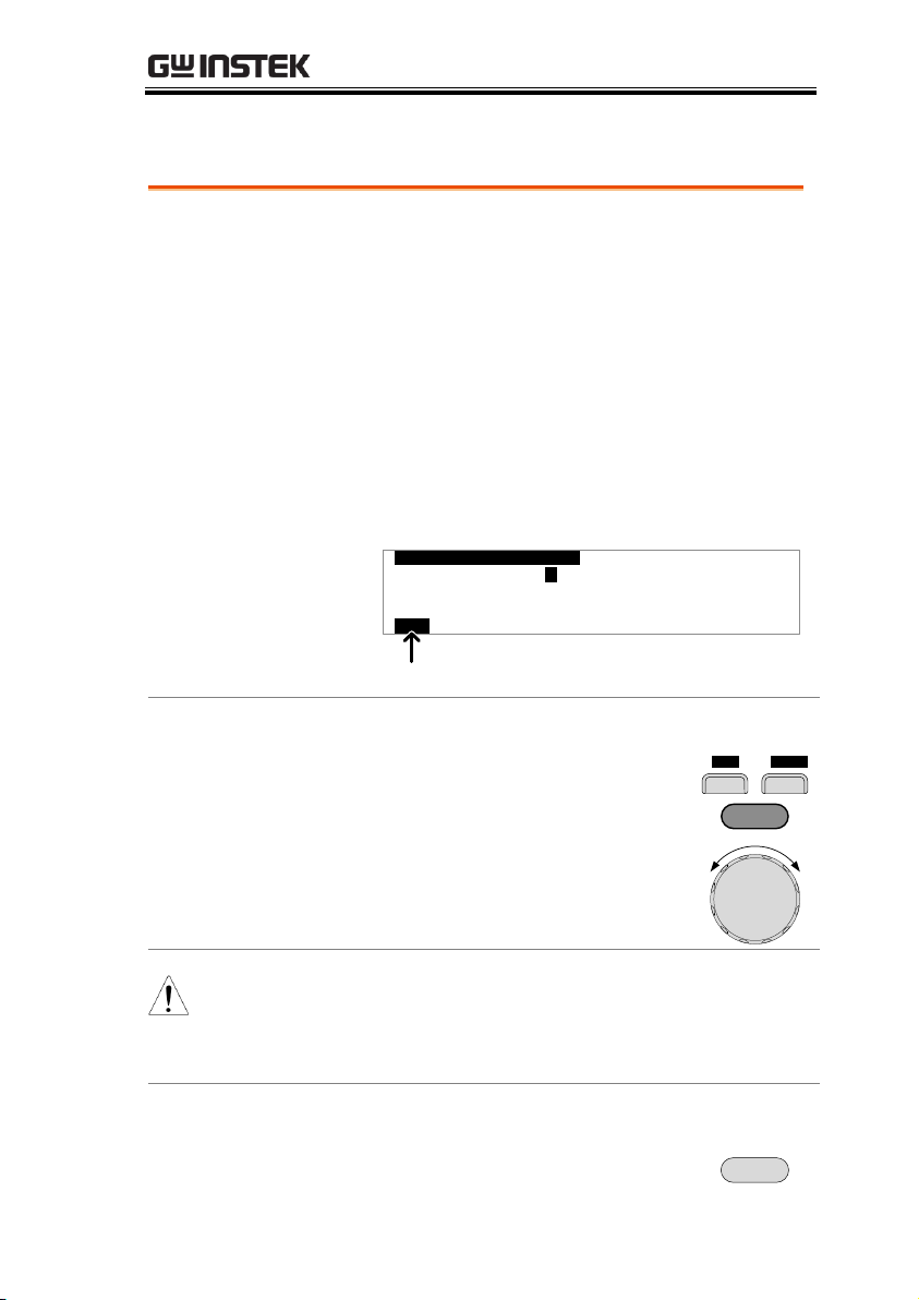
READY Status
Description
When the tester is in READY status, it is ready
to begin testing. Pressing the START button
will begin testing and put the tester into TEST
status. Pressing the EDIT key will put the tester
into the EDIT status. Pressing the UTILIY key
will enter the Common Utility settings.
The READY status can also be used to set the
testing mode. The testing mode can be set to
run a single test at a time or to run two different
tests sequentially.
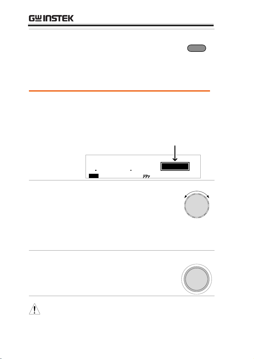
H = 2 2 . 0 m A
m AL 0= 0 0. 7 4 S = 1T
CWDA CW R I DO EM T M EI
READY Status
Test mode
1 00
k V
AER
D Y
Am
Set the Testing Mode
Press the MODE soft-key to toggle between MODE
(single test) and each of the Auto Modes. (AC-IR,
IR-AC, DC-IR, IR-DC)
The Auto Mode function sets two different test
functions and the order that will they run. I.e., AC-IR
means an ACW test is performed followed by an IR
test.
When the unit is in TEST status, the Test Mode
determines whether a single test is run or if two tests
are run sequentially.
O D EM
OPERATION
13
Page 14

GPT-9600 Series Quick Start Guide
Go to EDIT Status
Press the EDIT key.
EDIT
Set the Test Voltage
When in the READY mode, turn the scroll wheel
knob to set the test voltage.
Start Testing
Press the START button to begin testing.
The tester will go into TEST status.
START
WARNING
If Double Action is active, the START button must
be pressed within 500ms after the STOP button
was pressed to be able to start testing.
WARNING
If INTERLOCK is set to ON and the interlock key is
not connected to the SIGNAL I/O port,
INTERLOCK OPEN will be displayed on the screen,
preventing the test from starting. See page 19 for
the Common Utility settings.
Description
EDIT status is used to edit the test parameters
(excluding the test voltage). Pressing the SAVE
key will save any changes and return to the
READY status. Pressing the ESC key will cancel
any changes and return to the READY status.
Pressing the UTILITY key will enter the TEST
Utility settings.
EDIT Status
14
Page 15

OPERATION
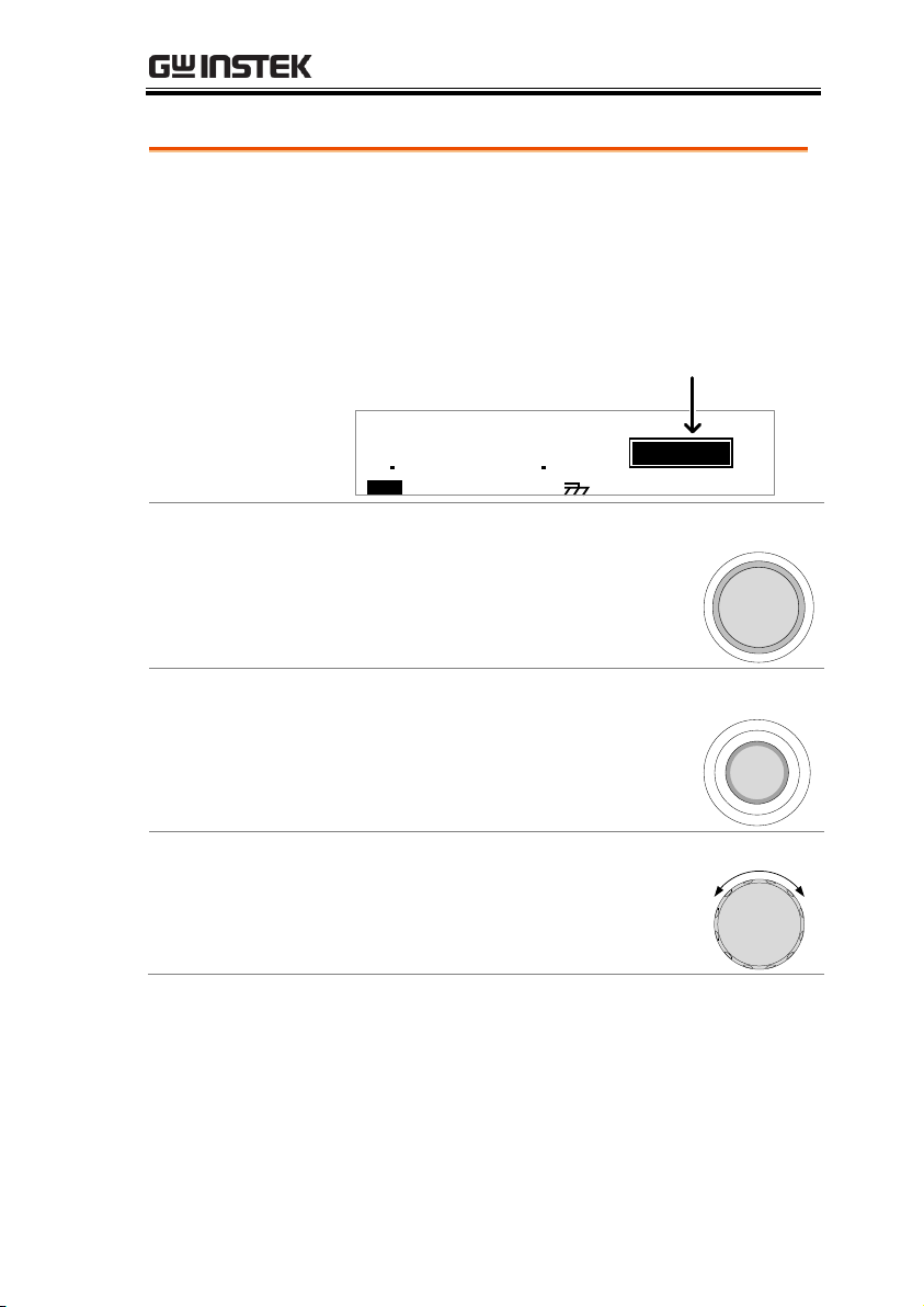
H = 2 2 . 0 m A
m AL 0= 0 0. 7 4 S = 1T
CWDA CW R I DO EM T M EI
Time setting
ACW, DCW and IR
test indicators
Ground mode
Time soft-key
High limit Low limit EDIT Status
0 00
k V
IDE
T
Am
Choose Test Function
Use the ACW, DCW or IR soft-keys to choose a
test function.
A CW D CW I R
Choose High/Low limits
Use the FIELD key to bring the cursor to the H or L
setting.
Use the scroll wheel to edit the setting.
FIELD
Test Time
Use the FIELD key to select the T setting.
Use the scroll wheel to edit the time.
Press the TIME soft-key to toggle the test time
ON/OFF. Note that the test time cannot be edited
with the scroll wheel when the test time is set to OFF.
FIELD
I M ET
Save the test settings and return to READY Status
Press the SAVE key. The current test is saved in
memory.
The tester reverts back to READY status.
SAVE
15
Page 16
Exit EDIT status and Return to READY Status
Press the ESC key.
The tester does not save and returns back to READY
status.
ESC
TEST Status
Description
TEST status is active when a test is running.
Pressing STOP will cancel the test and put the
tester into the STOP status. Waiting for the test
to complete will result in a PASS or FAIL
judgment.
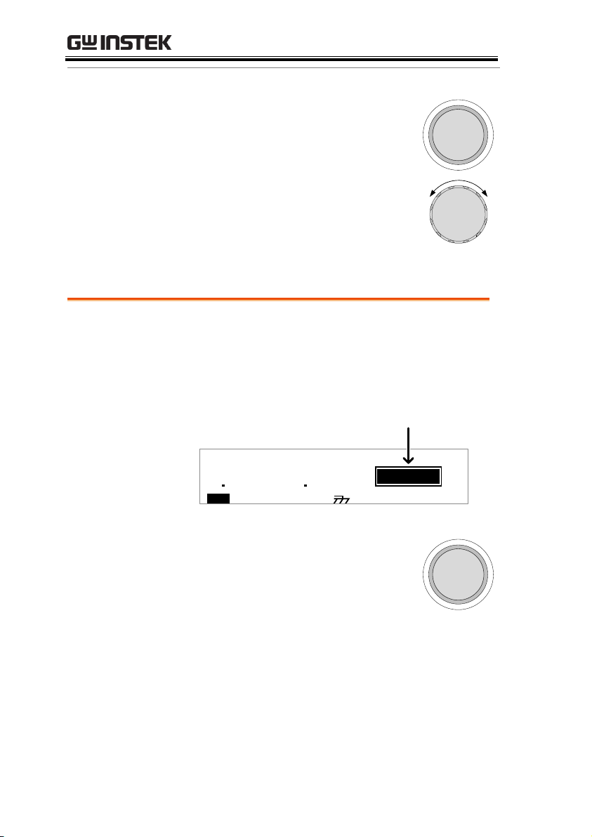
H = 2 2 . 0 m A
m AL 0= 0 0. 0 8 S = 0T
CWDA CW R I DO EM T M EI
TEST Status
0 14
k V
SET
T
Am
0 00
Set the Test Voltage
For ACW and DCW mode, the scroll wheel can be
used to set the test voltage when the test is running.
Clockwise increases the voltage.
Anti-clockwise reduces the voltage.
Get Test Results
Wait for the test to finish.
Abort Test
Press the STOP button
The tester will go into STOP status.
STOP
NOTE
When in STOP status all panel keys are locked
except for the STOP key.
GPT-9600 Series Quick Start Guide
16
Page 17
OPERATION
Results
When the tester is allowed to run to
completion, the test result is shown as a PASS
or FAIL. When the PASS or FAIL results are
shown on the screen, the PASS or FAIL
indicators will also light up.
Results
H = 2 2 . 0 m A
m AL 0= 0 0. 6 0 S = 0T
CWDA C W R I DO EM T M EI
FAIL Status
1 00
k V
IAF
L
Am
23 0
Return to READY Status
Press the STOP button once for a PASS judgment, or
twice for a FAIL judgment.
STOP
Restart the Test
After a PASS judgment, the test can be re-run by
pressing the START button.
START
View PASS Auto Mode Test Results
For a PASS result, turn the scroll wheel left or right to
view test results. Press the STOP button to return to
READY status.
PASS/FAIL Result
17
Page 18
View FAIL Auto Mode Test Results
For a Fail Judgment, press the STOP button once to turn
off the buzzer tone. Then turn the scroll wheel left or
right to view test results. Pressing the STOP button again
will return the tester to READY status.
STOP
STOP Status
Description
STOP status is shown when a test does not
finish running and has been stopped by the
operator. When in STOP status, pressing STOP
will return the tester to READY status.
H = 2 2 . 0 m A
m AL 0= 0 0. 0 8 S = 0T
CWDA C W R I DO EM T M EI
STOP Status
0 14
k V
OTS
P
Am
0 00
Return to READY Status
Press the STOP button
STOP
GPT-9600 Series Quick Start Guide
18
Page 19
OPERATION
Description
The Common Utility menu is accessed by
pressing the UTILITY key when the tester is in
READY status. This utility controls the LCD
and control settings. These settings are system
wide.
The Common Utility settings include:
LCD: LCD Contrast, LCD Brightness
CTRL: Start Ctrl (FRONT PANEL, SIGNAL
I/O, REMOTE CONNECT), Double
Action, Key Lock, Interlock
C OM MO N U
T LI T YI
L C D B r i g h t n e s : B Rs I
L C D C o n t r a s t : 7
= 0 0R
MT I E = 0 0RG H T
MT I E = 0 0R
L C D C T R L MT I E = 0 0R
Utility selection
Select a Utility Setting.
Choose a utility by pressing the LCD or CTRL soft-
key under the LCD bezel.
The chosen utility will be displayed.
Use the FIELD key to highlight a setting.
Use the scroll wheel to choose or edit a parameter for
the setting.
L C D
C T R L
FIELD
NOTE
The INTERLOCK function is set to OFF by default
in the Common Utility>CTRL menu. To increase
safety, set INTERLOCK to ON and use the
accompanying Interlock key to enable testing.
Save the Common Utility Setting
To save any changes, press the SAVE key.
SAVE
Common Utility Settings
19
Page 20
GPT-9600 Series Quick Start Guide
The tester will return to READY status.
Cancel and Exit the Common Utility Menu
To exit and cancel any changes, press the ESC key.
ESC
The tester will return to READY status.
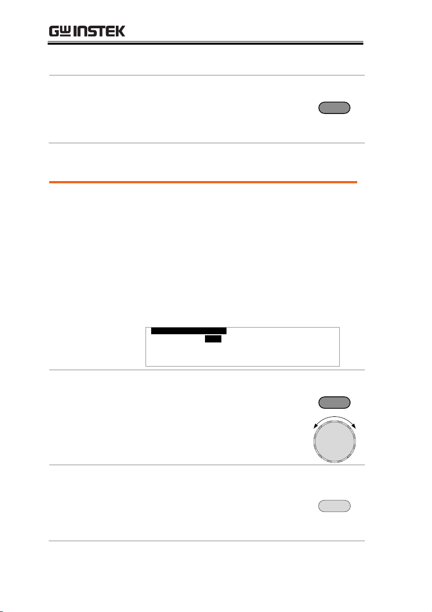
Description
The TEST Utility menu is accessed by pressing
the UTILITY key when the tester is in EDIT
status.
The TEST Utility settings are configured for
each test function (DCW or ACW) separately.
The settings include: ARC MODE (ACW,
DCW), and FREQUENCY (ACW).
T E S T U T I
L TI Y
F R E Q U E N C Y : 6 0 H Z
A R C M O D E : O F F
MT I E = 0 0R
MT I E = 0 0R
MT I E = 0 0R
MT I E = 0 0R
Select a Setting.
Use the FIELD key to highlight a test setting.
Use the scroll wheel to choose a parameter for the
setting.
FIELD
Save the TEST Utility Settings
To save any changes, press the SAVE key.
SAVE
The tester will return to EDIT status.
TEST Utility Settings
20
Page 21

OPERATION
Cancel and Exit the TEST Utility Menu
To exit and cancel any changes, press the ESC key.
ESC
The tester will return to EDIT status.
21
 Loading...