

Page 1

Arbitrary Function Generator
AFG-2000 Series
QUICK START GUIDE
GW INSTEK PART NO. 82AF-21200MC1
ISO-9001 CERTIFIED MANUFACTURER
Page 2

This manual contains proprietary information, which is protected by
copyright. All rights are reserved. No part of this manual may be
photocopied, reproduced or translated to another language without
prior written consent of Good Will Corporation.
The information in this manual was correct at the time of printing.
However, Good Will continues to improve its products and therefore
reserves the right to change the specifications, equipment, and
maintenance procedures at any time without notice.
Good Will Instrument Co., Ltd.
No. 7-1, Jhongsing Rd., Tucheng Dist., New Taipei City 236, Taiwan.
Page 3

TABLE OF CONTENTS
Table of Contents
SAFETY INSTRUCTIONS .................................. 2
GETTING STARTED ......................................... 6
Main Features ..................................................................... 6
Panel Overview .................................................................... 8
Selecting a Waveform ........................................................ 14
ARB ................................................................................... 15
Modulation ........................................................................ 15
Sweep (2100 series only) ................................................... 17
Counter (2100 series only) ................................................ 17
Save/Recall ........................................................................ 18
AFG-2000 Series Specifications ......................................... 19
EC Declaration of Conformity ............................................ 23
1
Page 4
AFG-2000 Quick Start Guide
WARNING
Warning: Identifies conditions or practices that
could result in injury or loss of life.
CAUTION
Caution: Identifies conditions or practices that
could result in damage to the function generator or
to other objects or property.
DANGER High Voltage
Attention: Refer to the Manual
Protective Conductor Terminal
Earth (Ground) Terminal
DANGER Hot Surface
SAFETY INSTRUCTIONS
This chapter contains important safety instructions
that should be followed when operating and
storing the function generator. Read the following
before any operation to ensure your safety and to
keep the function generator in the best condition.
Safety Symbols
These safety symbols may appear in this manual or on the
instrument.
2
Page 5
SAFETY INSTRUCTIONS
Double Insulated
Do not dispose electronic equipment as unsorted
municipal waste. Please use a separate collection
facility or contact the supplier from which this
instrument was purchased.
General
Guideline
CAUTION
Do not place heavy objects on the instrument.
Do not place flammable objects on the
instrument.
Avoid severe impact or rough handling that
may damage the function generator.
Avoid discharges of static electricity on or near
the function generator.
Use only mating connectors, not bare wires, for
the terminals.
The instrument should only be disassembled by
a qualified technician.
(Measurement categories) EN 61010-1:2010 specifies the
measurement categories and their requirements as follows. The
instrument falls under category II.
Measurement category IV is for measurement performed at the
source of a low-voltage installation.
Measurement category III is for measurement performed in a
building installation.
Measurement category II is for measurement performed on
circuits directly connected to a low voltage installation.
Measurement category I is for measurements performed on
circuits not directly connected to Mains.
Power Supply
WARNING
AC Input voltage: 100 ~ 240V AC, 50 ~ 60Hz.
Connect the protective grounding conductor of
the AC power cord to an earth ground to
prevent electric shock.
Safety Guidelines
3
Page 6
AFG-2000 Quick Start Guide
Fuse
WARNING
Fuse type: F1A/250V.
Only qualified technicians should replace the
fuse.
To ensure fire protection, replace the fuse only
with the specified type and rating.
Disconnect the power cord and all test leads
before replacing the fuse.
Make sure the cause of fuse blowout is fixed
before replacing the fuse.
Cleaning the
function
generator
Disconnect the power cord before cleaning the
function generator.
Use a soft cloth dampened in a solution of mild
detergent and water. Do not spray any liquid
into the function generator.
Do not use chemicals containing harsh products
such as benzene, toluene, xylene, and acetone.
Operation
Environment
Location: Indoor, no direct sunlight, dust free,
almost non-conductive pollution (Note below)
and avoid strong magnetic fields.
Relative Humidity: < 80%
Altitude: < 2000m
Temperature: 0°C to 40°C
(Pollution Degree) EN 61010-1:2010 specifies pollution degrees and
their requirements as follows. The function generator falls under
degree 2.
Pollution refers to “addition of foreign matter, solid, liquid, or
gaseous (ionized gases), that may produce a reduction of dielectric
strength or surface resistivity”.
Pollution degree 1: No pollution or only dry, non-conductive
pollution occurs. The pollution has no influence.
Pollution degree 2: Normally only non-conductive pollution
occurs. Occasionally, however, a temporary conductivity caused
by condensation must be expected.
Pollution degree 3: Conductive pollution occurs, or dry, non-
conductive pollution occurs which becomes conductive due to
condensation which is expected. In such conditions, equipment
is normally protected against exposure to direct sunlight,
4
Page 7
SAFETY INSTRUCTIONS
precipitation, and full wind pressure, but neither temperature
nor humidity is controlled.
Storage
environment
Location: Indoor
Relative Humidity: < 70%
Temperature: -10°C to 70°C
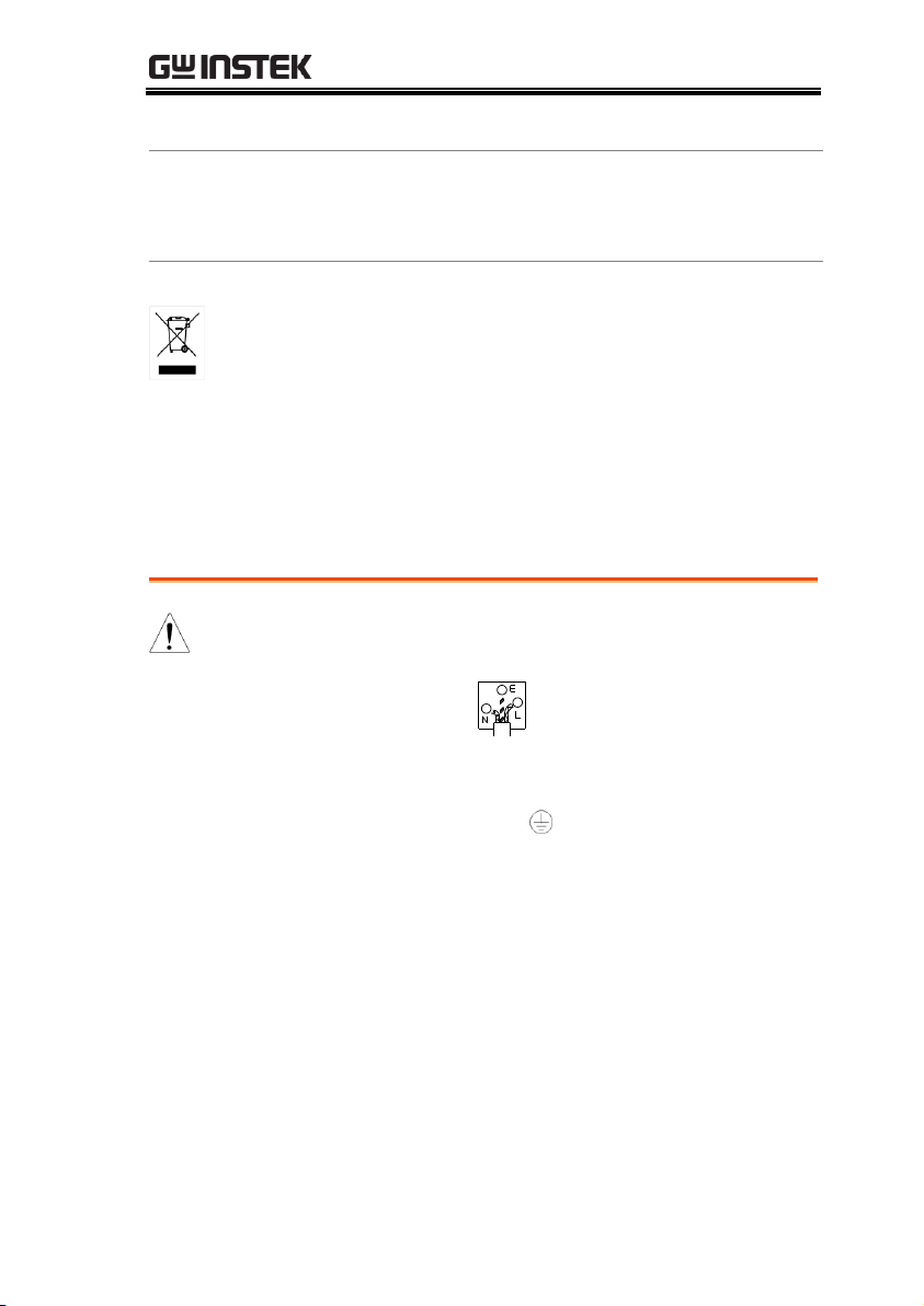
Disposal
Do not dispose this instrument as unsorted
municipal waste. Please use a separate collection
facility or contact the supplier from which this
instrument was purchased. Please make sure
discarded electrical waste is properly recycled to
reduce environmental impact.
Green/ Yellow:
Earth Blue:
Neutral
Brown:
Live (Phase)
Power cord for the United Kingdom
When using the function generator in the United Kingdom, make sure the
power cord meets the following safety instructions.
NOTE: This lead/appliance must only be wired by competent persons
WARNING: THIS APPLIANCE MUST BE EARTHED
IMPORTANT: The wires in this lead are coloured in accordance with the following code:
As the colours of the wires in main leads may not correspond with the coloured
marking identified in your plug/appliance, proceed as follows:
The wire which is coloured Green & Yellow must be connected to the Earth terminal
marked with either the letter E, the earth symbol or coloured Green/Green &
Yellow.
The wire which is coloured Blue must be connected to the terminal which is marked
with the letter N or coloured Blue or Black.
The wire which is coloured Brown must be connected to the terminal marked with
the letter L or P or coloured Brown or Red.
If in doubt, consult the instructions provided with the equipment or contact the
supplier.
This cable/appliance should be protected by a suitably rated and approved HBC
mains fuse: refer to the rating information on the equipment and/or user instructions
for details. As a guide, a cable of 0.75mm2 should be protected by a 3A or 5A fuse.
Larger conductors would normally require 13A types, depending on the connection
method used.
Any exposed wiring from a cable, plug or connection that is engaged in a live socket
is extremely hazardous. If a cable or plug is deemed hazardous, turn off the mains
power and remove the cable, any fuses and fuse assemblies. All hazardous wiring
must be immediately destroyed and replaced in accordance to the above standard.
5
Page 8
AFG-2000 Quick Start Guide
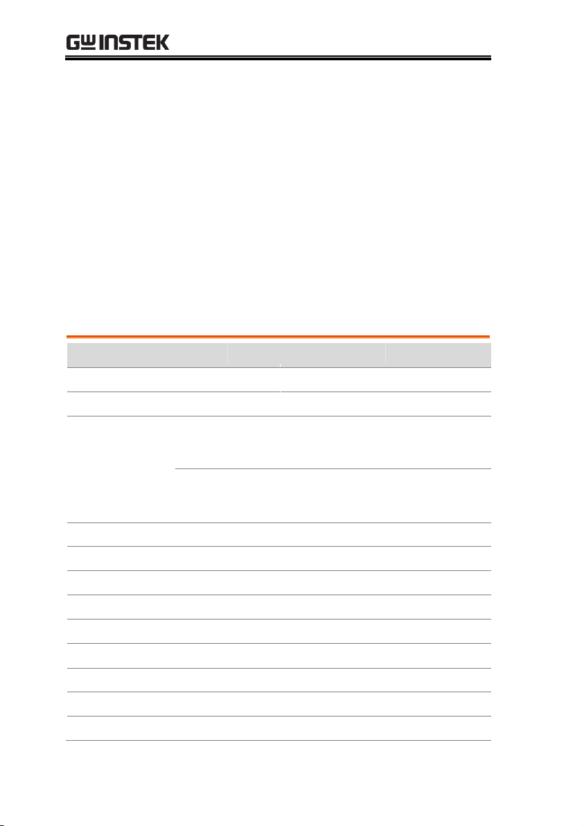
Model name
AFG-2005
AFG-2105
AFG-2012
AFG-2112
AFG-2025
AFG-2125
Frequency Range
0.1Hz~5MHz
0.1Hz~12MHz
0.1Hz~25MHz
Output waveform
Sine, Square, Ramp, Noise, ARB
Amplitude range
0.1Hz~20MHz
1 mVpp to 10 Vpp( into 50Ω)
2 mVpp to 20 Vpp(open-circuit)
20MHzHz~25MHz
1 mVpp to 5 Vpp( into 50Ω)
2 mVpp to 10 Vpp(open-circuit)
Variable Offset
Variable Duty
SYNC (TTL) ouput
Save/Recall
Sweep operation
— — —
AM
— — —
FM
— — —
FSK
— — —
Frequency Counter
— — —
GETTING STARTED
The Getting started chapter introduces the
function generator’s main features, appearance
and introduces a quick instructional summary of
some of the basic functions. For comprehensive
operation instructions, please see the user manual.
Main Features
6
Page 9

GETTING STARTED
ARB
USB Interface
Performance
DDS technology using an FPGA provides high
resolution waveforms
25MHz DDS (Direct Digital Synthesis) signal
output series
0.1Hz resolution
Full Function Arbitrary Waveform Capability
20 MSa/s sample rate
10 MHz repetition rate
4 k-point waveform length
10-bit amplitude resolution
Ten 4k waveform memories
Features
Sine, Square, Ramp, Noise
Int/Ext AM, FM, FSK modulation
Modulation/sweep signal output
Save/recall 10 groups of setting memories
Output overload protection
ARB (Arbitrary Waveform) can be edited with
PC software
Interface
USB interface as standard
3.5 inch LCD
7
Page 10

AFG-2000 Quick Start Guide
ARB
OUTPUT
50
W
50
W
SYNC
MAIN
OUTPUT
POWER
Save/Recall INT/EXT Hop LIN/LOG
Shape DEP/DEV Rate Start/Stop Gate
FUNC
FREQ
AMPL
OFST
DUTY
Point
Value
0
7 8 9
4 5 6
1 2 3
/
Hz/Vpp kHz/Vrms MHz/dBm % Shift
AM FM FSK Sweep Count
OUTPUT
Enter
Arbitrary Function Generator
AFG-2125
LCD Display Number
pad
Scroll Wheel
MAIN
output port
ARB keys Power
button
Output
control key
Enter key
Arrow keys SYNC output port
Operation
keys
Function keys
High-Z/50Ω
ARB
OUTPUT
50
W
50
W
SYNC
MAIN
OUTPUT
POWER
Save/Recall
FUNC
FREQ
AMPL
OFST
DUTY
Point
Value
0
7 8 9
4 5 6
1 2 3
/
Hz/Vpp kHz/Vrms MHz/dBm % Shift
OUTPUT
Enter
Arbitrary Function Generator
AFG-2025
LCD Display Number
pad
Scroll Wheel
MAIN
output port
ARB keys Power
button
Output
control key
Enter key
Arrow keys SYNC output port
Operation
keys
Function keys
High-Z/50Ω
Panel Overview
AFG-2105/2112/2125 Front Panel
AFG-2005/2012/2025 Front Panel
8
Page 11

GETTING STARTED
LCD display
3.5 inch, 3 color LCD display.
Keypad
0
/
321
4
7 859
6
The digital keypad is used to
enter values and parameters. The
keypad is often used in
conjunction with the selection
keys and variable knob.
Scroll Wheel
The scroll wheel is used to edit
values and parameters in steps of
1 digit. Used in conjunction with
the arrow keys.
Decrease Increase
Arrow keys
Used to select digits when editing
parameters.
Output ports
OUTPUT
50
W
50
W
SYNC
MAIN
OUTPUT
SYNC output port (50Ω
impedance).
Main output port (50Ω
impedance).
Enter key
Enter
Used to confirm input values.
Power button
POWER
Turns the instrument power
on/off.
Output control
key
OUTPUT
Turns the output on/off.
Output
Impedance
Shift
+
High Z/50Ω
OUTPUT
Toggles the output impedance
between 50Ω and High-Z.
9
Page 12

Operation keys
Hz/Vpp
Selects Hz or Vpp units.
Shift
+
Save/Recall
Hz/Vpp
Saves or recalls waveforms from
memory.
kHz/Vrms
Selects kHz or Vrms units.
Shift
+
INT/EXT
kHz/Vrms
Sets the source to internal or
external for the modulation and
FSK functions*.
MHz/dBm
Selects MHz or dBm units.
Shift
+
Hop
MHz/dBm
Sets the “Hop” frequency for FSK
modulation*.
%
Selects % units.
Shift
+
LIN/LOG
%
Sets the sweep to linear or
logarithmic*.
Shift
The shift key is used to select the
secondary functions on the
operation keys.
AM
The AM key is used to turn AM
modulation on/off*.
Shift
+
Shape
AM
Selects the modulation
waveform*.
FM
The FM key is used to turn FM
modulation on/off*.
Shift
+
DEP/DEV
FM
Selects the modulation depth or
the frequency deviation*.
FSK
Selects FSK modulation*.
Shift
+
Rate
FSK
Sets the AM, FM, FSK modulation
and sweep function (Rate)*
AFG-2000 Quick Start Guide
10
Page 13

GETTING STARTED
Sweep
Selects the Sweep function*.
Shift
+
Start/Stop
Sweep
Sets the Start or Stop frequency*.
Count
Turns the frequency counter
on/off*.
Shift
+
Gate
Count
Sets the frequency counter gate
time*.
ARB edit keys
ARB
Value
Point
Arbitrary waveform editing keys.
The point key sets the ARB point
numbers.
The Value key sets the amplitude
value of the selected point.
Function keys
FUNC
The FUNC key is used to select
the output waveform type,
Sine, Square, Ramp, Noise, ARB.
FREQ
Sets the frequency of the selected
waveform.
AMPL
Sets the amplitude of the selected
waveform.
OFST
The OFST sets the DC offset for
the selected waveform.
DUTY
The DUTY key sets the duty cycle
of square and ramp waveforms.
*indicates functions/features for the AFG-2105/2112/2125 only.
11
Page 14

AFG-2000 Quick Start Guide
NO OPERATOR SERVICEABLE COMPONENTS INSIDE.
DO NOT REMOVE COVERS. REFER SERVICING TO
TO AVOID ELECTRIC SHOCK THE POWER CORD PROTECTIVE
GROUNDING CONDUCTOR MUST BE CONNECTED TO GROUND.
WARNING
QUALIFIED PERSONNEL.
SER.NO. LABEL
AC 100-240V
50-60Hz 25VA
OUTPUT INPUT
MOD Counter
Trigger MOD
MOD input
Trigger input
MOD output
Type B USB portPower socket
Counter input
NO OPERATOR SERVICEABLE COMPONENTS INSIDE.
DO NOT REMOVE COVERS. REFER SERVICING TO
TO AVOID ELECTRIC SHOCK THE POWER CORD PROTECTIVE
GROUNDING CONDUCTOR MUST BE CONNECTED TO GROUND.
WARNING
QUALIFIED PERSONNEL.
SER.NO. LABEL
AC 100-240V
50-60Hz 25VA
Type B USB portPower socket
MOD output
OUTPUT INPUT
MOD Counter
Trigger MOD
Modulation output port.
Counter input
Counter input port.
MOD input
Modulation input port.
Trigger input
Trigger input port.
Type B USB port
The type B USB port is used to
connect the function generator to a
PC for remote control.
Power Socket
Input
AC 100-240V
50-60Hz 25VA
Power input: 100~240V AC
50~60Hz.
AFG-2105/2112/2125 Rear Panel
AFG-2005/2012/2025 Rear Panel
12
Page 15
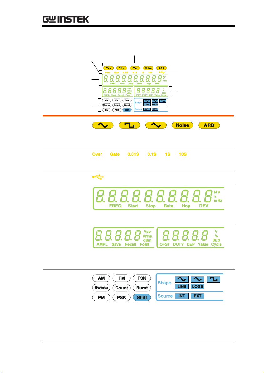
Display
Waveform type
Counter settings
USB icon
Frequency display
Secondary parameter
display
Modulation, sweep,
counter menu
Waveform type
Press the function key to cycle through different
output waveforms.
Counter settings
Gate time counter settings*.
USB icon
Shows the USB interface status.
Frequency
Display
Displays the main waveform frequency settings.
Secondary
parameter display
Displays secondary waveform parameters and
settings.
Modulation,
sweep, counter
menu
Displays the modulation, sweep and counter
functions as well as the modulating waveform and
source*.
*indicates functions/features for the AFG-2105/2112/2125 only.
GETTING STARTED
13
Page 16

AFG-2000 Quick Start Guide
Example: Sine Wave, 10kHz, 1Vpp, 2Vdc
Output
50
W
MAIN
1. Press FUNC>select the sine wave
2. Press FREQ>1>0>kHz
3. Press AMPL>1>Vpp
4. Press OFST>2>Vpp
5. Press OUTPUT
Example: Square Wave, 10kHz, 3Vpp, 75% duty cycle
Output
50
W
MAIN
1. Press FUNC>select the square wave
2. Press FREQ>1>0>kHz
3. Press AMPL>3>Vpp
4. Press DUTY>7>5>%
5. Press OUTPUT
Example: Ramp Wave, 10kHz, 3Vpp, 25% symmetry
Output
50
W
MAIN
1. Press FUNC>select the ramp wave
2. Press FREQ>1>0>kHz
3. Press AMPL>3>Vpp
4. Press DUTY>2>5>%
5. Press OUTPUT
Selecting a Waveform
Sine Wave
Square Wave
Ramp Wave
14
Page 17

GETTING STARTED
Example: ARB Ramp, 10 kHz, 1Vpp, 2 points.
Output
50
W
MAIN
1. Press FUNC>select the ARB wave
2. Press FREQ>1>0>kHz
3. Press AMPL>1>Vpp
4. Press Point>0>Enter
5. Press Value>5>1>1>Enter. (+511 amplitude)
6. Press Point>1>Enter
7. Press Value>+/->5>1>1>Enter. (-511
amplitude)
8. Press OUTPUT
Example: AM modulation. 100Hz modulating square wave. 1 Vpp,
1kHz Sine wave carrier. 70% modulation depth. Internal source
signal.
Output
50
W
MAIN
1. Press FUNC>select the sine wave
2. Press FREQ>1>kHz
3. Press AMPL>1>Vpp
4. Press AM
5. Press Shift>INT/EXT>select INT source
6. Press Shift>Shape>select the square wave
7. Press Shift>Rate>1>0>0>Hz
8. Press Shift>DEP/DEV>7>0>%
9. Press Output
10. Press AM to deselect the AM function
ARB
ARB – Enter Points
Modulation
AM (2100 series only)
15
Page 18

AFG-2000 Quick Start Guide
Example: FM modulation. 100Hz modulating square wave. 1Vpp,
1kHz Sine wave carrier. 100 Hz frequency deviation. Internal
Source.
Output
50
W
MAIN
1. Press FUNC>select the sine wave
2. Press FREQ>1>kHz
3. Press AMPL>1>Vpp
4. Press FM
5. Press Shift>INT/EXT>select INT
6. Press Shift>Shape>select square
7. Press Shift>Rate>1>0>0>Hz
8. Press Shift>DEP/DEV>1>0>0>Hz
9. Press Output
10. Press FM to deselect the FM function
Example: FSK modulation. 100Hz Hop frequency. 1Vpp, 1kHz
Ramp carrier wave. 10 Hz Rate (modulation frequency). Internal
Source.
Output
50
W
MAIN
1. Press FUNC>select the ramp wave
2. Press FREQ>1>kHz
3. Press AMPL>1>Vpp
4. Press FSK
5. Press Shift>INT/EXT>Select INT
6. Press Shift>Rate>1>0>Hz
7. Press Shift>HOP>1>0>0>Hz
8. Press Output
9. Press FSK to deselect the FSK function
FM (2100 series only)
FSK Modulation (2100 series only)
16
Page 19

GETTING STARTED
Example: Frequency Sweep. Start Frequency 1Hz, Stop Frequency
1MHz. 1Hz Rate. 1Vpp. Lins Sweep.
Output
50
W
MAIN
1. Press FUNC>select the ramp wave
2. Press AMPL>1>Vpp
3. Press Sweep
4. Press Shift>INT/EXT>select INT
5. Press Shift>Start/Stop>select Start>1>Hz
6. Press Shift>Start/Stop>select Stop>1>MHz
7. Press Shift>Rate>1>Hz
8. Press Shift>LIN/LOG>Select LINS
9. Press Output
10. Press Sweep to deselect the sweep function
Example: Frequency counter function, gate time 1s.
Input
OUTPUT INPUT
MOD Counter
MOD
Trigger
1. Press Count
2. Press Shift>Gate>select 1S gate time
3. Connect the signal to the counter input
terminal.
4. Press Count to deselect the counter function.
Sweep (2100 series only)
Counter (2100 series only)
17
Page 20

AFG-2000 Quick Start Guide
Example: Save waveform to memory.
1. Press Shift>Save/Recall>Select Save
2. Turn the Scroll knob>select a file
number>Enter
Example: Recall waveform from memory.
1. Press Shift>Save/Recall>Select Recall
2. Turn the Scroll knob>select a file
number>Enter
Save/Recall
Save
Recall
18
Page 21

GETTING STARTED
AFG-2000 models
2005
2012
2025
2105
2112
2125
Waveforms
Sine, Square, Ramp, Noise, ARB
Arbitrary Functions
Sample Rate
20 MSa/s
Repetition Rate
10MHz
Waveform Length
4k points
Amplitude
Resolution
10 bits
Non-Volatile
Memory
4k points
Frequency Characteristics
Range
Sine
0.1Hz~
5MHz
0.1Hz~
12MHz
0.1Hz~
25MHz
0.1Hz~
5MHz
0.1Hz~
12MHz
0.1Hz~
25MHz
Square
0.1Hz~
5MHz
0.1Hz~
12MHz
0.1Hz~
25MHz
0.1Hz~
5MHz
0.1Hz~
12MHz
0.1Hz~
25MHz
Triangle, Ramp
1MHz
Resolution 0.1Hz
Accuracy
Stability
±20 ppm
Aging
±1 ppm, per 1 year
Tolerance
≤ 1 mHz
Output Characteristics
Amplitude
Range
1 mVpp to 10 Vpp( into 50Ω)
2 mVpp to 20 Vpp(open-circuit)
1 mVpp to 5 Vpp( into 50Ω) for 20MHz-
25MHz
2 mVpp to 10 Vpp(open-circuit) for
20MHz-25MHz
Accuracy
± 2% of setting ±1 mVpp
(at 1 kHz)
Resolution
1 mV or 3 digits
Flatness
± 1% (0.1dB) ≤100kHz
± 3% (0.3 dB) ≤5MHz
± 5% (0.4 dB) ≤12MHz
±20%(2dB)≤20MHz
± 5% (0.4 dB) ≤25MHz
(sine wave relative to 1 kHz)
Units
Vpp, Vrms, dBm
AFG-2000 Series Specifications
The specifications apply when the function generator is powered on
for at least 30 minutes under +20°C~+30°C.
19
Page 22

AFG-2000 Quick Start Guide
Offset
Range
±5 Vpk ac +dc (into 50Ω)
±10Vpk ac +dc (Open circuit)
±2.5 Vpk ac +dc (into 50Ω) for 20MHz-
25MHz
±5Vpk ac +dc (Open circuit) for 20MHz-
25MHz
Accuracy
2% of setting + 5 mV+ 0.5% of amplitude
Waveform Output
Impedance
50Ω typical (fixed)
> 300kΩ (output disabled)
Attenuator
—
Protection
Short-circuit protected
Overload relay automatically disables
main output
SYNC Output
Level
TTL-compatible into>1kΩ
Impedance
50Ω nominal
Fan Out
—
Rise of Fall Time
≤ 25ns
Sine wave Characteristics
Harmonic
distortion(5)
–55 dBc DC ~ 200kHz, Ampl > 0.1Vpp
–50 dBc 200kHz ~ 1MHz, Ampl > 0.1Vpp
–35 dBc 1MHz ~ 5MHz, Ampl > 0.1Vpp
–30 dBc 5MHz ~ 25MHz, Ampl > 0.1Vpp
Square wave Characteristics
Rise/Fall Time
≤25ns at maximum output.
(into 50 Ω load)
Overshoot
<5%
Asymmetry
1% of period +1 ns
Variable duty
Cycle
1.0% to 99.0% ≤100kHz
20.0% to 80.0% ≤ 5MHz
40.0% to 60.0% ≤ 10MHz
50% ≤ 25MHz
Ramp Characteristics
Linearity
< 0.1% of peak output
Variable
Symmetry
0% to 100% (0.1% Resolution)
20
Page 23

GETTING STARTED
AM Modulation
Carrier Waveforms
—
Sine, Square,
Triangle
Modulating
Waveforms
—
Sine, Square,
Triangle
Modulating
Frequency
—
2mHz to
20kHz (Int)
DC to 20kHz (Ext)
Depth — 0% to 120.0%
Source
—
Internal / External
FM Modulation
Carrier Waveforms
—
Sine, Square,
Triangle
Modulating
Waveforms
—
Sine, Square,
Triangle
Modulating
Frequency
—
2mHz to
20kHz (Int)
DC to 20kHz (Ext)
Peak Deviation
—
DC to Max
Frequency
Source
—
Internal / External
Sweep
Waveforms
—
Sine, Square,
Triangle
Type — Linear or
Logarithmic
Start/Stop Freq
—
0.1Hz to Max
Frequency
Sweep Time
—
1ms to 500s
Source
—
Internal / External
FSK
Carrier Waveforms
—
Sine, Square,
Triangle
Modulating
Waveforms
—
50% duty cycle
square
Modulation Rate
—
2mHz to
100kHz(INT)
DC to 100kHz(Ext)
Frequency Range
—
0.1Hz to Max
Frequency
Source
—
Internal / External
21
Page 24

AFG-2000 Quick Start Guide
Frequency Counter
Range — 5Hz to 150MHz
Accuracy — Time Base
accuracy±1count
Time Base
—
±20ppm (23˚C
±5˚C) after 30
minutes warm up
Resolution
—
The maximum
resolution is:
100nHz for 1Hz,
0.1Hz for 100MHz.
Input Impedance
—
1kΩ/1pf
Sensitivity
—
35mVrms ~ 30Vms
(5Hz to 150MHz)
Save/Recall
10 Groups of Setting Memories
(Locations 0~9 only for instrument state,
Locations 10~19 only for ARB data)
Interface USB (Device)
Display
LCD
General Specifications
Power Source
AC100~240V, 50~60Hz
Power
Consumption
25 VA (Max)
Operating
Environment
Temperature to satisfy the specification :
18 ~ 28˚C
Operating temperature :
0 ~ 40˚C
Relative Humidity:
≤ 80%, 0 ~ 40˚C
≤ 70%, 35 ~ 40˚C
Installation category: CAT Ⅱ
Operating
Altitude
2000 Meters
Storage
Temperature
-10~70˚C, Humidity: ≤70%
Dimensions
(WxHxD)
266(W) x 107(H) x 293(D) mm
Weight
Approx. 2.5kg
Accessories
GTL-101× 1
GTL-101× 2
Quick Start Guide ×1
CD (user manual + software) ×1
Power cord×1
22
Page 25

GETTING STARTED
We
GOOD WILL INSTRUMENT CO., LTD.
No.7-1, Jhongsing Rd., Tucheng Dist., New Taipei City 236, Taiwan
GOOD WILL INSTRUMENT (SUZHOU) CO., LTD.
No. 69, Lushan Road, Suzhou New District Jiangsu, China
declares that the below mentioned product
AFG-2005, AFG-2105, AFG-2012, AFG-2112, AFG-2025, AFG-2125
Are herewith confirmed to comply with the requirements set out in the
Council Directive on the Approximation of the Law of Member States
relating to Electromagnetic Compatibility (2004/108/EC) and Low
Voltage Equipment Directive (2006/95/EC). For the evaluation
regarding the Electromagnetic Compatibility and Low Voltage
Equipment Directive, the following standards were applied:
◎ EMC
EN 61326-1 :
Electrical equipment for measurement, control and
laboratory use –– EMC requirements (2006)
Conducted and Radiated Emissions
EN 55011: 2009+A1:2010
Electrostatic Discharge
EN 61000-4-2: 2008
Current Harmonic
EN 61000-3-2: 2006+A2:2009
Radiated Immunity
EN 61000-4-3: 2006+ A2:2010
Voltage Fluctuation
EN 61000-3-3: 2008
Electrical Fast Transients
EN 61000-4-4: 2004+A1:2010
-------------------------
Surge Immunity
EN 61000-4-5: 2005
-------------------------
Conducted Susceptibility
EN 61000-4-6: 2008
-------------------------
Power Frequency Magnetic Field
EN 61000-4-8: 2009
-------------------------
Voltage Dips/ Interrupts
EN 61000-4-11: 2004
◎ Safety
Low Voltage Equipment Directive 2006/95/EC
Safety Requirements
EN 61010-1: 2010
EC Declaration of Conformity
23
 Loading...