

Page 1

Arbitrary Function Generator
AFG-125/AFG-225/AFG-125P/AFG-225P
USER MANUAL
GW INSTEK PART NO. 82AF-12500E01
ISO-9001 CERTIFIED MANUFACTURER
Page 2

This manual contains proprietary information, which is protected by
copyright. All rights are reserved. No part of this manual may be
photocopied, reproduced or translated to another language without
prior written consent of Good Will Corporation.
The information in this manual was correct at the time of printing.
However, Good Will continues to improve its products and therefore
reserves the right to change the specifications, equipment, and
maintenance procedures at any time without notice.
Good Will Instrument Co., Ltd.
No. 7-1, Jhongsing Rd., Tucheng Dist., New Taipei City 236, Taiwan.
Page 3

Table of Contents
Table of Contents
SAFETY INSTRUCTIONS.................................. 7
Safety Symbols .......................................................................7
Safety Guidelines.................................................................... 8
GETTING STARTED........................................ 11
Main Features ...................................................................11
Panel Overview..................................................................13
Front Panel ...........................................................................13
Rear Panel............................................................................. 14
System Requirements.........................................................15
Software Installation ............................................................15
Setup the Signal Generator..................................................16
Default Settings ................................................................17
REMOTE INTERFACE ..................................... 19
Establishing a Remote Connection ....................................19
Configure USB interface.......................................................19
Remote control terminal connection...................................20
Command Syntax .................................................................21
System Command .............................................................26
SYSTem:ERRor? ...................................................................26
*IDN? ...................................................................................26
*RST .....................................................................................27
SYSTem:VERSion?................................................................27
*OPC ....................................................................................27
*OPC?................................................................................... 28
*WAI ..................................................................................... 28
Status Register Commands ...............................................29
*CLS......................................................................................29
*ESE...................................................................................... 29
*ESR?....................................................................................30
*STB?.................................................................................... 30
*SRE .....................................................................................31
Apply Commands ..............................................................32
SOURce[1|2]:APPLy:SINusoid..............................................34
SOURce[1|2]:APPLy:SQUare ................................................ 34
SOURce[1|2]:APPLy:RAMP...................................................35
3
Page 4

AFG-200 SERIES USER MANUAL
SOURce[1|2]:APPLy:PULSe.................................................. 35
SOURce[1|2]:APPLy:NOISe.................................................. 36
SOURce[1|2]:APPLy:USER ...................................................36
SOURce[1|2]:APPLy?............................................................ 37
Output Commands............................................................38
SOURce[1|2]:FUNCtion .......................................................38
SOURce[1|2]:FREQuency ..................................................... 39
SOURce[1|2]:AMPlitude....................................................... 41
SOURce[1|2]:DCOffset......................................................... 42
SOURce[1|2]:SQUare:DCYCle.............................................. 43
SOURce[1|2]:RAMP:SYMMetry............................................ 44
OUTPut[1|2] .........................................................................45
OUTPut[1|2]:LOAD .............................................................. 45
SOURce[1|2]:VOLTage:UNIT............................................... 46
Pulse Configuration Commands ........................................48
SOURce[1|2]:PULSe:PERiod ................................................48
SOURce[1|2]:PULSe:WIDTh................................................. 49
Amplitude Modulation (AM) Commands ...........................50
AM Overview........................................................................ 50
SOURce[1|2]:AM:STATe....................................................... 51
SOURce[1|2]:AM:INTernal:FUNCtion ................................. 51
SOURce[1|2]:AM:INTernal:FREQuency............................... 52
SOURce[1|2]:AM:DEPTh...................................................... 52
Frequency Modulation (FM) Commands............................54
FM Overview........................................................................ 54
SOURce[1|2]:FM:STATe....................................................... 55
SOURce[1|2]:FM:INTernal:FUNCtion .................................55
SOURce[1|2]:FM:INTernal:FREQuency............................... 56
SOURce[1|2]:FM:DEViation................................................. 56
Frequency-Shift Keying (FSK) Commands ..........................59
FSK Overview ....................................................................... 59
SOURce[1|2]:FSKey:STATe................................................... 59
SOURce[1|2]:FSKey:FREQuency .......................................... 60
SOURce[1|2]:FSKey:INTernal:RATE..................................... 61
Phase Modulation (PM)Commands ...................................62
PM Overview........................................................................ 62
SOURce[1|2]:PM:STATe....................................................... 63
SOURce[1|2]:PM:INTernal:FUNction.................................. 63
SOURce[1|2]:PM:INTernal:FREQuency............................... 64
SOURce[1|2]:PM:DEViation................................................. 64
SUM Modulation (SUM) Commands ..............................66
SUM Overview .....................................................................66
SOURce[1|2]:SUM:STATe .................................................... 67
4
Page 5

Table of Contents
SOURce[1|2]:SUM:INTernal:FUNction................................67
SOURce[1|2]:SUM:INTernal:FREQuency.............................68
SOURce[1|2]:SUM:AMPL.....................................................68
Frequency Sweep Commands ............................................70
Sweep Overview ...................................................................70
SOURce[1|2]:SWEep:STATe ................................................. 71
SOURce[1|2]:FREQuency:STARt ..........................................72
SOURce[1|2]:FREQuency:STOP...........................................72
SOURce[1|2]:FREQuency:CENTer........................................73
SOURce[1|2]:FREQuency:SPAN........................................... 74
SOURce[1|2]:SWEep:SPACing..............................................75
SOURce[1|2]:SWEep:TIME................................................... 75
SOURce[1|2]:SWEep:SOURce.............................................. 76
SOURce[1|2]:MARKer:FREQuency....................................... 77
SOURce[1|2]:MARKer........................................................... 77
Burst Mode Commands.....................................................79
Burst Mode Overview...........................................................79
SOURce[1|2]:BURSt:STATe..................................................81
SOURce[1|2]:BURSt:MODE ................................................. 81
SOURce[1|2]:BURSt:NCYCles..............................................82
SOURce[1|2]:BURSt:INTernal:PERiod .................................83
SOURce[1|2]:BURSt:PHASe................................................. 83
SOURce[1|2]:BURSt:TRIGger:SOURce ................................ 84
SOURce[1|2]:BURSt:TRIGger:DELay....................................85
SOURce[1|2]:BURSt:TRIGger:SLOPe................................... 86
SOURce[1|2]:BURSt:GATE:POLarity .................................... 86
SOURce[1|2]:BURSt:OUTPut:TRIGger:SLOPe ....................87
SOURce[1|2]:BURSt:OUTPut[1|2]:TRIGger..........................88
Arbitrary Waveform Commands .........................................89
Arbitrary Waveform Overview..............................................89
SOURce[1|2]:FUNCtion USER .............................................90
SOURce[1|2]:DATA:DAC ...................................................... 90
SOURce[1|2]:ARB:EDIT:COPY .............................................91
SOURce[1|2]:ARB:EDIT:DELete ...........................................92
SOURce[1|2]:ARB:EDIT:DELete:ALL .................................... 92
SOURce[1|2]:ARB:EDIT:POINt.............................................92
SOURce[1|2]:ARB:EDIT:LINE............................................... 93
SOURce[1|2]:ARB:EDIT:PROTect.........................................93
SOURce[1|2]:ARB:EDIT:PROTect:ALL .................................94
SOURce[1|2]:ARB:EDIT:UNProtect......................................94
SOURce[1|2]:ARB:OUTPut...................................................94
Phase ................................................................................95
SOURce[1|2]:PHASe............................................................. 95
SOURce[1|2]:PHASe:SYNChronize......................................95
5
Page 6

AFG-200 SERIES USER MANUAL
Couple...............................................................................96
SOURce[1|2]:FREQuency:COUPle:MODE .......................... 96
SOURce[1|2]:FREQuency:COUPle:OFFSet.......................... 96
SOURce[1|2]:FREQuency:COUPle:RATio ............................ 97
SOURce[1|2]:AMPlitude:COUPle:STATe ............................. 97
SOURce[1|2]:TRACk............................................................. 97
Sync ..................................................................................99
OUTPut:SYNC...................................................................... 99
OUTPut[1|2]:SYNC:MODE .................................................. 99
OUTPut[1|2]:SYNC:POLarity.............................................. 100
OUTPut:SYNC:SOURce..................................................... 101
Power Commands............................................................102
VOUTput............................................................................ 102
VSET ................................................................................... 102
Save and Recall Commands .............................................104
*SAV................................................................................... 104
*RCL ................................................................................... 104
MEMory:STATe:DELete .....................................................104
MEMory:STATe:DELete ALL .............................................. 105
Error Messages................................................................106
Command Error Codes...................................................... 106
Execution Errors................................................................. 108
Query Errors....................................................................... 115
Arbitrary Waveform Errors................................................. 115
SCPI Status Register........................................................117
Register types..................................................................... 117
AFG-200 SERIES Status System ........................................ 118
Questionable Status Register ............................................ 119
Standard Event Status Registers ....................................... 119
The Status Byte Register .................................................... 121
Output Queue.................................................................... 122
Error Queue........................................................................ 122
APPDENIX.................................................... 123
AFG-200 Specifications....................................................123
6
Page 7

TABLE OF CONTENTS
SAFETY INSTRUCTIONS
This chapter contains important safety instructions
that should be followed when operating and
storing the function generator. Read the following
before any operation to ensure your safety and to
keep the function generator in the best condition.
Safety Symbols
These safety symbols may appear in this manual or on the
instrument.
WARNING
CAUTION
Warning: Identifies conditions or practices that
could result in injury or loss of life.
Caution: Identifies conditions or practices that
could result in damage to the function generator or
to other objects or property.
DANGER High Voltage
Attention: Refer to the Manual
Protective Conductor Terminal
Earth (Ground) Terminal
DANGER Hot Surface
7
Page 8
AFG-200 SERIES USER MANUAL
Double Insulated
Do not dispose electronic equipment as unsorted
municipal waste. Please use a separate collection
facility or contact the supplier from which this
instrument was purchased.
Safety Guidelines
General
Guideline
CAUTION
• Do not place heavy objects on the instrument.
• Do not place flammable objects on the
• Avoid severe impact or rough handling that
• Avoid discharges of static electricity on or near
• Use only mating connectors, not bare wires, for
• The instrument should only be disassembled by
instrument.
may damage the function generator.
the function generator.
the terminals.
a qualified technician.
Power Supply
WARNING
Fuse
WARNING
8
• DC Input voltage: 5V/2A.
• Do not exceed an input voltage of 5V±5%.
• Fuse type: F3.15A/125V.
• Only qualified technicians should replace the
fuse.
• To ensure fire protection, replace the fuse only
with the specified type and rating.
• Disconnect the power and all test leads before
replacing the fuse.
• Make sure the cause of fuse blowout is fixed
before replacing the fuse.
Page 9

AFG-200 SERIES USER MANUAL
Cleaning the
function
generator
Operation
Environment
Storage
environment
• Disconnect the power cord before cleaning the
function generator.
• Use a soft cloth dampened in a solution of mild
detergent and water. Do not spray any liquid
into the function generator.
• Do not use chemicals containing harsh products
such as benzene, toluene, xylene, and acetone.
• Location: Indoor, no direct sunlight, dust free,
almost non-conductive pollution (Note below)
and avoid strong magnetic fields.
• Relative Humidity: < 80%
• Altitude: < 2000m
• Temperature: 0°C to 40°C
(Pollution Degree) EN 61010-1:2010 specifies pollution degrees and
their requirements as follows. The function generator falls under
degree 2.
Pollution refers to “addition of foreign matter, solid, liquid, or
gaseous (ionized gases), that may produce a reduction of dielectric
strength or surface resistivity”.
• Pollution degree 1: No pollution or only dry, non-conductive
pollution occurs. The pollution has no influence.
• Pollution degree 2: Normally only non-conductive pollution
occurs. Occasionally, however, a temporary conductivity caused
by condensation must be expected.
• Pollution degree 3: Conductive pollution occurs, or dry,
non-conductive pollution occurs which becomes conductive due
to condensation which is expected. In such conditions,
equipment is normally protected against exposure to direct
sunlight, precipitation, and full wind pressure, but neither
temperature nor humidity is controlled.
• Location: Indoor
• Relative Humidity: < 70%
• Temperature: -10°C ~ 70°C
9
Page 10

AFG-200 SERIES USER MANUAL
Disposal
Do not dispose this instrument as unsorted
municipal waste. Please use a separate collection
facility or contact the supplier from which this
instrument was purchased. Please make sure
discarded electrical waste is properly recycled to
reduce environmental impact.
10
Page 11

AFG-200 SERIES USER MANUAL
GETTING STARTED
The Getting started chapter introduces the
function generator’s main features, appearance
and introduces a quick instructional summary of
some of the basic functions. For comprehensive
operation instructions, please see the operation
chapter.
Main Features
Model AFG-125 AFG-125P AFG-225 AFG-225P
Frequency Range
Output Channels 1 1 2 2
Power Output None Yes None Yes
Performance
Features
• DDS signal generator
• 1μHz resolution over the full range
• 20ppm frequency stability
• Arbitrary Waveform Capability
120 MSa/s sample rate
60 MSa/s repetition rate
4 k-point waveform length
4k waveform memory, 10 groups
User-defined output
DWR (Direct waveform reconstruction) capability
PC waveform editing
• Sine, Square, Ramp, Pulse & Noise as standard
waveforms
• Internal LIN/LOG sweeps with marker output
• AM, FM, FSK, SUM modulation
• Triggered burst function
• Save/recall 10 setup memories
• Output overload protection
1uHz-25MHz
11
Page 12

AFG-200 SERIES USER MANUAL
Interface
Power Supply
(AFG-125P/
225P only)
• USB interface as standard
• AWES (arbitrary waveform editing software) PC
software
• 2.5V/3.3V/5V supply output
• 0.6A current output
12
Page 13
AFG-200 SERIES USER MANUAL
S
YNC
C
H
Panel Overview
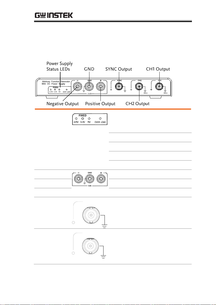
Front Panel
Power Supply
Status LEDs
Negative Output
GND
Positive Output
SYNC
CH1
These LEDs indicate the immediate
status of the power supply function
on the AFG-125P/225P:
2.5V
3.5V
5V
OVER LOAD
2.5V output is on
3.5V output is on
5V output is on
Overload condition
Negative output port
Ground port
Positive output port
Sync output. A TTL signal is output
as the sweep marker or sync output
signal.
1
CH1 (Signal 1) output.
50Ω
13
Page 14
AFG-200 SERIES USER MANUAL
C
H
CH2
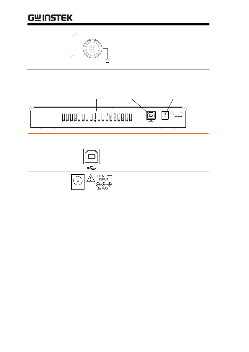
Rear Panel
Ven t
USB Device Port
Input Power
2
50Ω
Vent USB Device Port Input Power
Cooling vent.
CH1 (Signal 2) output
(AFG-225/AFG-225P only).
DC 5V
INPUT
2A MAX.
Interfaces with the GDS-2000A and
can also provide power.
Input power source:
DC 5V; 2A max.
14
Page 15
AFG-200 SERIES USER MANUAL
System Requirements
Operating System
Microsoft Windows XP
Microsoft Windows 7
Microsoft Windows Vista
CPU
Memory
Hard Disk Space
Supports
USB2.0(compatible
with USB1.1)
300MHz
256MB
100MB
The USB 2.0 Universal Serial Bus specification is
supported with transfer rates from USB1.1 to
USB2.0.
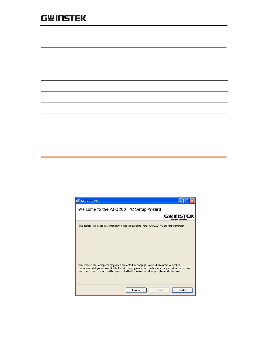
Software Installation
Close all the programs that are currently running.
Insert the included installation CD into your CD-ROM drive, and
execute the following steps:
1. Execute the installer on the CD. Install the software step by step
by following the prompts.
2. Connect hardware after the installation is completed. The
computer will automatically search for the new hardware and
install its driver. You can start to use the signal generator after
the driver is installed.
15
Page 16
AFG-200 SERIES USER MANUAL
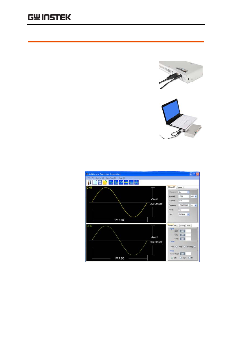
Setup the Signal Generator
PC
Communication
1. Plug the power adapter into
the power input port on the
rear panel.
2. Connect the type B end of
the accessory USB cable to
the USB B port on the signal
generator, and then connect
the type A end of the USB
cable to the USB A port on
the computer.
3. Turn on the PC and control the signal generator
through the PC software.
The signal generator is ready for use.
16
Page 17

AFG-200 SERIES USER MANUAL
Default Settings
The command *RST is used to restore the default
panel settings.
Output Settings
Modulation
(AM/FM/FSK/
PM/SUM)
Function Sine Wave
Frequency 1kHz
Amplitude 1.000 Vpp
Offset 0.00V dc
Output units Vpp
Output terminal 50Ω
Power OFF
Sync OFF
Carrier wave 1kHz sine wave
Modulation wave 100Hz sine wave
AM depth 100%
FM deviation 100Hz
*RST
Sweep
FSK hop frequency 100Hz
FSK frequency 10Hz
PM phase deviation 180˚
SUM amplitude 50%
Modem status Off
Start/Stop frequency 100Hz/1kHz
Sweep time 1s
Sweep type Linear
17
Page 18

AFG-200 SERIES USER MANUAL
Burst
System Settings
Sweep status Off
Burst frequency 1kHz
Ncycle 1
Burst period 10ms
Burst starting phase 0˚
Burst status Off
Power off signal On
Error queue Cleared
Memory settings No change
Output Off
18
Page 19

AFG-200 SERIES USER MANUAL
REMOTE INTERFACE
Establishing a Remote Connection ....................................19
Configure USB interface.......................................................19
Remote control terminal connection...................................20
Command Syntax .................................................................21
Establishing a Remote Connection
The AFG-200 supports USB remote connections
Configure USB interface
USB
configuration
PC side connector
AFG-200 series
side connector
Type B, slave
Speed
Panel Operation
1. Connect the USB cable to the
rear panel USB B (slave) port.
2. When the PC asks for the
USB driver, select
XXXXXXX.inf included in the
software package or
download the driver from the
GW website,
www.gwinstek.com
1.1/2.0 (full speed)
.
19
Page 20

AFG-200 SERIES USER MANUAL
Remote control terminal connection
Te rm i na l
application
Functionality
check
PC Software
Invoke the terminal application such as MTTTY
(Multi-Threaded TTY). For USB, set the COM port,
baud rate, stop bit, data bit, and parity
accordingly.
To check the COM port No, see the Device
Manager in the PC. For WinXP, Control panel →
System → Hardware tab.
Run this query command via the terminal.
*idn?
This should return the Manufacturer, Model
number, Serial number, and Firmware version in
the following format.
GW INSTEK, AFG-X25X, SN:XXXXXXXX,Vm.mm
Note: ^j or ^m can be used as the terminal
character when using a terminal program.
The proprietary PC software, downloadable from
GWInstek website, can be used for remote control.
20
Page 21
AFG-200 SERIES USER MANUAL
Command Syntax
Compatible
standard
• IEEE488.2, 1992 (fully compatible)
• SCPI, 1994 (partially compatible)
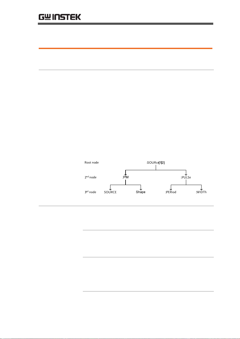
Command Tree
The SCPI standard is an ASCII based standard that
defines the command syntax and structure for
programmable instruments.
Commands are based on a hierarchical tree
structure. Each command keyword is a node on
the command tree with the first keyword as the
root node. Each sub node is separated with a
colon.
Shown below is a section of the SOURce[1|2]
root node and the :PM and :PULSe sub nodes.
Command types
Commands can be separated in to three distinc
types, simple commands, compound commands
and queries.
Simple
A single command with/without
a parameter
Example *OPC
Compound
Two or more commands
separated by a colon (:)
with/without a parameter
Example SOURce1:PULSe:WIDTh
21
Page 22
AFG-200 SERIES USER MANUAL
Query
A query is a simple or compound
command followed by a question
mark (?). A parameter (data) is
returned. The maximum or
minimum value for a parameter
can also be queried where
applicable.
Example
SOURce1:FREQuency?
SOURce1:FREQuency? MIN
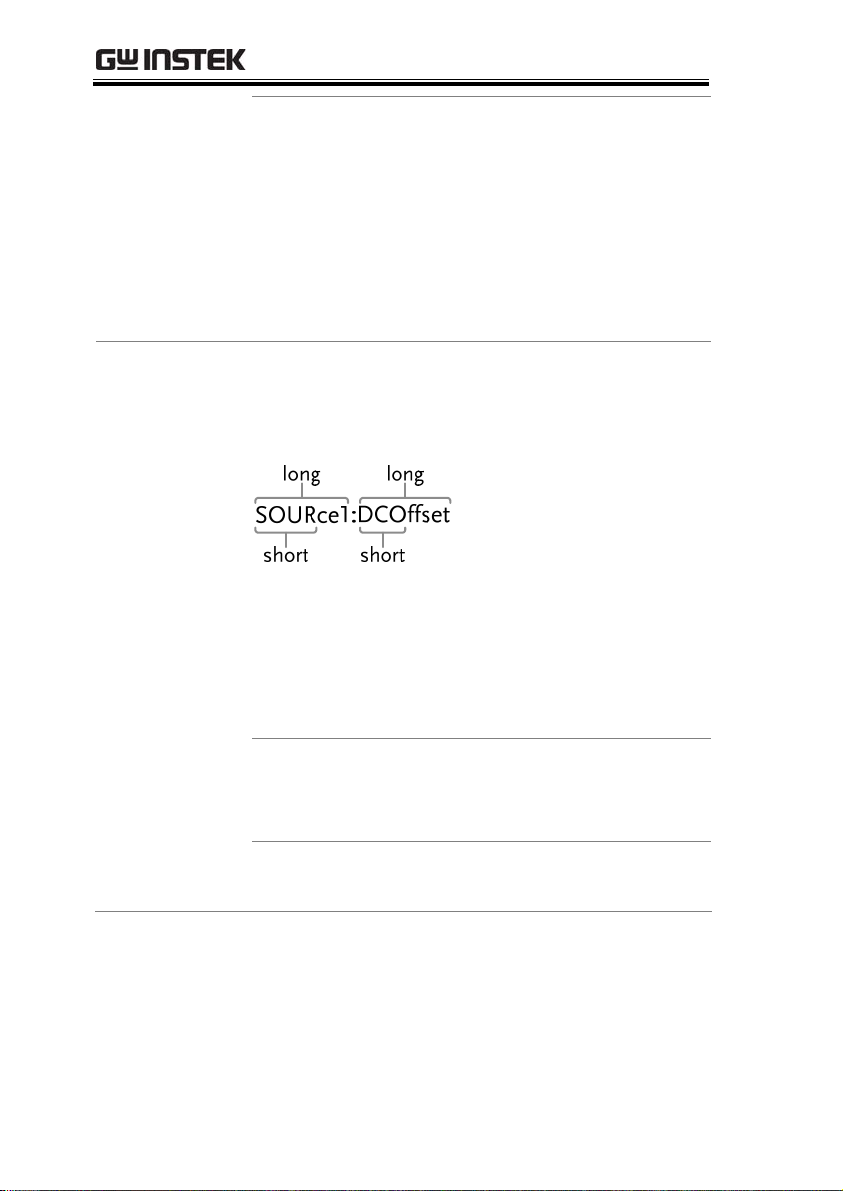
Command forms
Commands and queries have two different forms,
long and short. The command syntax is written
with the short form of the command in capitals
and the remainder (long form) in lower case.
The commands can be written in capitals or
lower-case, just so long as the short or long forms
are complete. An incomplete command will not be
recognized.
Below are examples of correctly written
commands:
LONG SOURce1:DCOffset
SOURCE1:DCOFFSET
source1:dcoffset
SHORT
SOUR1:DCO
sour1:dco
22
Page 23

AFG-200 SERIES USER MANUAL
Command
Format
1: command header
2: single space
3: parameter
4: message terminator
Square Brackets []
Commands that contain squares brackets indicate
that the contents are optional. The function of the
command is the same with or without the square
bracketed items. Brackets are not sent with the
command.
For example, the frequency query below can use any of
the following 3 forms:
SOURce1:FREQuency? [MINimum|MAXimum]
SOURce1:FREQuency? MAXimum
SOURce1:FREQuency? MINimum
SOURce1:FREQuency?
Braces {}
Commands that contain braces indicate one item
within the braces must be chosen. Braces are not
sent with the command.
Angled Brackets
<>
Angle brackets are used to indicate that a value
must be specified for the parameter. See the
parameter description below for details. Angled
brackets are not sent with the command.
Bars |
Bars are used to separate multiple parameter
choices in the command format.
Parameters Type Description Example
<Boolean>
<NR1>
<NR2>
<NR3>
<NRf>
Boolean logic 0, 1/ON,OFF
integers 0, 1, 2, 3
decimal numbers
0.1, 3.14, 8.5
floating point 4.5e-1, 8.25e+1
any of NR1, 2, 3 1, 1.5, 4.5e-1
23
Page 24

AFG-200 SERIES USER MANUAL
<NRf+>
<Numeric>
NRf type with a
suffix including
MINimum,
MAXimum or
DEFault
parameters.
<aard>
Arbitrary ASCII
characters.
<discrete>
Discrete ASCII
character
parameters
<frequency>
<peak deviation
in Hz>
<rate in Hz>
<amplitude>
NRf+ type
including
frequency unit
suffixes.
NRf+ type
including voltage
peak to peak.
<offset>
NRf+ type
including volt
unit suffixes.
1, 1.5, 4.5e-1
MAX, MIN,
IMM, MAN
1 KHZ, 1.0 HZ,
ΜHZ
VPP
V
<seconds>
NRf+ type
including time
unit suffixes.
<percent>
NRf type N/A
<depth in
percent>
Message
terminators
LF
EOI
Note
LF CR
line feed code (new line) and
carriage return.
line feed code (new line)
IEEE-488 EOI (End-Or-Identify)
^j or ^m should be used when using a terminal
program.
24
NS, S MS US
Page 25

AFG-200 SERIES USER MANUAL
Command
Separators
Semicolon (;)
Colon +
Comma (,)
Space
Colon (:)
Semicolon (:;)
A space is used to separate a
parameter from a
keyword/command header.
A colon is used to separate
keywords on each node.
A semi colon is used to separate
subcommands that have the same
node level.
For example:
SOURce[1|2]:DCOffset?
SOURce[1|2]:OUTPut?
ÆSOURce1:DCOffset?;OUTPut?
A colon and semicolon can be
used to combine commands from
different node levels.
For example:
SOURce1:PM:SOURce?
SOURce:PULSe:WIDTh?
ÆSOURce1:PM:SOURce?:;SOURce:
PULSe:WIDTh?
When a command uses multiple
parameters, a comma is used to
separate the parameters.
For example:
SOURce:APPLy:SQUare 10KHZ, 2.0
VPP, -1V
25
Page 26

AFG-200 SERIES USER MANUAL
System Command
SYSTem:ERRor?
Description
Query Syntax SYSTem:ERRor?
Return parameter <string> Returns an error string,
Example SYSTem:ERRor?
Reads an error from the error queue. See page 122
for details regarding the error queue.
-138 Suffix not allowed
Returns an error string.
*IDN?
Description
Query Syntax *IDN?
Return parameter <string>
Example *IDN?
Returns the function generator manufacturer,
model number, serial number and firmware
version number in the following format:
GW INSTEK,AFG-X25X,SN:XXXXXXXX,Vm.mm
GW INSTEK,AFG-225,SN:XXXXXXXX,Vm.mm
System Query
<256 ASCII characters.
System Query
26
Returns the identification of the function
generator.
Page 27

AFG-200 SERIES USER MANUAL
*RST
Description
Reset the function generator to its factory default
System Command
state.
Note
Note the *RST command will not delete
instrument save states in memory.
Syntax *RST
SYSTem:VERSion?
Description
Performs a system version query. Returns a string
System Query
with the instrument, firmware version, FPGA
revision
Query Syntax SYSTem:VERSion?
Return parameter <string>
Example SYST:VERS?
AFG-225 VX.XXX_XXXX
*OPC
Description
Returns the year and version for that year (1).
System Command
This command sets the Operation Complete Bit
(bit 0) of the Standard Event Status Register after
the function generator has completed all pending
operations. For the AFG-200 series, the *OPC
command is used to indicate when a sweep or
burst has completed.
Note
Before the OPC bit is set, other commands may be
executed.
Syntax *OPC
27
Page 28

AFG-200 SERIES USER MANUAL
*OPC?
Description
Note
Query Syntax *OPC?
Return parameter 1
Example *OPC?
Returns the OPC bit to the output buffer when all
pending operations have completed. I.e. when the
OPC bit is set.
Commands cannot be executed until the *OPC?
query has completed.
1
Returns a “1” when all pending operations are
complete.
*WAI
Description
Note
This command waits until all pending operations
have completed before executing additional
commands. I.e., when the OPC bit is set.
This command is only used for triggered sweep
and burst modes.
System Query
System Command
Syntax *WAI
28
Page 29

AFG-200 SERIES USER MANUAL
Status Register Commands
*CLS
Description
Syntax *CLS
The *CLS command clears all the event registers,
the error queue and cancels an *OPC command.
*ESE
Description
Note
Syntax *ESE <enable value>
Parameter
Example *ESE 20
The Standard Event Status Enable command
determines which events in the Standard Event
Status Event register can set the Event Summary
Bit (ESB) of the Status Byte register. Any bit
positions set to 1 enable the corresponding event.
Any enabled events set bit 5 (ESB) of the Status
Byte register.
The *CLS command clears the event register, but
not the enable register.
<enable value> 0~255
Sets a bit weight of 20 (bits 2 and 4).
System Command
System Command
Query Syntax *ESE?
Return Parameter
Bit Register Bit Register
0 Not used 4 Message Available
1 Not used 5 Standard Event
2 Error Queue 6 Master Summary
3 Questionable
Data
7 Not used
29
Page 30

AFG-200 SERIES USER MANUAL
Example *ESE?
4
*ESR?
Description
Bit 2 is set.
System Command
Reads and clears the Standard Event Status
Register. The bit weight of the standard event
status register is returned.
Note
The *CLS will also clear the standard event status
register.
Query Syntax *ESR?
Return Parameter Bit Register Bit Register
0 Operation
4 Execution Error
Complete
1 Not Used 5 Command Error
2 Query Error 6 Not Used
3 Device Error 7 Power On
Query Example *ESR?
5
Returns the bit weight of the standard event status
register (bit 0 and 2).
*STB?
Description
Note
Syntax *STB?
30
Reads the Status byte condition register.
Bit 6, the master summary bit, is not cleared.
System Command
Page 31

AFG-200 SERIES USER MANUAL
*SRE
Description
Note
Syntax *SRE <enable value>
Parameter
Example *SRE 12
Query Syntax *SRE?
Return Parameter
Query Example *SRE?
The Service Request Enable Command determines
which events in the Status Byte Register are
allowed to set the MSS (Master summary bit). Any
bit that is set to “1” can cause the MSS bit to be set.
The *CLS command clears the status byte event
register, but not the enable register.
<enable value> 0~255
Sets a bit weight of 12 (bits 2 and 3) for the service
request enable register.
Bit Register Bit Register
0 Not used 4 Message Available
1 Not used 5 Standard Event
2 Error Queue 6 Master Summary
3 Questionable
Data
12
System Command
7 Not used
Returns the bit weight of the status byte enable
register.
31
Page 32

AFG-200 SERIES USER MANUAL
Apply Commands
The APPLy command has 5 different types of outputs (Sine, Square,
Ramp, Pulse, Noise, ). The command is the quickest, easiest way to
output waveforms remotely. Frequency, amplitude and offset can be
specified for each function.
As only basic parameters can be set with the Apply command, other
parameters use the instrument default values.
The Apply command will set the trigger source to immediate and
disable burst, modulation and sweep modes. Turns on the output
commandOUTPut[1|2] ON. The termination setting will not be
changed.
As the frequency, amplitude and offset parameters are in nested
square brackets, amplitude can only be specified if the frequency has
been specified and offset can only be specified if amplitude has been
set. For the example:
SOURce[1|2]:APPLy:SINusoid [<frequency> [,<amplitude>
[,<offset>] ]]
Output Frequency
32
For the output frequency, MINimum, MAXimum
and DEFault can be used. The default frequency
for all functions is set to 1 kHz. The maximum and
minimum frequency depends on the function
used. If a frequency output that is out of range is
specified, the max/min frequency will be used
instead. A “Data out range error will be
generated” from the remote terminal.
Page 33

AFG-200 SERIES USER MANUAL
Output
Amplitude
When setting the amplitude, MINimum,
MAXimum and DEFault can be used. The range
depends on the function being used and the output
termination (50Ω or high impedance). The default
amplitude for all functions is 100 mVpp (50Ω).
If the amplitude has been set and the output
termination is changed from 50Ω to high
impedance, the amplitude will double. Changing
the output termination from high impedance to
50Ω will half the amplitude.
Vrms, dBm or Vpp units can be used to specify the
output unit to use with the current command. The
VOLT:UNIT command can be used to set the units
when no unit is specified with the Apply
command. If the output termination is set to high
impedance, dBm units cannot be used. The units
will default to Vpp.
The output amplitude can be affected by the
function and unit chosen. Vpp and Vrms or dBm
values may have different maximum values due to
differences such as crest factor. For example, a
5Vrms square wave must be adjusted to 3.536
Vrms for a sine wave.
DC Offset voltage
The offset parameter can be set to MINimum,
MAXimum or DEFault. The default offset is 0
volts. The offset is limited by the output amplitude
as shown below.
|Voffset| < Vmax – Vpp/2
If the output specified is out of range, the
maximum offset will be set.
33
Page 34

AFG-200 SERIES USER MANUAL
The offset is also determined by the output
termination (50Ω or high impedance). If the offset
has been set and the output termination has
changed from 50Ω to high impedance, the offset
will double. Changing the output termination from
high impedance to 50Ω will half the offset.
SOURce[1|2]:APPLy:SINusoid
Description
Syntax
Parameter <frequency>
<amplitude>
Outputs a sine wave from the selected channel
when the command has executed. Frequency,
amplitude and offset can also be set.
SOURce[1|2]:APPLy:SINusoid [<frequency>
[,<amplitude> [,<offset>] ]]
Source Specific
Command
1μHz~25MHz
1mVpp~2.5Vpp (50Ω)
(0.883 Vrms)
<offset>
-1.25V~1.25V (50Ω)
Example SOUR1:APPL:SIN 2KHZ,MAX,MAX
Sets frequency to 2kHz and sets the amplitude and
offset to the maximum.
Source Specific
SOURce[1|2]:APPLy:SQUare
Description
Outputs a square wave from the selected channel
Command
when the command has executed. Frequency,
amplitude and offset can also be set. The duty
cycle is set to 50%.
Syntax
SOURce[1|2]:APPLy:SQUare [<frequency>
[,<amplitude> [,<offset>] ]]
Parameter <frequency>
<amplitude>
<offset>
1μHz~25MHz
1mVpp~2.5Vpp (50Ω)
-1.25V~1.25V (50Ω)
Example SOUR1:APPL:SQU 2KHZ,MAX,MAX
34
Page 35

AFG-200 SERIES USER MANUAL
Sets frequency to 2kHz and sets the amplitude and
offset to the maximum.
Source Specific
SOURce[1|2]:APPLy:RAMP
Description
Outputs a ramp wave from the selected channel
Command
when the command has executed. Frequency,
amplitude and offset can also be set. The
symmetry is set to 50%.
Syntax SOURce[1|2]:APPLy:RAMP [<frequency>
[,<amplitude> [,<offset>] ]]
Parameter <frequency>
<amplitude>
<offset>
1μHz~1MHz
1mVpp~2.5Vpp (50Ω)
-1.25V~1.25V (50Ω)
Example SOUR1:APPL:RAMP 2KHZ,MAX,MAX
Sets frequency to 2kHz and sets the amplitude and
offset to the maximum.
Source Specific
SOURce[1|2]:APPLy:PULSe
Description
Outputs a pulse waveform from the selected
Command
channel when the command has executed.
Frequency, amplitude and offset can also be set.
Note
The PW settings from the SOURce[1|2]:PULS:
WIDT command are preserved. Edge and pulse
width may be adjusted to supported levels.
Repetition rates will be approximated from the
frequency. For accurate repetition rates, the period
should be adjusted using the
SOURce[1|2]:PULS:PER command
Syntax SOUR[1|2]:APPLy:PULSe [<frequency> [,<amplitude>
[,<offset>] ]]
Parameter <frequency>
500μHz~25MHz
35
Page 36

AFG-200 SERIES USER MANUAL
<amplitude>
<offset>
1mVpp~2.5Vpp (50Ω)
-1.25V~1.25V (50Ω)
Example SOUR1:APPL:PULS 1KHZ,MIN,MAX
Sets frequency to 1kHz and sets the amplitude to
minimum and the and offset to the maximum.
Source Specific
SOURce[1|2]:APPLy:NOISe
Description
Outputs Gaussian noise. Amplitude and offset can
Command
also be set.
Note
Frequency cannot be used with the noise function;
however a value (or DEFault) must be specified.
The frequency is remembered for the next function
used.
Syntax SOURce[1|2]:APPLy:NOISe [<frequency|DEFault>
[,<amplitude> [,<offset>] ]]
Parameter <frequency> Not applicable
<amplitude>
<offset>
1mVpp~2.5Vpp (50Ω)
-1.25V~1.25V (50Ω)
Example SOUR1:APPL:NOIS DEF, 1, 1.0
Sets the amplitude to 1 volts with an offset of 1
volt.
SOURce[1|2]:APPLy:USER
Description
Note
36
Outputs an arbitrary waveform from the selected
channel. The output is that specified from the
FUNC:USER command.
Frequency and amplitude cannot be used with the
DC function; however a value (or DEFault) must
be specified. The values are remembered for the
next function used.
Source Specific
Command
Page 37

AFG-200 SERIES USER MANUAL
Syntax SOURce[1|2]:APPLy:USER [<frequency> [,<amplitude>
[,<offset>] ]]
Parameter <frequency>
<amplitude>
Example SOUR1:APPL:USER
<offset>
SOURce[1|2]:APPLy?
Description
Note
Syntax SOURce[1|2]:APPLy?
Return Parameter <string> Function, frequency,
Example SOUR1:APPL?
Outputs a string with the current settings.
The string can be passed back appended to the
Apply Command.
SIN +5.0000000000000E+03,+1.0000E+00,-1.0E+00
Returns a string with the current function and
parameters, Sine, 5kHz, 1 Vpp, -1V offset.
1μHz~60MHz
1mVpp~2.5Vpp (50Ω)
-1.25V~1.25V (50Ω)
Source Specific
Command
amplitude, offset
37
Page 38

AFG-200 SERIES USER MANUAL
Output Commands
Unlike the Apply commands, the Output commands are low level
commands to program the function generator.
This section describes the low-level commands used to program the
function generator. Although the APPLy command provides the
most straightforward method to program the function generator, the
low-level commands give you more flexibility to change individual
parameters.
Source Specific
SOURce[1|2]:FUNCtion
Description
The FUNCtion command selects and outputs the
selected output. The User parameter outputs an
arbitrary waveform previously set by the
SOURce[1|2]:FUNC:USER command.
Command
Note
38
If the function mode is changed and the current
frequency setting is not supported by the new
mode, the frequency setting will be altered to next
highest value.
Vpp and Vrms or dBm amplitude values may have
different maximum values due to differences such
as crest factor. For example, if a 5Vrms square
wave is changed to a sinewave, then the Vrms is
automatically adjusted to 3.536.
The modulation, burst and sweep modes can only
be used with some of the basic waveforms. If a
mode is not supported, the conflicting mode will
be disabled. See the table below.
Page 39

AFG-200 SERIES USER MANUAL
AM
FM
PM
FSK
SUM
SWEEP
BURST
Sine Square Ramp Pulse Noise ARB
9 9 9 9
9 9 9
9 9 9
× × ×
× × ×
9 9 9 9
×
× ×
9 9 9 9 9
9 9 9
9 9 9
× × ×
× ×
9
×
√
Syntax SOURce[1|2]:FUNCtion {SINusoid|SQUare|RAMP|
PULSe|NOISe| USER}
Example SOUR1:FUNC SIN
Sets the output as a sine function.
Query Syntax SOURce[1|2]:FUNCtion?
Return Parameter SIN, SQU, RAMP, PULS,
NOIS, USER
Returns the current output
type.
Example SOUR1:FUNC?
SIN
Current output is sine.
Source Specific
SOURce[1|2]:FREQuency
Description
The SOURce[1|2]:FREQuency command sets the
Command
output freuquency for the selected channel. The
query command returns the current frequency
setting.
Note
The maximum and minimum frequency depends
on the function mode.
Sine, Square
Ramp
Pulse
1μHz~25MHz
1μHz~1MHz
500μHz~25MHz
39
Page 40

AFG-200 SERIES USER MANUAL
Noise
User
If the function mode is changed and the current
frequency setting is not supported by the new
mode, the frequency setting will be altered to next
highest value.
The duty cycle of square waveforms depends on the
frequency settings.
1.0% to 99.0%(frequency≤100 KHz)
10% to 90% (100 KHz ≤ frequency ≤1MHz)
50% (frequency ≤ 25 MHz)
If the frequency is changed and the set duty cycle
cannot support the new frequency, the highest
duty cycle available at that frequency will be used.
A “settings conflict” error will result from the
above scenario.
Syntax SOURce[1|2]:FREQuency
{<frequency>|MINimum|MAXimum}
Example SOUR1:FREQ MAX
Sets the frequency to the maximum for the current
mode.
Not applicable
1μHz~60MHz
Query Syntax SOURce[1|2]:FREQuency?
Return Parameter <NR3> Returns the frequency for
the current mode.
Example SOUR1:FREQ? MAX
+1.0000000000000E+06
The maximum frequency that can be set for the
current function is 1MHz.
40
Page 41

AFG-200 SERIES USER MANUAL
SOURce[1|2]:AMPlitude
Description
The SOURce[1|2]:AMPLitude command sets the
output amplitude for the selected channel. The
query command returns the current amplitude
settings.
Source Specific
Command
Note
The maximum and minimum amplitude depends
on the output termination. The default amplitude
for all functions is 100 mVpp (50Ω). If the
amplitude has been set and the output termination
is changed from 50Ω to high impedance, the
amplitude will double. Changing the output
termination from high impedance to 50Ω will half
the amplitude.
The offset and amplitude are related by the
following equation.
|Voffset| < Vmax – Vpp/2
If the output termination is set to high impedance,
dBm units cannot be used. The units will default to
Vpp.
The output amplitude can be affected by the
function and unit chosen. Vpp and Vrms or dBm
values may have different maximum values due to
differences such as crest factor. For example, a
5Vrms square wave must be adjusted to 3.536
Vrms for a sine wave.
The amplitude units can be explicitly used each
time the SOURce[1|2]:AMPlitude command is
used. Alternatively, the VOLT:UNIT command can
be used to set the amplitude units for all
commands.
41
Page 42

AFG-200 SERIES USER MANUAL
Syntax SOURce[1|2]:AMPlitude {< amplitude>
|MINimum|MAXimum}
Example SOUR1:AMP MAX
Sets the amplitude to the maximum for the current
mode.
Query Syntax SOURce[1|2]:AMPlitude? {MINimum|MAXimum}
Return Parameter <NR3> Returns the amplitude for
the current mode.
Example SOUR1:AMP? MAX
+2.50000E+00
The maximum amplitude that can be set for the
current function is 2.5 volts.
Source Specific
SOURce[1|2]:DCOffset
Description
Sets or queries the DC offset for the current mode.
Command
Note
The offset parameter can be set to MINimum,
MAXimum or DEFault. The default offset is 0
volts. The offset is limited by the output amplitude
as shown below.
|Voffset| < Vmax – Vpp/2
If the output specified is out of range, the
maximum offset will be set.
The offset is also determined by the output
termination (50Ω or high impedance). If the offset
has been set and the output termination has
changed from 50Ω to high impedance, the offset
will double. Changing the output termination from
high impedance to 50Ω will half the offset.
42
Page 43

AFG-200 SERIES USER MANUAL
Syntax SOURce[1|2]:DCOffset {< offset>
|MINimum|MAXimum}
Example SOUR1:DCO MAX
Sets the offset to the maximum for the current
mode.
Query Syntax SOURce[1|2]:DCOffset? {MINimum|MAXimum}
Return Parameter <NR3> Returns the offset for the
current mode.
Example SOUR1:DCO?
+1.0000E+00
The offset for the current mode is set to +1 volts.
Source Specific
SOURce[1|2]:SQUare:DCYCle
Description
Sets or queries the duty cycle for square waves
Command
only. The setting is remembered if the function
mode is changed. The default duty cycle is 50%.
Note The duty cycle of square waveforms depend on the
frequency settings.
1.0% to 99.0%(frequency≤100 KHz)
10% to 90% (100 KHz ≤ frequency ≤1MHz)
50% (frequency ≤ 25 MHz)
If the frequency is changed and the set duty cycle
cannot support the new frequency, the highest
duty cycle available at that frequency will be used.
A “settings conflict” error will result from the
above scenario.
For square waveforms, the Apply command and
AM/FM modulation modes ignore the duty cycle
settings.
Syntax SOURce[1|2]:SQUare:DCYCle {< percent>
|MINimum|MAXimum}
43
Page 44

AFG-200 SERIES USER MANUAL
Example SOUR1:SQU:DCYC MAX
Sets the duty cycle to the highest possible for the
current frequency.
Query Syntax SOURce[1|2]:SQUare:DCYCle?
{MINimum|MAXimum}
Return Parameter <NR3> Returns the duty cycle as a
percentage.
Example SOUR1:SQU:DCYC?
+5.00E+01
The duty cycle is set 50%.
Source Specific
SOURce[1|2]:RAMP:SYMMetry
Description
Sets or queries the symmetry for ramp waves only.
Command
The setting is remembered if the function mode is
changed. The default symmetry is 50%.
Note
For ramp waveforms, the Apply command and
AM/FM modulation modes ignore the current
symmetry settings.
Syntax SOURce[1|2]:RAMP:SYMMetry {< percent>
|MINimum|MAXimum}
Example SOUR1:RAMP:SYMM MAX
Sets the symmetry to the 100%.
Query Syntax SOURce[1|2]:RAMP:SYMMetry?
{MINimum|MAXimum}
Return Parameter <NR3> Returns the symmetry as a
percentage.
Example SOUR1:RAMP:SYMMetry?
44
+1.0000E+02
The symmetry is set as 100%.
Page 45

OUTPut[1|2]
Description
AFG-200 SERIES USER MANUAL
Source Specific
Command
Enables/Disables or queries the front panel output
from the selected channel. The default is set to off.
Note
If the output is overloaded by an external voltage,
the output will turn off and an error message will
be displayed. The overload must first be removed
before the output can be turned on again with
output command.
Using the Apply command automatically sets the
front panel output to on.
Syntax OUTPut[1|2] {OFF|ON}
Example OUTP1 ON
Turns the channel 1 output on.
Query Syntax OUTPut[1|2]?
Return Parameter 1
0
Example OUTP1?
1
The channel 1 output is currently on.
OUTPut[1|2]:LOAD
Description
Sets or queries the output termination. Two
impedance settings can be chosen, DEFault (50Ω)
and INFinity (high impedance >10 kΩ).
The output termination is to be used as a reference
only. If the output termination is set 50Ω but the
actual load impedance is not 50Ω, then the
amplitude and offset will not be correct.
ON
OFF
Source Specific
Command
Note
If the amplitude has been set and the output
termination is changed from 50Ω to high
45
Page 46

AFG-200 SERIES USER MANUAL
impedance, the amplitude will double. Changing
the output termination from high impedance to
50Ω will half the amplitude.
If the output termination is set to high impedance,
dBm units cannot be used. The units will default to
Vpp.
Syntax OUTPut[1|2]:LOAD {DEFault|INFinity}
Example OUTP1:LOAD DEF
Sets the channel 1 output termination to 50Ω.
Query Syntax OUTPut[1|2]:LOAD?
Return Parameter DEF Default
INF INFinity
Example OUTP1:LOAD?
DEF
The output termination for channel 1 is set to 50Ω.
Source Specific
SOURce[1|2]:VOLTage:UNIT
Description
Sets or queries the output amplitude units. There
Command
are three types of units: VPP, VRMS and DBM.
Note
The units set with the VOLTage:UNIT command
will be used as the default unit for all amplitude
units unless a different unit is specifically used for
a command.
If the output termination is set to high impedance,
dBm units cannot be used. The Units will
automatically default to Vpp.
Syntax SOURce[1|2]:VOLTage:UNIT {VPP|VRMS|DBM}
Example SOUR1:VOLT:UNIT VPP
Sets the amplitude units to Vpp.
Query Syntax SOURce[1|2]:VOLTage:UNIT?
Return Parameter VPP Vpp
46
Page 47

AFG-200 SERIES USER MANUAL
VRMS Vrms
Example
DBM dBm
SOUR1:VOLT:UNIT?
VPP
The amplitude units are set to Vpp.
47
Page 48

AFG-200 SERIES USER MANUAL
Pulse Configuration Commands
The pulse chapter is used to control and output pulse waveforms.
Unlike the APPLy command, low level control is possible including
setting the rise time, fall time, period and pulse width.
Period
90%
90%
50%
10%
Fall timeRise time
10%
50%
Pulse Width
SOURce[1|2]:PULSe:PERiod
Description
Note
Syntax SOURce[1|2]:PULSe:PERiod
Sets or queries the pulse period. The default period
is 1 ms.
The pulse period must be greater than the pulse
width and edge time(1.6x) combined.
Pulse Width + (1.6 * Edge Time) < Period
If the edge time or pulse width are too great, they
will automatically be reduced to fit the period by
the function generator.
The PULSe:PERiod function will change the period
for all functions, not just for the pulse waveforms.
If a different function is chosen and the current
period is out of range, the period will be
automatically adjusted to suit the new function.
{<seconds>|MINimum|MAXimum}
Source Specific
Command
Example SOUR1:PULS:PER MIN
Sets the period to the minimum time allowed.
Query Syntax SOURce[1|2]:PULSe:PERiod? [MINimum|MAXimum]
48
Page 49

AFG-200 SERIES USER MANUAL
Return Parameter <seconds> 40ns~2000s
Example SOUR1:PULS:PER?
+1.0000E+01
The period is set to 10 seconds.
SOURce[1|2]:PULSe:WIDTh
Description
Note
Syntax SOURce[1|2]:PULSe:WIDTh
Sets or queries the pulse width. The default pulse
width is 100us.
The minimum pulse width is affected by the
period time. If the period is over 20 or 200 seconds,
then the minimum pulse width is 1us and 10us,
respectively.
Pulse width is defined as the time from the rising
to falling edges (at a threshold of 50%).
The pulse width cannot be less than the edge time
times 1.6.
Pulse Width > 1.6 * Edge Time
The pulse width must be less than the period
minus the edge time (x1.6).
Pulse Width < Period – (1.6 *Edge Time)
{<seconds>|MINimum|MAXimum}
Source Specific
Command
Example SOUR1:PULS:WIDT MAX
Sets the pulse width to the maximum allowed.
Query Syntax SOURce[1|2]:PULSe:WIDTh? [MINimum|MAXimum]
Return Parameter <seconds> 20 ns ~ 1999.9 seconds
Example SOUR1:PULS:WIDT? MIN
+8.0000E-09
The pulse width is set to 8 nanoseconds.
49
Page 50

AFG-200 SERIES USER MANUAL
Amplitude Modulation (AM) Commands
AM Overview
To successfully create an AM waveform, the following commands
must be executed in order.
Enable AM
Modulation
Configure Carrier
Select
Modulation
Source
Select Shape
Set Modulating
Frequency
Set Modulation
Depth
3. Turn on AM modulation using the
SOURce[1|2]: AM:STAT ON command
4. Use the APPLy command to select a carrier
waveform. Alternatively the equivalent FUNC,
FREQ, AMPl, and DCOffs commands can be
used to create a carrier waveform with a
designated frequency, amplitude and offset.
5. Select an internal or external modulation source
using the SOURce[1|2]:AM:SOUR command.
6. Use the SOURce[1|2]:AM:INT:FUNC
command to select a sine, square, upramp,
dnramp or triangle modulating waveshape. For
internal sources only.
7. Set the modulating frequency using the
SOURce[1|2]: AM:INT:FREQ command. For
internal sources only.
8. Set the modulation depth using the
SOURce[1|2]: AM:DEPT command.
50
Page 51

AFG-200 SERIES USER MANUAL
SOURce[1|2]:AM:STATe
Description
Sets or disables AM modulation. By default AM
modulation is disabled. AM modulation must be
enabled before setting other parameters.
Source Specific
Command
Note
Burst or sweep mode will be disabled if AM
modulation is enabled. As only one modulation is
allowed at any one time, other modulation modes
will be disabled when AM modulation is enabled.
Syntax SOURce[1|2]:AM:STATe {OFF|ON}
Example SOUR1:AM:STAT ON
Enables AM modulation.
Query Syntax SOURce[1|2]:AM:STATe?
Return Parameter
0 Disabled (OFF)
1 Enabled (ON)
Example SOUR1:AM:STAT?
1
AM modulation mode is currently enabled.
Source Specific
SOURce[1|2]:AM:INTernal:FUNCtion
Description
Sets the shape of the modulating waveform from
Command
sine, square, triangle, upramp and dnramp. The
default shape is sine.
Note
Square and triangle waveforms have a 50% duty
cycle. Upramp and dnramp have a symmetry of
100% and 0%, respectively.
Syntax SOURce[1|2]:AM:INTernal:FUNCtion
{SINusoid|SQUare|TRIangle|UPRamp|DNRamp}
Example SOUR1:AM:INT:FUNC SIN
Sets the AM modulating wave shape to sine.
51
Page 52

AFG-200 SERIES USER MANUAL
Query Syntax SOURce[1|2]:AM:INTernal:FUNCtion?
Return Parameter
SIN Sine UPRAMP Upramp
SQU Square DNRAMP Dnramp
TRI Triangle
Example SOUR1:AM:INT:FUNC?
SIN
The shape for the modulating waveform is Sine.
Source Specific
SOURce[1|2]:AM:INTernal:FREQuency
Description
Sets the frequency of the internal modulating
Command
waveform only. The default frequency is 100Hz.
Syntax SOURce[1|2]:AM:INTernal:FREQuency
{<frequency>|MINimum|MAXimum}
Parameter <frequency> 2 mHz~ 20 kHz
Example SOUR1:AM:INT:FREQ +1.0000E+02
Sets the modulating frequency to 100Hz.
Query Syntax SOURce[1|2]:AM:INTernal:FREQuency?
[MINimum|MAXimum]
Return Parameter
<NR3> Returns the frequency in
Hz.
Example SOUR1:AM:INT:FREQ? MIN
+1.0000E+02
Returns the minimum frequency allowed.
SOURce[1|2]:AM:DEPTh
Description
52
Sets or queries the modulation depth for internal
sources only. The default is 100%.
Source Specific
Command
Page 53

AFG-200 SERIES USER MANUAL
Note
Syntax SOURce[1|2]:AM:DEPTh {<depth in percent>
Parameter <depth in percent> 0~120%
Example SOUR1:AM:DEPT 50
Query Syntax SOURce[1|2]:AM:DEPTh? [MINimum|MAXimum]
Return Parameter
Example SOUR1:AM:DEPT?
The function generator will not output more than
±5V, regardless of the modulation depth.
The modulation depth of an external source is
controlled using the ±5V MOD INPUT terminal on
the rear panel, and not the
SOURce[1|2]:AM:DEPTh command.
|MINimum|MAXimum}
Sets the modulation depth to 50%.
<NR3> Return the modulation
depth as a percentage.
+1.0000E+02
The modulation depth is 100%.
53
Page 54

AFG-200 SERIES USER MANUAL
Frequency Modulation (FM) Commands
FM Overview
The following is an overview of the steps required to generate an
FM waveform.
Enable FM
Modulation
Configure Carrier
Select
Modulation
Source
Select shape
Set Modulating
Frequency
Set Peak
Frequency
Deviation
9. Turn on FM modulation using the
SOURce[1|2]: FM:STAT ON command.
10. Use the APPLy command to select a carrier
waveform. Alternatively, the FUNC, FREQ,
AMPl, and DCOffs commands can be used to
create a carrier waveform with a designated
frequency, amplitude and offset.
11. Select an internal or external modulation source
using the SOURce[1|2]:FM:SOUR command.
12. Use the SOURce[1|2]:FM:INT:FUNC command
to select a sine, square, upramp, dnramp or
triangle modulating waveshape. For internal
sources only.
13. Set the modulating frequency using the
SOURce[1|2]: FM:INT:FREQ command. For
internal sources only.
14. Use the SOURce[1|2]:FM:DEV command to set
the frequency deviation.
54
Page 55

AFG-200 SERIES USER MANUAL
SOURce[1|2]:FM:STATe
Description
Sets or disables FM modulation. By default FM
modulation is disabled. FM modulation must be
enabled before setting other parameters.
Source Specific
Command
Note
Burst or sweep mode will be disabled if FM
modulation is enabled. As only one modulation is
allowed at any one time, other modulation modes
will be disabled when FM modulation is enabled.
Syntax SOUR[1|2]:FM:STATe {OFF|ON}
Example SOUR1:FM:STAT ON
Enables FM modulation.
Query Syntax SOURce[1|2]:FM:STATe?
Return Parameter
0 Disabled (OFF)
1 Enabled (ON)
Example SOUR1:FM:STAT?
1
FM modulation mode is currently enabled.
Source Specific
SOURce[1|2]:FM:INTernal:FUNCtion
Description
Sets the shape of the modulating waveform from
Command
sine, square, triangle, upramp and dnramp. The
default shape is sine.
Note
Square and triangle waveforms have a 50% duty
cycle. Upramp and dnramp have a symmetry of
100% and 0%, respectively.
Syntax SOURce[1|2]:FM:INTernal:FUNCtion
{SINusoid|SQUare|TRIangle|UPRamp|DNRamp}
Example SOUR1:FM:INT:FUNC SIN
Sets the FM modulating wave shape to sine.
55
Page 56

AFG-200 SERIES USER MANUAL
Query Syntax SOURce[1|2]:FM:INTernal:FUNCtion?
Return Parameter
SIN Sine UPRAMP Upramp
SQU Square DNRAMP Dnramp
TRI Triangle
Example SOUR1:FM:INT:FUNC?
SIN
The shape for the modulating waveform is Sine.
Source Specific
SOURce[1|2]:FM:INTernal:FREQuency
Description
Sets the frequency of the internal modulating
Command
waveform only. The default frequency is 10Hz.
Syntax SOURce[1|2]:FM:INTernal:FREQuency
{<frequency>|MINimum|MAXimum}
Parameter <frequency> 2 mHz~ 20 kHz
Example SOUR1:FM:INT:FREQ 100
Sets the modulating frequency to 100Hz.
Query Syntax SOURce[1|2]:FM:INTernal:FREQuency?
[MINimum|MAXimum]
Return Parameter
<NR3> Returns the frequency in
Hz.
Example SOUR1:FM:INT:FREQ? MAX
+2.0000E+04
Returns the maximum frequency allowed.
SOURce[1|2]:FM:DEViation
56
Source Specific
Command
Page 57

AFG-200 SERIES USER MANUAL
Description
Note
Sets or queries the peak frequency deviation of the
modulating waveform from the carrier waveform.
The default peak deviation is 100Hz.
The frequency deviation of external sources is
controlled using the ±5V MOD INPUT terminal on
the rear panel. A positive signal (>0~+5V) will
increase the deviation (up to the set frequency
deviation), whilst a negative voltage will reduce
the deviation.
The relationship of peak deviation to modulating
frequency and carrier frequency is shown below.
Peak deviation = modulating frequency – carrier
frequency.
The carrier frequency must be greater than or
equal to the peak deviation frequency. The sum of
the deviation and carrier frequency must not
exceed the maximum frequency for a specific
carrier shape. If an out of range deviation is set for
any of the above conditions, the deviation will be
automatically adjusted to the maximum value
allowed and an “out of range” error will be
generated.
For square wave carrier waveforms, the deviation
may cause the duty cycle frequency boundary to
be exceeded. In these conditions the duty cycle will
be adjusted to the maximum allowed and a
“settings conflict” error will be generated.
Syntax SOURce[1|2]:FM:DEViation {<peak deviation in
Hz>|MINimum|MAXimum}
Parameter <peak deviation in Hz> DC~25MHz
DC~15MHz(square)
DC~1MHz (Ramp)
Example SOUR1:FM:DEV MAX
Sets the frequency deviation to the maximum
value allowed.
57
Page 58

AFG-200 SERIES USER MANUAL
Query Syntax SOURce[1|2]:FM:DEViation? [MINimum|MAXimum]
Return Parameter
Example SOURce[1|2]:FM:DEViation? MAX
<NR3> Returns the frequency
deviation in Hz.
+1.0000E+01
Returns the maximum frequency deviation
allowed.
58
Page 59

AFG-200 SERIES USER MANUAL
Frequency-Shift Keying (FSK) Commands
FSK Overview
The following is an overview of the steps required to generate an
FSK modulated waveform.
Enable FSK
Modulation
Configure Carrier
Select FSK Source
Select FSK HOP
Frequency
Set FSK Rate
15. Turn on FSK modulation using the
SOURce[1|2]: FSK:STAT ON command.
16. Use the APPLy command to select a carrier
waveform. Alternatively, the FUNC, FREQ,
AMPl, and DCOffs commands can be used to
create a carrier waveform with a designated
frequency, amplitude and offset.
17. Select an internal or external modulation source
using the SOURce[1|2]:FSK:SOUR command.
18. Set the hop frequency using the
SOURce[1|2]:FSK:FREQ command.
19. Use the SOURce[1|2]: FSK:INT:RATE
command to set the FSK rate. The FSK rate can
only be set for internal sources.
SOURce[1|2]:FSKey:STATe
Description
Turns FSK Modulation on or off. By default FSK
modulation is off.
Source Specific
Command
Note
Syntax SOURce[1|2]:FSKey:STATe {OFF|ON}
Burst or sweep mode will be disabled if FSK
modulation is enabled. As only one modulation is
allowed at any one time, other modulation modes
will be disabled when FSK modulation is enabled.
59
Page 60

AFG-200 SERIES USER MANUAL
Example SOUR1:FSK:STAT ON
Enables FSK modulation
Query Syntax SOURce[1|2]:FSKey:STATe?
Return Parameter
0 Disabled (OFF)
1 Enabled (ON)
Example SOUR1:FSK:STAT?
1
FSK modulation is currently enabled.
Source Specific
SOURce[1|2]:FSKey:FREQuency
Description
Sets the FSK hop frequency. The default hop
Command
frequency is set to 100Hz.
Note
For FSK, the modulating waveform is a square
wave with a duty cycle of 50%.
Syntax SOURce[1|2]:FSKey:FREQuency
{<frequency>|MINimum|MAXimum}
Parameter <frequency>
1 μHz~25MHz(sine)
1 μHz~15MHz(Square、
Pulse)
1 μHz~1MHz(Ramp)
Example SOUR1:FSK:FREQ +1.0000E+02
Sets the FSK hop frequency to to 100Hz.
Query Syntax SOURce[1|2]:FSKey:FREQuency?
[MINimum|MAXimum]
Return Parameter
<NR3> Returns the frequency in
Hz.
Example SOUR1:FSK:FREQ? MAX
+2.5000E+06
60
Returns the maximum hop frequency allowed.
Page 61

AFG-200 SERIES USER MANUAL
SOURce[1|2]:FSKey:INTernal:RATE
Description
Sets or queries the FSK rate for internal sources
only.
Source Specific
Command
Note
External sources will ignore this command.
Syntax SOURce[1|2]:FSKey:INTernal:RATE {<rate in Hz>
|MINimum|MAXimum}
Parameter <rate in Hz> 2 mHz~100 kHz
Example SOUR1:FSK:INT:RATE MAX
Sets the rate to the maximum (100kHz).
Query Syntax SOURce[1|2]:FSKey:INTernal:RATE?
[MINimum|MAXimum]
Return Parameter
<NR3> Returns the FSK rate in
Hz.
Example SOUR1:FSK:INT:RATE? MAX
+1.0000E+05
Returns the maximum FSK rate allowed.
61
Page 62

AFG-200 SERIES USER MANUAL
Phase Modulation (PM)Commands
PM Overview
The following is an overview of the steps required to generate a PM
modulated waveform.
Enable PM
Modulation
Configure Carrier
Select
Modulation
Source
Select Shape
Select
Modulating
Frequency
Set DEViation
20. Turn on PM modulation using the
SOURce[1|2]: PM:STATe ON command.
21. Use the APPLy command to select a carrier
waveform. Alternatively, the FUNC, FREQ,
AMPl, and DCOffs commands can be used to
create a carrier waveform with a designated
frequency, amplitude and offset.
22. Select an internal or external modulation source
using the SOURce[1|2]:PM:SOUR command.
23. Use the SOURce[1|2]: PM:INT:FUNC
command to select a sine, square, upramp,
dnramp or triangle modulating waveshape. For
internal sources only.
24. Set the modulating frequency using the
SOURce[1|2]:PM:INT:FREQ command. For
internal sources only.
25. Use the SOURce[1|2]:PM:DEV command to set
the phase DEViation.
62
Page 63

AFG-200 SERIES USER MANUAL
SOURce[1|2]:PM:STATe
Description
Turns PM Modulation on or off. By default PM
modulation is off.
Source Specific
Command
Note
Burst or sweep mode will be disabled if PM
modulation is enabled. As only one modulation is
allowed at any one time, other modulation modes
will be disabled when PM
modulation is enabled.
Syntax SOURce[1|2]:PM:STATe {OFF|ON}
Example SOUR1:PM:STAT ON
Enables PM modulation
Query Syntax SOURce[1|2]:PM:STATe?
Return Parameter
0 Disabled (OFF)
1 Enabled (ON)
Example SOUR1:PM:STAT?
1
PM modulation is currently enabled.
Source Specific
SOURce[1|2]:PM:INTernal:FUNction
Description
Sets the shape of the modulating waveform from
Command
sine, square, triangle, upramp and dnramp. The
default shape is sine.
Note
Square and triangle waveforms have a 50% duty
cycle. Upramp and dnramp have a symmetry to
100% and 0%, respectively. .
Syntax SOURce[1|2]:PM:INTernal:FUNction
{SINusoid|SQUare|TRIangle|UPRamp|DNRamp}
Example SOUR1:PM:INT:FUN SIN
Sets the PM modulating wave shape to sine. .
Query Syntax SOURce[1|2]:PM:INTernal:FUNction?
63
Page 64

AFG-200 SERIES USER MANUAL
Return Parameter
SIN Sine UPRAMP Upramp
SQU Square DNRAMP Dnramp
TRI Triangle
Example SOUR1:PM:INT:FUNC?
SIN
The shape for the modulating waveform is Sine.
Source Specific
SOURce[1|2]:PM:INTernal:FREQuency
Description
Sets the modulating waveform frequency for
Command
internal sources. The default frequency is set to
100Hz.
Syntax SOURce[1|2]:PM:INTernal:FREQuency
{<frequency>|MINimum|MAXimum}
Parameter <frequency> 2 mHz~ 20 kHz
Example SOUR1:PM:INT:FREQ MAX
Sets the frequency to the maximum value.
Query Syntax SOURce[1|2]:PM:INTernal:FREQuency?
Return Parameter
<NR3> Returns the frequency in
Hz.
Example SOUR1:PM:INT:FREQ? MAX
+2.0000E+04
Returns the modulating frequency. (20kHz)
SOURce[1|2]:PM:DEViation
Description
64
Sets or queries the phase deviation of the
modulating waveform from the carrier waveform.
The default phase deviation is 180°.
Source Specific
Command
Page 65

AFG-200 SERIES USER MANUAL
Note
For external sources, the phase deviation is
controlled by the ±5V MOD Input terminal on the
rear panel. If the phase deviation is set to 180
degrees, then +5V represents a deviation of 180
degrees. A lower input voltage will decrease the
set phase deviation.
Syntax SOURce[1|2]:PM:DEViation {< phase>|minimum
|maximum}
Parameter <percent> 0°~360°
Example SOUR1:PM:DEViation +3.0000E+01
Sets the deviation to 30°.
Query Syntax SOURce[1|2]:PM:DEViation?
Return Parameter
<NR3> Returns the deviation .
Example SOUR1:PM:DEViation?
+3.0000E+01
The current deviation is 30°.
65
Page 66

AFG-200 SERIES USER MANUAL
SUM Modulation (SUM) Commands
SUM Overview
The following is an overview of the steps required to generate a
SUM modulated waveform.
Enable SUM
Modulation
Configure Carrier
Select
Modulation
Source
Select Shape
Select
Modulating
Frequency
Set AMPL
26. Turn on SUM modulation using the
SOURce[1|2]: SUM:STATe ON command.
27. Use the APPLy command to select a carrier
waveform. Alternatively, the FUNC, FREQ,
AMPl, and DCOffs commands can be used to
create a carrier waveform with a designated
frequency, amplitude and offset.
28. Select an internal or external modulation source
using the SOURce[1|2]:SUM:SOUR command.
29. Use the SOURce[1|2]: SUM:INT:FUNC
command to select a sine, square, upramp,
dnramp or triangle modulating waveshape. For
internal sources only.
30. Set the modulating frequency using the
SOURce[1|2]:SUM:INT:FREQ command. For
internal sources only.
31. Use the SOURce[1|2]:SUM:AMPL command to
set the modulating amplitude.
66
Page 67

AFG-200 SERIES USER MANUAL
SOURce[1|2]:SUM:STATe
Description
Turns SUM Modulation on or off. By default SUM
modulation is off.
Source Specific
Command
Note
Burst or sweep mode will be disabled if SUM
modulation is enabled. As only one modulation is
allowed at any one time, other modulation modes
will be disabled when SUM modulation is
enabled.
Syntax SOURce[1|2]:SUM:STATe {OFF|ON}
Example SOUR1:SUM:STAT ON
Enables SUM modulation
Query Syntax SOURce[1|2]:SUM:STATe?
Return Parameter
0 Disabled (OFF)
1 Enabled (ON)
Example SOUR1:SUM:STAT?
ON
SUM modulation is currently enabled.
Source Specific
SOURce[1|2]:SUM:INTernal:FUNction
Description
Sets the shape of the modulating waveform from
Command
sine, square, triangle, upramp and dnramp. The
default shape is sine.
Note
Square and triangle waveforms have a 50% duty
cycle. Upramp and dnramp have a symmetry to
100% and 0%, respectively. .
Syntax SOURce[1|2]:SUM:INTernal:FUNction
{SINusoid|SQUare|TRIangle|UPRamp|DNRamp}
Example SOUR1:SUM:INT:FUN SIN
Sets the SUM modulating wave shape to sine.
67
Page 68

AFG-200 SERIES USER MANUAL
Query Syntax SOURce[1|2]:SUM:INTernal:FUNction?
Return Parameter
SIN Sine UPRAMP Upramp
SQU Square DNRAMP Dnramp
TRI Triangle
Example SOUR1:SUM:INT:FUNC?
SIN
The shape for the modulating waveform is Sine.
Source Specific
SOURce[1|2]:SUM:INTernal:FREQuency
Description
Sets the modulating waveform frequency for
Command
internal sources. The default frequency is set to
100Hz.
Syntax SOURce[1|2]:SUM:INTernal:FREQuency
{<frequency>|MINimum|MAXimum}
Parameter <frequency> 2 mHz~ 20 kHz
Example SOUR1:SUM:INT:FREQ MAX
Sets the frequency to the maximum value.
Query Syntax SOURce[1|2]:SUM:INTernal:FREQuency?
Return Parameter
<NR3> Returns the frequency in
Hz.
Example SOUR1:SUM:INT:FREQ? MAX
+2.0000E+04
Returns the modulating frequency (20kHz).
SOURce[1|2]:SUM:AMPL
Description
68
Sets or queries the amplitude of the modulating
waveform from the carrier waveform. The default
phase amplitude is 50%.
Source Specific
Command
Page 69

AFG-200 SERIES USER MANUAL
Note
If an external SUM source is selected, the
amplitude of the modulated waveform is
controlled using the ±5V MOD INPUT terminal on
the rear panel. A positive signal (>0~+5V) will
increase the AMPLitude (up to the set amplitude),
whilst a negative voltage will reduce the
amplitude.
Syntax SOURce[1|2]:SUM:AMPL{< percent>|minimum
|maximum}
Parameter <percent> 0%~100%
Example SOUR1:SUM:AMPLitude +3.0000E+01
Sets the amplitude to 30%.
Query Syntax SOURce[1|2]:SUM:AMPLitude?
Return Parameter
<NR3> Returns the amplitude .
Example SOUR1:SUM:AMPLitude?
+3.0000E+01
The current amplitude is 30%.
69
Page 70

AFG-200 SERIES USER MANUAL
Frequency Sweep Commands
Sweep Overview
Below shows the order in which commands must be executed to
perform a sweep.
Enable Sweep
Mode
Select waveform
shape, amplitude
and offset
Select Sweep
Boundaries
Select Sweep
Mode
1. Turn on Sweep mode modulation using the
SOURce[1|2]: SWE:STAT ON command.
2. Use the APPLy command to select the
waveform shape. Alternatively, the FUNC,
FREQ, AMPl, and DCOffs commands can be
used to create a waveform with a designated
frequency, amplitude and offset.
3. Set the frequency boundaries by setting start
and stop frequencies or by setting a center
frequency with a span.
Start~Stop
Span
4. Choose Linear or Logarithmic spacing using
the SOURce[1|2]:SWE:SPAC command.
Use the SOURce[1|2]:FREQ:STAR
and SOURce[1|2]:FREQ:STOP to
set the start and stop frequencies.
To sweep up or down, set the stop
frequency higher or lower than the
start frequency.
Use the SOURce[1|2]:FREQ:CENT
and SOURce[1|2]:FREQ:SPAN
commands to set the center
frequency and the frequency span.
To sweep up or down, set the span
as positive or negative.
70
Page 71

AFG-200 SERIES USER MANUAL
Select Sweep
Time
5. Choose the sweep time using the
SOURce[1|2]:SWE:TIME command.
Select the sweep
trigger source
6. Select an internal or external sweep trigger
source using the SOURce[1|2]:SOUR
command.
Select the marker
frequency
7. To output a marker frequency from the
trigger out, use The
SOURce[1|2]:MARK:FREQ command. To
enable marker frequency output, use the
SOURce[1|2]:MARK ON command.
The marker frequency can be set to a value within
the sweep span.
SOURce[1|2]:SWEep:STATe
Description
Note
Sets or disables Sweep mode. By default Sweep is
disabled. Sweep modulation must be enabled
before setting other parameters.
Any modulation modes or Burst mode will be
disabled if sweep mode is enabled.
Source Specific
Command
Syntax SOURce[1|2]:SWEep:STATe {OFF|ON}
Example SOUR1:SWE:STAT ON
Enables sweep mode.
Query Syntax SOURce[1|2]:SWEep:STATe?
Return Parameter
0 Disabled (OFF)
1 Enabled (ON)
Example SOUR1:SWE:STAT?
1
Sweep mode is currently enabled.
71
Page 72

AFG-200 SERIES USER MANUAL
SOURce[1|2]:FREQuency:STARt
Description
Sets the start frequency of the sweep. 100Hz is
the default start frequency.
Source Specific
Command
Note
To sweep up or down, set the stop frequency
higher or lower than the start frequency.
Syntax SOURce[1|2]:FREQuency:STARt
{<frequency>|MINimum|MAXimum}
Parameter <frequency>
1μHz~ 25MHz
1μHz~ 15MHz(Square)
1μHz~ 1MHz (Ramp)
Example SOUR1:FREQ:STAR +2.0000E+03
Sets the start frequency to 2kHz.
Query Syntax SOURce[1|2]:FREQuency:STARt? [MINimum|
MAXimum]
Return Parameter
<NR3> Returns the start frequency
in Hz.
Example SOUR1:FREQ:STAR? MAX
+8.0000E+0
Returns the maximum start frequency allowed.
Source Specific
SOURce[1|2]:FREQuency:STOP
Description
Sets the stop frequency of the sweep. 1 kHz is the
Command
default start frequency.
Note
To sweep up or down, set the stop frequency
higher or lower than the start frequency.
Syntax SOURce[1|2]:FREQuency:STOP
{<frequency>|MINimum|MAXimum}
72
Page 73

AFG-200 SERIES USER MANUAL
y
Parameter <frequency>
1μHz~ 25MHz
1μHz~ 15MHz(Square)
1μHz~ 1MHz (Ramp)
Example SOUR1:FREQ:STOP +2.0000E+03
Sets the stop frequency to 2kHz.
Query Syntax SOURce[1|2]:FREQuency:STOP? [MINimum|
MAXimum]
Return Parameter
<NR3> Returns the stop frequency
in Hz.
Example SOUR1:FREQ:STOP? MAX
+8.0000E+00
Returns the maximum stop frequency allowed.
Source Specific
SOURce[1|2]:FREQuency:CENTer
Description
Sets and queries the center frequenc
Command
of the sweep.
550 Hz is the default center frequency.
Note
The maximum center frequency depends on the
sweep span and maximum frequency:
max center freq = max freq – span/2
Syntax SOURce[1|2]:FREQuency:CENTer
{<frequency>|MINimum|MAXimum}
Parameter <frequency> 450Hz~ 25MHz
450Hz~ 15MHz(Square)
450Hz~ 1MHz (Ramp)
Example SOUR1:FREQ:CENT +2.0000E+03
Sets the center frequency to 2kHz.
Query Syntax SOURce[1|2]:FREQuency:CENTer? [MINimum|
MAXimum]
Return Parameter
<NR3> Returns the stop frequency
in Hz.
73
Page 74

AFG-200 SERIES USER MANUAL
Example SOUR1:FREQ:CENT? MAX
+8.0000E+00
Returns the maximum center frequency allowed,
depending on the span.
SOURce[1|2]:FREQuency:SPAN
Description
Note
Syntax SOURce[1|2]:FREQuency:SPAN
Parameter <frequency>
Example SOUR1:FREQ:SPAN +2.0000E+03
Sets and queries the frequency span of the sweep.
900 Hz is the default frequency span. The span
frequency is equal to the stop-start frequencies.
To sweep up or down, set the span as positive or
negative.
The maximum span frequency has a relationship
to the center frequency and maximum frequency:
max freq span= 2(max freq – center freq)
{<frequency>|MINimum|MAXimum}
+/-1μHz~+/- 25MHz
+/-1μHz~+/-15MHz(Squa)
+/-1μHz~ +/-1MHz
(Ramp)
Source Specific
Command
Sets the frequency span to 2kHz.
Query Syntax SOURce[1|2]:FREQuency:SPAN? [MINimum|
MAXimum]
Return Parameter
<NR3> Returns the frequency
span in Hz.
Example SOUR1:FREQ:SPAN?
+2.0000E+03
74
Returns the frequency span for the current sweep.
Page 75

AFG-200 SERIES USER MANUAL
Source Specific
SOURce[1|2]:SWEep:SPACing
Description
Sets linear or logarithmic sweep spacing. The
Command
default spacing is linear.
Syntax SOURce[1|2]:SWEep:SPACing {LINear|LOGarithmic}
Example SOUR1:SWE:SPAC LIN
Sets the spacing to linear.
Query Syntax SOURce[1|2]:SWEep:SPACing?
Return Parameter
LIN Linear spacing
LOG Logarithmic spacing
Example SOUR1:SWE:SPAC?
LIN
The spacing is currently set as linear.
Source Specific
SOURce[1|2]:SWEep:TIME
Description
Sets or queries the sweep time. The default sweep
Command
time is 1 second.
Note
The function generator automatically determines
the number of frequency points that are used for
the sweep based on the sweep time.
Syntax SOURce[1|2]:SWEep:TIME
{<seconds>|MINimum|MAXimum}
Parameter <seconds> 1 ms ~ 500 s
Example SOUR1:SWE:TIME +1.0000E+00
Sets the sweep time to 1 second.
Query Syntax SOURce[1|2]:SWEep:TIME? {<seconds>|
MINimum|MAXimum}
Return Parameter
<NR3> Returns sweep time in
seconds.
75
Page 76

AFG-200 SERIES USER MANUAL
Example SOUR1:SWE:TIME?
+2.0000E+01
Returns the sweep time (20 seconds).
Source Specific
SOURce[1|2]:SWEep:SOURce
Description
Sets or queries the trigger source as immediate
Command
(internal)or manual. Immediate (internal) is the
default trigger source. IMMediate will constantly
output a swept waveform. Manual will ouput a
swept waveform after the trigger softkey is
pressed.
Note
If the APPLy command was used to create the
waveform shape, the source is automatically set to
IMMediate.
The *OPC/*OPC? command/query can be used to
signal the end of the sweep.
Syntax SOURce[1|2]: SWEep:SOURce {IMMediate|MANual}
Example SOUR1: SWE:SOUR IMM
Sets the sweep source to immediate.
Query Syntax SOURce[1|2]: SWEep:SOURce?
Return Parameter
IMM Immediate
MANual Manual
Example SOUR1:SWE:SOUR?
IMM
76
The sweep source is set to immediate.
Page 77

AFG-200 SERIES USER MANUAL
SOURce[1|2]:MARKer:FREQuency
Description
Sets or queries the marker frequency. The default
marker frequency is 550 Hz. The marker frequency
is used to output a trigger out signal from the
trigger terminal on the front panel.
Source Specific
Command
Note
Syntax SOURce[1|2]:MARKer:FREQuency
Parameter <frequency>
Example SOUR1:MARK:FREQ +1.0000E+03
Query Syntax SOURce[1|2]:MARKer:FREQuency? [MINimum|
Return Parameter
Example SOUR1:MARK:FREQ? MAX
SOURce[1|2]:MARKer
The marker frequency must be between the start
and stop frequencies. If the marker frequency is set
to a value that is out of the range, the marker
frequency will be set to the center frequency and a
“settings conflict” error will be generated.
{<frequency>|MINimum|MAXimum}
1μHz ~ 25 MHz
1 μHz ~ 1 MHz (Ramp)
Sets the marker frequency to 1 kHz.
MAXimum]
<NR3> Returns the marker
frequency in Hz.
+1.0000E+03
Returns the marker frequency (1 kHz).
Source Specific
Command
77
Page 78

Description
AFG-200 SERIES USER MANUAL
Turns the marker frequency on or off. The default
is off.
Note
Syntax SOURce[1|2]:MARKer {OFF|ON}
Example SOUR1:MARK ON
Query Syntax SOURce[1|2]:MARKer?
Return Parameter
1 Enabled
Example SOUR1:MARK?
MARKer ON
MARKer OFF The SYNC signal turn off
Enables the marker frequency.
0 Disabled
1
The marker frequency is enabled.
The SYNC signal goes logically
high/low at the start of each
sweep and goes low/high at the
marker frequency.
78
Page 79

AFG-200 SERIES USER MANUAL
Burst Mode Commands
Burst Mode Overview
Burst mode can be configured to use an internal trigger (N Cycle
mode). Using N Cycle mode, each time the function generator
receives a trigger, the function generator will output a specified
number of waveform cycles (burst). After the burst, the function
generator will wait for the next trigger before outputting another
burst. N Cycle is the default Burst mode.
*assuming the Trigger polarity is not inverted.
The burst mode depends on the source of the trigger (internal,
manual) and the source of the burst.
Function
Burst Mode & Source N Cycle* Cycle Phase
Triggered – IMMediate, BUS Available Available Available
Triggered - MANual Available Unused Available
Gated pulse - IMMediate Unused Unused Available
*burst count
79
Page 80

AFG-200 SERIES USER MANUAL
g
The following is an overview of the steps required to generate a
burst waveform.
Enable Burst
Mode
Configuration
Choose
Triggered/Gated
Mode
Set Burst Count
Set the burst
period
Set Burst Starting
Phase
Select the trigger
1. Turn on Burst mode using the
SOURce[1|2]:BURS:STAT ON command.
2. Use the APPLy command to select a sine,
square, ramp, pulse burst waveform*.
Alternatively, the FUNC, FREQ, AMPl, and
DCOffs commands can be used to create the
burst waveform* with a desi
nated frequency,
amplitude and offset.
*2 mHz minimum for internally triggered
bursts.
3. Use the SOURce[1|2]: BURS:MODE
command to select from triggered or gated
burst modes.
4. Use the SOURce[1|2]:BURS:NCYC command
to set the burst count. This command is only
for triggered burst mode only.
5. Use the SOURce[1|2]:BURS:INT:PER
command to set the burst period/cycle. This
command is only applicable for triggered
burst mode (internal trigger).
6. Use the SOURce[1|2]:BURS:PHAS command
to set the burst starting phase.
7. Use the SOURce[1|2]:BURS:TRIG:SOUR
command to select the trigger source for
triggered burst mode only.
80
Page 81

AFG-200 SERIES USER MANUAL
SOURce[1|2]:BURSt:STATe
Description
Turns burst mode on or off. By default burst
mode is turned off.
Source Specific
Command
Note
When burst mode is turned on, sweep and any
modulation modes are disabled.
Syntax SOURce[1|2]:BURSt:STATe {OFF|ON}
Example SOUR1:BURS:STAT ON
Turns burst mode on.
Query Syntax SOURce[1|2]:BURSt:STATe?
Return Parameter
0 Disabled
1 Enabled
Example SOUR1:BURS:STAT?
0
Burst mode is off.
Source Specific
SOURce[1|2]:BURSt:MODE
Description
Sets or queries the burst mode is triggered. The
Command
default burst mode is triggered.
Syntax SOURce[1|2]:BURSt:MODE TRIGgered
Example SOUR1:BURS:MODE TRIG
Sets the burst mode to triggered.
Query Syntax SOURce[1|2]:BURSt:MODE?
Return Parameter
TRIG Triggered mode
Example SOUR1:BURS:MODE?
TRIG
The current burst mode is triggered.
81
Page 82

AFG-200 SERIES USER MANUAL
SOURce[1|2]:BURSt:NCYCles
Description
Sets or queries the number of cycles (burst count)
in triggered burst mode. The default number of
cycles is 1. The burst count is ignored in gated
mode.
Source Specific
Command
Note
If the trigger source is set to immediate, the
product of the burst period and waveform
frequency must be greater than the burst count:
Burst Period X Waveform frequency > burst count
If the burst count is too large, the burst period will
automatically be increased and a “Settings
conflict” error will be generated.
Only sine and square waves are allowed infinite
burst above 15 MHz.
Syntax SOURce[1|2]:BURSt:NCYCles{< # cycles>
|INFinity|MINimum |MAXimum}
Parameter <# cycles> 1~65535 cycles.
INFinity Sets the number to continuous.
MINimum Sets the number to minimum allowed.
MAXimum Sets the number to maximum allowed.
Example SOUR1:BURS:NCYCl INF
Sets the number of burst cycles to continuous
(infinite).
Query Syntax SOURce[1|2]:BURSt:NCYCles? [MINimum|MAXimum]
Return Parameter <NR3> Returns the number of cycles.
INF INF is returned if the number of cycles
is continuous.
Example SOUR1:BURS:NCYC?
+1.0000E+02
82
The burst cycles are set to 100.
Page 83

AFG-200 SERIES USER MANUAL
SOURce[1|2]:BURSt:INTernal:PERiod
Description
Sets or queries the burst period. Burst period
settings are only applicable when the trigger is set
to immediate. The default burst period is 10 ms.
During manual triggering, external triggering or
Gate burst mode, the burst period settings are
ignored.
Source Specific
Command
Note
The burst period must be long enough to output
the designated number of cycles for a selected
frequency.
Burst period > burst count/(waveform frequency
+ 200 ns)
If the period is too short, it is automatically
increased so that a burst can be continuously
output. A “data out of range” error will also be
generated.
Syntax SOURce[1|2]:BURSt:INTernal:PERiod
{<seconds>|MINimum|MAXimum}
Parameter <seconds > 1 ms ~ 500 seconds
Example SOUR1:BURS:INT:PER +1.0000E+01
Sets the period to 10 seconds.
Query Syntax SOURce[1|2]:BURSt:INTernal:PERiod?
[MINimum|MAXimum]
Return Parameter
<NR3> Returns the burst period in seconds.
Example SOUR1:BURS:INT:PER?
+1.0000E+01
The burst period is 10 seconds.
Source Specific
SOURce[1|2]:BURSt:PHASe
Command
83
Page 84

AFG-200 SERIES USER MANUAL
Description
Sets or queries the starting phase for the burst. The
default phase is 0 degrees. At 0 degrees, sine
square and ramp waveforms are at 0 volts.
In gated burst mode, waveforms are continuously
output (burst) when the Trig signal is true. The
voltage level at the starting phase is used to
determine the voltage level of the signal
in-between bursts.
Note
The phase command is not used with pulse
waveforms.
Syntax SOURce[1|2]:BURSt:PHASe
{<angle>|MINimum|MAXimum}
Parameter <angle> -360 ~ 360 degrees
Example SOUR1:BURS:PHAS MAX
Sets the phase to 360 degrees.
Query Syntax SOURce[1|2]:BURSt:PHASe? [MINimum|MAXimum]
Return Parameter
<NR3> Returns the phase angle in degrees.
Example SOUR1:BURS:PHAS?
+1.2000E+02
The burst phase is 120 degrees.
SOURce[1|2]:BURSt:TRIGger:SOURce
Description
84
Sets or queries the trigger source for triggered
burst mode. In trigged burst mode, a waveform
burst is output each time a trigger signal is
received and the number of cycles is determined
by the burst count.
There are three trigger sources for triggered burst
mode:
Immediate A burst is output at a set
frequency determined by the burst
period.
Source Specific
Command
Page 85

AFG-200 SERIES USER MANUAL
Manual Manual triggering will output a
burst waveform after the trigger
softkey is pressed.
Note
If the APPLy command was used, the source is
automatically set to IMMediate.
The *OPC/*OPC? command/query can be used to
signal the end of the burst.
Syntax SOURce[1|2]:BURSt:TRIGger:SOURce
{IMMediate|MANual}
Example SOUR1:BURS:TRIG:SOUR IMM
Sets the burst trigger source to immediate.
Query Syntax SOURce[1|2]:BURSt:TRIGger:SOURce?
Return Parameter
IMM Immediate
MANual Manual
Example SOUR1:BURS:TRIG:SOUR?
IMM
The burst trigger source is set to immediate.
Source Specific
SOURce[1|2]:BURSt:TRIGger:DELay
Description
The DELay command is used to insert a delay (in
Command
seconds) before a burst is output. The delay starts
after a trigger is received. The default delay is 0
seconds.
Syntax SOURce[1|2]: BURSt:TRIGger:DELay
{<seconds>|MINimum|MAXimum}
Parameter <seconds> 0~655350 nS
Example SOUR1:BURS:TRIG:DEL +1.0000E+01
Sets the trigger delay to 10 seconds.
Query Syntax SOURce[1|2]:BURSt:TRIGger:DELay?
[MINimum|MAXimum]
85
Page 86

AFG-200 SERIES USER MANUAL
Return Parameter
<NRf> Delay in seconds
Example SOUR1:BURS:TRIG:DEL ?
+1.0000E+01
The trigger delay is 10 seconds.
Source Specific
SOURce[1|2]:BURSt:TRIGger:SLOPe
Description
Sets or queries the trigger edge for externally
Command
triggered bursts from the Trigger INPUT terminal
on the rear panel. By default the trigger is rising
edge (Positive).
Syntax SOURce[1|2]:BURSt:TRIGger:SLOPe
{POSitive|NEGative}
Parameter POSitive rising edge
NEGative falling edge
Example SOUR1:BURS:TRIG:SLOP NEG
Sets the trigger slope to negative.
Query Syntax SOURce[1|2]:BURSt:TRIGger:SLOPe?
Return Parameter
POS rising edge
NEG falling edge
Example SOUR1:BURS:TRIG:SLOP ?
NEG
The trigger slope is negative.
Source Specific
SOURce[1|2]:BURSt:GATE:POLarity
Description
In gated mode, the function generator will output
Command
a waveform continuously while the external
trigger receives logically true signal from the
Trigger INPUT terminal. Normally a signal is
logically true when it is high. The logical level can
be inverted so that a low signal is considered true.
86
Page 87

AFG-200 SERIES USER MANUAL
Syntax SOURce[1|2]:BURSt:GATE:POLarity
{NORMal|INVertes}
Parameter NORMal Logically high
INVertes Logically low
Example SOUR1:BURS:GATE:POL INV
Query Syntax SOURce[1|2]:BURSt:GATE:POLarity?
Return Parameter
INV Inverted (low) logical level
Example SOUR1:BURS:GATE:POL?
SOURce[1|2]:BURSt:OUTPut:TRIGger:SLOPe
Description
Sets the state to logically low (inverted).
NORM Normal(High) logical level
INV
The true state is inverted(logically low).
Source Specific
Command
Sets or queries the trigger edge of the trigger
output signal. The signal is output from the trigger
out terminal on the rear panel. The default trigger
output slope is positive.
Immediate 50% duty cycle square wave is
output at the start of each burst.
External Trigger output disabled.
Gated mode Trigger output disabled.
Manual A >1 ms pulse is output at the
start of each burst.
Syntax SOURce[1|2]:BURSt:OUTPut:TRIGger:SLOPe
{POSitive|NEGative}
Parameter POSitive Rising edge.
NEGative Falling edge.
Example SOUR1:BURS:OUTP:TRIG:SLOP POS
87
Page 88

AFG-200 SERIES USER MANUAL
Query Syntax SOURce[1|2]:BURSt:OUTPut:TRIGger:SLOPe?
Return Parameter
NEG Falling edge.
Example SOUR1:BURS:OUTP:TRIG:SLOP?
SOURce[1|2]:BURSt:OUTPut[1|2]:TRIGger
Description Sets or queries the trigger output signal on or off.
Syntax
Parameter
Example
Turns the output on.
Query Syntax
Return
Parameter
Query Example
The trigger output is enabled.
Sets the trigger output signal slope to positive
(rising edge).
POS Rising edge.
POS
The trigger output signal slope to positive.
Source Specific
Command
By default the signal is disabled. When enabled, a
TTL compatible square wave is output.
SOURce[1|2]:BURSt:OUTPut[1|2]:TRIGger {OFF|ON}
OFF
ON
SOURce[1|2]:BURSt:OUTP1:TRIG ON
SOURce[1|2]:BURSt:OUTPut[1|2]:TRIGger?
0
1
SOURce[1|2]:BURSt:OUTP1:TRIG?
1
Turns the output off.
Turns the output on.
Disabled
Enabled
88
Page 89

AFG-200 SERIES USER MANUAL
Arbitrary Waveform Commands
Arbitrary Waveform Overview
Use the steps below to output an arbitrary waveform over the
remote interface.
Output Arbitrary
Wavef orm
Select Waveform
Frequency,
amplitude and
offset
Load Waveform
Data
Set Waveform
Rate
1. Use the SOURce[1|2]:FUNCtion USER
command to output the arbitrary waveform
currently selected in memory.
2. Use the APPLy command to select frequency,
amplitude and DC offset. Alternatively, the
FUNC, FREQ, AMPl, and DCOffs commands
can be used.
3. Waveform data (1 to 4096 points per
waveform) can be downloaded into volatile
memory using the DATA:DAC command.
Binary integer or decimal integer values in the
range of ± 511 can be used.
4. The waveform rate is the product of the
number of points in the waveform and the
waveform frequency.
Rate = Hz × # points
Range:
Rate: 120MHz
Frequency: 60MHz
# points: 1~4096
89
Page 90

AFG-200 SERIES USER MANUAL
SOURce[1|2]:FUNCtion USER
Description
Syntax SOURce[1|2]:FUNCtion USER
Example SOUR1:FUNC USER
Use the SOURce[1|2]:FUNCtion USER command
to output the arbitrary waveform currently
selected in memory. The waveform is output with
the current frequency, amplitude and offset
settings.
Source Specific
Command
Selects and outputs the current waveform in
memory.
SOURce[1|2]:DATA:DAC
Description
Note
The SOURce[1|2]:DATA:DAC command is used
to download binary or decimal integer values into
memory using the IEEE-488.2 binary block format
or as an ordered list of values.
The integer values (±511) correspond to the
maximum and minimum peak amplitudes of the
waveform. For instance, for a waveform with an
amplitude of 5Vpp (0 offset), the value 511is the
equivalent of 2.5 Volts. If the integer values do not
span the full output range, the peak amplitude will
be limited.
The IEEE-488.2 binary block format is comprised
of three parts:
2
1 3
Source Specific
Command
1. Initialization character
(#)
2. Digit length (in ASCII) of
the number of bytes
3. Number of bytes
90
IEEE 488.2 uses two bytes to represent waveform
Page 91

AFG-200 SERIES USER MANUAL
data (16 bit integer). Therefore the number of bytes
is always twice the number of data points.
Syntax
SOURce[1|2]:DATA:DAC VOLATILE, <start>,{<binary
block>|<value>, <value>, . . . }
Parameter <start> Start address of the
arbitrary waveform
<binary block>
<value> Decimal or integer values
±511
Example SOURce[1|2]:DATA:DAC VOLATILE, #210 Binary Data
The command above downloads 5 data values
(stored in 16 bytes) using the binary block format.
SOURce[1|2]:DATA:DAC VOLATILE, 1000, 511, 200, 0,
-200, -511
Downloads the data values (511, 200, 0, -200, -511)
to address 1000.
Source Specific
SOURce[1|2]:ARB:EDIT:COPY
Description
Copies a segment of a waveform to a specific
Command
starting address.
Syntax SOURce[1|2]:ARB:EDIT:COPY
[<start>[,<length>[,<paste>]]]
Parameter <start> Start address: 0~4095
<length> 1 ~ 4096
<paste> Paste address: 0~4095
Example SOUR1:ARB:EDIT:COPY 1000, 256, 1257
Copies 256 data values starting at address 1000
and copies them to address 1257.
91
Page 92

AFG-200 SERIES USER MANUAL
SOURce[1|2]:ARB:EDIT:DELete
Description
Deletes a segment of a waveform from memory.
The segment is defined by a starting address and
length.
Source Specific
Command
Note
A waveform/waveform segment cannot be
deleted when output.
Syntax SOURce[1|2]:ARB:EDIT:DELete [<STARt>[,<LENGth>]]
Parameter <STARt> Start address: 0~4095
<LENGth> 1 ~ 4096
Example SOURce1:ARB:EDIT:DEL 1000, 256
Deletes a section of 256 data points from the
waveform starting at address 1000.
Source Specific
SOURce[1|2]:ARB:EDIT:DELete:ALL
Description
Deletes all user-defined waveforms from
Command
non-volatile memory and the current waveform in
volatile memory.
Note
A waveform cannot be deleted when output.
Syntax SOURce[1|2]:ARB:EDIT:DELete:ALL
Example SOUR1:ARB:EDIT:DEL:ALL
Deletes all user waveforms from memory.
Source Specific
SOURce[1|2]:ARB:EDIT:POINt
Description
Edit a point on the arbitrary waveform.
Command
Note
A waveform/waveform segment cannot be
deleted when output.
Syntax SOURce[1|2]:ARB:EDIT:POINt [<address> [, <data>]]
92
Page 93

AFG-200 SERIES USER MANUAL
Parameter <address> Address of data point:
0~4095
<data> Value data: ± 511
Example SOUR1:ARB:EDIT:POIN 1000, 511
Creates a point on the arbitrary waveform at
address 1000 with the highest amplitude.
Source Specific
SOURce[1|2]:ARB:EDIT:LINE
Description
Edit a line on the arbitrary waveform. The line is
Command
created with a starting address and data point and
a finishing address and data point.
Note
A waveform/waveform segment cannot be
deleted when output.
Syntax SOURce[1|2]:ARB:EDIT:LINE
[<address1>[,<data>[,<address2>[,<data2>]]]]
Parameter <addrress1> Address of data point1:
0~4095
<data1> Value data2: ± 511
<address2> Address of data point2:
0~4095
<data2> Value data2: ± 511
Example SOUR1:ARB:EDIT:LINE 40, 50, 100, 50
Creates a line on the arbitrary waveform at 40,50 to
100,50.
Source Specific
SOURce[1|2]:ARB:EDIT:PROTect
Description
Protects a segment of the arbitrary waveform from
Command
deletion or editing.
Syntax SOURce[1|2]:ARB:EDIT:PROTect
[<STARt>[,<LENGth>]
Parameter <STARt> Start address: 0~4095
93
Page 94

AFG-200 SERIES USER MANUAL
<LENGth> 1 ~ 4096
Example SOUR1:ARB:EDIT:PROT 40, 50
Protects a segment of the waveform from address
40 for 50 data points.
Source Specific
SOURce[1|2]:ARB:EDIT:PROTect:ALL
Description
Protects the arbitrary waveform currently in
Command
non-volatile memory/ currently being output.
Syntax SOURce[1|2]:ARB:EDIT:PROTect:ALL
Example SOUR1:ARB:EDIT:PROT:ALL
Source Specific
SOURce[1|2]:ARB:EDIT:UNProtect
Description
Uprotects the arbitrary waveform currently in
Command
non-volatile memory/currently being output.
Syntax SOURce[1|2]:ARB:EDIT:UNProtect
Example SOUR1:ARB:EDIT:UNP
Source Specific
SOURce[1|2]:ARB:OUTPut
Description
Output the current arbitrary waveform in volatile
Command
memory. A specified start and length can also be
designated.
Syntax SOURce[1|2]:ARB:OUTPut [<STARt>[,<LENGth>]]
Parameter <STARt> Start address*: 0~4096
<LENGth> Length*: 0 ~ 4096
* Start + Length ≤ currently output arbitrary waveform
Example SOUR1:ARB:OUTP 20,200
Outputs the current arbitrary waveform in
memory.
94
Page 95

AFG-200 SERIES USER MANUAL
Phase
The phase command remotely controls the phase and channel
synchronization.
Instrument
SOURce[1|2]:PHASe
Description
Syntax SOURce[1|2]:PHASe {<phase>|<MIN>|<MAX>}
Sets the phase.
Command
Parameter
Example SOURce1:PHASe 25
Query Syntax SOURce[1|2]:PHASe? {MAX|MIN}
Return Parameter
Example SOURce1:PHASe?
SOURce[1|2]:PHASe:SYNChronize
Description Sychronizes the phase of channel 1 and channel 2.
Syntax
Example
Synchronizes the phase of channel 1 and channel 2.
phase -180~180
min Sets the phase to the minimum
value.
max Sets the phase to the maxium
value.
Sets the phase of channel 1 to 25°.
phase Returns the current phase.
26
Returns the phase of channel 1 as 26°.
Instrument
Command
SOURce1 or SOURce2 has not effect on this
command.
SOURce[1|2]:PHASe:SYNChronize
SOURce1:PHASe:SYNChronize
95
Page 96

AFG-200 SERIES USER MANUAL
Couple
The Couple commands can be used to remotely set the frequency
coupling and amplitude coupling.
Instrument
SOURce[1|2]:FREQuency:COUPle:MODE
Description
Syntax SOURce[1|2]:FREQuency:COUPle:MODE
Example SOURce1:FREQuency:COUPle:MODE Offset
Set the frequency coupling mode.
{Off|Offset|Ratio}
Command
Query Syntax
Ratio Sets frequency coupling to ratio mode.
Example
SOURce[1|2]:FREQuency:COUPle:OFFSet
Description
Syntax SOURce[1|2]:FREQuency:COUPle:OFFSet {frequency}
Example SOURce1:FREQuency:COUPle:OFFSet 2khz
Syntax SOURce[1|2]:FREQuency:COUPle:OFFSet?
Example SOURce1:FREQuency:COUPle:OFFSet?
Sets the frequency coupling mode to offset.
SOURce[1|2]:FREQuency:COUPle:MODE?
Off Disables frequency coupling. Return Parameter
Offset Set frequency coupling to offset mode.
SOURce1:FREQuency:COUPle:MODE?
Off
Frequency coupling is turned off.
Instrument
Command
Sets the offset frequency when the frequency
coupling mode is set to offset.
Sets the offset frequency to 2kHz (the frequency of
CH2 minus CH1 is 2kHz).
96
+2.0000E+03
Page 97

AFG-200 SERIES USER MANUAL
The offset of channel 2 from channel 1 is 2kHz.
Instrument
SOURce[1|2]:FREQuency:COUPle:RATio
Description
Sets the frequency coupling ratio when frequency
Command
coupling is set to ratio mode.
Syntax SOURce[1|2]:FREQuency:COUPle:RATio {ratio}
Example SOURce1:FREQuency:COUPle:RATio 2
Set the CH2 to CH1 frequency ratio to 2.
Query Syntax SOURce[1|2]:FREQuency:COUPle:RATio?
Example SOURce1:FREQuency:COUPle:RATio?
+2.0000E+00
Returns the CH2 to CH1 frequency ratio as 2.
Instrument
SOURce[1|2]:AMPlitude:COUPle:STATe
Description
Syntax
Enables or disables the amplitude coupling.
SOURce[1|2]:AMPlitude:COUPle:STATe
Command
{ON|Off}
Example SOURce1:AMPlitude:COUPle:STATe on
Description
Turns amplitude coupling on.
Query Syntax SOURce[1|2]:AMPlitude:COUPle:STATe?
Return Parameter
1
0
ON
Off
Example SOURce1:AMPlitude:COUPle:STATe?
1
Amplitude coupling has been enabled.
Instrument
SOURce[1|2]:TRACk
Command
97
Page 98

AFG-200 SERIES USER MANUAL
Description
Turns tracking on or off.
Syntax SOURce[1|2]:TRACk {ON|OFF|INVerted}
Example SOURce1:TRACk ON
Turns tracking on. Channel 2 will “track” the
changes of channel 1.
Query Syntax SOURce[1|2]:TRACk?
Return Parameter
INV
ON
OFF
ON
OFF
INVerted
Example SOURce1:TRACk?
ON
Channel tracking is turned on.
98
Page 99

AFG-200 SERIES USER MANUAL
Sync
A sync output is provided on the front panel SYNC port. All of the
standard output functions (except noise) have an associated Sync
signal. For Applications where you may not want to output the Sync
signal, you can disable the sync connector. The Sync signal may be
derived from either output channel in a two-channel instrument. By
default the Sync signal is derived from Channel 1.
Instrument
OUTPut:SYNC
Description
Syntax OUTPut:SYNC {OFF|ON}
Example OUTPut:SYNC ON
Enables/Disables or queries the front panel Sync
output from the selected channel. The default is set
to off.
Command
Query Syntax OUTPut:SYNC?
Return Parameter
0 OFF
Example OUTPut:SYNC?
OUTPut[1|2]:SYNC:MODE
Description
Syntax OUTPut[1|2]:SYNC:MODE {CARRier|MARKer}
Example OUTP1:SYNC:MODE CARR
Turns the Sync output on.
1 ON
1
The Sync output is on.
Instrument
Command
This command is able to set the Sync output signal
in a different mode.
Synchronizes the Sync output to the carrier signal
99
Page 100

AFG-200 SERIES USER MANUAL
Query Syntax OUTPut[1|2]:SYNC:MODE?
Return Parameter CARR
The output is
synchronized with the
carrier.
MARK
For scan, pulse, and
arbitrary waveforms the
marker signal is output
from the Sync output.
Example OUTP1:SYNC:MODE?
CARR
Indicates that the Sync output signal is synchronized
to the carrier signal.
Instrument
OUTPut[1|2]:SYNC:POLarity
Description
This command controls the Sync signal output
Command
polarity.
Note
The normal Sync signal polarity is from a TTL low
to high level. The inverted Sync signal polarity is
from a TTL high to low level.
Syntax OUTPut[1|2]:SYNC:POLarity{INVerted|NORMal}
Example OUTP1:SYNC:POLarity INV
Sets the Sync output signal polarity to inverted.
Query Syntax OUTPut[1|2]:SYNC:POL?
Return Parameter
INV
NORM
Example OUTP1:SYNC:POL?
INV
Indicates that the output Sync signal for CH1 is
inverted.
100
Inverted
Normal
 Loading...