

Page 1
Installationand
OperatingManual
VHF,Bi‐DirectionalAmplifier
BDA‐VHF‐33/33‐80‐20RU18
Page 2

TABLE OF CONTENTS
PARAGRAPH PAGE NO
BDA OVERVIEW and PART NUMBER DESCRIPTION (Table 1) 3
BDA BLOCK DIAGRAM DESCRIPTION 3
OPTIONAL EQUIPMENT OVERVIEW 3
BDA BLOCK DIAGRAM DRAWING (Figure 1) 4
ELECTRICAL SPECIFICATIONS 5
MECHANICAL SPECIFICATIONS 6
ENVIRONMENTAL CONDITIONS 6
BDA CONNECTIONS 7
RF EXPOSURE WARNING 7
MECHANICAL OUTLINE DRAWING (Figure 2 & 2a) 8
OPTIONAL BATTERY BACK-UP CONFIGUATION (Figure 3) 9
BDA INSTALLATION 10
BDA OPERATION 11
GAIN ADJUSTMENT/ LED DESCRIPTION (Figure 4) 12
DIAGNOSTICS GUIDE 13
2 | Page
Page 3

BDAOVERVIEW:
The BDA assembly extends the coverage area of radio communications in buildings and RF
shielded environments.
The unit features low noise figure and wide dynamic range. It is based on a duplexed path
configuration with sharp out of band attenuation allowing improved isolation between the
receiving and transmitting paths. Due to significant size of the diplexers and/or High “Q” filters
needed to achieve specified gain, the system is built as Amplifier 19” Drawer and external filters,
assembled into a 19”, 20U cabinet.
VHFPartNumberDescription:
BDA-V(XXX)/(YYY) – 33/ 33-80-(ZZZ)
V(XXX) (YYY) 33 33 80 (ZZZ)
BDA
High Band
Center
Frequency
[MHZ]
Low Band
Center
Frequency
[MHZ]
UL
Composite
Power
[dbm]
DL
Composite
Power
[dbm]
Table 1
Gain Enclosure
BDABlockDiagramDescription:
Refer to Figure 1, on page 4 for the following discussion.
The BDA Downlink path receives RF signals from the base station and amplifies and transmits
them to the subscriber. The BDA Uplink path receives RF signals from the subscriber and
amplifies and transmits them to the base station. The Uplink and Downlink occupy two distinct
frequency bands. For example, a sample frequency band in VHF is as follows: 158-159 MHz for
the Uplink and 154-156 MHz for the Downlink. Two diplexers isolate the paths and route each
signal to the proper amplifying channel.
An Automatic Level Control (ALC) allows for output power limiting. A variable step attenuator
gives 0 – 31 dB of attenuation in 1 dB steps. The use of these controls is covered in the
“OPERATION” section, page 10.
OptionalEquipmentOverview:
a) Visual Alarms
All G-Wave BDAs feature visual alarms as a standard. LEDs are provided for UL and DL alarms,
ALC UL and DL alarms as well as Power indicator.
b) DC Input Power Option (S1)
The BDA is equipped with both AC and DC voltage inputs for power operation. This gives the
flexibility of powering the BDA with either an AC or DC source. If both sources are connected,
the BDA will automatically select the stronger source for power.
c) Remote Monitoring via 9-Pin Dry Contact Connector (RM9)
A 9-Pin dry contact will be provided to hard wire into a building’s alarm system. Dry contact will
provide alarms for ALC and amplifier failure.
3 | Page
Page 4
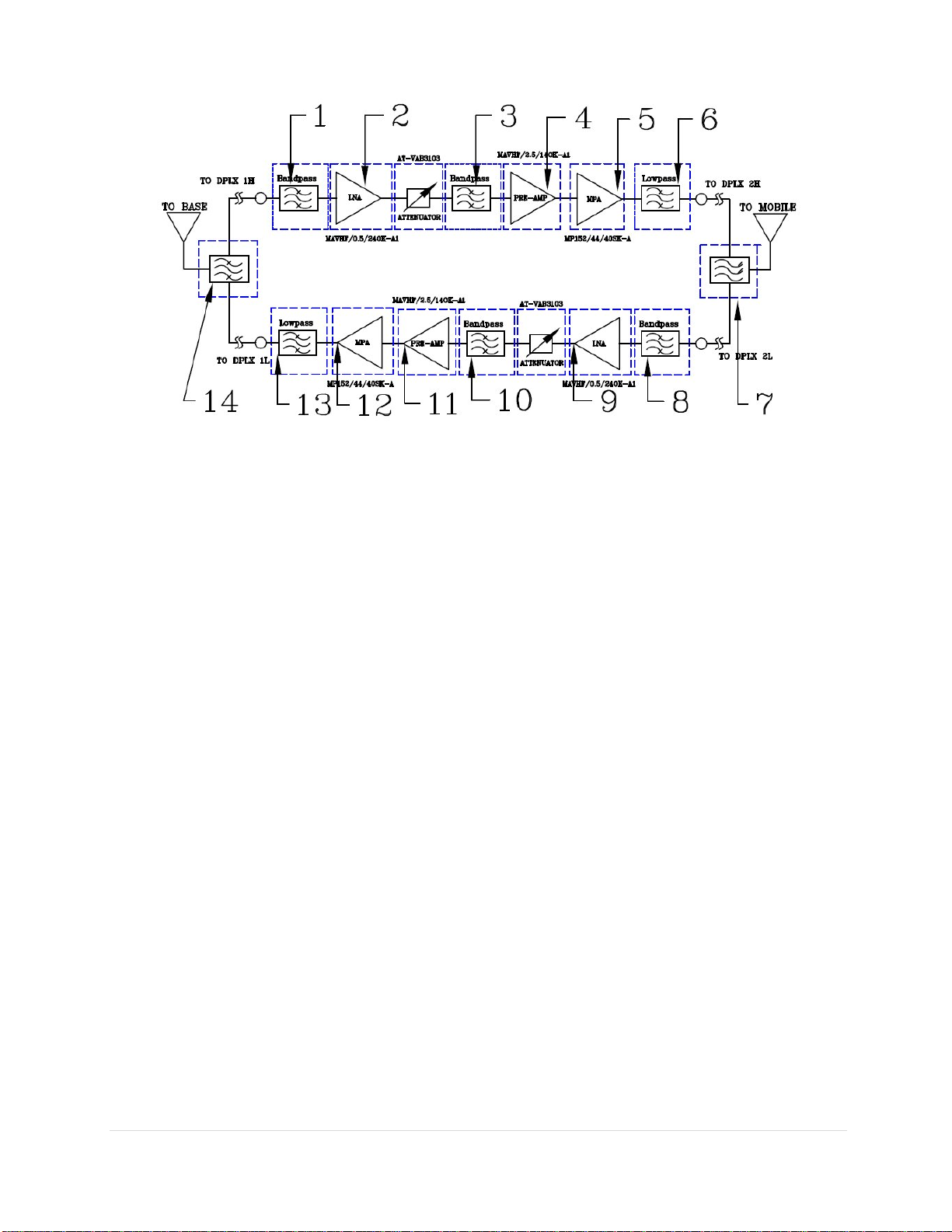
BlockDiagramDrawing:
Figure 1
1. First stage Internal Filter Downlink -This highly selective filter provides additional
rejection for increased isolation.
2. Downlink LNA- Is a low noise amplifier which offers 26 db Gain and establishes the
Noise Figure of the downlink path.
3. Internal Filter Downlink - This highly selective filter gives additional rejection for
increased isolation.
4. Downlink Pre-amp - Is a low noise amplifier that drives the downlink MPA and offers
16dB Gain.
5. Downlink MPA - Is a medium power amplifier with an ALC circuit which offers 42dB
Gain.
6. Low Pass Filter Downlink- This low pass filter provide a rejection of harmonics.
7. Output Diplexer – Has a low bandpass insertion loss and high selectivity for one distinct
downlink/uplink frequency band.
8. First stage Internal Filter Uplink - This highly selective filter gives additional rejection
for increased isolation.
9. Uplink LNA- Is a low noise amplifier which offers 26 db Gain and establishes the
Noise Figure of the Uplink path.
10. Internal Filter Uplink - This highly selective filter gives additional rejection for
increased isolation.
11. Uplink Pre-amp - Is a low noise amplifier that drives the Uplink MPA and offers 16dB
Gain.
12. Uplink MPA - Is a medium power amplifier with an ALC circuit which offers 42dB
Gain.
13. Low Pass Filter Downlink- This low pass filter provide a rejection of harmonics.
14. Input Diplexer – Has a low bandpass insertion loss and high selectivity for one distinct
downlink/uplink frequency band.
4 | Page
Page 5

ElectricalSpecifications:
BDA-VHF-33/33-80-20RU18
Specifications
Frequency Range
Bandwidth
Minimum passband separation
Pass band Gain @ min attenuation : 80 dB (Max.)
Typical
: 138-174 MHz
: 1-5 MHz
: 2 MHz
Variable Step Attenuator Range
(1-dB steps)
Gain Flatness
Noise Figure @ +25⁰C at Max. gain
3rd Order Intercept point
@ 2 tones +30dbm each
Composite Output Power : +33 dBm (Typ.)
Output Power ALC Set : +33 dBm (Typ.)
Input/ Output Impedance
VSWR (Input/Output)
Power Supply 110VAC/1.1 Amp; 240VAC/0.5 Amp
: 0-31 dB
: ±1.5 dB (Typ.)
: 5.5 dB (Max.) 5.0 dB (Typ.)
: +54 dbm
50 Ohms
1.5: 1 (Max.)
50 to 60 Hz
5 | Page
Page 6

MechanicalSpecifications:
Size : 40.0 x 21.0 x 22 inch
RF Connectors : N-Type Female
Weight : < 212 lb / (84 kg) approx.
(Additional Filter Rack not included)
EnvironmentalConditions:
The unit is designed for indoor applications:
Operating temperature: - 20°C to +50°C
Storage temperature: - 40°C to +85°C
FCCNOTE:
The product has been tested and found to comply with the Booster requirements per
FCC Part 90
This is a Class B device.
ICNOTE:
The product has been tested and found to comply with the Zone Enhancer requirements
per RSS-131.
6 | Page
Page 7

BDACONNECTIONS:
The BDA AC power is accepted through a standard 3-wire male plug (IEC-320) with
phase, neutral and ground leads. The AC power is wired to a high efficiency DC
switching power supply which is CE and UL approved. The power supply runs the
amplifiers and the Power On lamp. The metal enclosure of the BDA is connected to
ground.
An optional 9-pin D-Sub connector provides failure alarm output contacts (see diagram
next page) as well as an optional 12 VDC (250 mA) auxiliary output.
The RF connections are made via two type “N” female connectors. The RF connector
labeled “BASE” must be connected to the antenna pointing towards the base station.
The RF connection labeled “MOBILE” must be connected to the antenna facing the area
to be covered by the BDA.
The RF connections must be made through cables with characteristic impedance of 50
ohms.
The isolation between the base station antenna and the mobile antenna should be
at least 12 dB higher than the BDA gain. Isolation less than this value can cause
gain ripple across the band. Isolation equal to or less than the BDA gain will give
rise to oscillations which will saturate the amplifiers and possibly cause damage
to the BDA.
RFEXPOSUREWARNING:
In order to comply with the FCC RF exposure requirements, the BDA-VHF-33/33-80-20RU18
antenna installation must comply with the following:
Yagi type or similar directional antenna must be installed so as to provide a minimum separation
distance of 12 inches (30 cm) between the antenna and persons within the area. (This assumes
an antenna with gain of 5.65 dBi, VSWR ≤ 1.5:1, Zo= 50 ohms)
The Omni directional (or leaky cable ) must be installed so as to provide a minimum separation
distance of at least 8 inches (20 cm) between the indoor antenna connected to the RF booster
and the human user’s body within the area. (This assumes an antenna with gain of 0-2 dBi,
VSWR ≤ 2:1, Zo= 50 ohms).
7 | Page
Page 8

MechanicalOutlineDrawings:
Optional DC Power Input (S1)
Figure 2
The alarm monitors current of both uplink and downlink
amplifiers. An alarm condition will occur if either uplink or
downlink amplifiers are over or under its current tolerance
or if there is no DC power present.
Conditions for Optional Alarm
Relay Shown in Non
Figure 2a
-Alarm Condition
8 | Page
Page 9

OptionalBatteryBackUpConfiguration:
15 Amp Fuse
+ +
15 Amp
-
Battery
Back-Up Time
12 Volt
Lead-Acid
Battery
Figure 3: Optional Battery Back-Up Configuration
- -
+ Battery of
Recommend Battery
Rated Capacity
(20 Hour Rate)
1.5 Hour
2.5 Hours
3 Hours
5 Hours
Note: We do not guarantee specifications under Battery Back-Up power.
4.3 Amp Hours
7.2 Amp Hours
8.6 Amp Hours
14.4 Amp Hours
12 Volt
Lead-Acid
Battery
-
Typical DC Current
Rating for
BDA-XXX-33/33-80
2.3 Amps
2.3 Amps
2.3 Amps
2.3 Amps
9 | Page
Page 10

BDAInstallation:
DO NOT APPLY A.C. POWER TO THE BDA UNTIL CABLES ARE
CONNECTED TO BOTH PORTS OF THE BDA AND
1. Set the BDA Rack on the floor or mount on a wall (where applicable). Using
appropriate screws and anchors, attach the BDA to the wall at the four mounting holes
on the side flanges. (Special version not shown in this manual).
2. Ensure that the isolation between the donor antenna and the service antenna is at
least 12 dB greater than the BDA gain. (Use the higher of the Uplink and Downlink
gains reported on the BDA test data sheet).
3. Connect the cable from the donor antenna to the BDA connector labeled “BASE” and
the cable from the service antennas to the BDA connector labeled “MOBILE”.
4. See main Panel of the BDA and verify that both of the Uplink and Downlink
attenuation is set to 31 dB via dial Attenuator.
5. Connect the AC power cord to the BDA and then to the power source. Verify that the
“Power ON” lamp is illuminated.
Installation of the BDA is now complete. To adjust the gain controls to suit the specific
signal environment, refer to the next section of the manual.
: For repeat installations of existing equipment, make sure the attenuation is
Note
positioned to its maximum setting (31 dB). After verification attenuation, follow the
above steps starting with step 1.
THE ANTENNAS.
10 | Page
Page 11

BDAOperation:
Refer to figure 4 for adjustment access location and label.
Variable Step Attenuator
BDA gain can be attenuated, for Uplink and Downlink separately, up to 31 dB in 1 dB
steps using the variable step attenuator (Figure 4). To adjust the attenuation up to 11
dB, use the dialer on the front panel. To adjust the attenuation up to 31 dB, set the
thumbnail switch to +10 dB, and then dial in the remaining attenuation via the dialer.
BDA gain may be determined by subtracting the attenuation value from the gain reported
on the BDA Test Data Sheet for that side of the unit. The attenuators are labeled for
Uplink and Downlink.
Attenuation System Gain Attenuator Position
0 80 Both thumbnail switches
down and the dialer on zero
5 75 Both thumbnail switches
down and the dialer on five
10 70 Both thumbnail switches
down and the dialer on ten
15 65 One thumbnail switch up
and the dialer on five
20 60 One thumbnail switch up
and the dialer on ten
25 55 Two thumbnail switches up
and the dialer on five
31 49 Two thumbnail switches up
and the dialer on eleven
Table 2
ALC (Automatic Level Control)
To minimize intermodulation products, each amplifier in the BDA contains an ALC
feedback loop. The ALC circuit senses the output power and limits it to the factory preset
level of +33 dBm.
The ALC function is integrated in each amplifier. A red indicator lamp located on each
amplifier illuminates when output power exceeds the ALC set point.
To establish proper operating gain on the Uplink and Downlink sides, start with the
Downlink. Verify that the attenuation is set for 31 dB (minimum system gain). Observe
the red indicator lamp on the Downlink amplifier. Units are shipped with maximum
attenuation. Decrease attenuation one step at a time until the lamp is lit. Then, increase
the attenuation until the lamp goes off. Repeat the process for the Uplink. The level
indicator is accurate to +/- 0.4 dB of the ALC set point.
11 | Page
Page 12

Operation of the BDA at minimum attenuation with greater than -45 dBm average
power incident on either BASE or MOBILE port can cause damage to the BDA.
VariableAdjustmentAccess/LEDDescription:
VisualAlarmsandManualGainAdjustment
Figure 4
Figure4
12 | Page
Page 13

DiagnosticGuide:
The BDA provides long term, care-free operation and requires no periodic maintenance. There
are no user-serviceable components inside the BDA.
This section covers possible problems that may be related to the installation or operating
environment.
a. Gain Reduction
Possible causes: Defective RF cables and RF connections to antennas, damaged antennas.
b. Excessive Intermodulation or Spurious
Possible causes:
Amplifier oscillation caused by insufficient isolation. The isolation between two antennas is given
by the equation:
Isolation = 92.5 + 20 Log (F x D) – Gt – Gr
Where:
F = frequency (GHz)
D = separation (Km)
Gt = transmit antenna gain (in the direction of the receive antenna).
Gr = receive antenna gain (in the direction of the transmit antenna).
For example, at the VHF frequencies, the antenna isolation at 100 m separation is about 65.5 dB
for omni-directional antennas (0 dB gain). To increase isolation, the antennas should have higher
directivity and must be pointed away from each other.
c. Occasional Drop-out of some Channels
Possible causes: One channel with very strong power dominates the RF output of the amplifier.
13 | Page
 Loading...