

GW4GTE RAT5 Information Manual
RAT5 Information Manual 1.2.0
August 2010
This manual is the complete reference document for RAT5, containing all aspects of
construction and operation.
This manual refers to RAT5 hardware version 1.2
Please check you are reading the latest version of this document by checking
www.s9plus.com for any updates.
Please read this document fully before commencing construction
There are bound to be errors – please report any you find !
© GW4GTE 2010
www.s9plus.com
RAT5 Manual version 1.2.0
RAT5 Information Manual version 1.2.0 © GW4GTE 2010 Page 2 of 29
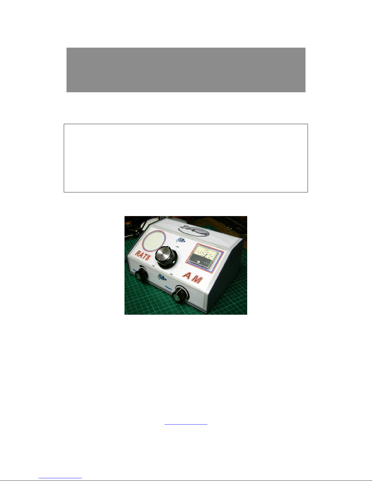
RAT 5
A Single-Conversion AM Receiver Kit for 160m or 80m
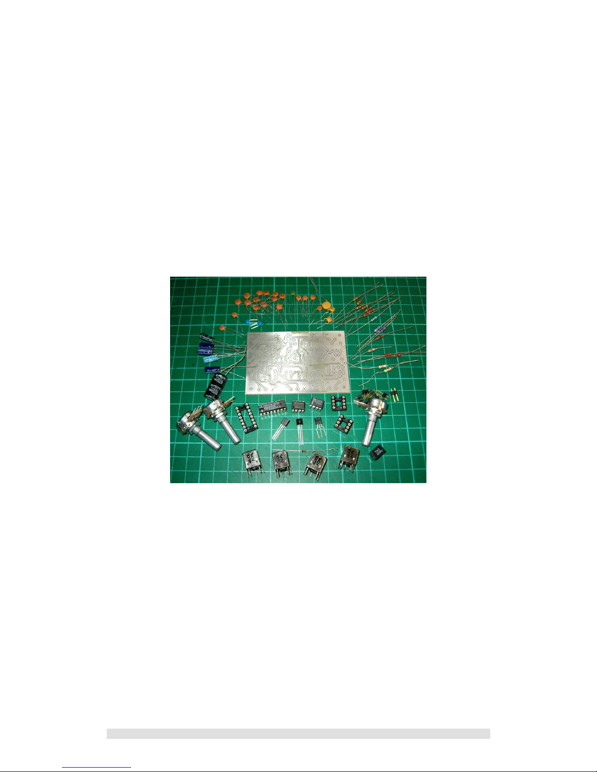
RAT5 kit of parts
Easy to Build
This kit is suitable for constructors with little or no previous experience of kit-
building. A basic level of soldering ability is however required. All components
are through-hole mounted i.e. no surface mount parts.

RAT5 Manual version 1.2.0
RAT5 Information Manual version 1.2.0 © GW4GTE 2010 Page 3 of 29
Contents
1 Introduction………………………………..……….….…….. 4
1.1 Modification Record - updates and corrections
2 Circuit Description……………………….…………...……. 7
2.1 Key Features
2.2 RF / IF Circuits
2.2.1 RF Filter
2.2.2 Local Oscillator
2.2.3 IF Filter
2.3 AF and Squelch circuits
2.3.1 Squelch
2.3.2 Audio Filtering
2.3.3. Audio Amplifier
3 Construction….……………………………………..……… 10
4 Testing and Alignment …………………………………… 13
4.1 Power-off Tests
4.2 Power-on Tests
4.3 Local Oscillator alignment
4.4 IF and RF Alignment
4.4.1 IF Alignment
5 Interfacing …………………………………………….…….. 18
5.1 Connection Method
5.2 Connections
5.3 Connecting an S-Meter
5.3.1 Calibration
5.4 Operation with a transmitter
5.5 Squelch Out
5.6 Power Sources
5.7 Choice of enclosure and Dimensions
6 Troubleshooting………………………..…………….…….. 22
6.1 Continuity checks
6.2 Voltage checks
7 Appendices…………………………………………….…….. 23
7.1 Parts List
7.2 Circuit diagrams - larger version
7.3 PCB Layout
7.4 “Anti-SSB” AGC modification for nuisance-free monitoring
7.5 Builder’s Gallery

RAT5 Manual version 1.2.0
RAT5 Information Manual version 1.2.0 © GW4GTE 2010 Page 4 of 29
1. Introduction
What is it?
The RAT5 is a single conversion AM receiver for 80m and 160m (operation on other
frequencies is also possible).
The receiver is based on the TDA1072A AM receiver IC which although obsolete is still
available in quantity from at least one source and a reasonable number has already been
obtained for kit builders.
The low cost and ease of construction make this an ideal club project, and to this end
component values are also provided to cover the Medium Wave where signals to tune into
are plentiful. No previous experience of kit-building is required, just basic soldering skills.
What does RAT5/FAT5 mean?
For some years now the author has been playing about with home brew solid state AM
transmitters, largely based on solid-state Class-E designs using low cost FETs. This is the socalled FAT5 series.
The FAT5 name came from the original idea of making a solid state version of the AT5, using
FETs. So, FET-AT5 became truncated to FAT5. RAT5 is an AM receiver to go with the FAT5
transmitter project. Maybe the complete RX/TX could be the FAT-RAT project?
Is there a kit?
Yes. Based around a 3”x2” drilled and tinned single-sided fibre-glass PCB the kit contains all
the components for the project. All that is required in addition is an antenna, power source,
loudspeaker, control knobs and case. For ordering details check www.s9plus.com or email
the culprits below.
It’s a big manual for a little kit?
This is the complete reference document containing everything about RAT5. To just build the
kit most of the sections can be ignored. Please read the entire document before starting
construction.
Project Support
This is a supported project, with free advice offered before, during and after construction.
Who to Blame
Circuit design and PCB layout by Dave GW4GTE.
PCB production and kit distribution by Eric GW8LJJ.
Contact Points
Dave GW4GTE: gw4gte @s9plus.com; address is QTHR or see QRZ.com
Eric GW8LJJ: eric@ericedwards.co.uk ; address is QTHR or see QRZ.com
Acknowledgements
The author extends grateful thanks to ‘Ferric’ Eric GW8LJJ for the production of such
excellent PCBs at ham-friendly prices. It is no exaggeration to say this and several other
designs would never have seen the light of day as completed projects without Eric’s
enthusiasm and support.

RAT5 Manual version 1.2.0
RAT5 Information Manual version 1.2.0 © GW4GTE 2010 Page 5 of 29
1.1 Modification Record
Changes to the information manual
This manual is Version 1.2.0. The previous manual was version 1.1.4
• A drawing error was reported in the previous circuit diagrams figure 2.1 and
Appendix 2 : VR1 was drawn as fed from the C13 side of R2. It should be
connected to the C28 side. This is now corrected.
• FL1 in the circuit diagrams of figure 2.1 and appendix 2 is now annotated as
ALFY455GT to reflect the part change (see below)
• Appendix 3 (PCB layout) incorporates the track changes detailed below.
Changes to the PCB
The PCB to which this manual refers is version 1.2. The previous PCB was version 1.1.
New IF filter
PCB Version 1.2 incorporates a different 455kHz filter. We have now managed to
source a slightly narrower filter while keeping the kit price the same. The new filter is
+/- 4.5 Khz wide at -6dB, previously it was +/- 6kHz wide at -6dB. The filter pinout is
slightly different, requiring a modification to the PCB layout. If existing kit owners wish
to try the new filter and are happy to adapt the previous PCB the new filter can be
supplied as an upgrade. No other circuit changes are required.
Track modification
The PCB track around the pins of RV1, RV2 and RV3 have been thickened to provide
more strength when using the potentiometer fixing threads to support the PCB.

RAT5 Manual version 1.2.0
RAT5 Information Manual version 1.2.0 © GW4GTE 2010 Page 6 of 29
2. Circuit Description
Abbreviations: LO – Local Oscillator, CW – clockwise, CCW – Counter-clockwise
PD – Potential difference, MW – Medium Wave, RF – Radio Frequency
IF – Intermediate Frequency, IC – Integrated circuit, AM – Amplitude Modulation
AF – Audio Frequency, AGC – Automatic Gain control, RX – Receive(r)
RAT5 is a varicap tuned single conversion superhet of conventional design based around the
TDA1072A AM receiver IC. Figures 2.2 (RF/IF) and 2.5 (AF/Squelch) show the circuit in its
entirety.
2.1 Key features
High sensitivity
Signals around 1uV PD are detectable.
Good AM selectivity
A 6-pole 455kHz AM filter has been selected for good adjacent channel selectivity. Bandwidth
is +/-4.5 kHz at -6dB and +/-10kHz at -50dB. (previous version used a 6kHz filter).
Input bandpass filter
A two stage bandpass filter provides adequate protection against image breakthrough.
Carrier Squelch
The TDA1072A does not provide a squelch facility as it is intended for broadcast AM
reception in consumer equipment. In amateur use a squelch feature is useful and this has
been designed into the circuit.
Low power consumption
RAT5 consumes typically less than 50mA from a 9V to 15V supply making it suitable for
battery operation.
2.2 RF/IF circuits
Refer to Figure 2.1
The only active component in the RF/IF section apart from regulator VR1 is U1, a TDA1072A
AM receiver IC around which everything else based. U1 performs all the main functions of a
single conversion AM superhet including RF amplifier, LO, mixer, detector, AF pre-amp and
AGC system, considerably simplifying the supporting circuitry.
2.2.1 RF Filter
With a 455kHz IF the image frequency is 910kHz away from the wanted signal. T1
and T2 together with C1 C2 and C3 form a two section bandpass filter with sufficient
selectivity to prevent image breakthrough.
Toko KANK3333 RF transformers are used for T1 and T2 as well as for L1 and L2.
These are no longer manufactured by Toko, but equivalent transformers have
recently become available in quantity. For simplicity the bandpass filter is fixed tuned.
The added complication and expense of tracking varicap tuning is unnecessary for
the narrow range of frequencies the intended application covers i.e. AM frequencies
on 80m/160m
RAT5 Manual version 1.2.0
RAT5 Information Manual version 1.2.0 © GW4GTE 2010 Page 7 of 29
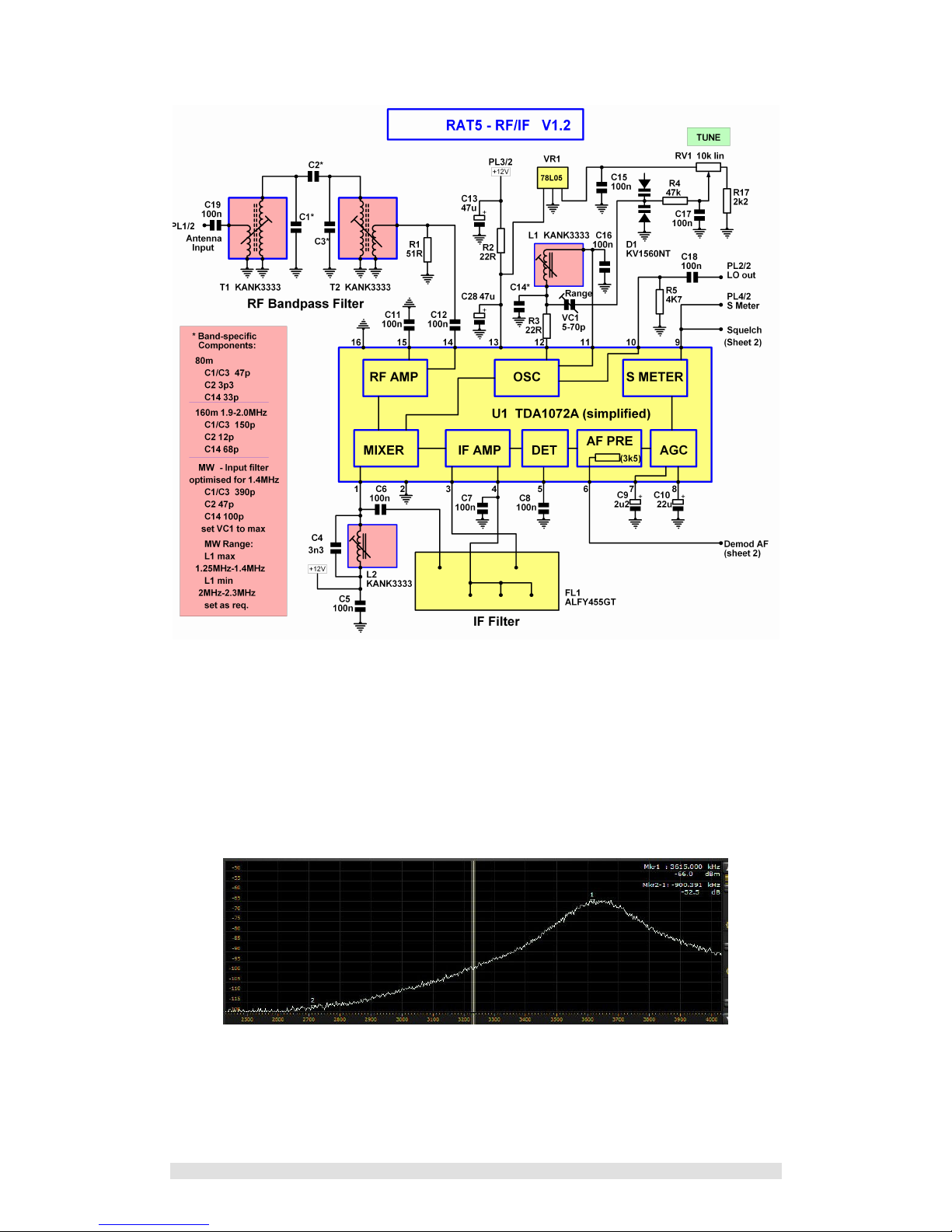
Figure 2.1 RF and IF circuit
A low-side LO on 80m and a high-side LO on 160m places the image in relatively
quiet parts of the spectrum. The image frequency for 3615kHz is 2705kHz and the
image frequency for 1963kHz is 2873kHz. Compare with say a low-side LO on 160m
which would produce an image frequency in the MW broadcast band!
Figure 2.2 below is an actual plot of the bandpass filter on 80m showing the image
attenuation for a receive frequency of 3615kHz
Figure 2.2 Actual plot of RF bandpass filter on 80m
RAT5 Manual version 1.2.0
RAT5 Information Manual version 1.2.0 © GW4GTE 2010 Page 8 of 29
2.2.2 Local Oscillator (LO)
The LO frequency is determined by L1 C14 and the series combination of VC1 and
varicap diode D1. VR1 provides a stabilised 5 V for tuning control RV1. VC1 can be
varied to control the tuning range provided by RV1. R17 limits the minimum tuning
voltage to around 0.9 V reducing the non-linearity at that end of the varicap’s tuning
characteristic.
The circuit values given are for a low-side LO on 80m and a high-side LO on 160m.
e.g. 3615kHZ RX, LO = 3160kHz ; 1963kHz RX, LO = 2418kHz
For Medium Wave operation it is suggested the LO runs on the high side.
The IC provides a buffered local oscillator output, and this is brought out to PL2 for
use with a frequency display (future add-on project) and to assist with setting up.
2.2.3 IF Filter
The IF tuned circuit L2/C4 is tuned to 455kHz giving a good match into the IF filter
FL1, a 6-pole ladder filter from Toko. This is a simpler solution than the circuit
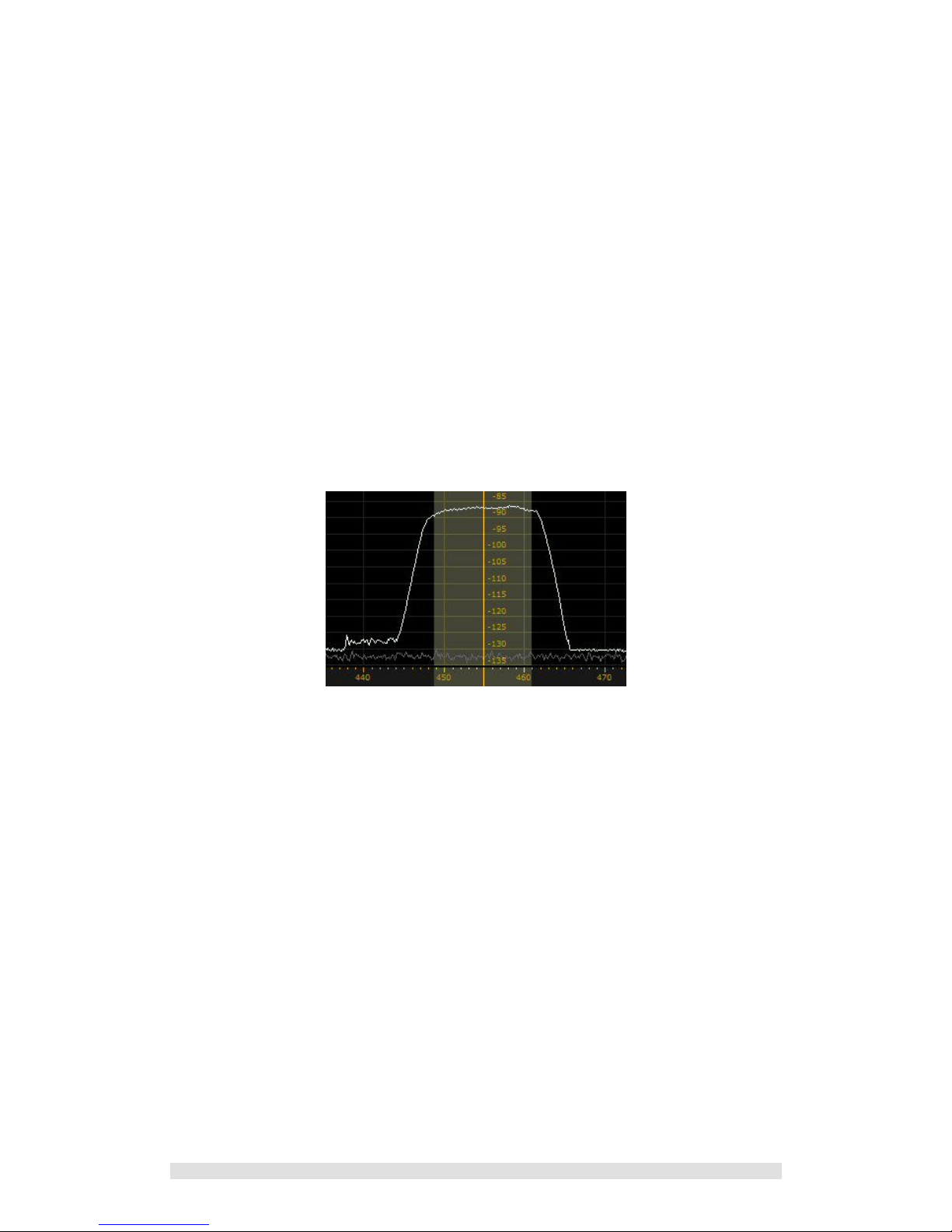
suggestions in the IC manufacturer’s data sheet. Figure 2.3 below shows an actual
plot of the IF passband. (Note the graph shows passband response only, not ultimate
out-of-band rejection for which a larger test signal would be required).
Figure 2.3 Actual plot of IF passband response of 6kHz filter
(4.5kHz filter now supplied – response similar but narrower).
C9 and C10 give time constants for the internal AGC circuitry in line with data sheet
recommendations. The AGC has a fast response which copes well with rapid signal
fading.
The S-meter output is brought out to PL4 for use with a meter or other display (see
Section 5.3). The same line feeds the squelch circuitry shown in Figure 2.4.
RAT5 Manual version 1.2.0
RAT5 Information Manual version 1.2.0 © GW4GTE 2010 Page 9 of 29
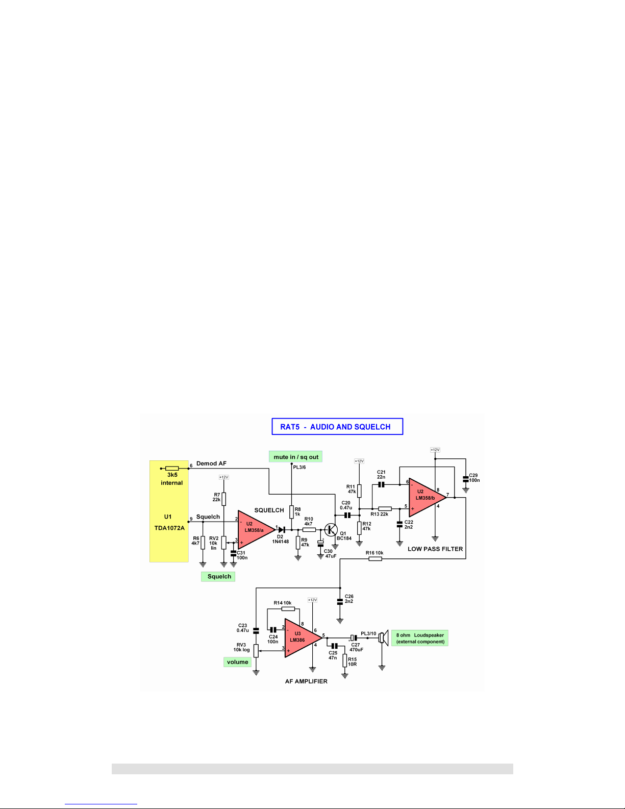
2.3 AF and Squelch circuits
Refer to Figure 2.4
2.3.1 Squelch
U2/a is one half of an LM358 op-amp IC, wired as a comparator. The LM358 was
chosen for its ability to function at near-ground input levels while working off a single
rail supply.
RV2 sets the voltage on the non-inverting pin. AGC volts are fed into the inverting pin.
With no input signal RV2 is adjusted such that pin 3 is more positive than pin 2. The
output on pin 1 is high, saturating Q1 via D2 and R10. Q1, working as a potential
divider with the U1 demodulated audio output impedance of 3k5 (as stated in
datasheet) attenuates the ongoing signal to inaudible levels.
When a carrier is received such that the AGC line at U2 pin 2 goes more positive than
the level on pin 3 the comparator output will drop to zero, cutting off Q1 and enabling
the audio path.
The time constant provided by C30 / R10 reduces squelch clicks, as does the use of
C20 to isolate Q1 from the bias chain R11/R12.
External override muting is provided via limiting resistor R8. U2 is isolated by D2.
Apply a positive voltage of 5V to 12V to PL3/6 to mute the receiver. This is intended
for transceiver use as a means of muting the receiver while keeping the local
oscillator running. C20 prevents squelch operation affecting the bias on U2/b, giving
a clean squelch function with no clicks or thumps.
Figure 2.4 Audio and Squelch circuit
PL3/6 can also be used as an output to drive a squelch LED (see Section 5.5). PL3/6
is high on mute and low when the squelch is open.
 Loading...