

Page 1
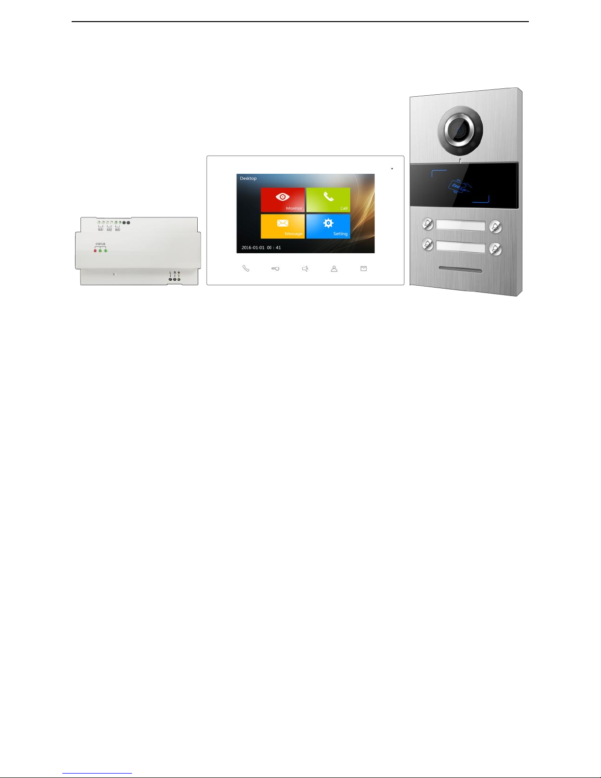
User Manual_T series
T-OS01/T-IS01
T-PS01
Page 2
Page 3

Catalog
Overview ..................................................................................................................................... 1
Product Introduction .................................................................................................................. 2
Indoor Station Appearance ................................................................................................2
Indoor Station Size ..............................................................................................................4
Interface Instruction of Indoor Station ..........................................................................5
Indoor Station Specification .............................................................................................6
Outdoor Station Appearance ............................................................................................7
Outdoor Station Size ......................................................................................................... 10
Interface Instruction of Outdoor Station ..................................................................... 11
Outdoor Station Specification .......................................................................................... 12
Power Supply Appearance ............................................................................................... 13
Power Supply Size
......................................................................................................... 15
Interface Instruction of Power Supply ........................................................................ 16
Power Supply Specification .............................................................................................. 16
System Connection .......................................................................................................... 17
Indoor Station-Basic Function & Settings ................................................................ .............. 18
Standby Interface .............................................................................................................. 18
Visitors’ intercom ................................................................................................ .............. 19
Monitor .............................................................................................................................. 21
Call Out ............................................................................................................................. 22
Message .............................................................................................................................. 23
Indoor Station Setting .............................................................................................................. 25
Ring Setting ....................................................................................................................... 25
Time setting ....................................................................................................................... 25
Language setting ............................................................................................................... 26
Advanced Setup ................................................................................................................ 26
Outdoor Station Settings .......................................................................................................... 29
Default Setting................................................................................................................... 29
Register Card Settings ...................................................................................................... 29
Unlock time setting ........................................................................................................... 30
ADD Setting ...................................................................................................................... 30
Installation ................................................................................................................................ 31
Where to install the outdoor station: ............................................................................... 31
Page 4

How to install outdoor station: ........................................................................................ 32
Where to install the indoor station .................................................................................. 33
How to install indoor station: ........................................................................................... 34
Page 5

1
Overview
This product is a video intercom system based on two wire analog solution, the system
uses two core wire to connect power supply, the outdoor station and indoor station. The
functions are as below:
Visual Intercom, Unlock;
Monitor;
4 indoor station in 1 house;
Intercom through the system’s unit;
TF card storage, screenshot and video record;
Support KNX home automation
Page 6
2
Product Introduction
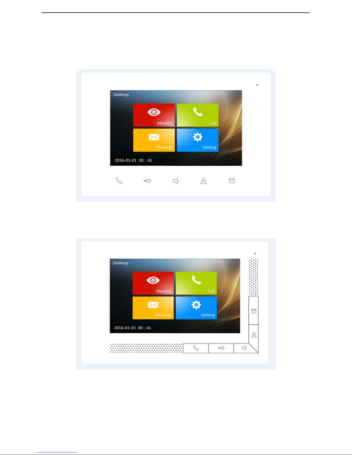
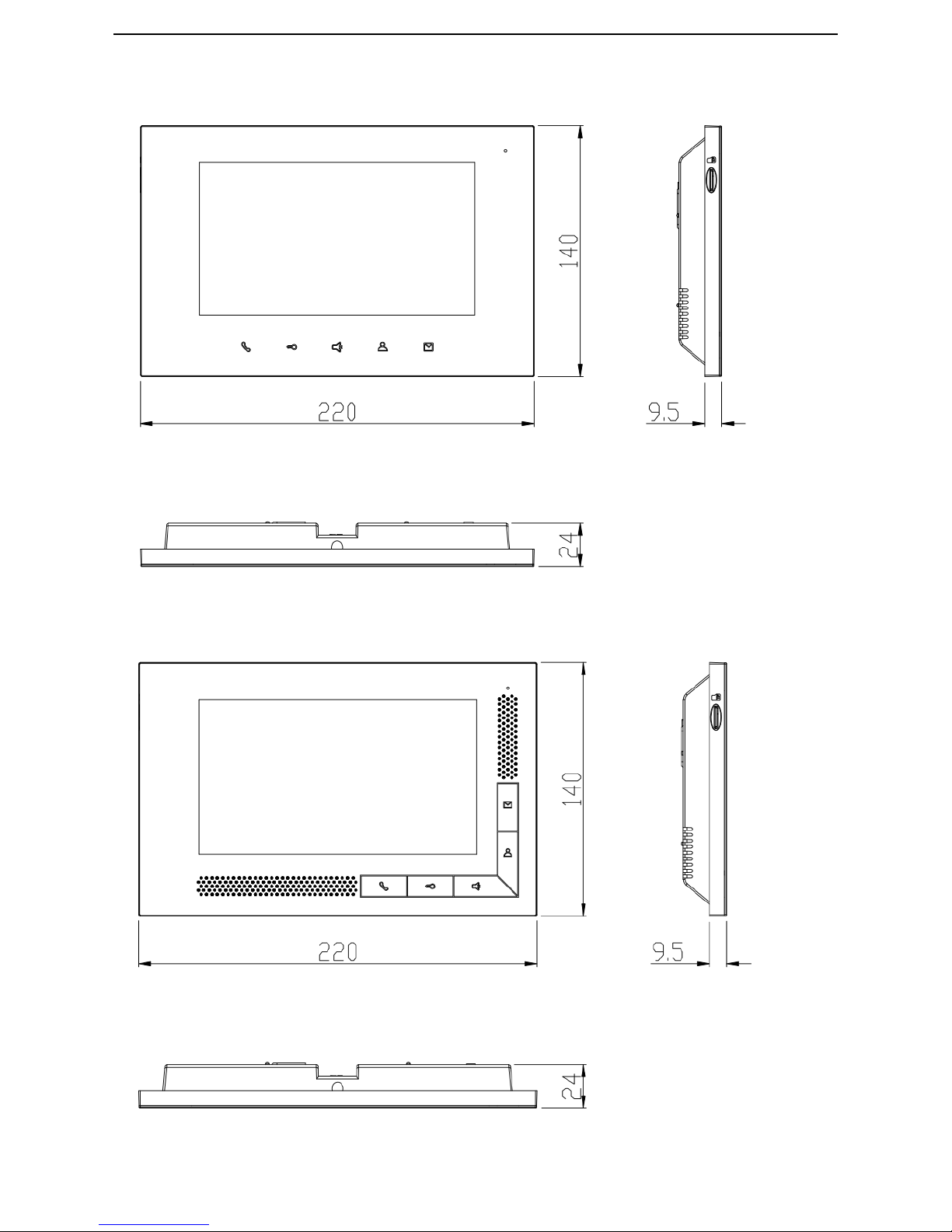
Indoor Station Appearance
Model:T-IS01-W L
Model:T-IS01-W H
Page 7
3
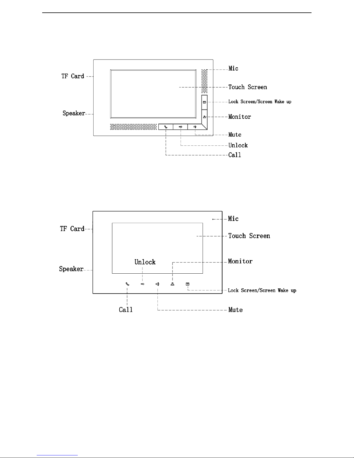
Model:T-IS01-W L
Model:T-IS01-W H
Page 8
4
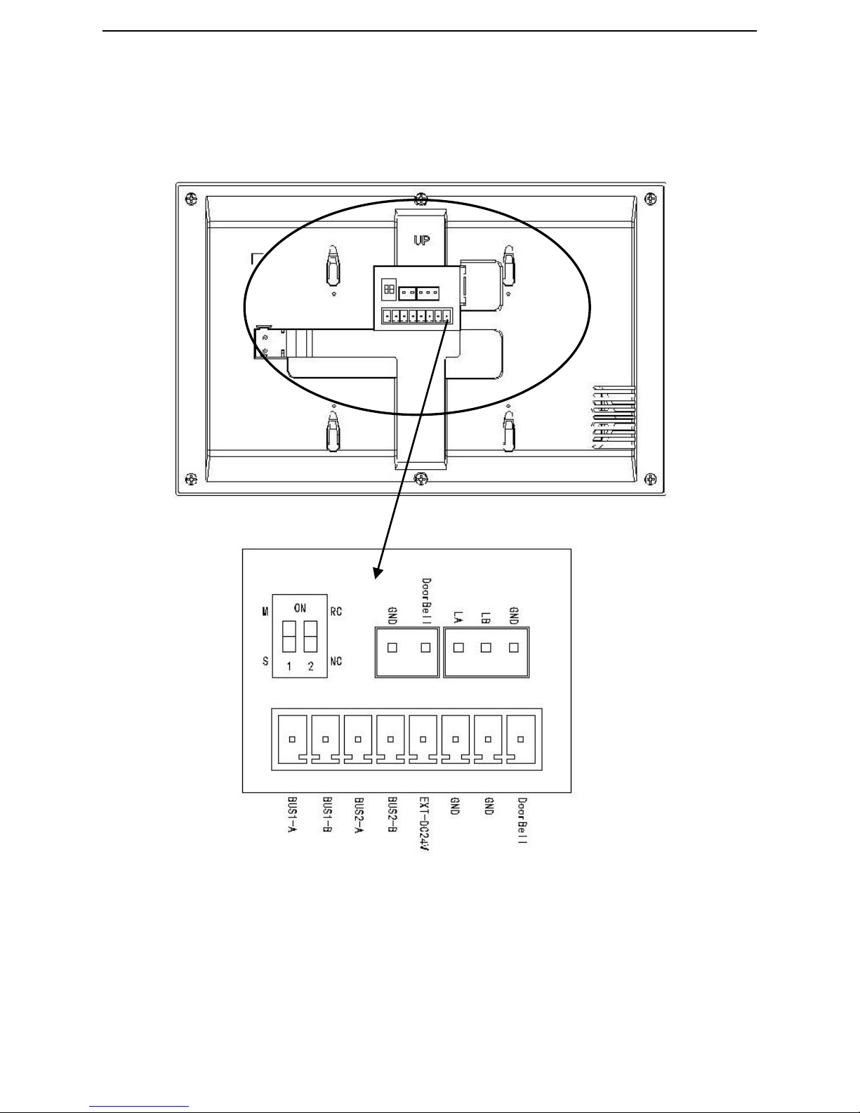
Indoor Station Size
Model:T-IS01-W L
Model:T-IS01-W H
Page 9
5
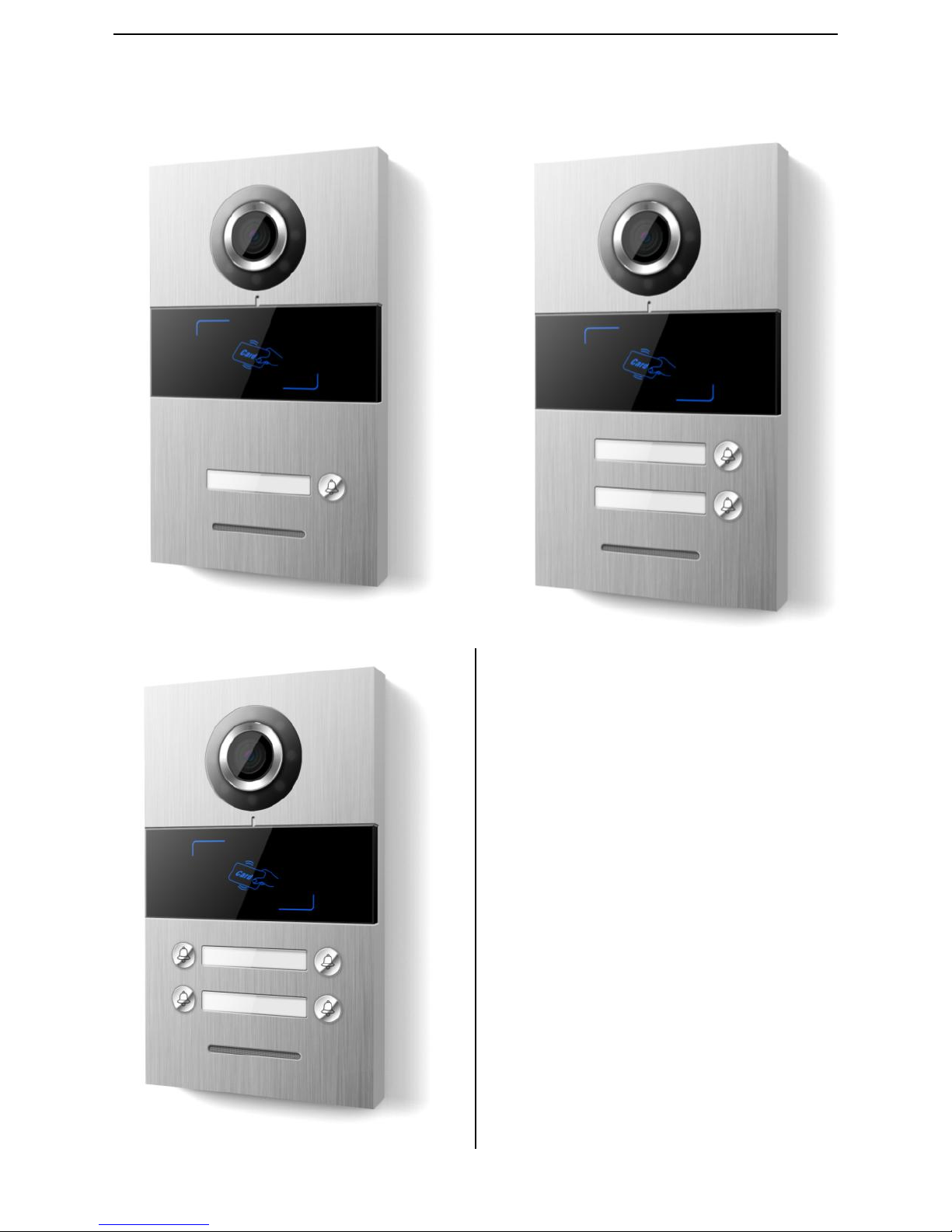
Interface Instruction of Indoor Station
②
①
③
④
Page 10

6
①:
BUS1-A BUS1-B:Bus Port 1;
BUS2-A BUS2-B:Bus Port 2;
EXT-DC24V GND:Auxiliary Power Supply 24V;
GND DoorBell:Interface of doorbell button;
②:
1:Setting on Master-Slave devic;
2:Impedance matching of video terminal;
③:Doorbell port;
④:
485 Expansion interface;
Note:
①
When impedance matching the video terminal of the last indoor station device, please
turn “2” on.
②
The bus port A & B are used for connecting the indoor station.
③
The master indoor station rings and screen wake up when it’s called in, but slave device will only ring but
not screen wake up.。
Indoor Station Specification
Working Voltage:DC 24~32V
Idle current
:≤
10 mA (DC 32V)
Working current
:≤
200 mA (DC 32V)
Screen:7 inches TFT
Resolution:800 * 480
TF Card: 2~32G (Class 10 preferred)
Dimension (L * W * D):220 * 140 * 24 mm
Page 11
7
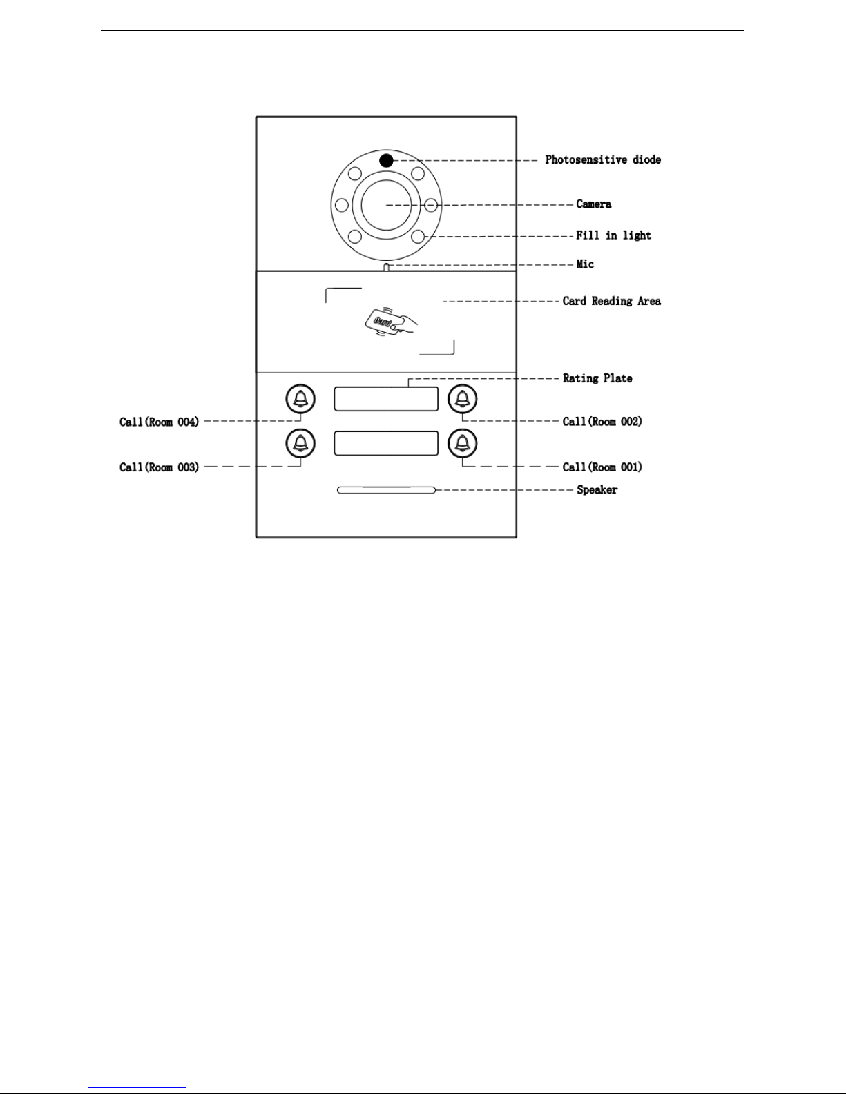
Outdoor Station Appearance
Note:
These models are for IC card only.
Model:T-OS01-S-IC-01
Model: T-OS01-S-IC-02
Model:T-OS01-S-IC-04
Page 12

8
Model:T-OS01-S-IC-01
Model:T-OS01-S-IC-02
Page 13
9
Note: The Call button are related to different indoor station, please refer to the indoor station settings.
Model:T-OS01-S-IC-04
Page 14
10
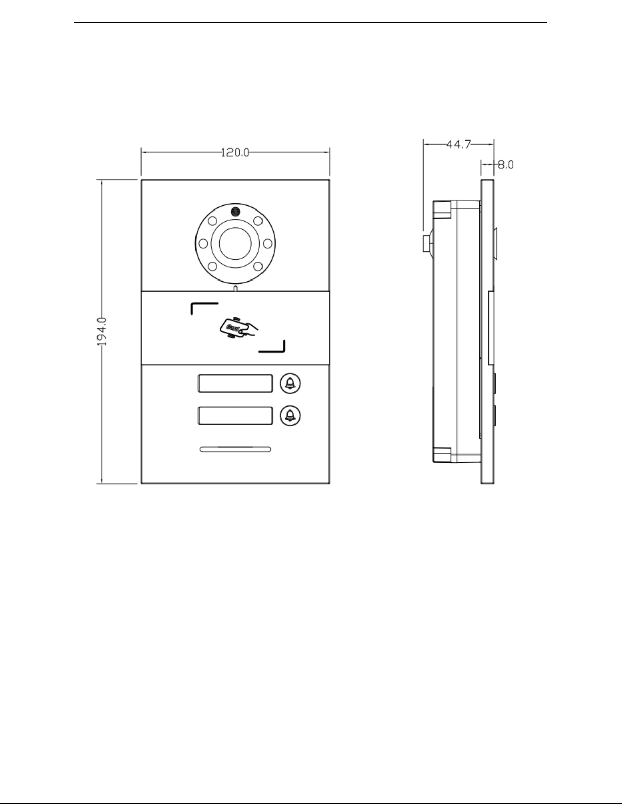
Outdoor Station Size
Note:The above image is based on T-OS01-S-IC-02, the other models are the same size.
Page 15
11
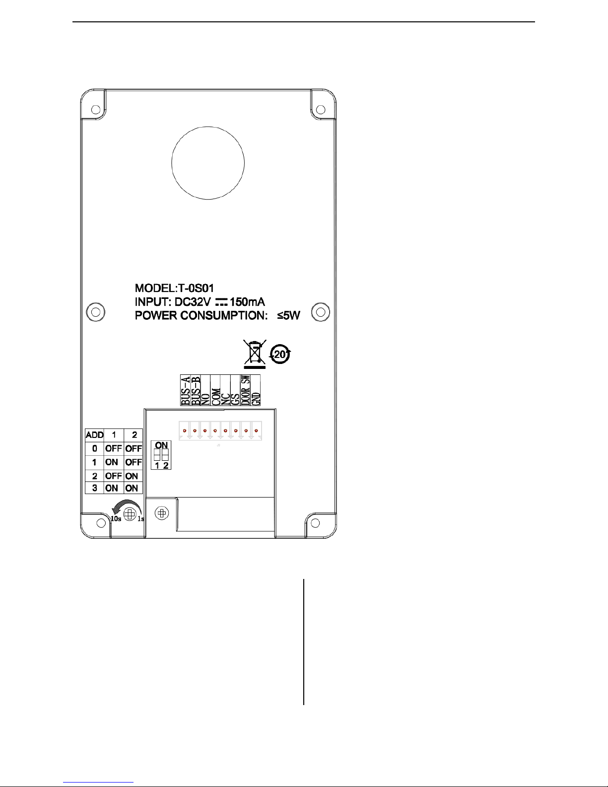
Interface Instruction of Outdoor Station
①:
BUS-A 、BUS-B:Bus Port;
NO、 COM 、NC :Normal on/off port;
GS :Door status checking;
DOOR SW:Unlock inside;
GND :Public Area;
②:
Unlock timing settings, details in page 30
③:
Outdoor Station ADD Settings, details in
page 30
①
②
③
Page 16

12
Outdoor Station Specification
Working voltage:DC 24~32V
Idle current
:≤
25 mA (DC32V)
Working current
:≤
150 mA (DC32V)
Camera type:CMOS PAL
Camera pixel:30W
Visual angle:90°
Fill-in light:White light
Size (L*W*D): 120 * 194 * 44.7 mm
Page 17
13
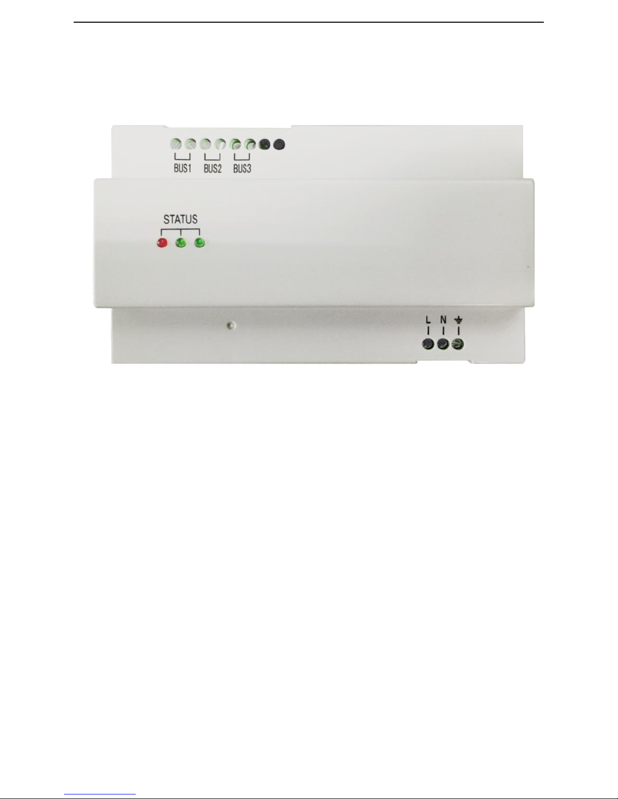
Power Supply Appearance
Model:T-PS01
Page 18
14
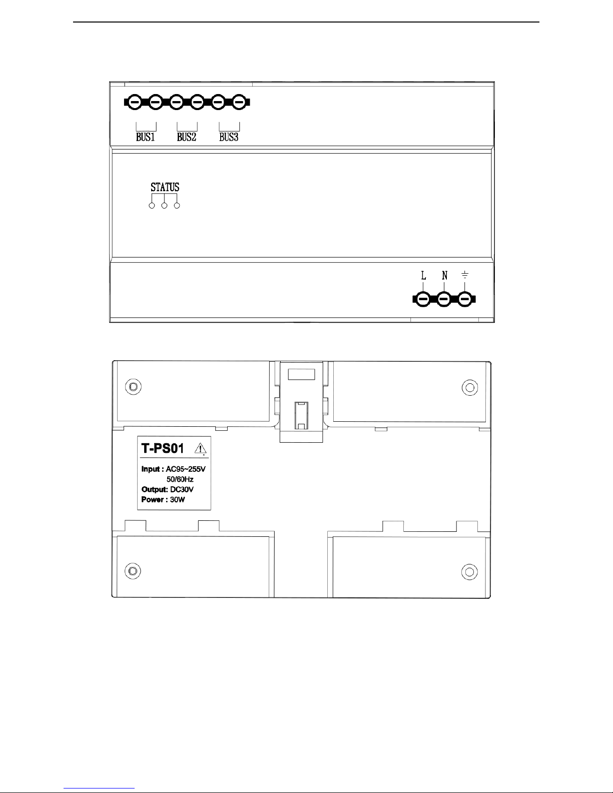
Front Side:
Back Size:
Page 19
15
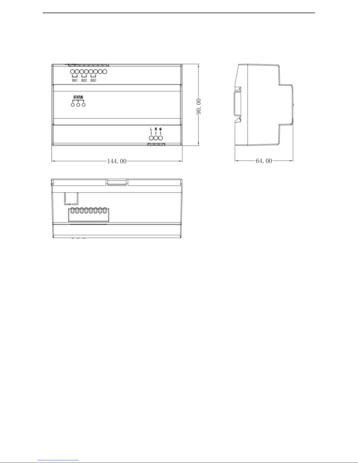
Power Supply Size
Page 20
16
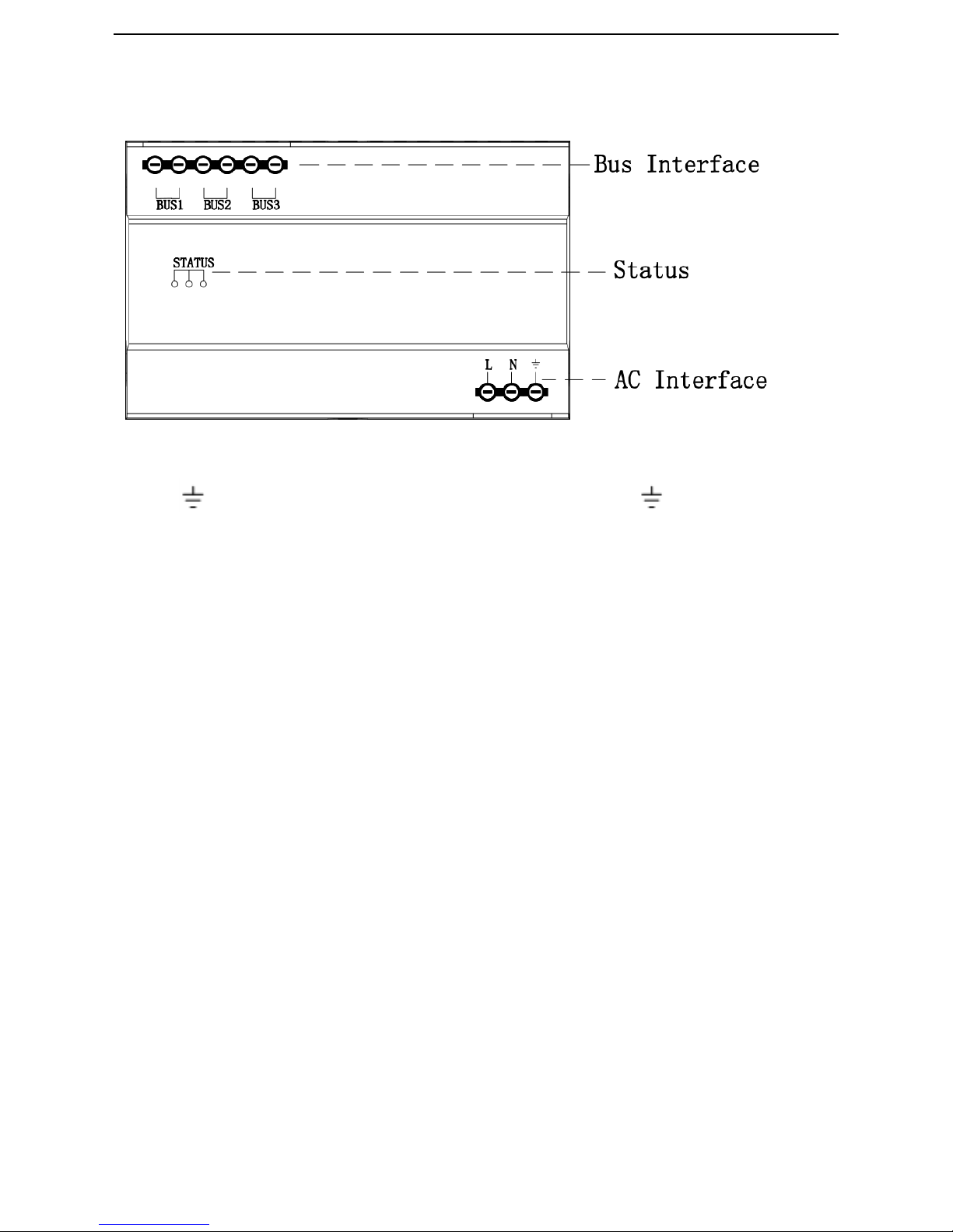
Interface Instruction of Power Supply
BUS1、BUS2、BUS3:Bus Interface;
L、N
、
:AC Port;L connect Live wire,N connect null wire
,
connect earth wire.
Note:
①
The left red light will flash while the working in the bus line.
②
The middle green light will be on while working, and flash while receiving date signal.
③
The right green light is for back up use
Power Supply Specification
Working input voltage:AC 90V ~ 255V 50/60Hz
Output voltage:DC 30V
Rated powert:30W
Size (L*W*D): 144 * 90 * 64 mm
Page 21
17
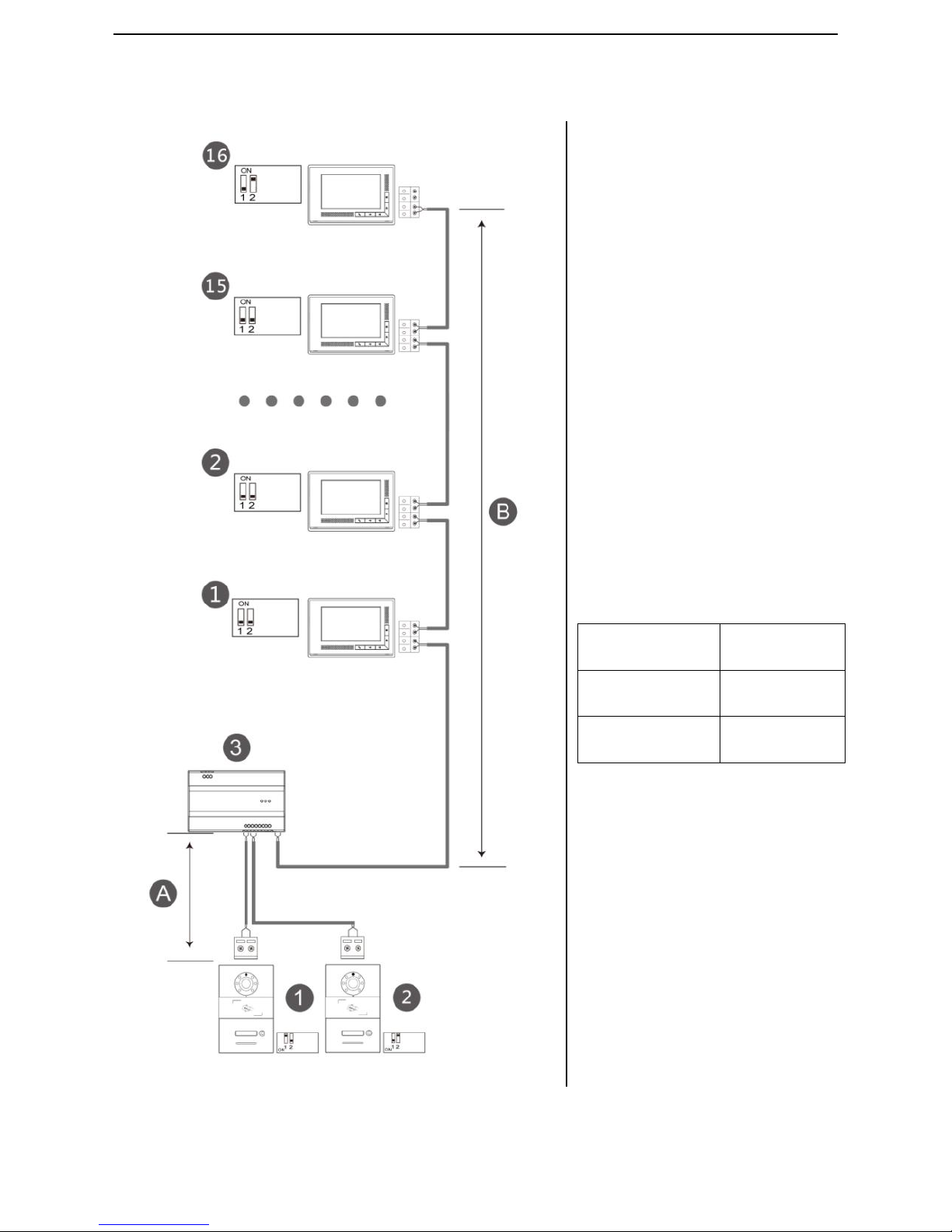
System Connection
Note:
① The most devices of system:
2 outdoor station+16 indoor station.
② The distance Ais the longest
length between outdoor station 1 & 2,
the distance B is the whole length
between the power supply and the
last indoor station. The wire as
below:
Wire
(A+B)
Length/m
RVV 2*0.75mm²
110
Twisted-pair
cable
160
Page 22
18
Indoor Station-Basic Function & Settings
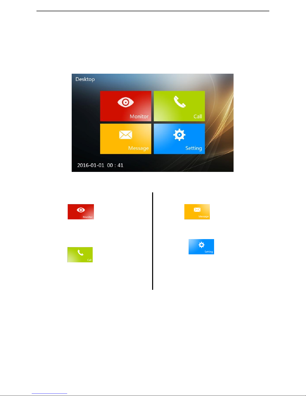
Standby Interface
1、 Monitor
touch icon to enter the
monitor interface,you can operate to
make snap or video record.
2、 Call
touch icon to enter Call
interface,you can make intercom among
indoor stations in a unit or among
different units;
3、 Message
touch icon to enter Message
interface,you can view the snap, video;
4、 Setting
Present icon to enter Setting
interface, you can set the tunes,
languages, display and configuration.
Page 23
19
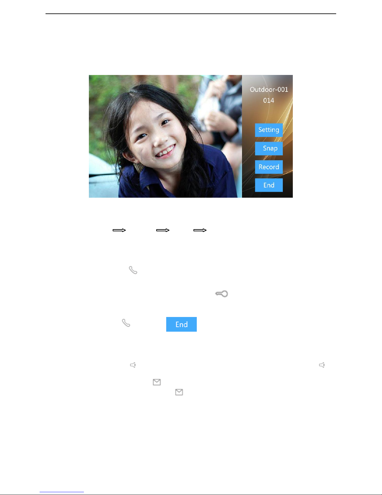
Visitors’ intercom
Ringing
Procedure:Ringing Intercom Unlock End
Incoming calls:
1、Visitors use the outdoor station to call the indoor station and the indoor station will ring.
2、After residents touch , the conversation begins.
3、During the conversation,the residents can touch to unlock the door,the call will
end up automatically after 5s the door unlocks.
4、The resident touch or touch to end up the call.
Note:
① While calling, touch to keep sound coming from outdoor station; In other status, touch to
mute the outdoor station and indoor station.
② While screen wake up, touch to turn off the screen (except the interactive interface like
calling, monitor),while the screen lock, touch to wake up the screen.
Page 24
20
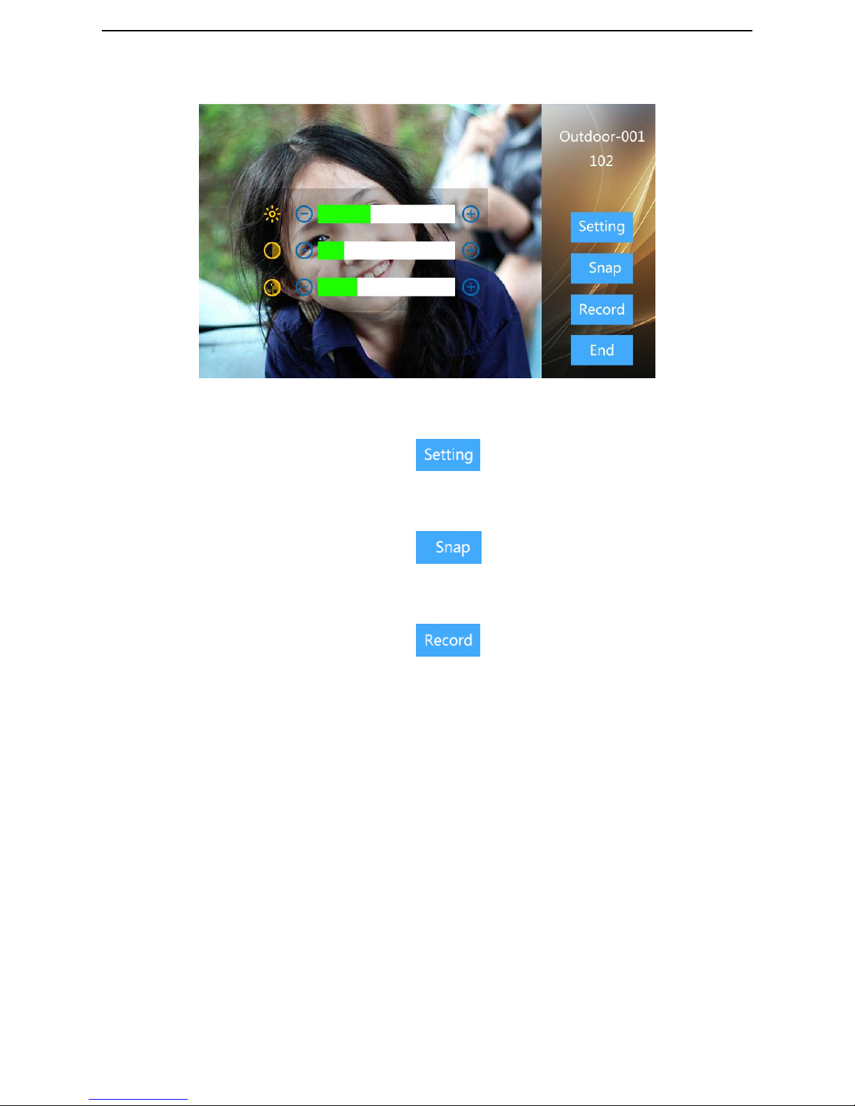
Setting
Setting:
1
、
While the visitors calling, you can touch for setting operation.
2
、
Setting: Brightness, contrast and chroma
Snap:
1
、
While the visitors calling, you can touch to make screenshot.
2
、
The snap pictures are stored in the call records.
Video Record:
1
、
While the visitors calling, you can touch to record the video.
2
、
The videos are stored in the call records.
Note:
With TF card inserted, the storage is 40 video or 1000 pieces of photos.
Page 25
21
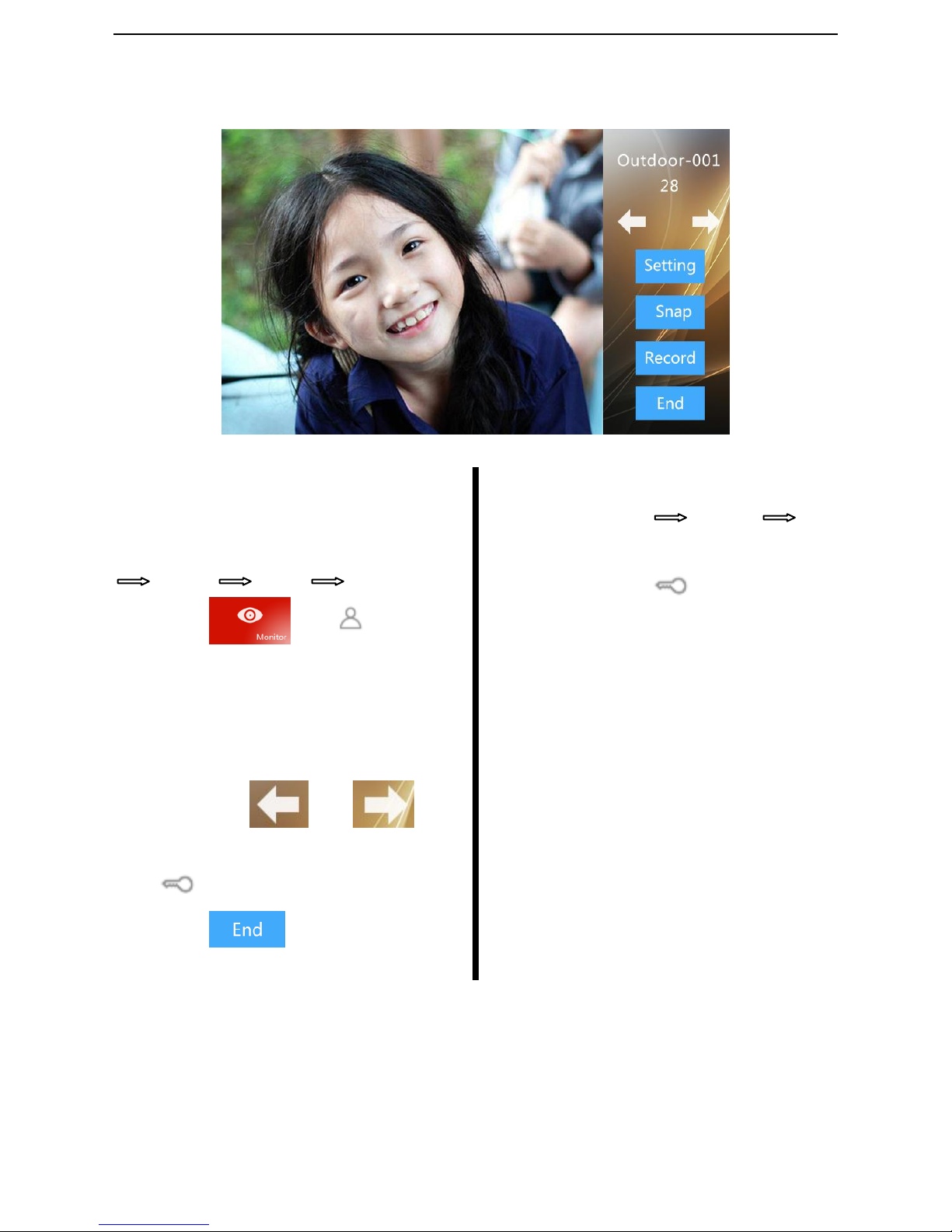
Monitor
Monitor
Monitor & Unlock
Procedure:
Select the monitor
Monitor Unlock End
1
、
Touch or icon, select
the monitor device type. The outdoor
station 1 (ADD 1) will be monitored
acquiescently
2
、
Monitor the sight
3
、
To monitor the outdoor station, you can
switch it by and .
4
、
While monitoring, the resident can touch
to unlock for the visitors.
5
、
Touch to end monitoring.
Visitors’ intercom
Procedure:Monitor Intercom End
While monitoring the outdoor station, the
resident can touch
to communicate
with visitors.
Page 26
22
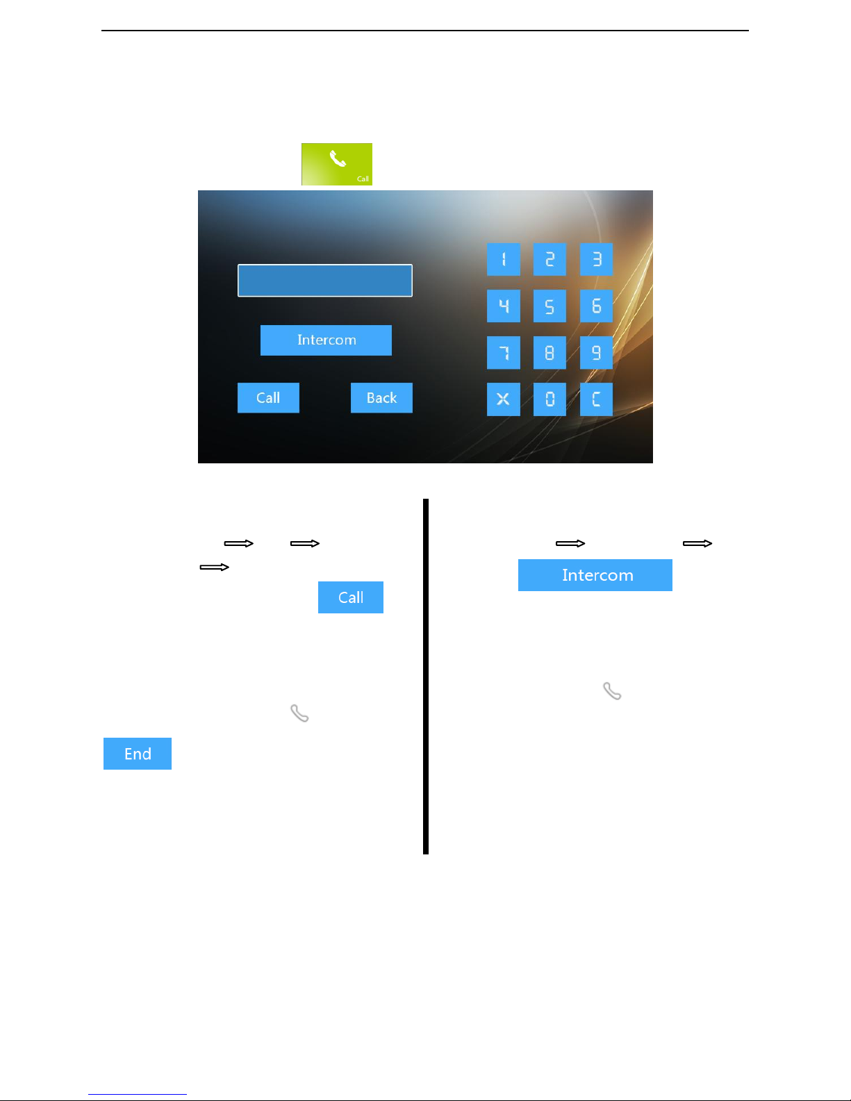
Call Out
On the main interface, touch to enter calling interface.
Call out
Units’ intercom
Procedure:Call Ring
Conversation End
1、Enter the room no and touch .
2、Hear ring back tone.
3、After the callee picks up, then start the
conversation.
4、The resident can touch or
to end up the intercom.
Rooms’ intercom
Procedure:Call Conversation End
1
、
Touch to start
the intercom.
2
、
Hear ring back tone.
3
、
The indoor station of calleer rings.
4
、
The resident touch to end up the
call.
Page 27
23
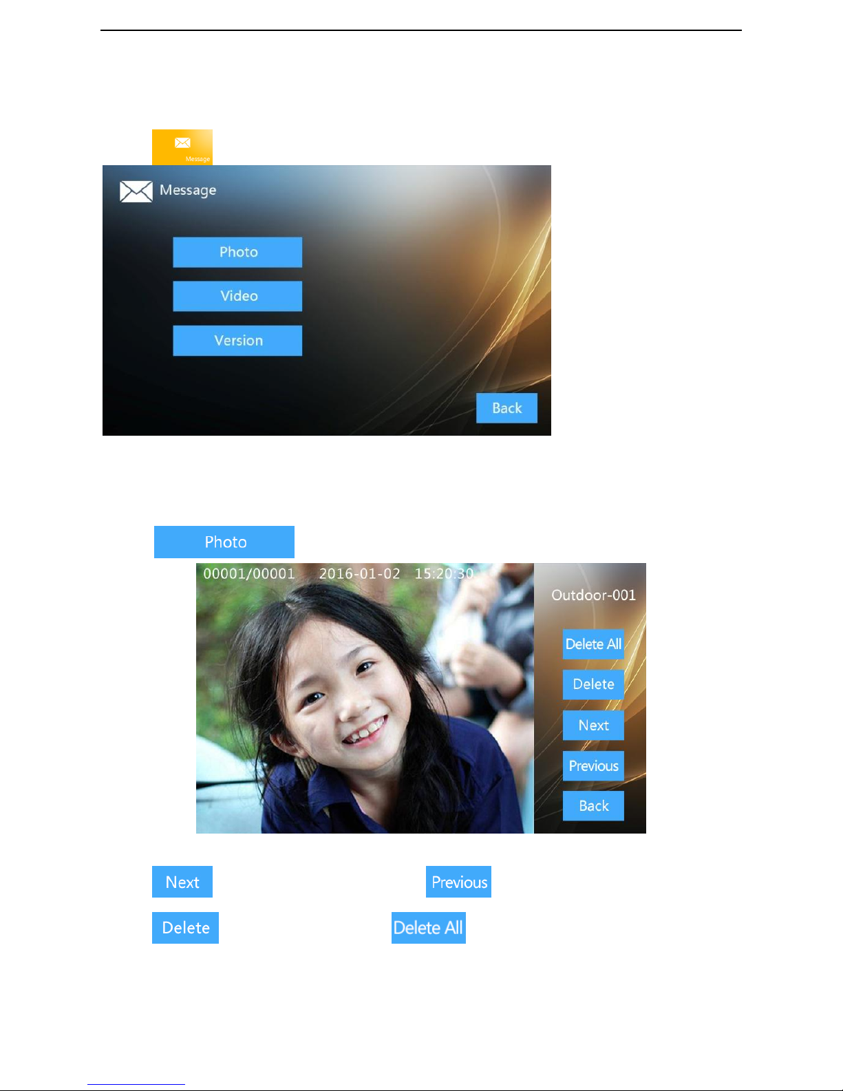
Message
Touch to enter message interface, check the snap/video
Message
Photos
Touch for checking.
Photos
Touch to select the next photo, touch to select the previous one.
Touch to delete photos,touch to delete all photos.
Page 28
24
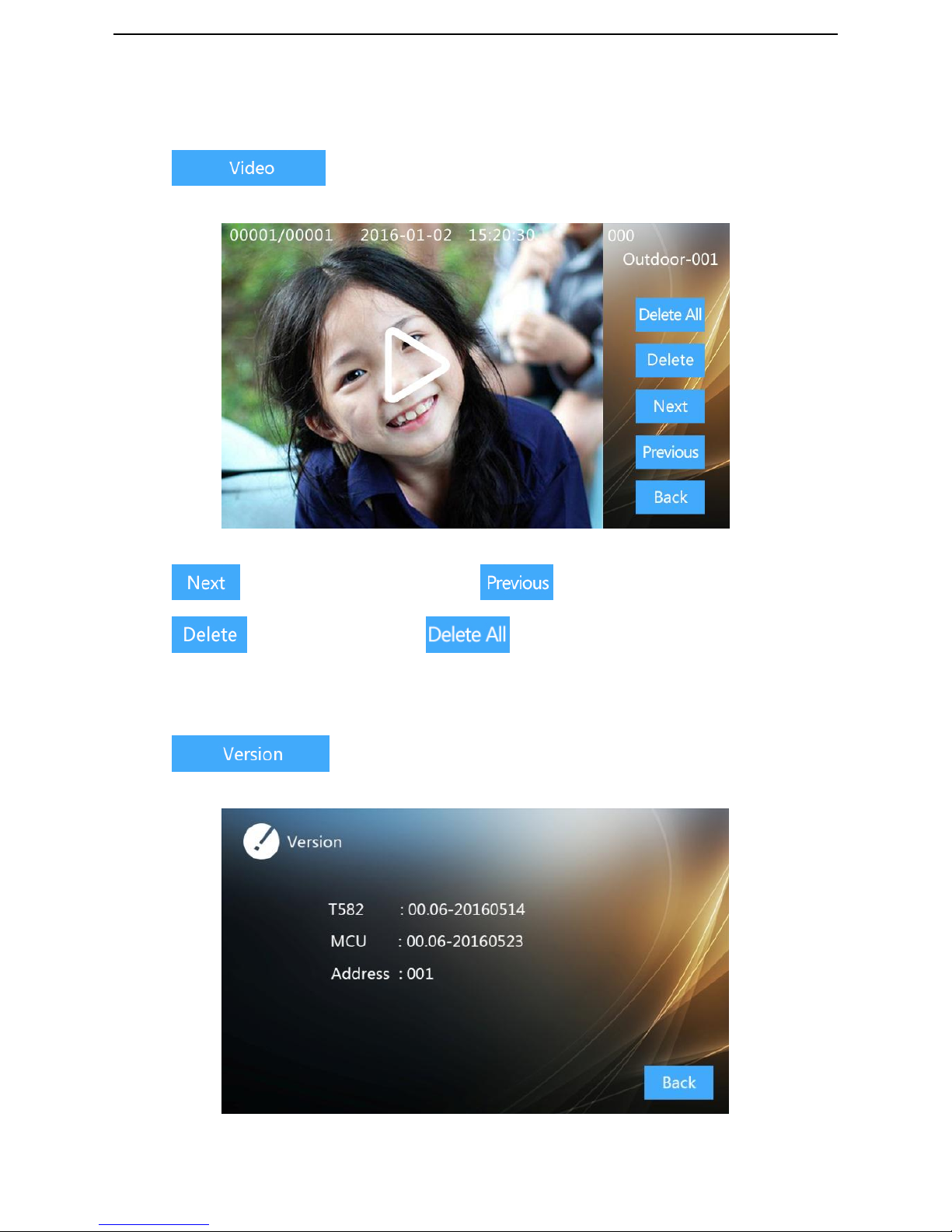
Video
Touch to check the videos.
Video
Touch to select the next video, touch to select the previous one.
Touch to delete vido,touch to delete all photos.
Version
Touch to check the version info,including the MCU and Address.
Version
Page 29
25
Indoor Station Setting
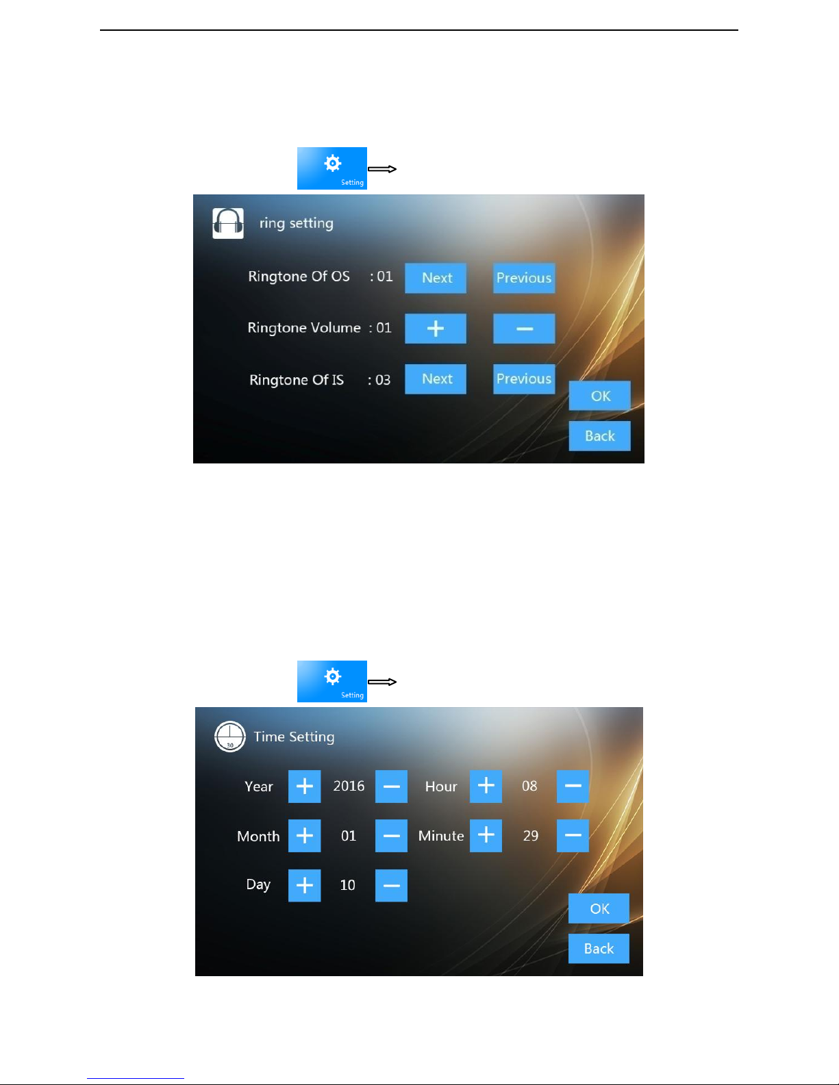
Ring Setting
On the main interface, touch ring setting:
Ring setting
Ringtone Of OS: to set the ringtone of outdoor station or indoor station;
Ringtone Volume: to set the ringtone volume of outdoor station or indoor station;
Ringtone Of IS: to set the ringtone of indoor station
Time setting
On the main interface, touch time setting, to set the date and time.
Time Setting
Page 30
26
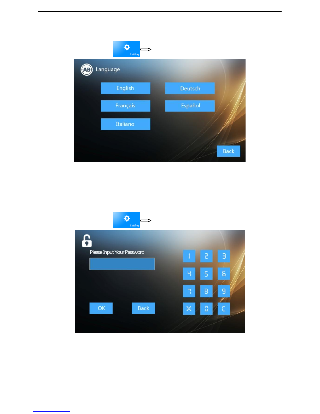
Language setting
On the main interface, touch
Language, to set the language.
Language
It’s a must to set the language when the device is started at 1st time.
Advanced Setup
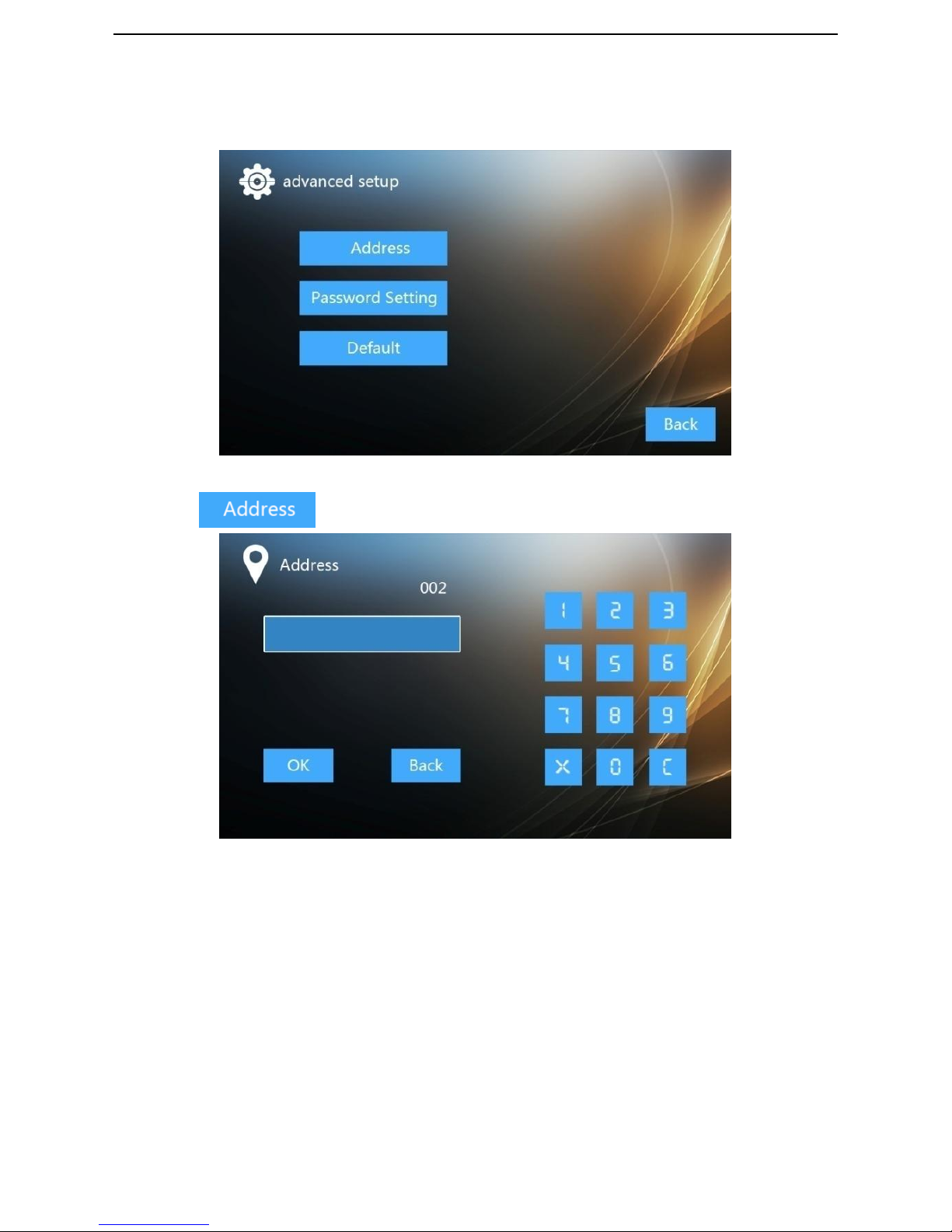
On the main interface, touch Advanced setup,input the password to enter
Password
Note1:
Original password: 123456
Page 31
27
Address Settings
高级设置界面
Touch the and set the address.
Address
Note:
A. Address should be the number of 1 to 100
B. The address of indoor stations in one house should be the same.
Page 32
28
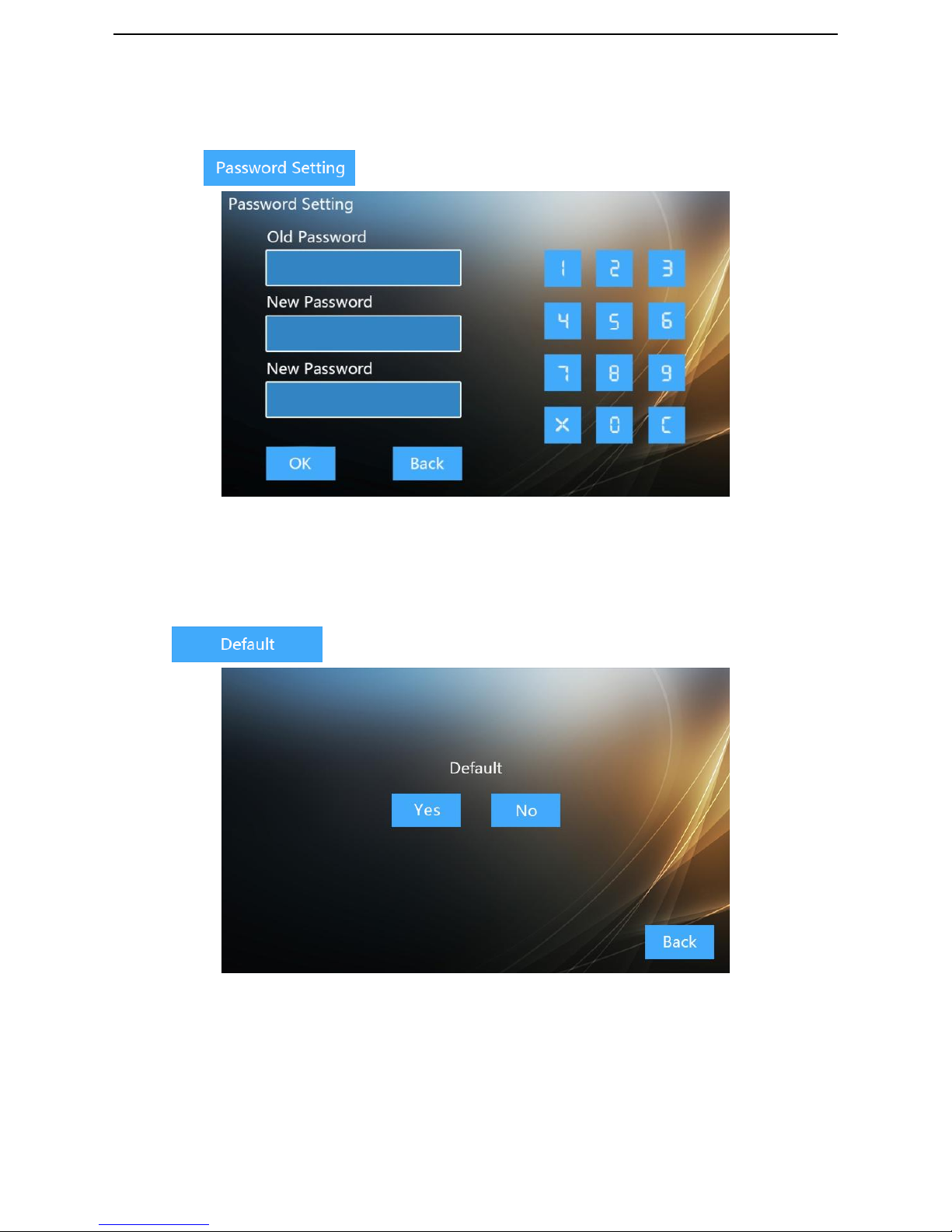
Password Setting
Touch the and set the password.
Password
Input the Old password and the new password to confirm
Default Setting
Touch and “Yes” to reset the device.
Default
Page 33

29
Outdoor Station Settings
Default Setting
Cut off the power of outdoor station, and restart it; The outdoor station ADD is 0, long touch
any key for 3s, it will long ring after setting successfully.
Register Card Settings
Register Admin Card
After the outdoor station reset, the first card to swipe will be the Admin card, it will long ring
after setting successfully.
Continuously Register User Card
In standby mode, swipe the Admin card to enter the Register User Card Mode and it rings once.
Within 15s’ time, user can register User Card. It will long ring and re-time again after success.
When it’s over 15s or fail to register, it will keep ringing and return to standby mode
automatically; After registration, swipe the Admin card again to return to standby mode.
Continuously Delete User Card
In standby mode, swipe the Admin card twice to enter the Delete User Card Mode and it rings
twice. Within 15s’ time, user can swipe to delete User Card. It will long ring and re-time again
after success. When it’s over 15s or fail to delete, it will keep ringing and return to standby
mode automatically; After delete, swipe the Admin card again to return to standby mode.
Continuously Register Admin Card
In standby mode, swipe the Admin card 3 times to enter the Register Admin Card Mode and it
rings 3 times. Within 15s’ time, user can register Admin Card. It will long ring and re-time again
after success. When it’s over 15s or fail to register, it will keep ringing and return to standby
mode automatically; After registration, swipe the Admin card again to return to standby mode.
Continuously Delete Admin Card
In standby mode, swipe the Admin card 4 times to enter the Delete Admin Card Mode and it
rings 4 times. Within 15s’ time, user can swipe to delete Admin Card. It will long ring and
re-time again after success. When it’s over 15s or fail to delete, it will keep ringing and return to
standby mode automatically; After delete, swipe the Admin card again to return to standby
mode.
Page 34
30
Clear User Card
In standby mode, swipe the Admin card 5 times to enter the Clear User Card Mode and it rings
10 times. Within 15s’ time, it will delete all user cards. It will long ring after success. When it
fails to delete, it will keep ringing and return to standby mode automatically; After delete, swipe
the Admin card again to return to standby mode.
Note:
Admin card+User card≤200
张。
Unlock time setting
There’s an adjustable potentiometer on the back side of outdoor station (②), for setting the
unlocking time wihtin 180°; Within 1s ~10s’ time,clockwise ratate to longthen, anticlockwise
rotate to shorten.
ADD Setting
There’s one 2 bits dialer (③),the method to set is as below:
1 2 ADD
OFF
OFF
0
ON
OFF
1
OFF
ON
2
ON
ON
3
Note:
It enters to setting mode when ADD is 0.
Page 35
31
Installation
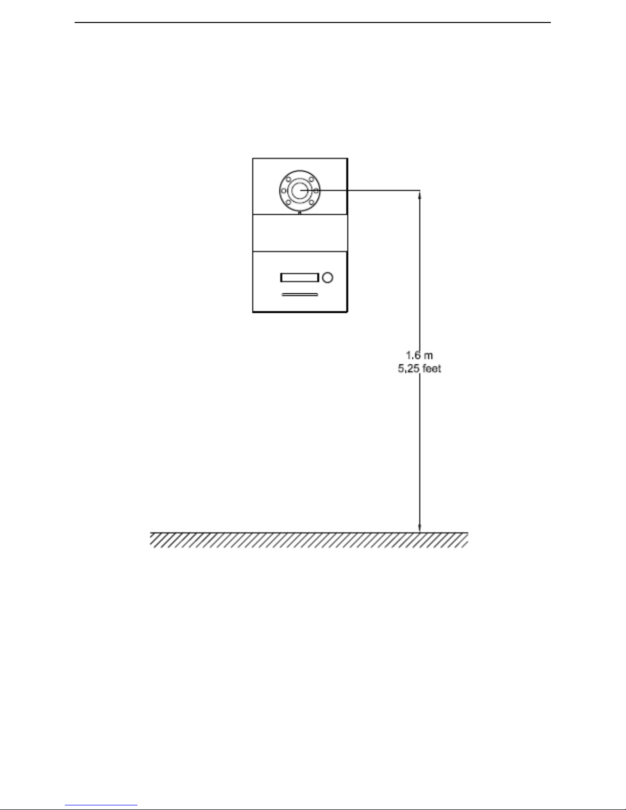
Where to install the outdoor station:
Suggesting height of installation:1.6m
Page 36
32
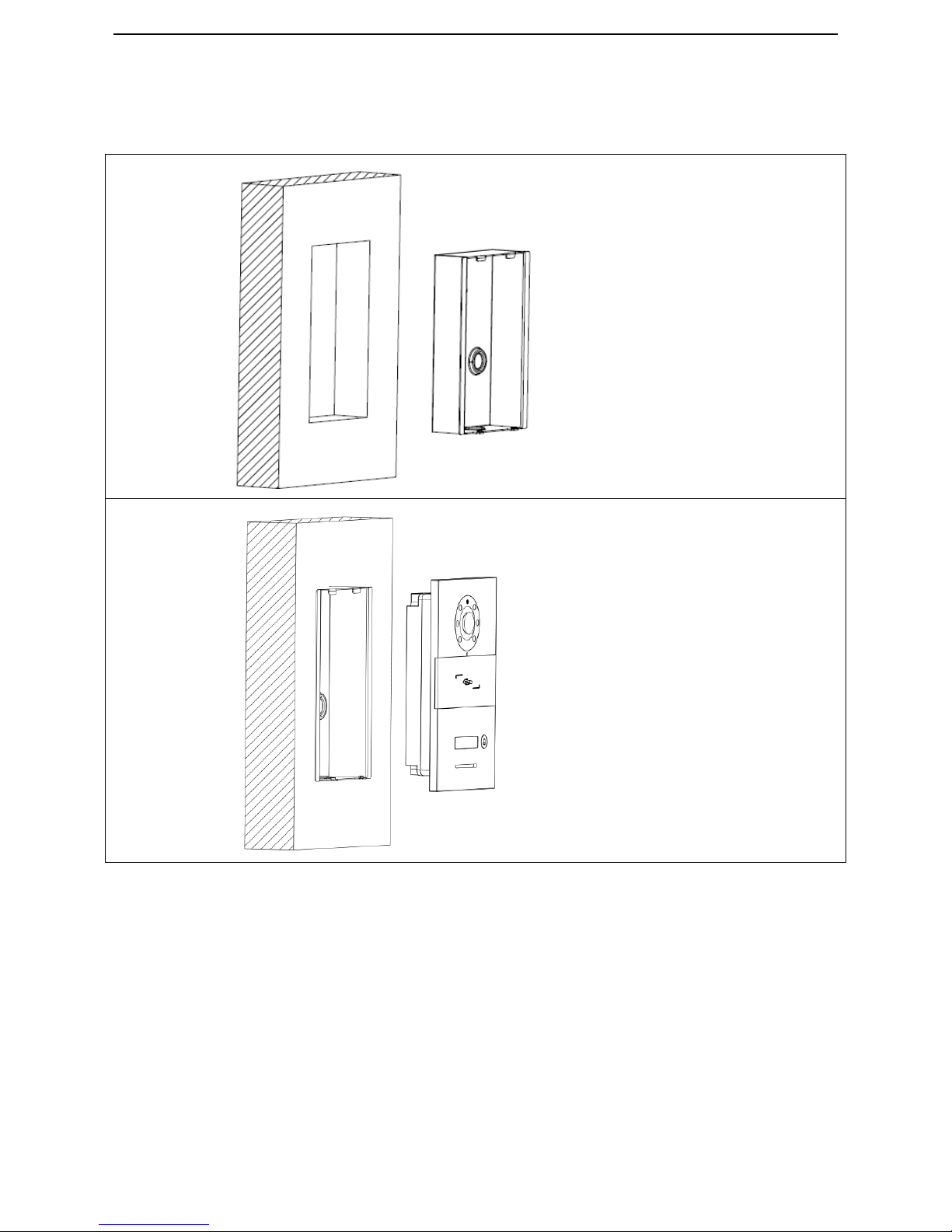
How to install outdoor station:
Step 1:Install the
wall-in box,
installation
dimension
(W/H/D)
100 * 180 *40mm
Step 2:Put the
outdoor station
into the wall-in
box, and fix it with
screw.
Page 37
33
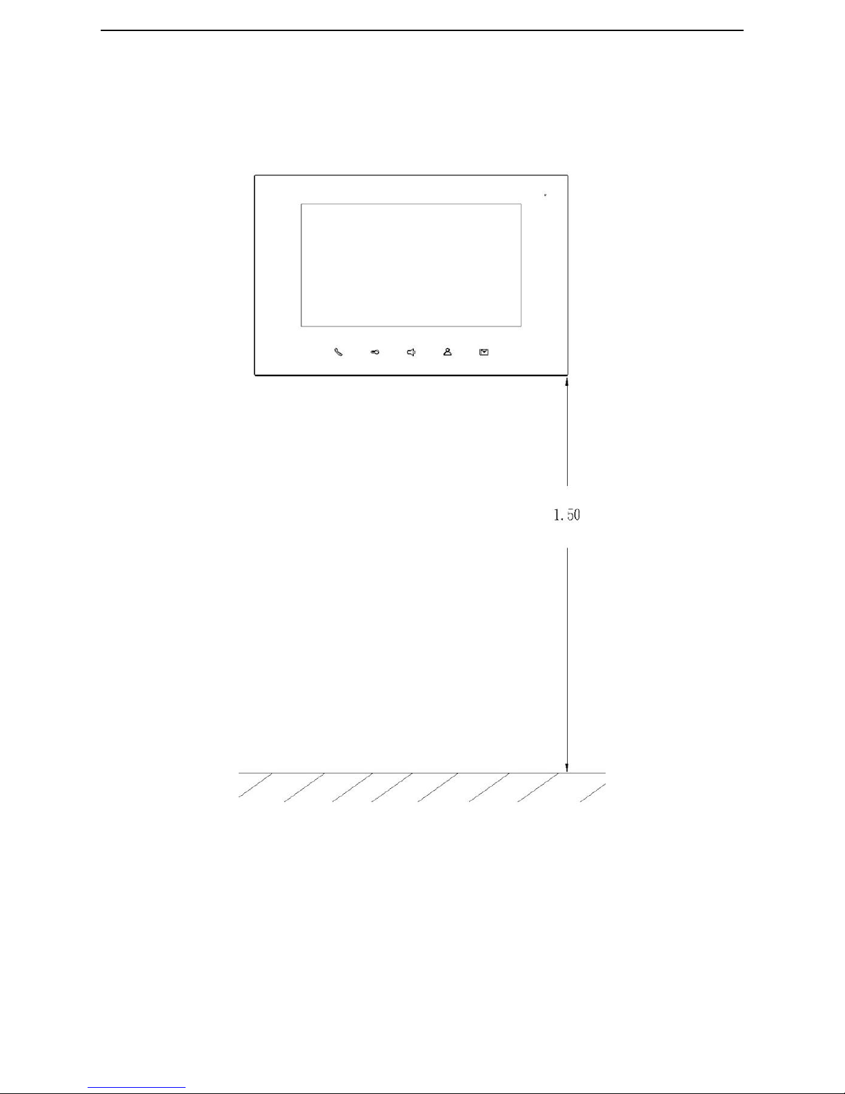
Where to install the indoor station
Suggesting height of installation:1.5m
m
Page 38
34
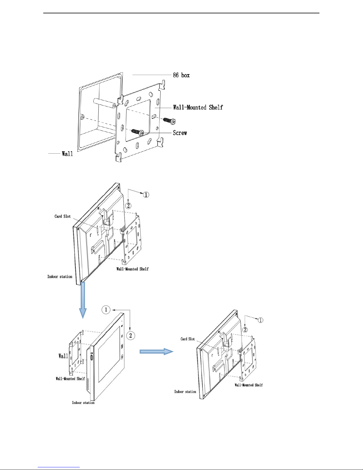
How to install indoor station:
Step 1:Aim
the screw hold
of bracket with
the holes of 86
box. Tighten
the screw and
fix the bracket
Step 2:Connect the indoor
station with wire, and aim the
slot with the hanger of bracket.
Then, move down the device a
little bit. It’s fixed when hearing
“Ka ta”.
Page 39
35
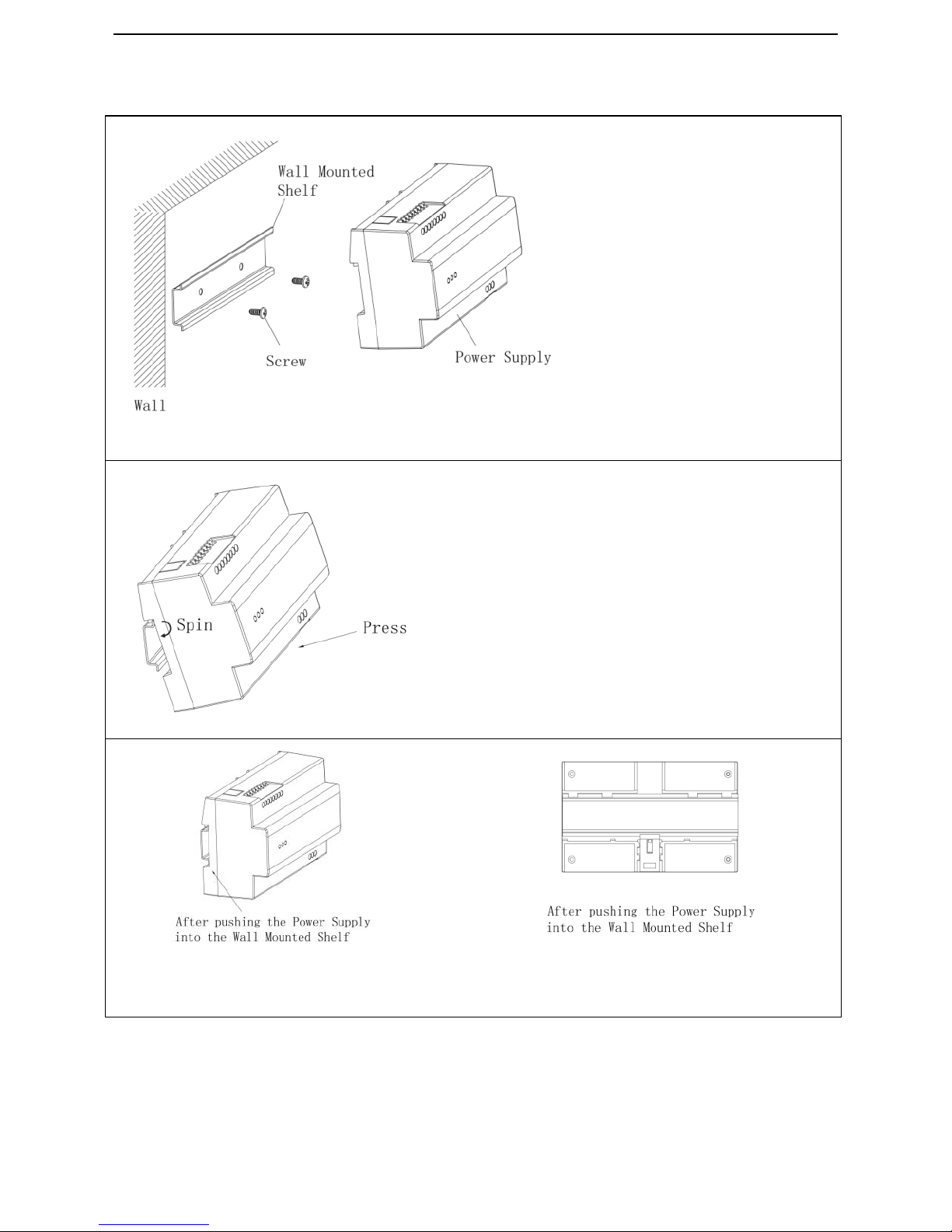
How to install the power supply
第一步
Step 1: Install the
holding bracket and Tighten the
screw and fix the bracket.
Step 2:Aim the power supply
box to bracket, and insert the
fixing slot first, then spin the
power supply and press till you
hear the “Ka ta”.
 Loading...