

Page 1
Gu Guangzhou Video-star Electronics Industrial Co., Ltd
R
K-BUS
○
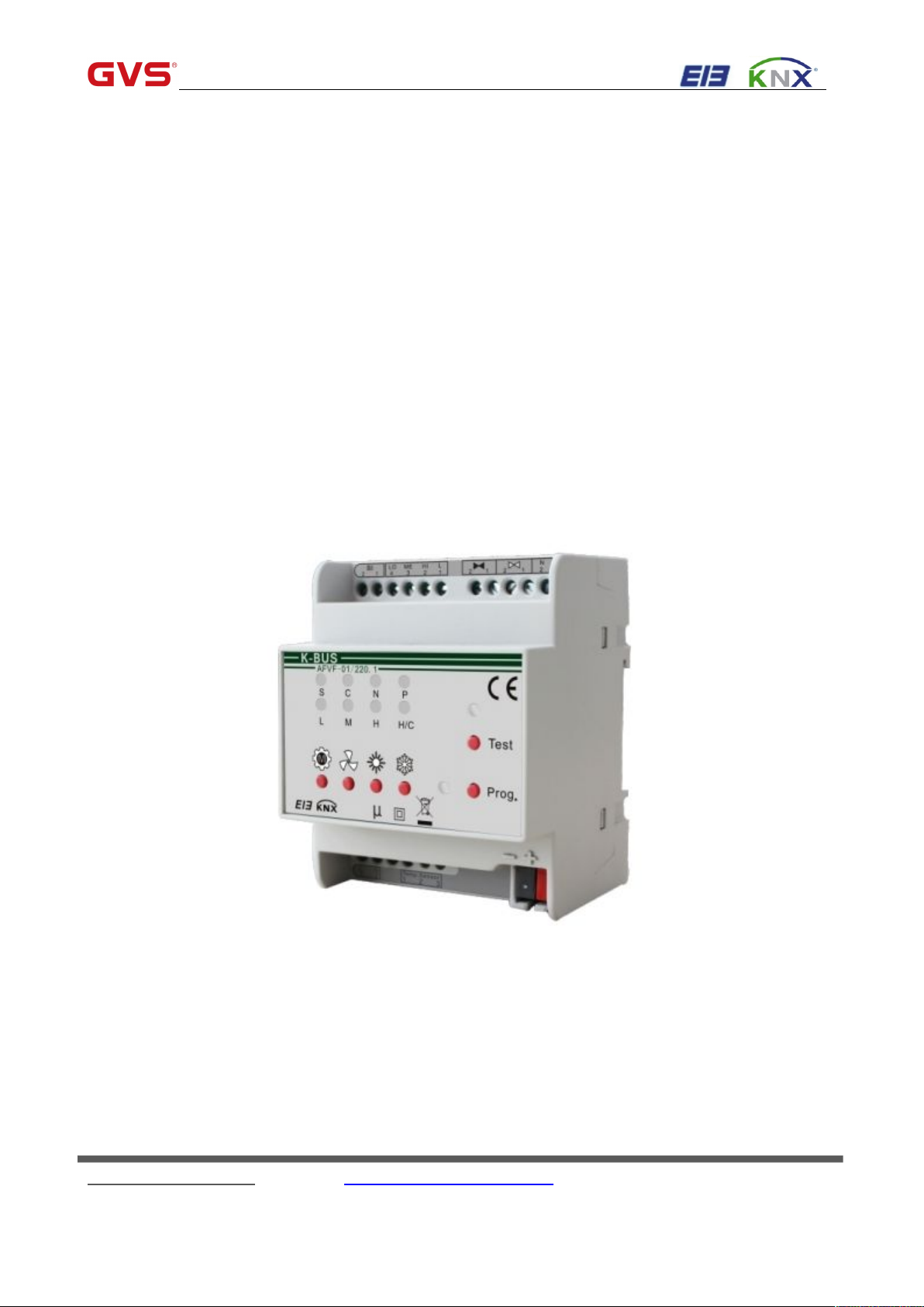
Fan Coil Controller
User manual-Ver. 1
AFVF-01/220.1
KNX/EIB Intelligent Installation Systems
Fax:(8620)39338465
Page 2
GVS K-BUS
Contents
○
R
KNX/EIB Fan Coil Controller
1. Overview
1.1Products and Function Overview
2. Technical Data, Dimension and Circuit Diagram
2.1 Technical Data
2.2 Dimensional Drawing
2.3Wiring Diagram (Taking Continuous Valve for Example)
3. Project Design and Application
3.1 General Introduction
3.2 System Mode and Button Operation Introduction
3.3 Coil System
3.4 Fan System
3.5 Room Temperature Control Mode and Setting Temperature Adjustment
3.6 Type of control
4. ETS System Parameter Setting Description
4.1 Outline
4.2 Parameter window “General”
4.3 Parameter window: “Temperature setting”
4.4 Parameter window "Setpoints"
4.5 Parameter window "Controller"
4.6 Parameter window "Fan"
4.7 Parameter window “heating valve” and “cooling valve’
4.8 Parameter window "Window contact"
4.9 Parameter window "Temperature monitoring"
4.10 Parameter window “Scene”
4.11 External control parameter setting interface
-----------------------------------------------------------------------------------------------------------------------------------
--------------------------------------------------------------------------------------------------
-----------------------------------------------------------------------------------
------------------------------------------------------------------------------------------------------------------------
---------------------------------------------------------------------------------------------------------------
--------------------------------------------------------------------
--------------------------------------------------------------------------------------------------------
-----------------------------------------------------------------------------------------------------------------
-----------------------------------------------------------------------------
---------------------------------------------------------------------------------------------------------------------------
----------------------------------------------------------------------------------------------------------------------------
----------------------------------------------------------------------------------------------------------------------
----------------------------------------------------------------------------------------
--------------------------------------------------------------------------------------------------------------------------------
----------------------------------------------------------------------------------------------------
------------------------------------------------------------------------------------
---------------------------------------------------------------------------------------------------
-------------------------------------------------------------------------------------------------
----------------------------------------------------------------------------------------------------------
--------------------------------------------------------------------
------------------------------------------------------------------------------------------
--------------------------------------------------------------------------------
-----------------------------------------------------------------------------------------------------
---------------------------------------------------------------------------------
--------------------------------------------------
2
3
4
4
5
6
7
7
7
8
8
9
10
11
11
12
15
19
22
24
28
34
36
39
41
5. Description of the communication objects
----------------------------------------------------------------------------------------
1. Overview
Fax:(8620)39338465
45
2
Page 3
GVS K-BUS
This manual provides detailed technical information about the Fan Coil Controller for users as well as
assembly and programming details, and explains how to use the Fan Coil Controller by the application examples.
To achieve convenient installation in distribution box, the Fan Coil Controller is designed to a modular installation
device, and is installed on 35mm DIN Rail according to EN 60 715. It adopts screw terminal to achieve electrical
connection. The connection to EIB/KNX BUS is established via EIB connecting terminal. It requires a 230V AC
power supply.
The Fan Coil Controller can be connected to other EIB/KNX devices to make up the system via EIB/KNX
BUS.
1.1Products and Function Overview
The Fan Coil Controller can work after connecting 230V AC voltage input and bus power supply directly,
without extra power. The parts of valve need voltage input of 75V~265V AC according to demands. It is able to
use the Engineering Tool Software ETS (ETS3 or later) with a VD4 file to allocate the physical address and set
the parameters.
The Fan Coil Controller outputs heating and cooling according to temperature’s setting, and the max. load
current of valve output is 2A. There are 3 levels of fan speeds, and max. load current of each level reaches 6A.
Both valves of heating and cooling and fan speeds can be switched on or off by manual buttons, and their status
are shown by LED.
The functions of the Fan Coil Controller are shown as follows:
Output heating and cooling according to temperature’s setting
Output modes of Standby, Comfort, Night and Protection according to user’s demands.
Control fan speeds in 3 gears (High, Medium, and Low) manually or automatically.
Control the raise/lower valves and ordinary switching valves intelligently and manually.
Achieve continuous or PWM output control for valves by PI controlling value.
Report local fan speeds and valves’ status.
Obtain temperature data from local or BUS, and achieve the monitoring function to actual temperature and
frost temperature.
Scene control, output specific operation mode and speed directly via recall scene.
Detect shutter’s on-off status or binary input.
Achieve the controlling by external controller ( e.g. via the Panel of Temperature Controller )
○
R
KNX/EIB Fan Coil Controller
Fax:(8620)39338465
3
Page 4

R
Fan Coil Controller is a modular installation device, and installed on 35mm DIN Rail in distributor box. It is
connected EIB/KNX system via BUS connecting terminal.
2.1 Technical Data
Power Supply
Bus voltage
21-30V DC, via the EIB bus
Current consumption, bus
<12mA
Power consumption, bus
<360mW
Input Voltage
230 V AC +/-10%(50/60Hz)
Total Power Consumption
1.4W
Control of Heating/Cooling
2 folds Valve Control
Raise/lower valve and thermal valve can be
connected. One fold for heating, the other for
cooling.
Nominal Voltage
75V~265V AC (220VAC or 110VAC Motor)
Nominal Current
2A
Cable Length
Max. 20m (cross-sectional: 1-1.5mm2)
Fan Control
1 fold Fan
3 level fan speeds
Nominal Voltage
230V~(50/60Hz)
Nominal Current
6A
Note:In the case that above 3 level speeds are used as independent switching
outputs, the max. Current of each output 6 A, and the total of 3 outputs
cannot exceed 13A.
Binary Input
1 fold
For shutter’s on/off status and binary input
input Voltage
9V~265V AC/DC
Cable Length
Max. 100m (cross-sectional:1- 1.5mm2)
Tem. Measurement
Three-wire system PT1000 Tem.
Sensor
It is used to detect room temperature
Measuring Scope of Tem.
– 45°C ... + 80°C
Cable Length
2m
Buttons and Indicator LEDs
Fan Gears
1 button and 3 green LED
Operation modes
1 button and 4 red LED
GVS K-BUS
○
KNX/EIB Fan Coil Controller
2. Technical Data, Dimension and Circuit Diagram
4
Fax:(8620)39338465
Page 5
GVS K-BUS
Heating/cooling
2button and 1 red & blue LED
Programming
1buton and 1 red & green LED
Please refer to section 2.3 for location of Button and Indicator LED, and 3.2
for operation description
Temperature rang
Operation
-5℃ ... + 45 ℃
Storage
-25℃ ... + 55℃
Transport
-25℃ ... + 70℃
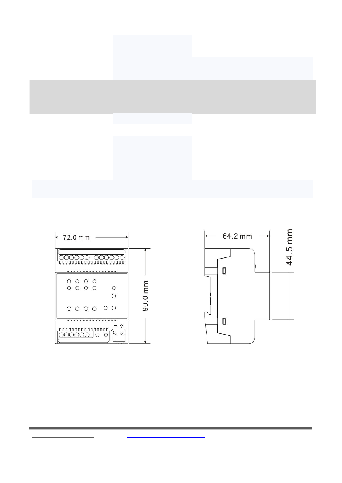
Dimensions
90 x 72 x 64.2 mm
Installation
On 35mm DIN Rail, and on clean, dry indoor places
Safety class
-II
to EN61140
Electronic control
Type1.B
To EN 60730-1
Weight
0.3kg
Color
Grey
2.2 Dimensional Drawing
○
R
KNX/EIB Fan Coil Controller
5
Fax:(8620)39338465
Page 6
GVS K-BUS
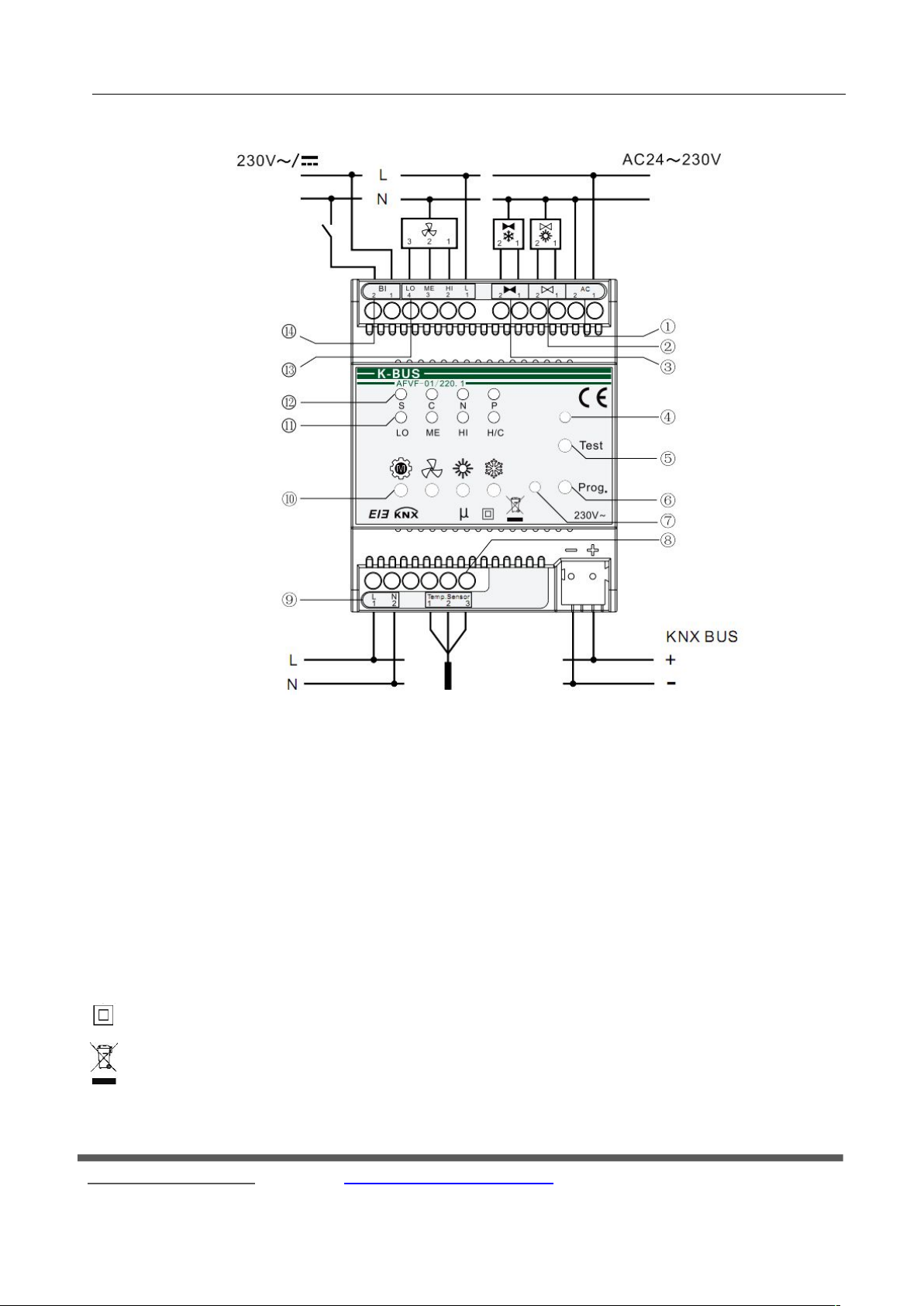
2.3Wiring Diagram (Taking Continuous Valve for Example)
①Power supply for valve
⑧ Temperature sensor input
② Heating Valve (1-close, 2-open)
⑨ Power supply 230V AC
③ Cooling Valve (1-close, 2-open)
⑩ manual buttons, from left to right: operation modes,
Fan speeds, Heating and Cooling
④ Control Mode Indicator LED
⑪ Indicators of Fan speed (LO-Low, Me- Medium, and
HI-High) and Heating/Cooling
⑤ Testing Button
⑫ Indicators of Room operation Mode: S- Standby, C-
Comfort, N-Night, P-Protection
⑥ Programming Button
⑬ output 3 fan speeds: LO, ME , HI
⑦ Programming LED
⑭ Binary Input
μThis symbol indicates Micro-disconnection on operation, Type 1.B
○
R
KNX/EIB Fan Coil Controller
This symbol indicates Class II
This symbol indicates separate collection for electrical and Electronic equipments.
6
Fax:(8620)39338465
Page 7
GVS K-BUS
3. Project Design and Application
3.1 General Introduction
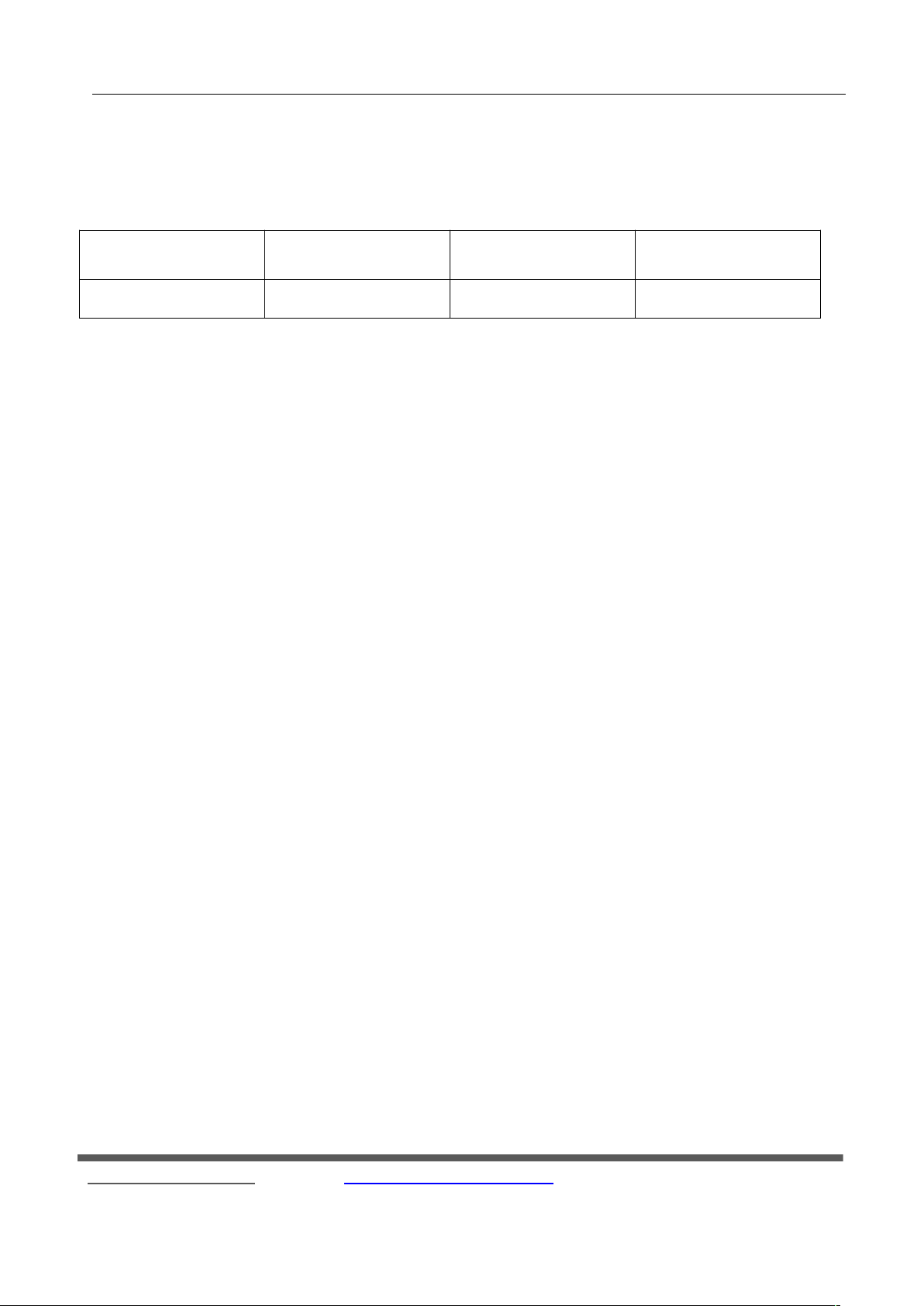
Application Program
Max. number of
Communication Objects
Max. number of
Group Addresses
Max. number of
Associations
Fan coil Controller
385050
The Fan Coil Controller controls Fan’s fan speeds and Valve’s opening degree intelligently by PI Algorithm,
and achieve heating/cooling to make rooms comfortable through comparison between setting temperature and
actual temperature. The Fan Coil Controller contains 1 fold temperature data collection, 1 fold binary input, 1 fold
Fan control and 2 folds Valve control.
3.2 System Mode and Button Operation Introduction
The Fan Coil Controller has 3 control modes: Automatic Control Mode, Manual Control Mode and Testing
Control Mode.
Automatic Control Mode: When testing/auto indicator light is off, the mode is automatic control. In this mode,
Fan Coil’s output is controlled via the Fan Coil Controller, and the mode can be switched to testing or manual
control mode, as well as room operation modes can also be switched by manual button.
Manual Control Mode: When testing/auto indicator light is on, the mode is manual control. The manual control
mode can be activated via recalling scene (Object 12) or controlling fan speed manually (Object 15), and be
returned to the automatic control mode via setting Object 16 to 1. The Manual control mode refers to adjusting
Fan’s fan speed via KNX telegram (Note: this mode is for Fan only, the Valve is still controlled automatically). In
this mode, room operation modes can be switched by manual button, and the control mode only can be switched to
the Automatic Control Mode.
Testing Control Mode: When testing/auto indicator light is flashing, the mode is testing control. The mode can
be activated or returned to automatic control mode via pressing testing button for 2s. In this mode, output of valves
can be controlled via heating button and cooling button. Besides, for local continuous raise/lower valve the
controller can control it pause via pressing heating or cooling button for 2s and the heating/ cooling indicator would
flash. The pause function can be exited via a short operation of the button. The Fan speeds can be adjusted via
○
R
KNX/EIB Fan Coil Controller
7
Fax:(8620)39338465
Page 8
R
fan-speed button; the fan-speed gear is change via a short operation, the current speed is switched on or off via a
long operation, and the corresponding indicators would on or off. In this mode, room operation modes cannot be
changed, and the control mode only can be returned to the Automatic Control Mode.
3.3 Coil System
3.4 Fan System
GVS K-BUS
Fan Coil can be designed as 2-pipe, 3-pipe, or 4-pipe version, according to hot and cold water’s circulation
loops.
The 2-pipe version consists of a single water circulation loop for both hot and cold water. It is achieved only
by connecting one fold valve to control flow of hot and cold water, and the default connecting is heating output. In
lots of practical application, only cooling is carried out via a 2-pipe fan coil, and heating is implemented by other
conventional heaters.
The 3-pipe and 4-pipe versions are quite similar to each other. For 3-pipe version, the hot and cold water have
separate inlet, while they share one outlet. The 4-pipe version has separate water circulation loops for both hot and
○
KNX/EIB Fan Coil Controller
cold water. For both 3-pipe and 4-pipe, hot and cold water’s flow can be controlled by connecting to Fan Coil
Controller’s control terminal of heating and cooling valve.
Valve has two types: Raise/ lower valve and Thermal valve. Raise/ lower valve control valve’s opening
according to its run time, to achieve status of on, off and pause. It is 3-wire system, shown as wiring diagram.
Thermal valve is usually divided to normally open type and normally closed type, and has only two statuses: on/off.
It is 2-wire system, and one for valve’s open (as wiring diagram ②and ③ of 2 shown), the other for null line of
valve power supply ( as wiring diagram ① of 2 ) .
Fan system can control local Fan, as well external Fan, and it is achieved via parameter setting of “Type of
fan”
Fan can be controlled both automatically and manually. Auto control is Fan Coil’s control according to
algorithm output. Manual control is used to adjust current fan speed according to KNX telegram. Under manual
control, Fan cannot be controlled by Fan Coil, unless the mode is auto control.
Auto-control Fan adopts stepping sequence, that is, the fan speed can be adjusted step by step only, but not
phase step. For example, to change current gear 0 to 3, the operation order is 1->2->3, and between each two gears,
it would stay at least 2mins due to the parameter “Minimum delay at fan speed”. The limitation is un available
when it is manual mode or testing mode.
Fax:(8620)39338465
8
Page 9
R
3.5 Room Temperature Control Mode and Setting Temperature Adjustment
GVS K-BUS
Room Temperature Control Mode
Room temperature control has 4 modes: comfort mode, standby mode, night mode, and protection mode,
and it is used to adjust rooms’ setting temperature, and it can be switched via KNX BUS or room mode button.
Via KNX BUS, to select a 1byte communication object or three 1bit objects can help to switch room modes.
When selecting three 1bit objects as above-mentioned, the objects have priority as follows: protection
mode >comfort mode > night mode > standby mode. Writing “1” on the relevant object enables room mode, and
writing “0” disable it. When lower priority would replace the higher priority, close the latter first. When object 9,
object 10 and object 11 are “0”, the mode is lowest priority – standby mode.
When selecting a 1byte to switch to room mode, value 0: stay; value 1-4 represent comfort mode, standby
mode, night mode, and protection mode respectively; value 5-255, invalid.
○
KNX/EIB Fan Coil Controller
Setpoint values
Setpoint value is configured in the parameter window “Setpoints”.
Setpoint temperature of actual output can be calculated according to following:
Comfort mode: Heating: Setpoint temperature = Base setpoint temperature + Setpoint adjustment
Cooling: Setpoint temperature = Base setpoint temperature + Setpoint adjustment + Insensitive
zone + external temperature correction ( Pls refer to “External temperature” in the
parameter window “Temperature setting ” under cooling control )
Standby mode: Heating: Setpoint temperature = Base setpoint temperature – Reduces heating in standby mode +
Setpoint adjustment;
Cooling: Setpoint temperature = Base setpoint temperature + Increased cooling in standby
mode + Setpoint adjustment
Night mode: Heating: Setpoint temperature = Base setpoint temperature –Reduces heating in night mode +
Setpoint adjustment;
Cooling: Setpoint temperature = Base setpoint temperature + Increased cooling in night mode +
Fax:(8620)39338465
9
Page 10
R
3.6 Type of control
GVS K-BUS
○
KNX/EIB Fan Coil Controller
Setpoint adjustment
Protection mode: Heating: Setpoint temperature = Threshold value for heat protection
Cooling: Setpoint temperature = Threshold value for frost protection
Setpoint adjustment is realized via object 5.
Note: When user chooses “Heating and cooling ” of “Controller mode in Heating/Cooling” in the
parameter window “General”, auto control to toggle heating and cooling is related to setting temperature
in comfort mode only, that is, the comparison between setting temperature and actual temperature
generate heating or cooling.
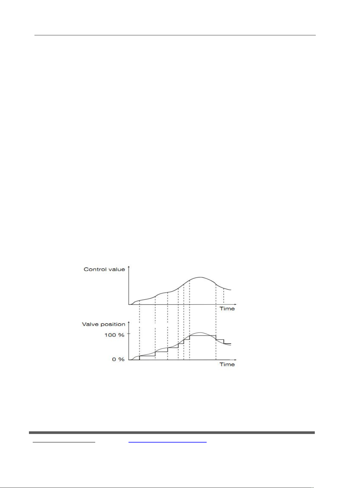
Continuous control
Continuous control is based on the actual temperature and set the thermometer calculates a control value, and the
valve opening degree of the continuous control, the temperature to achieve a comfortable condition. For example: the
current control value is the maximum 50% of the control value , then the valve position will be under the control value to
50% open position ; If the control value output to the maximum control value , the valve will be fully open. Continuous
control can be achieved "on" and "off” and “stop" three-step operation, the specific action as shown below:
Continuous control, can achieve the most accurate temperature control, no considerable overshoot. Meanwhile, the
positioning of the valve drive frequency can be maintained at a low level. Continuous control
can be used with the Fan
Coil Controller for electromotive raise/lower valves or KNX valve drives.
Fax:(8620)39338465
10
Page 11
R
4.1 Outline
Fan coil controller either as a master device can also be used as the controlled device.
GVS K-BUS
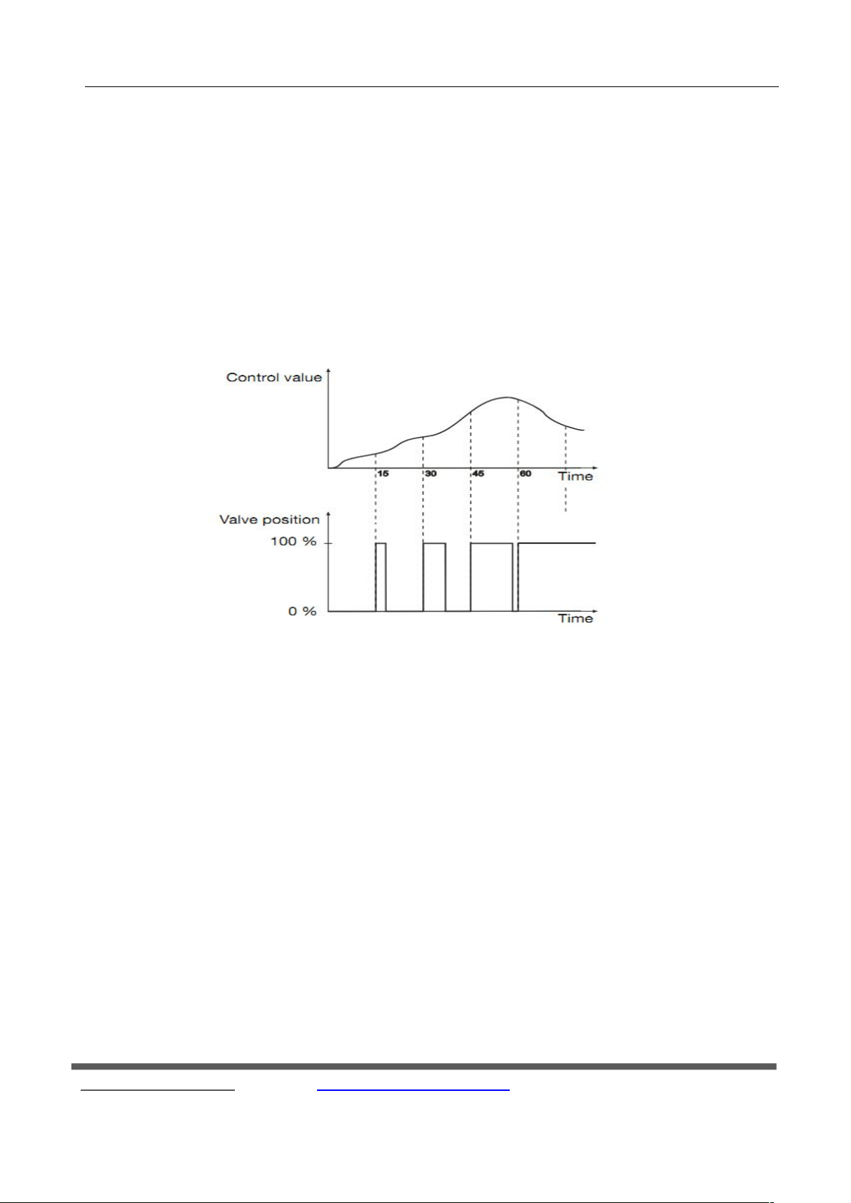
PWM control
PWM (pulse width modulation) control is based on the actual temperature and set the thermometer calculates a
control value, and then calculates the valve opening and closing time of the switch valve is controlled to achieve a
comfortable temperature state. On/off valve that only “full open" and “fully closed” two kinds of control operations.
PWM control need to set a fixed cycle time period, For example, set the PWM period of 15 minutes, when the control
value is the maximum 20% of the control value, the valve will open 15 * 20 % = 3 minutes; Off 15 * 80 % = 12 minutes;
when the control value is the maximum control value of 50 %, the valve will open 15 * 50 % = 7.5 minutes; off 15 * 50
% = 7.5 minutes. Diagram is as follows:
○
KNX/EIB Fan Coil Controller
PWM control is a relatively accurate adjustment, if you select the appropriate cycle, temperature overshoot will not
be great, and you can use a simple low cost general switching valve actuator. Fan coil can be used to control the common
switching valve, electric valve or KNX valve drives.
4. ETS System Parameter Setting Description
1. Local(master device)
Local control fan coil controller acts as the master role, which according to the set temperature and the actual
temperature difference to calculate the control value, thus control the valve and the speed. In this mode, the local
wind speed and valve can be controlled by own, or via bus fan speed and valve of the external fan coil can be also
controlled.
11
Fax:(8620)39338465
Page 12
R
4.2 Parameter window “General”
Parameter: Controller from
Options: Local
Bus
This parameter sets the fan coil controller source. Wind speed and valve of fan coil controller can be locally
controlled by an internal controller (the connected temperature sensor in the input), can also be controlled via bus
(such as temperature panel).
“Local” shows that the outputs of the fan coil controller are controlled by the internal controller, i.e. as the
master device. In this mode, the fan coil controller can either control the local wind speed and valve, or can also
GVS K-BUS
2. Bus (controlled device)
As controlled by the external control fan coil controller role, and its temperature is not monitored and does
not output the control value, but by an external controller (e.g., temperature and humidity sensors, temperature
control panel, etc.) is sent to the control value for the output control. In this mode, the control value from external
only can control the fan coil local control valve and speed controller.
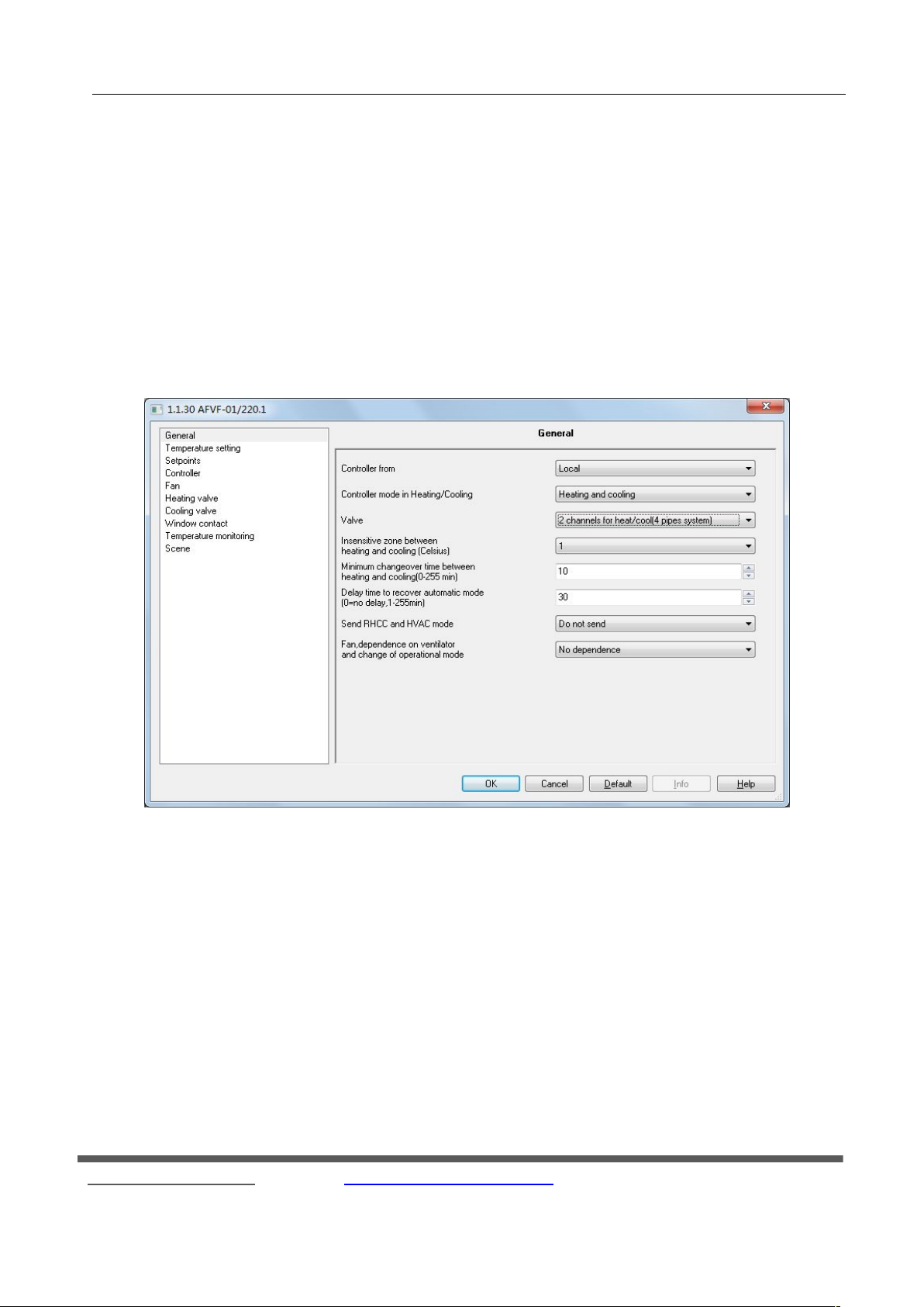
"General" parameter setting interface shown in Figure 4.2, this parameter setting window is mainly set some
basic parameters of fan coil controller. Intro of each parameter follows.
○
KNX/EIB Fan Coil Controller
Fig.4.2 parameter window “General”
Fax:(8620)39338465
12
Page 13
GVS K-BUS
control the wind speed and valve of external fan coil controller via bus.
"Bus" shows that the fan coil controller is controlled by an external controller, i.e. as the controlled device; in
this mode, the outputs of the fan coil controller are controlled via bus.
Since the sources are not the same, so their parameter settings are also not the same, we then introduce "Local"
parameter settings, "Bus" in case of parameter settings to 4.11 do detail.
Parameter:Controller mode in Heating/Cooling
Options: Heating
Cooling
Heating and cooling
This parameter sets the HVAC heating and cooling.
Select the "Heating", controller is in heating control state, then fan coil only achieved heating function;
Select "Cooling", controller is in cooling mode, the cursor can only achieve cooling,
If select "Heating and cooling", both heating and cooling can be achieved, fan coil controller outputs
automatically heating or cooling according to the set temperature and the actual temperature difference and the dead
zone. Meantime, the corresponding parameters will be visible.
Parameter:Valve
Options: 1 channel for heat/cool(2 pipes system)
2 channels for heat/cool(4 pipes system)
This parameter sets the water pipe type of fan coil.
"1 channels for heat / cool (2 pipes system)" for the heating and cooling shared an inlet and outlet pipe, that is
hot and cold water pipes are out from a pipe. In the case, you only need a valve to connect with heating valve output
of fan coil controller;
"2 channels for heat / cool (4 pipes system)" for the heating and cooling, respectively, have their own pipe to
in and out water, requires two separate control valve to control in and out of hot and cold water.
Parameter:Choose heating or cooling by
Options: Local
Bus
This parameter is visible if the option "1 channels for heat / cool (2 pipes system)" is select in the parameter
"Valve", which is used to set heating or cooling for the 2 pipes system.
With “Bus”, the cooling and heating can be controlled via external input, and the control of cold or hot water
○
R
KNX/EIB Fan Coil Controller
13
Fax:(8620)39338465
Page 14
GVS K-BUS
is realized via the communication object 7 and 8.
"Local" means that the actual temperature and the set of local parameters to determine the output control of
heating or cooling.
Parameter:Insensitive zone between heating and cooling
Options: [°C] 0.5...6.0
This parameter set the dead zone that is used to switch automatically heating and cooling. When the smaller
the value of the dead zone, the faster switching between heating and cooling according to the temperature, but the
heating and cooling frequent exchange; larger values when the dead zone is not so frequent exchange heating and
cooling, energy conservation, but switching heating and cooling of the reaction is slow. Dead zone temperature
usages see 3.5 Introduction. The parameter will be visible in the parameter window "General" of the "Controller
mode in Heating / Cooling" with the option "Heating and cooling".
Parameter:Minimum changeover time between heating and cooling
Options: [min.] 0...255
This parameter sets the minimum pause in minutes when toggling between heating mode and cooling mode.
Mainly prevent frequent switching heating and cooling, and energy conservation.
Parameter:Delay time to recover automatic mode
Options: [min.] 0...255
This parameter set the delay time from the manual or test mode switch back to automatic mode.
With option "0", the controller does not automatically switch back to automatic mode until the user via the
KNX communication objects or local button to switch back to automatic mode;
For "1-255" the manual mode or test mode will switch back to automatic mode after delay.
Parameter:Send RHCC and HVAC status
Options: Do not send
Send on change
Send cyclically
The parameter sets the transmission event for the HVAC and RHCC status.
With "Do not send” two status reports is not sent.
With "Send on change", the status is only sent if there is a change in the object value.
With "Send cyclically”, the object value is sent according to the parameterized period for cyclical sending, but
○
R
KNX/EIB Fan Coil Controller
14
Fax:(8620)39338465
Page 15
GVS K-BUS
also sent when changes.
Parameter:Period of sending fan coil status
Options:[min.] 1…255
This parameter sets the period for cyclical sending the RHCC and HVAC status. This parameter is visible
when the option "Send cyclically" in the parameter "Send RHCC and HVAC status" is selected.
Parameter:Fan,dependence on ventilator and mode change of operational mode
Options: No dependence
Switch fan to automatic on mode change
Switch comfort mode on manual operate fan
This parameter sets the connection between the fan and the operation mode.
"No dependence" indicates no relationship between both of them;
If "Switch fan to automatic on mode change" is selected, and the fan is in manual control (via the object 15),
fan coil control is automatically switched to automatic control mode when the operation mode changes via KNX
telegram.
If "Switch comfort mode on manual operate fan" is selected, and the room of control mode is not comfort
mode, the fan coil control is automatically switched to the comfort mode when the fan speed changes via KNX
telegram (the object 15).
4.3 Parameter window: “Temperature setting”
○
R
KNX/EIB Fan Coil Controller
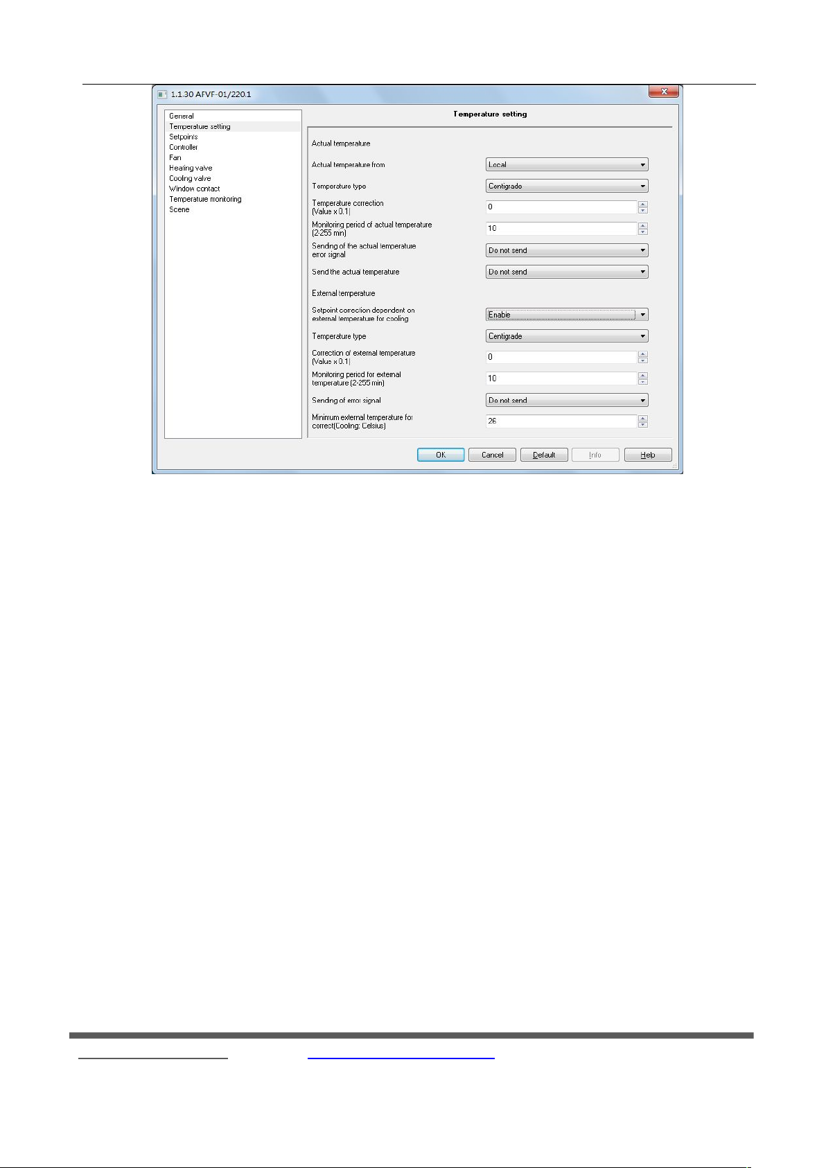
Parameter window "Temperature setting" is shown in Figure 4.3. The window primarily sets the basic
parameters of the temperature. "Actual temperature" and "External temperature" two parts, of which "External
temperature" parameters are visible with the option "Cooling" or "Heating and cooling" in the parameter
"Controller mode in Heating / Cooling" of the "General" parameter window. The following detailed describe
settings of each parameter.
Fax:(8620)39338465
15
Page 16
GVS K-BUS
Actual temperature
Actual temperature, mainly setting the way of collecting temperature, temperature type and correction,
monitoring and sending of the temperation and so on.
Parameter:Actual temperature from
Options: Local
Bus
Setting the temperature sensor.
If the temperature sensor PT1000 is connected to the Fan Coil Controller, the option “Local” must be selected.
If the temperature is received via the KNX, the option “Bus” must be set.
Note: The fan coil controller needs to know the current heating or cooling output clearly to control to work
properly, the heating or cooling can be the actual temperature and the set temperature compared to determine, in
some cases need to clear through the communication objects, such as the two coils control systems and as a
controlled device.
Parameter:Temperature type
Options: Centigrade
Fahrenheit
○
R
KNX/EIB Fan Coil Controller
Fig. 4.3.1 parameter window “Temperature setting”
16
Fax:(8620)39338465
Page 17
GVS K-BUS
This parameter is set to the bus output, or received from the bus type of the actual temperature.
"Centigrade" indicates the actual temperature is expressed in degrees Celsius;
"Fahrenheit" indicates the actual temperature is Fahrenheit.
Wherein the relationship between Fahrenheit and Celsius are as follows: F = 32 + °C × 1.8.
Parameter:Temperature correction
Options: [val x 0.1°C] -50...50
Correction of the value measured by the temperature sensor PT1000 or the actual value received via the KNX.
When the temperature sensor receives the temperature value and the actual value of the parameter deviation
can be corrected. For example: no output before calibration temperature of 25 degrees, but the indoor temperature is
25.5 degrees, then the database where the calibration temperature must be set to 5 ( 0.1 * 5 ), and then re-download
the database, it will have 25.5 degrees output temperature.
Parameter:Monitoring period of actual temperature
Options: [min.] 2...255
Parameter:Sending of error signal
Options: Do not send
Send on change
Send cyclically
This parameter is setting to send the actual temperature of the wrong way.
"Do not send" when an exception occurs for the actual temperature is not transmitted to the bus error status
report;
"Send on change" is the actual temperature of the abnormal state when there is a change on the transmission
error status value, which is only made when actual temperature anomaly a "1" (True means 1), until the actual
○
R
KNX/EIB Fan Coil Controller
Setting the monitoring period for the actual temperature (local and via the KNX).
When the temperature is up from the Bus, then within the set time did not update, then it is wrong temperature,
the corresponding telegram is sent "True"; when the temperature reading from the Local, at this set time has
remained the same a temperature value, it is considered wrong temperature, the corresponding telegram will be sent
"True". Error occurs when the control value output parameter page "Temperature monitoring" parameter "when
actual temperature is absent or in event of frost" setting maximum control value ( 10,000 ) Percentage.
Note: If a sensor value is received via the KNX, the monitoring period should be selected so that it is at
least twice as long as the cyclical transmission period of the sensor so that an error message is not sent
immediately when a signal fails to appear.
17
Fax:(8620)39338465
Page 18
GVS K-BUS
temperature returned to normal hair only a "0" (Flase means 0);
"Send cyclically" send for the cycle, depending on the setting of the transmission time , time to send a
message , but the actual temperature anomalies also sent telegram, and sent at this time to re-cycle timing .
Parameter:Period of sending
Options:[min.] 1…255
This parameter is setting when actual temperature occurs an exception, the controller sends the error status
reporting time period to BUS. This parameter only "Sending of error signal" option to "Send cyclically" is visible.
Parameter:Send the actual temperature
Options: Do not send
Send on change
Send cyclically
This parameter is setting to read from the local pt1000 temperature sensor value and sent to the BUS.
"Do not send" the local acquisition temperature does not occur on the bus made;
"Send on change" for the local temperature changes when a certain value, the controller transport the
temperature value on the bus;
"Send cyclically" Send for the cycle, that is every once in a while to send a temperature value. This parameter
is only "Actual temperature from" option for the "Local" visible.
Parameter:Send temperature at variation of
Options:0.1…5
This parameter is to set the actual temperature variation. When the actual temperature changes every time the
option value, the fan coil controller will be sent to the bus once the actual temperature. This parameter is only "Send
the actual temperature" option to "Send on change" visible.
Parameter:Time lag of sending actual temperature
Options: [min.] 1…255
This parameter is set to send the local actual temperature period time. This parameter is only "Send the actual
temperature" option to "Send cyclically" visible.
External temperature
External temperature only in the case of a cooling occurs , the parameter item in the "General" parameter page
"Controller mode in Heating / Cooling" is selected for "Cooling" or "Heating and cooling" is visible . Mainly used
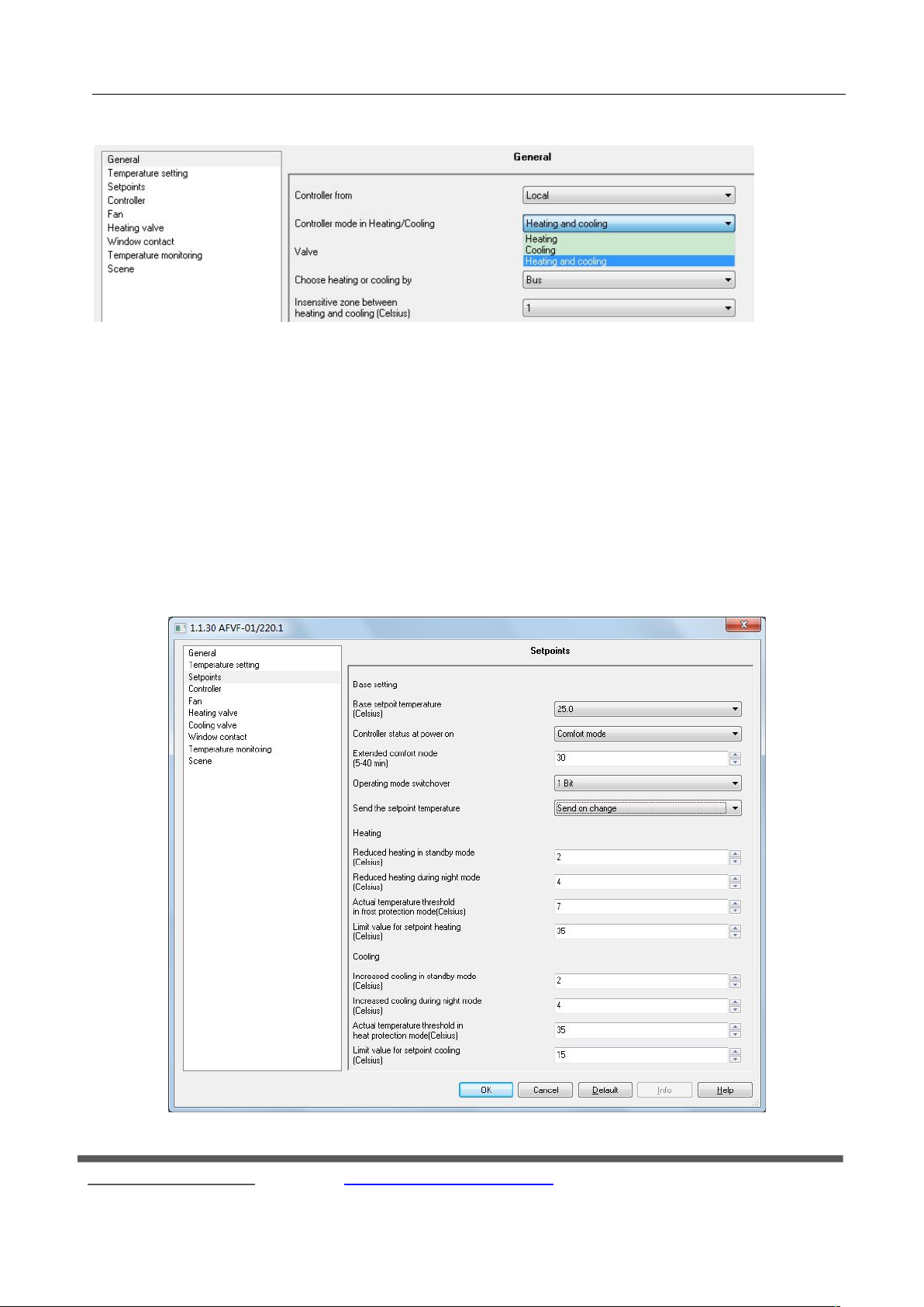
to adjust the room temperature setting , indoor outdoor temperature can not be too large. As below:
○
R
KNX/EIB Fan Coil Controller
18
Fax:(8620)39338465
Page 19
R
Fig. 4.3.2 parameter window “External temperature”
4.4 Parameter window "Setpoints"
GVS K-BUS
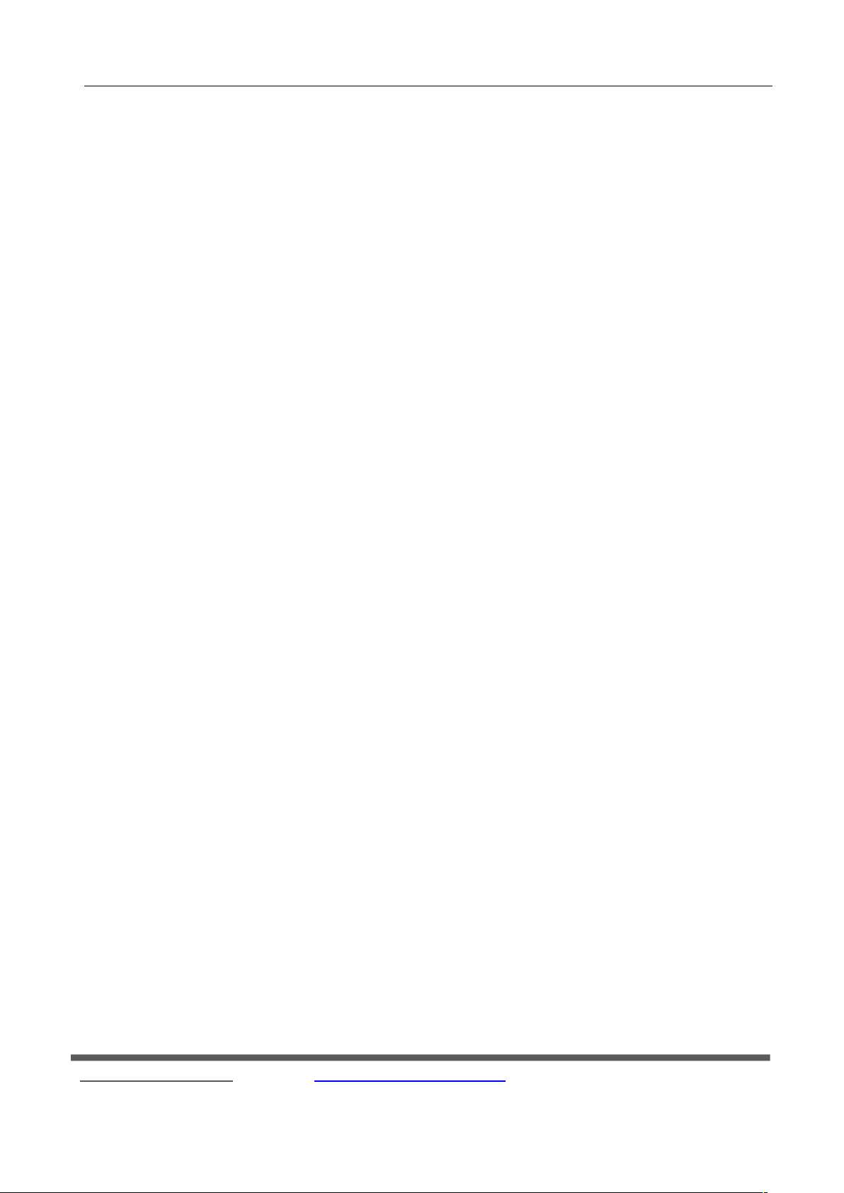
"Setpoints" parameter setting window is shown in Figure 4.4. It is for setting the basic setpoint temperature of
○
KNX/EIB Fan Coil Controller
heating or cooling. Divided into "Base setting", "Heating" and "Cooling" three parts, "Heating" and "Cooling"
parameter can be seen when choosing the appropriate heating or cooling option in parameter "Controller mode in
Heating / Cooling" in the "General" page, Following is detail description for each of the parameter settings.
Fax:(8620)39338465
19
Page 20
R
GVS K-BUS
○
KNX/EIB Fan Coil Controller
Fig. 4.4.1 parameter window “Setpoints”
Base setting
Setting the basic setting for either heating or cooling
Parameter: Base setpoint temperature
Options: [° C] 15 ... 30
This parameter is a reference value to set the set temperature, the set temperature of room modes generated via
the value.
Parameter: Controller status at power on
Options: Standby mode
Comfort mode
Night setback
Frost protection
Setting of the operation mode when connecting the supply voltage.
Parameter: Extended comfort mode
Options:[min.] 0 ... 1-255
The comfort mode parameter is set delay time. When the setting is "0", it means do not use comfort mode
delay function; when set value at 1-255, the room mode Night mode switch back from comfort mode, this function
is enabled, comfort mode will be delayed user settings, when the delay time exceeds the set value, it will
automatically switch to night mode. This mode is only for night mode and comfort mode switch.
Parameter: operating mode switchover
Options: 1bit
1byte
This parameter sets the operating room Switching mode.
Select 1bit, according to the writing of ON or Off, switch to a different mode. Switch to the attention of
priority, if you want to enter the low level mode, you must first close the high level mode, otherwise unable to enter
the low level mode. Mode priority is as follows: Mode of priority is as follows: protected mode (Frost / heat
protection mode)> Comfort mode (comfort mode)> Night mode (night mode)> standby mode (standby mode).
When selected 1byte, 1 comfort mode, said preparation mode 2, 3 for the night mode, 4 denotes a protective
mode, different values are written into the mode is not the same.
Parameter: Send the setpoint temperature
Options: Send on change
Fax:(8620)39338465
20
Page 21
R
GVS K-BUS
Send cyclically
This parameter is set to send mode temperature setpoint.
"Send on change" means that there is a change occurs when the set temperature set temperature.
"Send cyclically" means that periodically sends the temperature setpoint.
Parameter: Period for cyclical sending
Options: [min.] 2 ... 255
This parameter is set to send the set temperature cycle time. In the parameter "Sending the setpoint
temperature" select "Send cyclically" is visible.
Heating / Cooling
The two parts under the "General" parameter page "Controller mode in Heating / Cooling" select the
appropriate "Heating" or "Cooling" or "Heating and Cooling" see the different open. Mainly used to set the room
temperature setting various modes.
○
KNX/EIB Fan Coil Controller
Parameter: Reduced heating in standby mode
Parameter: Increased cooling in standby mode
Options: [° C] 0 ... 10
This parameter is set ready mode, the set temperature. When set to "Heating" mode, the standby mode is set as
the reference value minus the temperature values of options; when set to "Cooling" Mode, the standby mode is
set as a reference temperature value plus the value of the options available.
Parameter: Reduced heating during night setback
Parameter: Increased cooling during night setback
Options: [° C] 0 ... 10
This parameter is set in night mode set temperature. When set to "Heating" mode, night mode setting
temperature of the reference value minus the value of the options; when set to "Cooling" Mode, night mode setting
temperature of the reference value plus the value of the options.
Parameter: Actual temperature threshold in frost protection mode
Options [° C] 2 ... 10
Parameter: Actual temperature threshold in heat protection mode
Options [° C] 5 ... 40
This parameter is set overheating or frost protection mode set temperature. When the indoor heating mode
when the frost protection mode, when the room temperature falls to the options available for the set temperature
21
Fax:(8620)39338465
Page 22
R
4.5 Parameter window "Controller"
GVS K-BUS
value, the controller outputs a control not to fan coil temperature is below the set temperature value; cooling mode
when the room is The over-temperature protection mode when the room temperature rises to a set temperature value
of the option, the controller outputs a control not to fan coil temperature is higher than the set temperature value.
For example: When the room for the heating mode, this parameter is set at a temperature of 10 ° C, room
temperature below 10 ° C, in order to play a protective role, the controller will output control ensure outdoor at 10 °
C or so.
When the room is cooling mode, the parameter setting temperature of 30 ° C, the outside temperature is higher
than 30 C, is also meant to play a protective role, the system will output control ensures outdoor at 30 ° C or so.
Parameter: Limit value for setpoint heating
Options: [° C] 5 ... 40
Parameter: Limit value for setpoint cooling
Options: [° C] 5 ... 60
○
KNX/EIB Fan Coil Controller
This parameter is set heating or cooling set temperature limits. When set to "Heating" mode, the set
temperature is not higher than this value, if the output value is higher than the click; when set to "Cooling" Mode,
the set temperature not lower than this value, if the output value is less than the click.
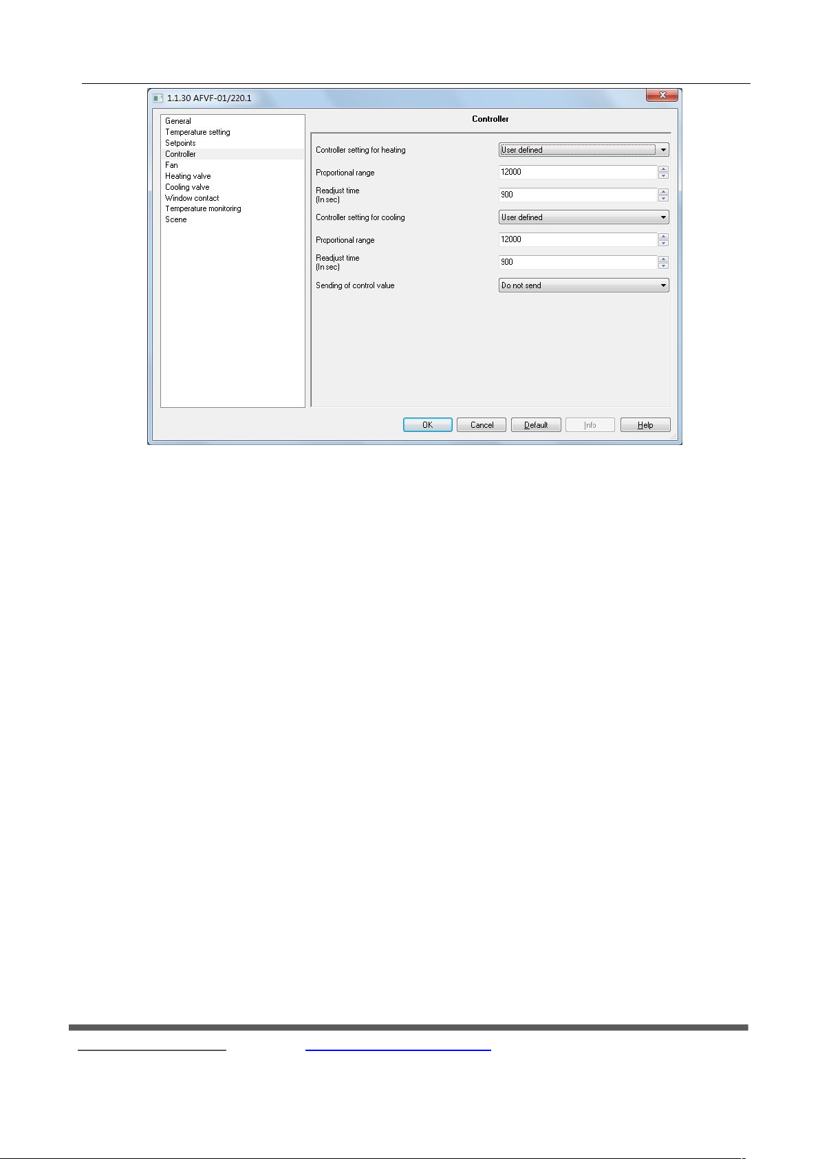
Controller" parameter setting window is shown in Figure 4.5. The interface is mainly set up in the case of
"
heating or cooling the parameters of the PI controller. The following detailed description of each parameter settings.
Fax:(8620)39338465
22
Page 23
GVS K-BUS
○
R
KNX/EIB Fan Coil Controller
Fig. 4.5 parameter window "Controller"
Parameter: Controller setting for heating
Parameter: Controller setting for cooling
Options: - Slow
- Normal
- Fast
- User defined
This parameter is set when setting the heating or cooling of PI corresponding
Slow: the I-gain 1800 s
Normal: the I-gain 900 s
Fast: the I-gain 450 s
Parameter: Proportional range
Options: 0 ... 65,535
Parameter: Readjust time
Options: 0 ... 65,535 (900)
Setting parameters of the PI controller. In the parameter "Controller setting for heating" or "Controller setting
for cooling" option is "User defined" visible.
Parameter: Sending of control value
Fax:(8620)39338465
23
Page 24
R
4.6 Parameter window "Fan"
GVS K-BUS
Options: - Do not send
-Send on change
-Send cyclically
The transmission control parameters by value.
"Do not send" is not sent to the bus control value;
"Send on change" for the control value is changed certain value, the controller was sent on to the bus control
value;
"Send cyclically" Send for the cycle, that every once in a while sends a control value.
Parameter: Period for cyclical sending of control value
Options: [min.] 2 ... 255
The parameter values for the cycle time of transmission control. That is periodically sent once control
values. Parameter "Send of control value" option to "Send cyclically" is visible.
○
KNX/EIB Fan Coil Controller
Parameter: Differential value for sending the control value
Options: [%] 1 ... 10
The parameter values for the control of the percentage change in the option, the fan coil controller sends a
control value to the bus. In the parameter entry "Send of control value" option for the "Send on change" is visible.
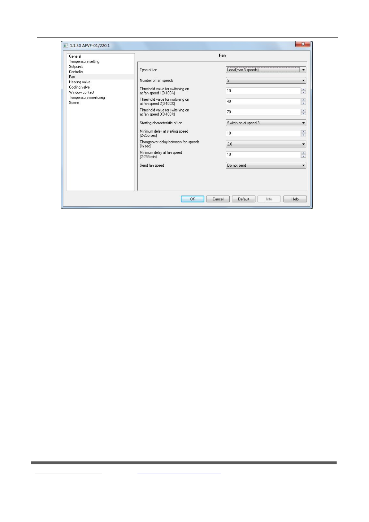
"Fan" parameter setting window is shown in Fig. 4.6.1. The interface is mainly to set the fan speed of some
parameters. The following detailed description of each parameter settings.
Fax:(8620)39338465
24
Page 25
GVS K-BUS
○
R
KNX/EIB Fan Coil Controller
Fig. 4.6.1 parameter window "Fan"
Parameter: Type of fan
Options: - No fan
- Local (max. 3 speeds)
- KNX: on / off
-KNX: 3 speeds
-KNX: 0 ... 100%
This parameter sets the type of the fan.
"No fan" with no fan control, and no parameter is optional;
"Local (max. 3 speeds)" for the controller controls the local relay output to achieve control fan speed
adjustment;
Options "KNX: on / off", "KNX: 3 speeds", "KNX: 0 ... 100% "as the controller viaKNX to control the packets
on the bus other types of wind turbine output.
When the option is "No fan", "KNX: on / off", "KNX: 3 speeds" and "KNX: 0 ... 100%", the controller of the
fan three way switch through the object 31, the object 32 and the object 33 to control the output.
Parameter: Number of fan speeds
Options: - 1
Fax:(8620)39338465
25
Page 26
R
GVS K-BUS
- 2
- 3
This parameter is the number of stalls set up wind speed. According to the actual needs of fan coil, the user can
select the fan speed is divided into several files. This parameter is only in the parameter "Type of fan" option for the
"Local (max.3speeds)", "KNX 3speeds" and "KNX 0 ... 100%" is visible.
Parameter: Threshold value for switching on at fan speed 1
Parameter: Threshold value for switching on at fan speed 2
Parameter: Threshold value for switching on at fan speed 3
Options: [%] 0 ... 100
The parameter for the fan gears threshold setting. The output is the output gear of the actual control value
representing the maximum control value (10000) to achieve a percentage.
"Threshold value for switching on at fan speed 1" means that the threshold value of output gear 1;
○
KNX/EIB Fan Coil Controller
"Threshold value for switching on at fan speed 2" means that the threshold value of output gear 2;
"Threshold value for switching on at fan speed 3" means that the threshold value of output gear 3.
Threshold value 1 < threshold value 2 < threshold value 3. This parameter is only in the
parameter "Type of fan" option for the "Local (max.3speeds)", "KNX 3speeds" and "KNX 0 ... 100%" is visible.
Parameter: Starting characteristic of fan
Options: - switch on at speed 1
- Switch on at speed 2
- Switch on at speed 3
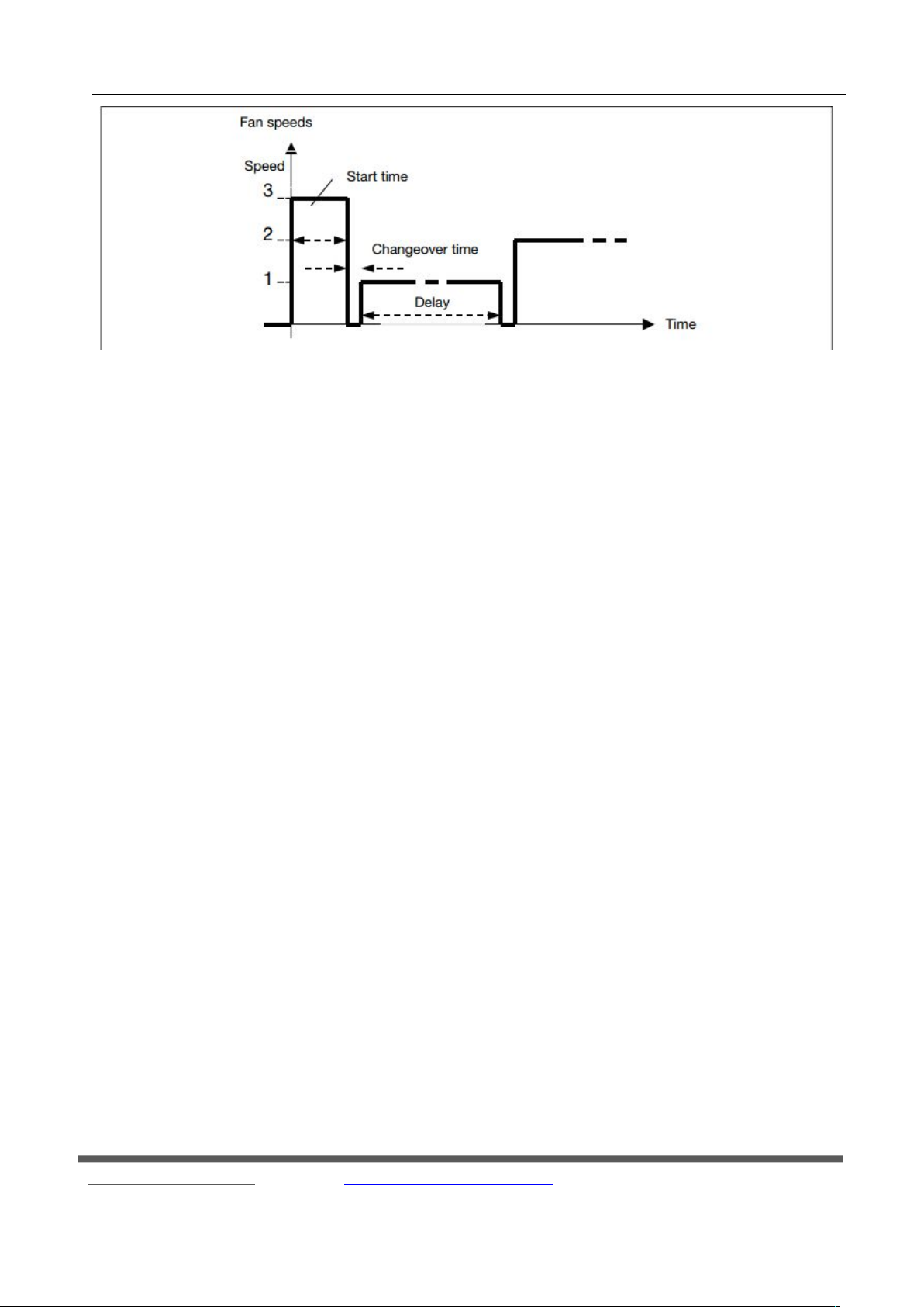
This parameter is set to start the fan speed, in order to stably start the fan motor, preferably starting from the
high speed, so that a high torque can be obtained. When the start time has elapsed, the wind speed is controlled by
the controller on the output value. Fans action following figure 4.6.2 below. This parameter is only in the
parameter "Type of fan" option for the "Local (max.3speeds)", "KNX 3speeds" and "KNX 0 ... 100%" is visible.
Fax:(8620)39338465
26
Page 27
R
GVS K-BUS
○
KNX/EIB Fan Coil Controller
Fig. 4.6.2 fan gear shifting mode
Parameter: Minimum delay at starting speed
Options: [sec.] 2 ... 255
The parameter sets the minimum delay at the starting speed.
Parameter: Changeover delay between fan speeds
Options: [sec.] 0.5 ... 10
This parameter sets the changeover delay between the fan speeds
Parameter: Minimum delay at fan speed
Options: [min.] 2 ... 255
This parameter sets the minimum delay at a fan speed. This parameter should be selected so that a fault is
avoided by changing over the fan speed too frequently.
Parameter: Send fan speed status
Options: -Do not send
-Send on change
-Send cyclically
The parameter sets the sending function of the fan speed status. It is only visible in the parameter
"Type of fan" option for the "Local (max.3speeds)".
"Do not send" is not sent on to the bus speed of the status report;
"Send on change" as the wind changes state reports status to the bus;
"Send cyclically" is sent once every so often cycle speed state, when there is wind condition Change is also
sent, this time sending time re-timing cycle.
Fax:(8620)39338465
27
Page 28
GVS K-BUS
4.7 Parameter window “heating valve” and “cooling valve’
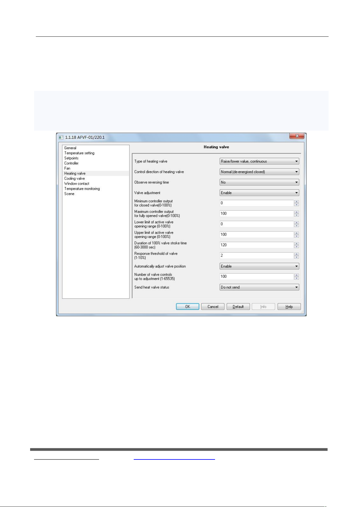
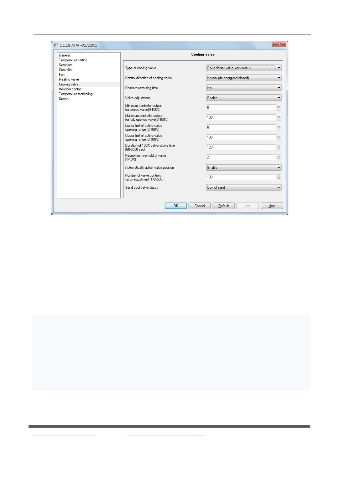
“Heating valve” and “cooling valve” parameter setting windows are shown in fig. 4.7.1 and fig. 4.7.2. They are
respectively used to set some parameters of the heating and refrigeration valves. The following detailed settings for
each parameter.
○
R
KNX/EIB Fan Coil Controller
Fig. 4.7.1 parameter window “Heating valve”
Fax:(8620)39338465
28
Page 29
GVS K-BUS
Parameter : Type of heating valve
Parameter: Type of cooling valve
Option Parameter:--Raise/lower valve, continuous
– Raise/lower valve, pulse width modulation
– Thermal valve
– BUS valve, continuous
– BUS valve, pulse width modulation
This parameter is to set the controller controls the type of valve. It can control the local valve also can
control valves on the KNX bus. Valve has two types, one for the switch type, and the other is a continuous type.
Raise/lower valve, continuous” Represents the local movements of continuous control valve;
“Raise/lower valve, pulse width modulation”represent the rise and fall of local PWM control valve.
BUS valve, continuous”represnet bus continuous valve;
BUS valve, pulse width modulation”express the switching valve on the bus.
Parameter:Control direction of heating valve
Parameter:Control direction of cooling valve
○
R
KNX/EIB Fan Coil Controller
Fig. 4.7.2 parameter window “Cooling valve”
Fax:(8620)39338465
29
Page 30
GVS K-BUS
Optional: – Normal (de-energised closed)
–Inverted (de-energised open)
This parameter is to set the direction of the valve switch.
Continuous valve "Normal (de-energised closed)" is positive; "Inverted (de-energised open)" to reverse.
Switch valves "Normal (de-energised closed)" indicates a normally closed switch; "Inverted (de-energised
open)" indicates normally open switch.
Parameter:Observe reversing time
Option: -No…500ms…1.5s
This parameter is set to toggle continuous valve switch delay time. When the valve type is continuously
adjustable, in order to prevent frequent switching valve switch, opening or closing the valve needs to be suspended
for some time. This parameter is only in the parameter entry "Type of heating valve" or "Type of cooling valve"
select "Raise / lower valve, continuous" or "Raise / lower valve, pulse width modulation" is visible.
Parameter:Valve adjustment
Option: – Enable
– Disable
The parameter can be adjusted to make the characteristic curve of the valve
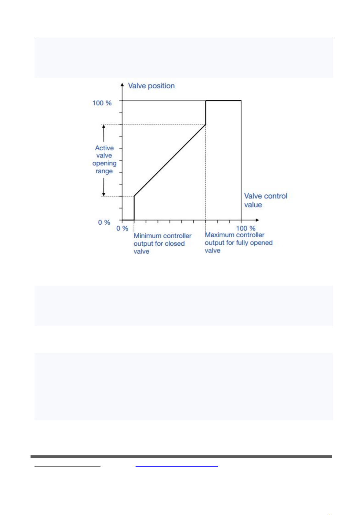
Parameter:Minimum controller output for closed valve
Parameter:Maximum controller output for fully opened valve
Parameter:Lower limit for active valve opening range
Parameter:Upper limit for active valve opening range
Option: [%] 0...100
This parameter is for setting the valve output characteristic curve.
“Minimum controller output for closed valve”show the scope of the control values of lower limit value
“Maximum controller output for fully opened valve”show the the scope of the controlled variable upper limit;
“Lower limit for active valve opening range” This value represents the lower limit value of the valve is
limited;
“Upper limit for active valve opening range” This value represents the upper limit value of the valve is limited.
For different valves, the limited is different:“Raise/lower valve, continuous” travel time is limited;
“ Raise/lower valve, pulse width modulation”、“Thermal valve” and“BUS valve, pulse width modulation”PWM
○
R
KNX/EIB Fan Coil Controller
Fax:(8620)39338465
30
Page 31
GVS K-BUS
cycle is limited; “BUS valve, continuous” Restricted is made out of a heating or cooling control values. This
parameter is only in the parameter entry "Valve adjustment" select “Enable” is visible.
To Raise/lower valve, continuous valve as an example, the output value of the diagram
Parameter:Duration of 100 % valve stroke time
Option: [sec.] 60...3,000
This parameter is set continuous valve travel time. Travel time refers to the valve from the closed to open to
the maximum time value, this parameter only in the parameter entry "Type of heating valve" or "Type of cooling
valve" select "Raise / lower valve, continuous" or "Raise / lower valve, pulse width modulation "when visible.
Parameter: Response threshold of valve
Options: [%] 1 ... 10
The parameter values for the setting controls the amount of change. When the control value percentage
change of the parameter, the controller will output once the valve control. Therefore, the larger value of this
parameter to adjust the switching frequency of the smaller valve, on the contrary, the smaller the value, adjust the
valve's switching frequency is greater. This parameter is only in the parameter entry "Type of heating valve" or
"Type of cooling valve" select "Raise / lower valve, continuous" or "BUS valve, continuous" when visible
Parameter:Automatically adjust valve position
○
R
KNX/EIB Fan Coil Controller
Fax:(8620)39338465
31
Page 32
GVS K-BUS
Option: -Enable
-Disable
The parameter settings are automatically corrected for the continuous valve opening. This parameter is only in
the parameter entry "Type of heating valve" or "Type of cooling valve" select "Raise / lower valve, continuous" or
"Raise / lower valve, pulse width modulation" when visible.
Parameter: Number of valve controls up to adjustment
Option:1...65535
This parameter is set automatically correct valve opening count. In continuous valve opening and closing
process, the valve stop time period of one frequency each, when the count equals the set count value, the valve will
be fully closed, the valve closing time is: travel time 0.5 * (0.5 * journey time: maximum of 1min). This parameter
is only in the parameter entry "Automatically adjust valve position" of the option to "Enable" when open see.
Parameter:Cyclic time for heating valve
Parameter:Cyclic time for cooling valve
Option: for heating valve [min.] 1...255
Option: for cooling valve [min.] 1...255
This parameter is the time period of the PWM control. The larger the value of this parameter, the valve
switching frequency is smaller, on the contrary, the smaller the value, the more frequent valve switch. This
parameter is only in the parameter entry "Type of heating valve" or "Type of cooling valve" select "Raise / lower
valve, pulse width modulation", "Thermal valve" or "BUS valve, pulse width modulation" can be seen.
Parameter: Send heat valve status
Parameter: Send cool valve status
Options:-Do not send
-Send on change
-Send cyclically
This parameter is set to send the local way valve status report. It is only visible in the parameter entry "Type of
heating valve" or "Type of cooling valve" select "Raise / lower valve, pulse width modulation", "Thermal valve" or
"BUS valve, pulse width modulation".
"Do not send" on the bus to not to send local valve status report;
"Send on change" as a local change in a certain amount of valve status report to the bus state;
"Send cyclically" is sent once per cycle intervals local valve status.
○
R
KNX/EIB Fan Coil Controller
Fax:(8620)39338465
32
Page 33
GVS K-BUS
Parameter: Differential value for sending
Parameter: Differential value for sending
Options: [%] 1 ... 10
This parameter sets the local valve status change. When the valve is continuously changing the local value of
the parameter, the controller sends a valve to the bus state values. This parameter is only in the parameter entry
"Send heat valve status" or "Send cool valve status" select "Send on change" when open see.
Parameter: period for cyclical sending
Options: [min.] - 2 ... 255
This parameter is set to send the local valve state the time period. This parameter is only visible in the
parameter entry "Send heat valve status" or "Send cool valve status" select "Send cyclically".
Parameter: Send of 1 byte control value
Options: Send on change
Send cyclically
This parameter is set to control external continuous valve control value is sent. This parameter is only visible
in the parameter entry "Type of heating valve" or "Type of cooling valve" select "Raise / lower valve, continuous",
"Raise / lower valve, pulse width modulation" or "Raise / lower valve, pulse width modulation ".
Parameter: Differential value for sending
Options: [%] 1 ... 10
This parameter is set when the external continuous valve control options in the percentage change in value is
sent when a valve control values. This parameter is only visible in the parameter entry "Send of 1 byte control
value" select "Send on change”.
Parameter: Period for cyclical sending of control value
Options: [min.] - 2 ... 255
This parameter is set to send out an external continuous controller valve control value cycle. This parameter is
only visible in the parameter entry "Send of 1 byte control value" select "Send cyclically".
○
R
KNX/EIB Fan Coil Controller
Fax:(8620)39338465
33
Page 34
GVS K-BUS
4.8 Parameter window "Window contact"
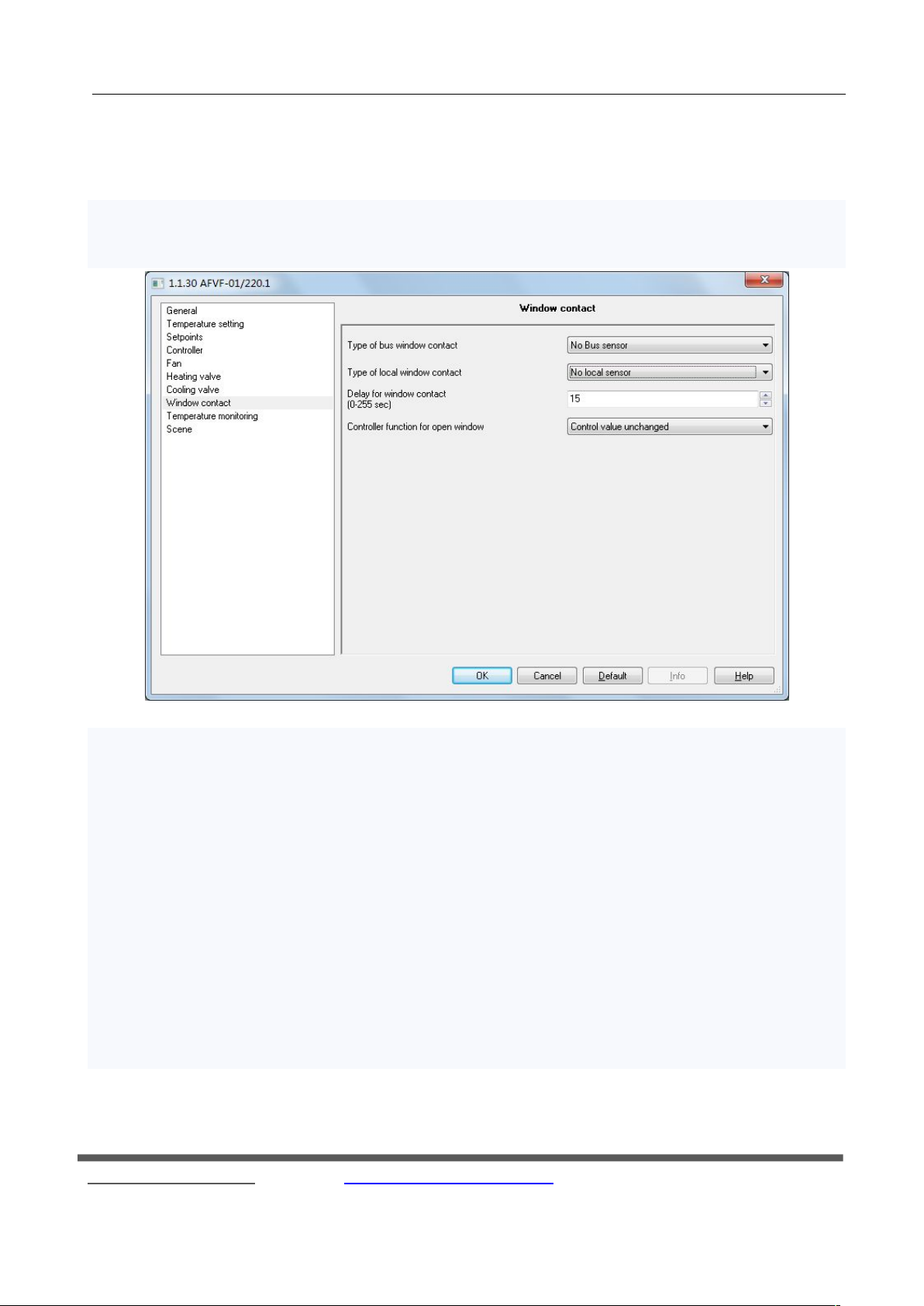
"Window contact" parameter window is shown in Fig. 4.8. The page is mainly used to set the window
switch status parameters. The following detailed description of each parameter settings.
Parameter: Type of bus window contact
Options: No BUS sensor
Normal
Inverted
The parameter settings from the windows on the bus type of contact.
"No Bus sensor" means that no bus window sensor;
"Normal" indicates the input mode to forward the bus window, the object 13 receives the bus up the "0" is that
the windows are opened, "1" is turned off;
"Inverted" indicates that the bus windows input mode is reverse, ie up to the bus object 13 receives "1" is that
the windows are open, "0" is off.
○
R
KNX/EIB Fan Coil Controller
Fig. 4.8 parameter window “window contact”
34
Fax:(8620)39338465
Page 35
GVS K-BUS
When the controller detects the windows open, the controller will output parameter entry "Controller function
for open window" in the parameters set.
Parameter: Type of local window contact
Options: No local sensor
Contact open: window open
Contact closed: window open
Input: normal
Input: inverted
This parameter is set up a local window switch contacts or binary input.
"No local sensor" means no window switch contact sensor ( Binary input is invalid );
"Contact open window open" means that the windows contacts open , the communication object 30 sends
"0" , the contacts close a communication object sends "1";
"Contact closed window open" means that the windows closed contacts, the communication object 30
sends "0" , the contacts open communication object sends "1 ."
"Contact open window open" and "Contact closed window open" In both cases, the controller detects the
windows open, the controller will output parameter entry "Controller function for open window" in the set
parameters;
While "Input: normal" input voltage is detected, the communication object 30 sends "1”, opposite to send
"0";
"Input: inverted" voltage input is detected , the communication object 30 sends "0" , opposite to send "1";
"Input: normal" and "Input: inverted " detects only the binary input status does not affect the fan coil
controller's normal output.
Parameter: Delay for window contact
Options: [s] 0 ... 255
This parameter is the window detection delay time. When the window is opened temporarily , not always
open, can use this parameter to distinguish the time , that is, when the window opening time value set in the
parameter within the window that has not been opened , if the time exceeds the setting value , then that
window has been opened .
Parameter: Controller function for open window
Options: Normal (active)
○
R
KNX/EIB Fan Coil Controller
Fax:(8620)39338465
35
Page 36
GVS K-BUS
Control value = 0 (all off)
Control value unchanged
The parameter setting window is opened for the operation of the controller .
"Normal" fan coil controller output at normal control value;
"Control value = 0 (all off)" fan coil controller output control value is 0, then the fan coil valves and wind
are closed;
"Control value unchanged" for the fan coil controller maintains a constant output current value.
4.9 Parameter window "Temperature monitoring"
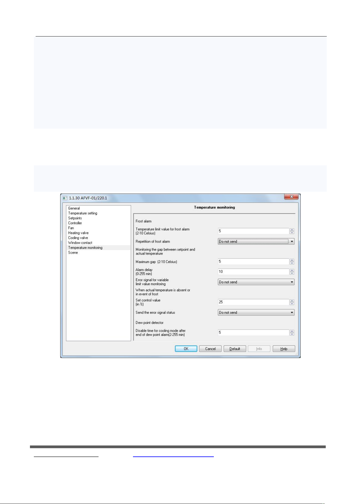
"Temperature monitoring" parameter setting window is shown in Fig. 4.9. It is mainly used to set the
temperature of alarm. Hereunder is the detail information of each parameter.
Frost alarm
Parameter:Temperature limit value for frost alarm
Options: [°C] 2...10
Setting the temperature of frost alarm. When the room temperature is lower than this setting one, the controler
will send the signal of frost alarm to the bus.
○
R
KNX/EIB Fan Coil Controller
Fig. 4.9 parameter window "Temperature monitoring"
Fax:(8620)39338465
36
Page 37
GVS K-BUS
Parameter:Repetition of frost alarm
Options: Do not send
Send on change
Send cyclically
Setting the mode of sending out the frost alarm.
“Do not send” means don’t send the frost alarm to the bus;
“Send on chang” means sending the signal to the bus when the forst alarm is changed;
“Send cyclically” means sending the signal periodically, and also the time when the frost alarm is changed,
after that, the cycle time is recounted.
Parameter:Period for cyclical sending of frost alarm
Options: [min.] 2...255
Setting the cycle of sending the signal of frost alarm. This parameter is available only when you select “Send
cyclically” in parameter “Repetition of frost alarm”.
Parameter:Maximum gap
Options: [°C] 2...10
Setting the alarm value between actual temperature and setting temperature. When the gap between the actual
temperature and setting temperature is lager than the setting value, controler will send signal of alarm to the bus.
Parameter:Alarm delay
Options: [min.] 0...255
Setting the delay time of sending out the gap alarm. When the gap between actual temperature and setting
temperature is lager than the setting parameter “Maximum gap”, the controler will not send the alram to the bus
immediately, instead it will detect if the gap keeps larger than the value during the delay time, if yes, the controler
will send the alarm to the bus after the delay time, if not, it won’t send the alarm.
Parameter:Error signal for variable limit value monitoring
Options: Do not send
Send on change
Send cyclicall
Setting the mode of sending out the gap alarm. When the gap between actual temperature and setting
temperature is lager than the setting value, set the mode of sending out the gap alarm.
○
R
KNX/EIB Fan Coil Controller
37
Fax:(8620)39338465
Page 38
GVS K-BUS
“Do not send” means don’t send the alarm to the bus;
“Send on chang” means sending the signal to the bus when the alarm is changed;
“Send cyclically” means sending the signal periodically, and also the time when the alarm is changed, after that,
the cycle time is recounted.
Parameter:Period of sending error signal
Options: [min.] 1...255
Setting the cycle of sending the signal of gap alarm. This parameter is available only when you select “Send
cyclically” in parameter “Error signal for variable limit value monitoring”.
when actual temperature is absent or in event of frost
Parameter:Set control value
Options: [%] 0...100
Setting the output value of the controler when the setting temperature is error. When the actual temperature is
absent or in event of frost, controler will send out the value according to the percentage of the setting parameter.
Parameter:Send the error signal status
Options: Do not send
Send on change
Send cyclically
Setting the mode of sending out the error sets. Error sets including: indoor temperature alarm, outdoor
temperature alarm, frost alarm, gap alarm, dew point alarm, KNX window opened alarm, and local window opened
alarm. You could send by 1 bit or 1 byte.
“Do not send” means don’t send the error sets to the bus;
“Send on chang” means sending the signal to the bus when the error stes are changed;
“Send cyclically” means sending the signal periodically, and also the time when the error stes are changed,
after that, the cycle time is recounted.
Parameter:Group Errors report type
Options: 1 Bit
1Byte
Setting the type of sending out the error sets.
○
R
KNX/EIB Fan Coil Controller
38
Fax:(8620)39338465
Page 39
GVS K-BUS
“1 Bit” means when whatever one alarm of the error sets is happened, controller will send the signal of alarm
in 1 bit.
“1 Byte” means each alarm of the error sets, each number represents:
Bit no: 0 : actual temperature alarm
1: external temperature alarm
2: frost alarm
3: gap alarm
4-7:no use
This parameter is available only when you select “Send on change “or “Send cyclically” in parameter “Send
the error signal status”.
Parameter:Period of sending error information
Options: [min.] 1...255
Setting the cycle of sending the signal of error sets. This parameter is available only when you select “Send
cyclically” in parameter “Send the error signal status”.
Dew point detector
Parameter:Disable time for cooling mode after end of dew point alarm
Options: [min.] 1...255
Setting the disable time for cooling mode after end of dew point alarm. When fancoil controller receives dew
point alarm from bus, it will shut down the valve and fan, and recover when the alaram is clear and the disable time
is over.
4.10 Parameter window “Scene”
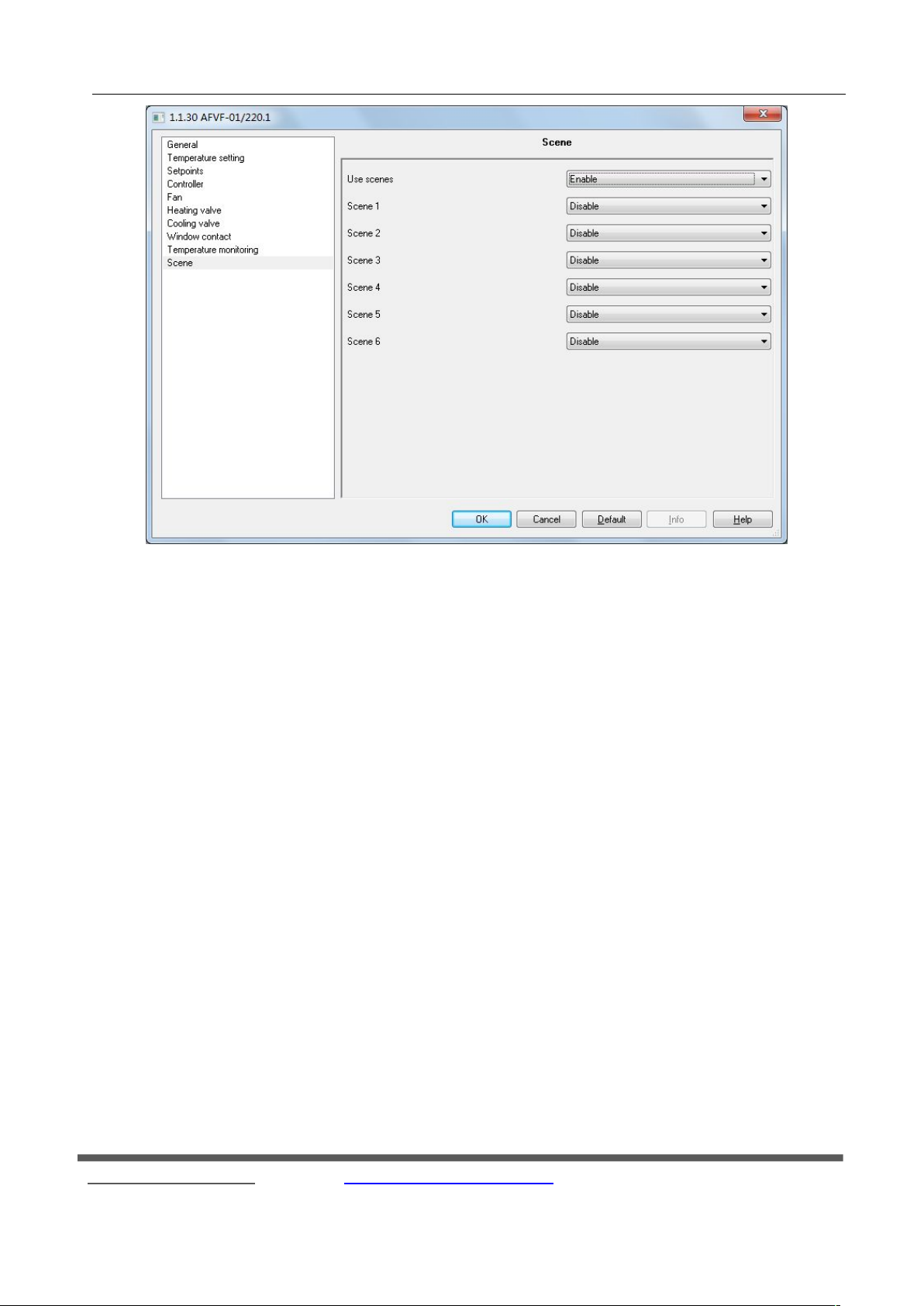
Fig. 4.10 is the parameter setting window of “Scene”. It is used to set the scene parameter, such as the mode
of room, heating or cooling, wind speed, etc. When you use scene, the controller will default it is manual control
mode. Hereunder is the detail of each parameter.
○
R
KNX/EIB Fan Coil Controller
39
Fax:(8620)39338465
Page 40
GVS K-BUS
Fig. 4.10 parameter s window “Scene”
Parameter:Use scenes
Options:Enable
Disable
Setting the scene. There are 6 scenes can be choosed.
Parameter:Scene 1-6
Options:Enable
Disable
There are 6 scenes can be choosed, but each time, you can select only 1 scene.
Parameter:Scene number
Options:1…64
Setting the scene numbers. No.1-64 corresponding to telegram 0-63
Parameter:Mode
Options: Standby mode
Comfort mode
Night setback
○
R
KNX/EIB Fan Coil Controller
Fax:(8620)39338465
40
Page 41
GVS K-BUS
Frost protection
Parameter:Fan
Options: No change
High
Medium
Low
Off
Setting the wind speed of each scene.
“No change” means keep the same speed.
“High”, “Medium”, “Low” means the different wind speed.
“Off” means to shut down the fan.
Parameter:Heating or Cooling
Options: No change
Auto
Heating
Cooling
This parameter is to set the controller for heating or cooling.
"No change" means that at the current value of the output of heating or cooling;
"Auto" means that the heating or cooling by the controller;
"Heating" means to set the controller for the heating mode;
"Cooling" means to set the controller for the cooling mode.
This parameter is only can be seen when be selected with the “Heating and cooling"in the "Controller mode in
Heating / Cooling" function.
4.11 External control parameter setting interface
External control parameter setting interface is mainly used to set the external controller to the local control
valve and fan parameters representing the device into the controlled mode. The following detailed description in
this case the description of the parameter settings for each page.
○
R
KNX/EIB Fan Coil Controller
Fax:(8620)39338465
41
Page 42
GVS K-BUS
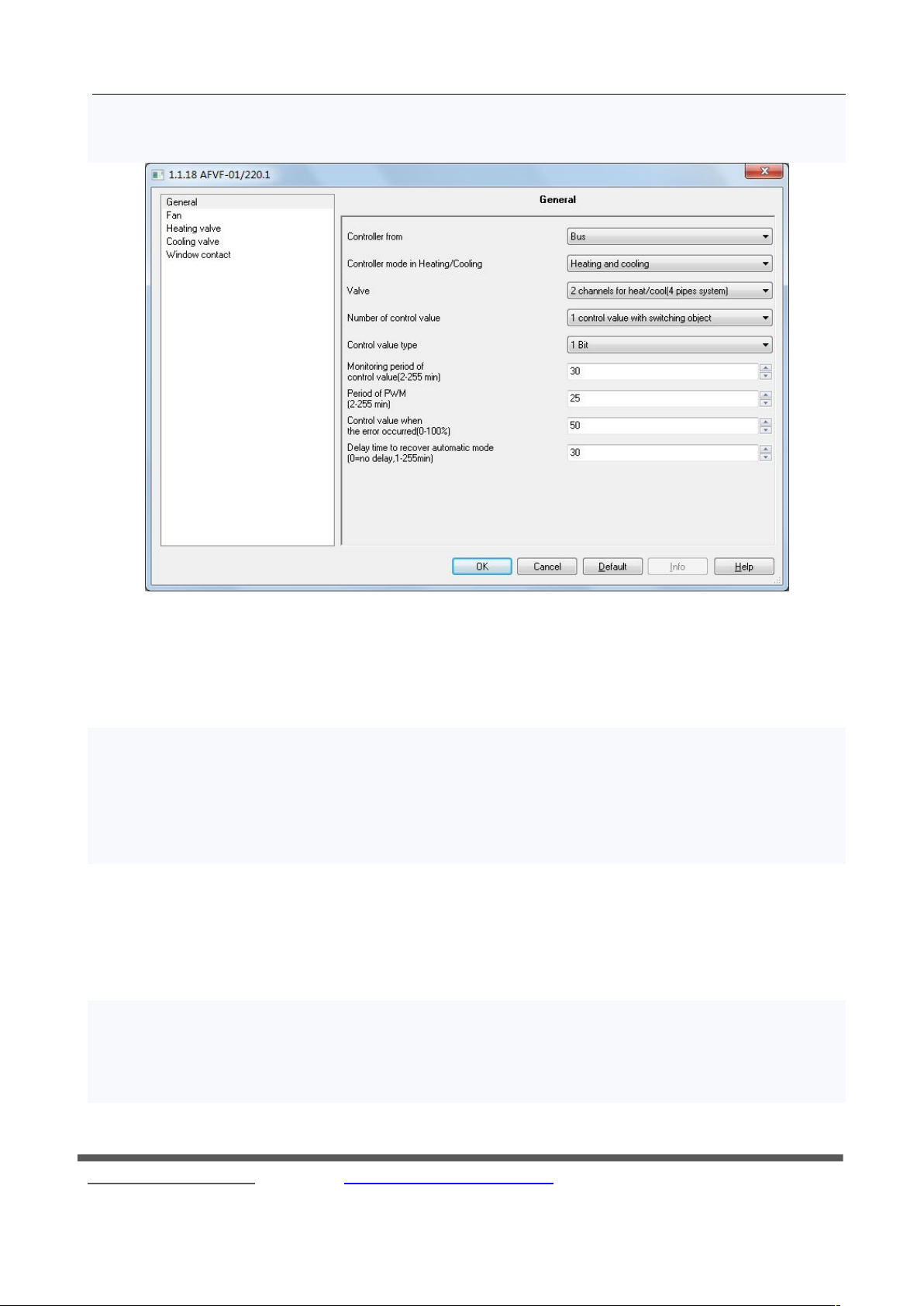
External Control "General" parameter setting interface as shown in Figure 4.11.1, following detailed
description of each of the parameter settings.
Fig. 4.11.1 External Control "General" parameter setting interface
Parameter: Controller from
Options: Local
Bus
This parameter is to set the fan coil controller.
"Local" means that the controller output from the fan coil control.
"Bus" indicates fan coil by an external controller input control, mainly through communication objects of the
fan and valve control.
Parameter: Controller mode in Heating / Cooling
Options: Heating
Cooling
Heating and cooling
This parameter is the setting mode of the controller, can be individually heating or cooling, heating and cooling
can also exist. Fan coil controller automatically according to the actual temperature output corresponding control
values.
○
R
KNX/EIB Fan Coil Controller
Fax:(8620)39338465
42
Page 43
GVS K-BUS
Parameter: Valves
Options: 1 channels for heat / cool (2 pipes system)
2 Channels for heat / cool (4 pipes system)
This parameter is set up out of the water pipe fan coil type.
"1 channels for heat / cool (2 pipes system)" for the heating and cooling shared an inlet and outlet pipe, the hot
and cold water are in and out from the pipes. It only need a valve connected with output of the fan coil heating
valve controller;
"2 channels for heat / cool (4 pipes system)" for the heating and cooling, respectively, have their own access to
water, you need two separate control valves hot and cold water in and out.
Parameter: Number of control value
Options: 1 control value with switching object
2 Control values
This parameter is used to set the external input control valve of communication object number, it is only
visible in the "Parameter: Controller mode in Heating / Cooling" with option "Heating and cooling".
"1 control value with switching object" indicates that only a communication object on the heating valve and
cooling valve control (target 21), switching of heating and cooling through a communication object (object 7) to
achieve;
"2 control values" means a two communication objects to separately control the heating valve and cooling
valve.
Parameter: Control value type
Options: 1 Bit
1 Byte
The parameter values for the selected data type of external control. Local heating and cooling valve
switch based on this control value for output control.
"1Bit" represents an external input control value is 1bit;
"1Byte" represents an external input control value id 1 Byte.
Parameter: Monitoring period of control value
Options: [min.] 2 ... 255
○
R
KNX/EIB Fan Coil Controller
Fax:(8620)39338465
43
Page 44
GVS K-BUS
The parameter values for the monitoring of external control time period, if the control value has not been
updated, but longer than the time set this option; it is considered an external controller error, the controller based on
the output of user-set parameters.
Parameter: Control value when the error occurred
Options: 0 ... 100%
This parameter is when setting the external controller error of control value output percentage. External
controller error, if the parameter entry "Control value type" option to "1 Bit", then the PWM output heating or
cooling of the time as a parameter entry "Period of PWM" multiplied by the time set in this parameter entry
percentage; if the parameter entry "Control value type" option to "1 Byte", then the continuous control of the
percentage of the value set by the user output.
Parameter: Period of PWM
Options: [min.] 2 ... 255
This parameter is the external controller error of the PWM cycle. When the control value of the external
controller is "1Bit" and the control value error is detected, the controller output will follow the PWM cycle. This
parameter is only can be seen when in the parameter "Control value type" when select "1 Bit" value.
Parameter: Delay time to recover automatic mode
Options: [min.] 0 ... 255
This parameter is set to switch back from other modes automatic mode delay time.
Option is "0", the controller does not automatically switch back to automatic mode until the user through the
KNX communication objects or local button to switch back to automatic mode;
For "1-255" when the manual mode or test mode will delay after the switch back to automatic mode.
Fan, Heating valve, Cooling valve and Window contact can refer to the case when the control is internal.
○
R
KNX/EIB Fan Coil Controller
Fax:(8620)39338465
44
Page 45
GVS K-BUS
5. Description of the communication objects
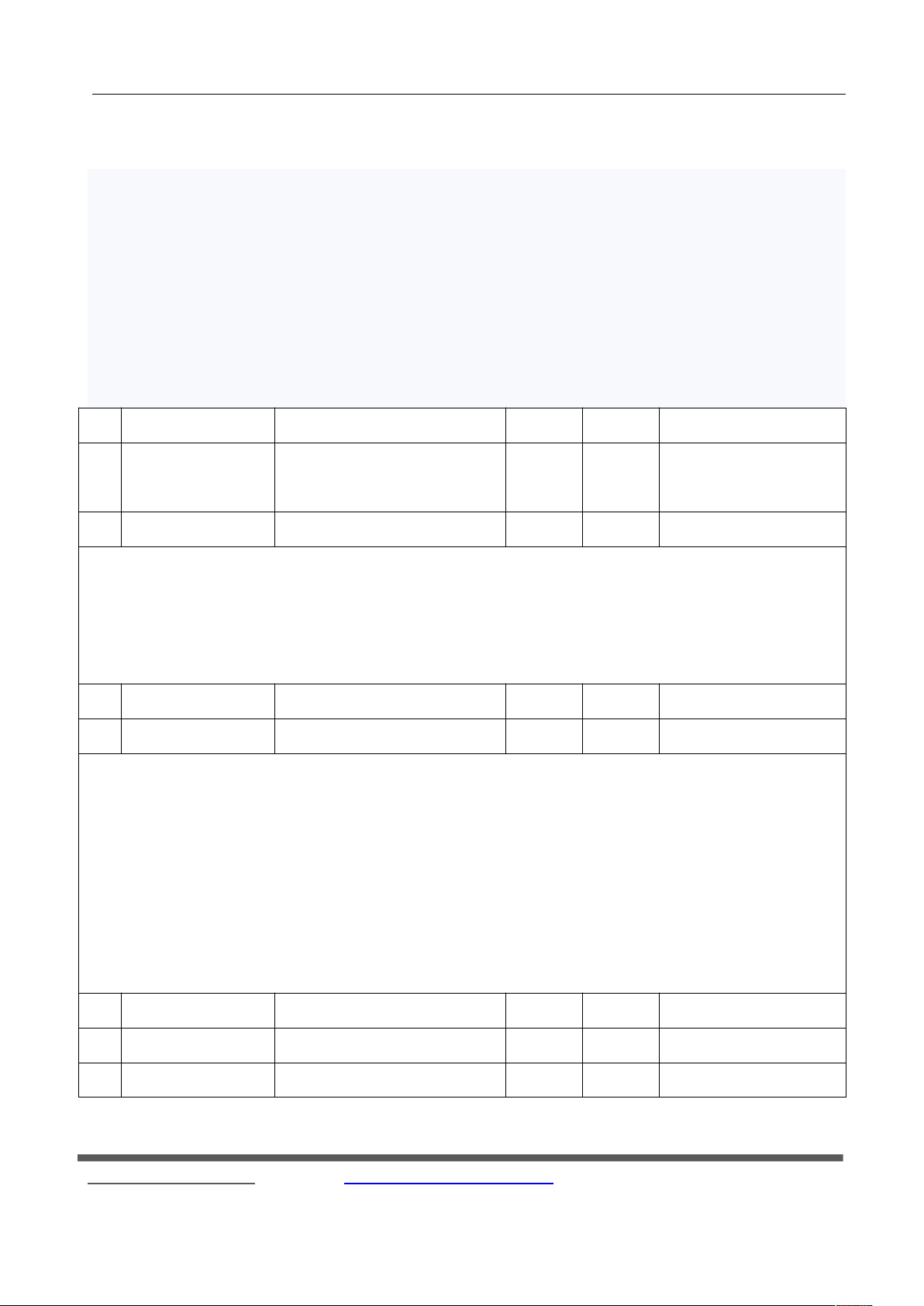
Communication objects are devices on the bus to communicate with other media devices , That is only the
communication objects can communicate on the bus. The following details description of the function of each
communication object.
Note: “C” in “Flag” column in the below table means that the object has a normal link to the bus; “W”
means the object value can be modified via the bus; “R” means the value of the object can be read via the bus; “T”
means that a telegram is transmitted when the object value has been modified; “U” means that value response
telegrams are interpreted as a write command, the value of the object is updated.
No.
Function
Communication Object name
Data Type
Property
DPT
0
Actual temperature
Output, actual temperature
Input, actual temperature
2byte
C,R,T
C,R,W,U
[9.1] DPT_Value_Temp
[9.1] DPT_Value_Temp
1
Actual temperature
Output, actual temperature error
1bit
C,R,T
[9.1] DPT_Value_Temp
Objects 0: Interior actual temperature can be read from the local PT1000 sensors interface t, you can also get
from the bus.
Object 1: indoor temperature error flag, monitoring cycle by setting the indoor temperature to be monitored.
If the actual temperature error occurs, then the object will be sent to the bus signal "1" to alarm.
2
External temperature
Input, external temperature
2byte
C,R,W,U
[9.1] DPT_Value_Temp
3
External temperature
Output, external temperature error
1bit
C,R,T
[1.5] DPT_Alarm
Object 2: the outdoor temperature, the refrigeration case mainly for adjusting the set room temperature, i.e.
when the external temperature is greater than the set point temperature value of "Minimum external temperature
for correcting the set point", the outdoor temperature change of 3 degrees, the temperature setting value change of
1 degree.
Object 3: outdoor temperature error flag, if the "Monitoring period for external temperature" parameter is
received within a set time interval to the external temperature value is not updated, then the object is sent on the
bus signal "1" to Alarm.
4
Setpoint
Input, base setpoint
2byte
C,R,W,U
[9.1] DPT_Value_Temp
5
Setpoint
Input, setpoint adjustment
2byte
C,W,U
[9.1] DPT_Value_Temp
6
Setpoint
Output, instantaneous setpoint
2byte
C,R,T
[9.1] DPT_Value_Temp
○
R
KNX/EIB Fan Coil Controller
Fax:(8620)39338465
45
Page 46
GVS K-BUS
Object 4: The benchmark set temperature. As the setting value for the reference value of the actual output.
The value of the existing heating but also cooling the case with dead zone temperature is used to determine the
current status of the refrigeration or heating.
Object 5: Basis set temperature correction. By writing to the object value, you can set the temperature to be
modified.
Object 6: the actual output set temperature value. The value is sent on the bus to the current set temperature.
7
2-pipe operation
Heating/cooling
Output, heating
Input, heating
Input, heating/cooling
1bit
C,R,T
C,R,W,U
C,R,W,U
[1.1] DPT_Switch
8
2-pipe operation
Output, cooling
Input, cooling
1bit
C,R,T
C,R,W,U
[1.1] DPT_Switch
Object 7: heating enabled.
Object 8: cooling enabled.
In this device as a master device, the two objects as two pipe fan coil open see, you can choose to receive or
send parameters to enable the heating or cooling of the object.
In a controlled device, the object 7 is also used to denote a separate heating or cooling, "0", indicates cooling,
"1" indicates heating.
9
HVAC mode
Input, comfort mode
Input, RTC mode
1bit
1byte
C,W,U
C,W,U
[1.1] DPT_Switch
[20.102] DPT_HVACMode
10
HVAC mode
Input, night mode
1bit
C,W,U
[1.1] DPT_Switch
11
HVAC mode
Input, Frost/heat protection mode
1bit
C,W,U
[1.1] DPT_Switch
Room Mode can be divided into three 1bit objects, (objects 9,10, 11) and one 1byte objects (object 9) to
switch.
1bit object:
Object 9: Room Comfort mode.
Object 10: Room night mode.
Object 11: Room protected mode.
Among them, the corresponding object to write "1" indicates that the corresponding room mode enabled;
write "0" to cancel the corresponding room mode. Note: 3 1bit object has priority: protected mode (Frost / heat
protection mode)> Comfort mode (Comfort mode)> Night mode (Night mode)> Ready Mode (Standby mode),
○
R
KNX/EIB Fan Coil Controller
Fax:(8620)39338465
46
Page 47
GVS K-BUS
when the object 9, the object 10 and object 11 received are zero, then the room is ready mode control mode.
1byte: Enter the number and pattern relationship is as follows:
Bit no: 0: Automatic
1: Comfort mode
2: Ready Mode
3: Room Mode
4: Protected Mode
5-255: Idle invalid
12
Scene
Input, Scene number
1byte
C,W,U
[17.001] DPT_SceneNumber
The object is a scene number. There are six scenes, according to the number of different scenes to recall
different scenes. .
Through this communication object sends an 8bit command can be invoked or stored scenes. This
communication object is enabled as long as the function is enabled for a scene. The following detailed description
of the meaning of 8bit instruction.
Let a 8bit instruction (binary coded): XXNNNNNN
X: 0;
NNNNNN: scene number (0 ... 63).
Parameter setting options are 1 to 64, in fact, the corresponding object value is 0 to 63. If the parameters are
set in Scene 1, the communication object receives the scene should be 0.
13
Window contact
Input, window contact
1bit
C,W,U
[1.1] DPT_Switch
This object is detected on the bus window switch. When the parameter Type of BU window contact options
are "Normal" when the object is to write "1" indicates the windows shut, "0" indicates the windows open; option
"Inverted", to the object write "0" indicates that windows are closed, "1" indicates the windows open. If it detects
an open window on the bus, the controller will follow the parameters Window contact in the "Controller function
for open window" to set the output control values.
○
R
KNX/EIB Fan Coil Controller
Fax:(8620)39338465
47
Page 48
GVS K-BUS
14
Presence sensor
Input, presence detector
1bit
C,W,U
[1.1] DPT_Switch
Presence detection, and presence sensor is connected. Object receives a "1" indicates that someone in the
room; when receives "0" means no one in the room. When someone is detected, regardless of the current room
modes and why modes are forced to switch back to the Comfort mode; when the person is not detected, the room
mode switch back to the previous state of the room modes.
15
Fan
Input, manual operation of fan
1byte
C,W,U
[5.1] DPT_Scaling
Manually adjust the fan speed according to the parameters Fan set percentage of each file to adjust the fan
speed. For example, when "Threshold value for switching on of fan speed 1" in the value of 10, the object 15 to be
greater than 255 * 10% wind a trigger. Object 15 written value, the controller into manual operation mode.
16
Fan
Input, toggling to automatic mode
1bit
C,W,U
[1.1] DPT_Switch
This object is used to switch the controller back to automatic control mode. If the current controller's control
mode for testing or manual mode, the object through to write "1" to switch back to automatic control mode control
mode.
17
Fan
Output, fancoil automatic or not
1bit
C,R,T
[1.1] DPT_Switch
Fan control mode status, 1for the automatic control mode, 0 to manual / test mode.
18
Fan
Output, fan speed status
Output, On/Off
Output, speed 1
1byte
1bit
1bit
C,R,T
C, T
C, T
[5.1] DPT_Scaling
[1.1] DPT_Switch
[1.1] DPT_Switch
19
Fan
Output, speed 2
Output, speed:0-100%
Input, automatic operation of fan
1bit
1byte
1byte
C,T
C,T
C,W,U
[1.1] DPT_Switch
[5.1] DPT_Scaling
[5.1] DPT_Scaling
20
Fan
Output, speed 3
1bit
C,T
[1.1] DPT_Switch
For the controlled device:
Automatic control object 19 (Input, automatic operation of fan) is used to enter the fan control values. Object
18 and object 20 are not used.
As the master device:
When the parameter Fan in "Type of fan" of Local (max.3 speeds), with the object 18 (Output, fan speed
status) to represent the fan speed state of the local valve. 0 (0%) said that fan off, 85 (33.3%) said that the first gear,
170 (66.7%) said that the second gear, 255 (100%) represents the third gear.
When the parameter Fan in "Type of fan" of KNX: on / off, the object 18 (Output, On/Off) is used to switch
○
R
KNX/EIB Fan Coil Controller
Fax:(8620)39338465
48
Page 49
GVS K-BUS
fan. "1" means ON; "0" indicates OFF.
When the parameter Fan in "Type of fan" to KNX: 3 speeds, object 18, object 19, object 20 representing
wind speed 1, wind speed 2 and speed 3. "1" means ON; "0" indicates OFF.
When the parameter Fan in "Type of fan" to KNX: 0...100%, the object 19(Output, speed:0-100%)is used to
control fan speed. Object value 33% enable speed 1, value 66% enable speed 2, value 100% enable speed 3.
21
Heating valve
valve
Output, heating control value
Input, heating control value
Input, control value
1byte/1bit
1byte/1bit
1byte/1bit
C, T
C,W,U
C,W,U
[1.1] DPT_Switch/
[5.1] DPT_Scaling
When this device as the master device, the object represents the heating valve control output value, i.e.
parameter Heating valve in the "Type of heating valve" for the "Bus valve, continuous" when the output is 1byte
heating valve control value; for the "Bus valve, pulse width modulation " when the output is 1bit heating valve
control values.
When the device as a controlled device, the object
(
Input, heating control value
)
as a heating valve control
value input. The heating and cooling valves can use in common one object(Input, control value) to receive control
value from bus, depend on parameter setting, then the heating and cooling can be switch-over via the object “Input,
heating/cooling”. Via an external controller the valves of this device can be controlled, the control value can be a
1bit or 1byte value, depend on parameter setting.
22
Cooling valve
Output, cooling control value
Input cooling control value
1bit/1byte
1bit/1byte
C, T
C,W,U
[1.1] DPT_Switch/
[5.1] DPT_Scaling
When the device as a master device, the object represents the output cooling valve control value, ie
parameter Cooling valve in the "Type of cooling valve" for the "Bus valve, continuous" when the output is 1byte
refrigeration valve control value; "Bus valve, pulse width modulation ", the output is 1bit cooling valve control
values.
When the device as a controlled device, the cooling valve control value object as input. Via an external
controller can carry the equipment cooling valve control that value can be 1bit also be 1byte.
23
Controller
Output, PI control value
2byte
C,R,T,U
[7.1] DPT_Value_2_Ucount
The output control value based on the set value and the actual temperature difference between the size of the
pid control output values. Maximum output control value is 10000, the actual control value by the output control
value accounted for the largest percentage of the ratio can draw fans and the state of the valve position
○
R
KNX/EIB Fan Coil Controller
Fax:(8620)39338465
49
Page 50
GVS K-BUS
24
Dew point detector
Input, dew point alarm
1bit
C,W,U
[1.5] DPT_Alarm
This object is received for the refrigeration case dew point alarm signal. If the received value of "1", the
object 23 outputs the control value is "0"; fans and the valve closed; receives the value "0", the cooling function is
restored.
25
Temperature
monitoring
Output, frost alarm
1bit
C,R,T
[1.5] DPT_Alarm
Frost alarm, when the temperature falls below the value of the setting parameter point of “Temperature limit
value for frost alarm” in the “Temperature monitoring ", the object 25 sends "1", otherwise "0."
26
Temperature
monitoring
Output, temperature limit alarm
1bit
C,R,T
[1.5] DPT_Alarm
Temperature deviation detection, when the set temperature and the room temperature is greater than the
difference between the parameter Temperature monitoring of the "Maximum value" the value, the object is sent to
"1", or "0".
27
Error signal
Output, error information
1bit/1byte
C,R,T
[1.5] DPT_Alarm/
DPT_ErrorGroupStatus
Error group reports can be divided into 1bit and 1byte report.
1bit error when actual temperature, outdoor temperature error, frost alarms and temperature deviation alarm
any one is wrong, it sends "1".
1byte error status report is as follows,
Bit no: 0: Actual temperature error "0" is normal, "1" for the error
1: External temperature error "0" is normal, "1" for the error
2: Frost alarm "0" is normal, "1" for the error
3: Temperature monitoring (maximum gap) "0" is normal, "1" for the error
4-7: Free (contains no information)
28
RHCC status
Output, RHCC status
2byte
C,R,T
[22.101] DPT_StatusRHCC
RHCC Status Report Bit no: 0: actual temperature error, "1" for the alarm, "0" is normal.
8: The heating or cooling, "0" cooling "1" heat
12: Dew point alarm, "1" for the alarm, "0" is normal.
13: frost alarm, "1" for the alarm, "0" is normal.
14: frost protection and heat protection, "1" for alarm, "0" is normal.
○
R
KNX/EIB Fan Coil Controller
Fax:(8620)39338465
50
Page 51
GVS K-BUS
Other: no use
29
HVAC status
Output, HVAC status
1byte
C,R,T
DPT_HVACStatus
HVAC Status Report Bit no:
0: Comfort mode, "1" enabled, "0" means not enabled.
1: Standby mode, "1" enabled, "0" means not enabled.
2: night mode, "1" enabled, "0" means not enabled.
3: Frost / Heat protection mode, "1" enabled, “0" means not enabled.
4: Dew Point alarm, "1" indicates an error, "0" means no mistakes.
5: Heating / Cooling, "1" heating, "0" indicates cooling.
6: Controller status (actual temperature), "1" indicates an error, "0" means no error.
7: Frost alarm, "1" indicates an error, "0" means no mistakes.
30
Window contact
Output, Window contact
1bit
C,R,T,U
[1.9] DPT_OpenClose
This object represents the local window contact switch or binary input status.
Option “Contact open: window open”, Telegram value:
‘0’ contact open
‘1’ contact close
Option “Contact closed: window open”, Telegram value:
‘0’ contact close
‘1’ contact open
Option “Input: normal”, Telegram value:
‘0’ no voltage input
‘1’ 9-265V input
Option “Input: inverted”, Telegram value:
‘0’ 9-265V input
‘1’ no voltage input
31
Switch input
Input, Switch 1
1bit
C,W,U
[1.1] DPT_Switch
32
Switch input
Input, Switch 2
1bit
C,W,U
[1.1] DPT_Switch
33
Switch input
Input, Switch 3
1bit
C,W,U
[1.1] DPT_Switch
○
R
KNX/EIB Fan Coil Controller
Fax:(8620)39338465
51
Page 52
GVS K-BUS
when local outputs don’t be used by the fan, these output can be controlled through the following
communication objects:
Object 31: Fan's low position "LO" switch output.
Object 32: Fan of the stall "MI" switch output.
Object 33: Fan's upscale place "HI" switch output.
Among them, the "1" for the relay contacts are closed, and "0" for the relay contact opens
34
Valve status
Switch input
Output, heat valve status
Input, heat valve switch 2
1bit/1byte
1bit
C,R,T
C,W,U
[1.1] DPT_Switch /
[5.1] DPT_Scaling
1. as reported local heating valve switching state. The state of data type can be 1bit and 1byte:
1bit for the switching valve, only two states: ON and OFF. "1" means ON, "0" indicates OFF.
1byte is for continuously adjustable valve which with the states of opening and closing and stop. 1byte used
to indicate the size of the valve opening.
2. as the relay switch of the external input to control the heating valve “2”. When the local access valve control
valve relay is not available, this object can control the relay switch.
35
Switch input
Input, heat valve switch 1
1bit
C,W,U
[1.1] DPT_Switch
As the relay switch of the external input to control the heating valve “1”. When the local access valve control
valve relay is not available ,when this object control relay switch
36
Valve status
Switch input
Output, cool valve status
Input, cool valve switch 2
1bit/1byte
1bit
C,R,T
C,W,U
[1.1] DPT_Switch /
[5.1] DPT_Scaling
1. as reported local heating valve switching state. The state of data type can be 1bit and 1byte:
1bit for the switching valve, only two states: ON and OFF. "1" means ON, "0" indicates OFF.
1byte is for continuously adjustable valve which with the states of opening and closing and stop. 1byte used
to indicate the size of the valve opening.
2. as the relay switch of the external input to control the heating valve “2”. When the local access valve control
valve relay is not available, this object can control the relay switch.
37
Switch input
Input, cool valve switch 1
1bit
C,W,U
[1.1] DPT_Switch
As the switching relays of the external input control cooling valve “1”. When the local access valve control
valve relay is not available ,this object can be controlled by the relay switch.
○
R
KNX/EIB Fan Coil Controller
Fax:(8620)39338465
52
 Loading...