

GVM-VAC GVM8000 Owner's Manual

GVM8000
GVM8000
Belt Driven Leaf Collector
Belt Driven Leaf Collector
Pre-Operating Manual
Operating Manual
Maintenance Manual
GVM-VAC
800-632-7989
www.GVM-VAC.com
Owner's Manual
Safety Manual
Service Manual
Parts Catalog
October 2013 edition
314201
DO NOT ATTEMPT TO OPERATE
OR REPAIR
THE LEAF COLLECTOR WITHOUT FIRST
READING AND UNDERSTANDING THIS
MANUAL
IF YOU HAVE ANY QUESTIONS CONCERNING THE
INSTALLATION OR OPERATION OF THIS UNIT, PLEASE CALL
GVM-Vac FOR ASSISTANCE BEFORE ATTEMPTING TO REPAIR
OR OPERATE THE UNIT.
IMPROPER USE OF ANY MACHINE CAN
RESULT IN SERIOUS INJURY!
STUDY AND FOLLOW ALL SAFETY
PRECAUTIONS BEFORE OPERATING OR
REPAIRING UNIT
THIS MANUAL IS AN INTEGRAL PART OF THE LEAF COLLECTOR AND SHOULD
BE KEPT WITH THE UNIT WHEN IT IS SOLD.

SAFETY PRECAUTIONS
Read and understand this entire manual before operating, maintaining or repairing the leaf vacuum.
If the decal above is missing or damaged call GVM-Vac immediately and we will send you a replacement
free of charge. Never operate a unit with damaged or missing safety decals.
DO NOT RIDE, SIT OR STAND ON UNIT
DO NOT MODIFY THE UNIT FOR RIDERS IN ANY
WAY. SERIOUS INJURY OR DEATH MAY OCCUR
GVM-Vac’s leaf collectors are NEVER to be used to accomodate riders. If your unit has been modi-
ed to accomdate riders, remove these modications immediately as this can result in serious injury
or death.
GVM-VAC
www.gvm-vac.com
3
GVM-VAC
800-632-7989
www.gvm-vac.com
THANK YOU
Thank you and Congratulations on your puchase of your GVM-Vac Leaf Collector. Your GVMVac leaf collector has been carefully designed and manufactured to give you a maximum amount
of dependability and years of trouble-free operation. Take comfort in the fact the GVM-Vac has
been manufacturing municipal products since 1910 and takes pride in our product's quality and our
customer service.
Please take the time to thoroughly read this manual, as well as the engine manual, in its entirety before operating, maintaining, servicing or repairing your leaf collector. Please thoroughly review and
follow all the safety procedures located in this manual.
Whenever you need replacement parts, service information or any question regarding your GVMVac product please feel free to contact us at 800-632-7989 or www.GVM-Vacco.com.
Please record the following information for future reference:
Model No.:
Serial No.:
Vin No:
Engine Serial No.:
Date of Purchase:
GVM-VAC
www.gvm-vac.com
4

TABLE OF CONTENTS
Read and understand this entire manual before operating, maintaining or repairing the leaf vacuum.
Contents
1.0 GENERAL SAFETY
1.1 Safety Symbol Denitions ....................................................................................................................10
1.2 Do’s and Do Not’s:.................................................................................................................................11
1.3 Training: .................................................................................................................................................13
1.4 Safety Decals ......................................................................................................................................14
1.5 VIN And Serial Number Locations ........................................................................................................16
2.0 PRE-OPERATING SECTION
2.1 Instrument and Controls: .......................................................................................................................18
2.2 Safe Operations: ..................................................................................................................................... 20
2.3 Preparation For Operation ......................................................................................................................22
2.4 Pre-Transport Checks .............................................................................................................................23
2.5 Personal Protective Equipment and Clothing ........................................................................................25
2.6 Work Site Preparation ............................................................................................................................26
3.0 OPERATING SECTION
3.1 Starting Engine .......................................................................................................................................28
3.2 Engaging the PTO .................................................................................................................................. 30
3.3 Fluid Drive Coupler (if equipped) .........................................................................................................32
3.4 Vacuuming Leaves .................................................................................................................................33
4.0 MAINTENANCE SECTION
4.1 Maintence Overview: ............................................................................................................................. 35
4.2 Maintenance and Lubrication ...............................................................................................................36
4.3 Lubrication: ............................................................................................................................................ 37
4.4 Preventative Maintenance ...................................................................................................................... 40
4.5 Torque Values ........................................................................................................................................ 44
5.0 SERVICE SECTION
5.1 Engine Electrical Troubleshooting Guide .............................................................................................. 48
5.2 Auto Mfg. Clutch Adjustment - 2008 and after .....................................................................................49
5.3 Hydraulic Boom Troubleshooting Guide ...............................................................................................50
5.4 Impeller Installation and Removal ......................................................................................................... 51
5.4 Impeller Installation and Removal, continued ....................................................................................... 52
5.5 Belt Adjustment and Replacement Guide .............................................................................................. 53
5.6 Flange Bearing Installation and Removal .............................................................................................. 54
5.7 Impeller Installation and Removal ......................................................................................................... 55
5.8 Replacing the Blower Housing Liners ................................................................................................... 56
5.8 Replacing the Blower Housing Liners; continued, ................................................................................ 57
5.10 WIRING DIAGRAMS
5.10.1 Engine Wiring Diagram .................................................................................................................... 59
5.10.2 Engine Main Harness - Enlarged ......................................................................................................60
5.10.3 Auxillary Engine Harness - Enlarged................................................................................................61
GVM-VAC
www.gvm-vac.com
5

TABLE OF CONTENTS
Read and understand this entire manual before operating, maintaining or repairing the leaf vacuum.
5.10.4 Engine Wiring Harness Descriptions ..................................................................................................... 62
5.10.4 Engine Wiring Harness Descriptions, continued ................................................................................... 63
5.10.5 Engine Rocker Switch Wiring Diagrams ............................................................................................... 64
5.10.5 Main Circuit Board ................................................................................................................................ 65
5.10.6 Main Circuit Board Plug Diagrams ....................................................................................................... 66
5.10.7 Trailer Plug Wiring Diagram ................................................................................................................. 67
5.10.8 Trailer Wiring Diagram .......................................................................................................................... 68
5.10.9 Brake Wiring Harness ........................................................................................................................... 69
5.10.10 Boom Wiring Diagram ......................................................................................................................... 70
5.10.11 Remote Throttle / Clutch Wiring Harness ........................................................................................... 71
6.0 ENGINE GROUP
6-0 ..................................................................................................................................................................... 73
6.1 Instrument Panel Group ............................................................................................................................. 74
6.2 Air Cleaner Group ....................................................................................................................................... 75
6.3 Strobe Light Parts Group ............................................................................................................................ 76
6.4 Sheet Metal Group ...................................................................................................................................... 77
6.5 Engine Mount Group .................................................................................................................................. 78
6.6 Mufer (Exhaust) Assembly ....................................................................................................................... 79
6.7 Radiator Assembly Group ........................................................................................................................... 80
6.8 Engine Senders / Switch Group ................................................................................................................. 81
6.9 Battery Group .............................................................................................................................................. 82
6.10 Engine Miscelleous Parts Group ............................................................................................................... 83
6.11 Remote Clutch / Throttle Circuit Board Assembly ................................................................................... 84
6.12 Remote Clutch and Remote Throttle Assembly ........................................................................................ 85
6.13 Chaffe Eliminator Assembly, hinged ........................................................................................................86
7.0 CLUTCH GROUP
7-0 ..................................................................................................................................................................... 87
7.1 AutoHD PTO Clutch Group ........................................................................................................................ 88
7.2 AutoHD PTO Assembly Group .................................................................................................................. 89
7.3 AutoHD PTO Linkage Group ..................................................................................................................... 90
7.4 Clutch Assist Group .................................................................................................................................... 91
7.5 Kraft Fluid Drive Group (Optional) ............................................................................................................ 92
7.6 Kraft Fluid Drive Installation (Optional) .................................................................................................... 93
7.7 Kraft Fluid Drive Breakdown (Optional) ................................................................................................... 94
7.8 Kraft Fluid Drive Common Parts (Optional) .............................................................................................. 95
8.0 BLOWER HOUSING GROUP
8-0 ..................................................................................................................................................................... 96
8.1 Blower Housing Group ............................................................................................................................... 97
8.2 Blower Housing Face Group - LCT600 ...................................................................................................... 98
8.3 Belt Drive Assembly ................................................................................................................................... 99
8.4 Pedestal Group .......................................................................................................................................... 100
GVM-VAC
www.gvm-vac.com
6

TABLE OF CONTENTS
Read and understand this entire manual before operating, maintaining or repairing the leaf vacuum.
8.5 Exhaust Duct Assembly .............................................................................................................................. 101
9.0 TRAILER GROUP
9-0 ..................................................................................................................................................................... 102
9.1 Trailer Bed Group .......................................................................................................................................103
9.2 Fuel Tank Group ......................................................................................................................................... 104
9.3 Tongue Group ............................................................................................................................................. 105
9.4 Hydraulic Parking Jack - OPTIONAL ........................................................................................................ 106
9.5 Axle Hub Assembly .................................................................................................................................... 107
9.6 Brake Assembly .......................................................................................................................................... 108
10.0 TRAILER GROUP
10-0 ................................................................................................................................................................... 109
10.1 Boom Group.............................................................................................................................................. 110
10.2 Intake Hose Group .................................................................................................................................... 111
10.3 M3219 Hydraulic Boom Pump ................................................................................................................. 112
10.4 Curb Nozzle Assembly- OPTIONAL ....................................................................................................... 113
MULTI-AXIS BOOM SECTION
(OPTIONAL)
11-0 ................................................................................................................................................................... 114
11.1 (2 or 3X) Hydraulic Tank - Valve Body Group ......................................................................................... 115
11.2 (2 Axis) Boom Assembly ......................................................................................................................... 116
11.3 Hinged Boom Frame Assembly ................................................................................................................ 117
INDEX
Index ................................................................................................................................................................. 119
GVM-VAC
www.gvm-vac.com
7

SAFETY PRECAUTIONS
Read and understand this entire manual before operating, maintaining or repairing the leaf vacuum.
GENERAL
1.0 GENERAL SAFETY
Contents
1.0 GENERAL SAFETY
1.1 Safety Symbol Denitions .............................................................................................................. 10
1.2 Do’s and Do Not’s:........................................................................................................................... 11
1.3 Training: ........................................................................................................................................... 13
1.4 Safety Decals ................................................................................................................................14
1.5 VIN And Serial Number Locations .................................................................................................. 16
1.0
SAFETY
GVM-VAC
www.gvm-vac.com
8

SAFETY PRECAUTIONS
Read and understand this entire manual before operating, maintaining or repairing the leaf vacuum.
If the decal above is missing or damaged call GVM-Vac immediately and we will send you a replacement
free of charge. Never operate a unit with damaged or missing safety decals.
DO NOT RIDE, SIT OR STAND ON UNIT
DO NOT MODIFY THE UNIT FOR RIDERS IN ANY
WAY. SERIOUS INJURY OR DEATH MAY OCCUR
GVM-Vac’s leaf collectors are NEVER to be used to accomodate riders. If your unit has been modi-
ed to accomdate riders, remove these modications immediately as this can result in serious injury
or death.
GVM-VAC
www.gvm-vac.com
9
SAFETY PRECAUTIONS
Read and understand this entire manual before operating, maintaining or repairing the leaf vacuum.
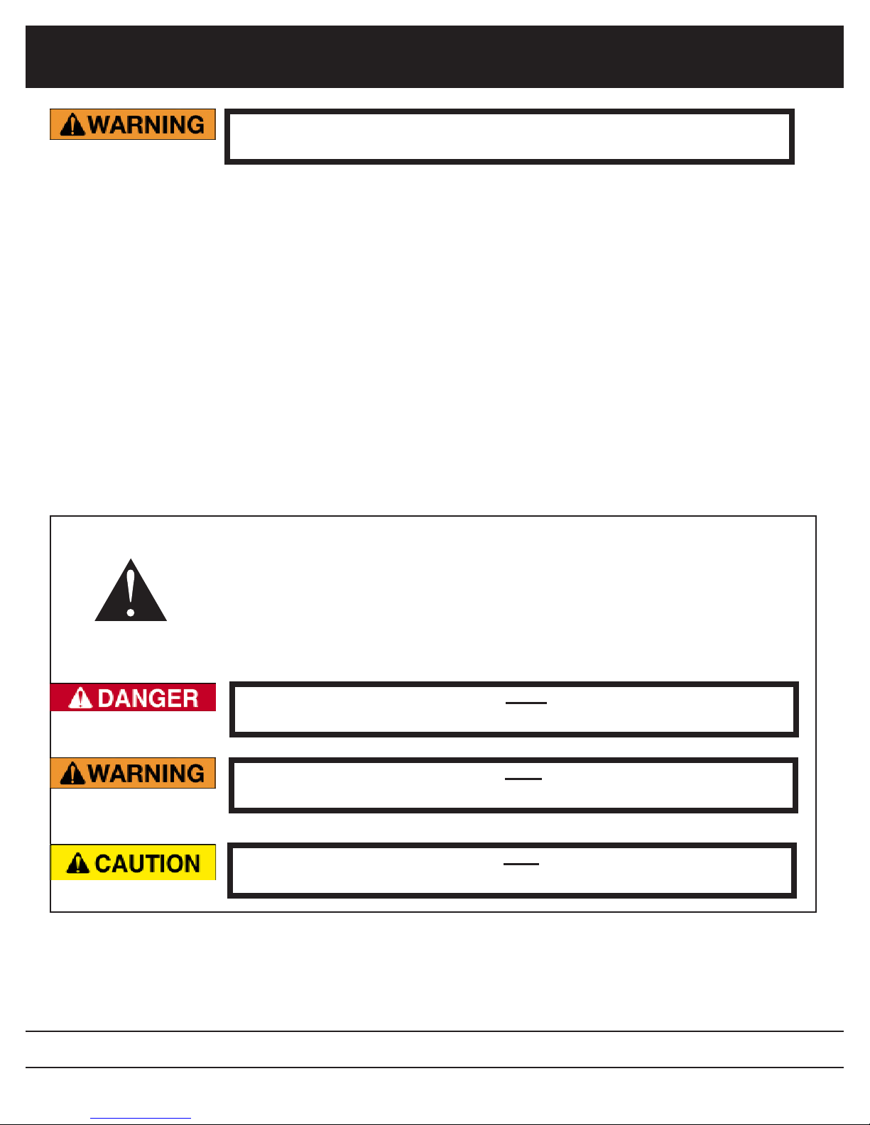
1.1 Safety Symbol Denitions
This manual provides the owners/operator with procedures for safe operation, maintenance and repair of your leaf collector. As with any machine,
there are hazards associated with their operation. For this reason safety is
emphasized throughout this manual. To highlight specic safety information
the following safety denitions are provided to assist the reader.
The purpose of safety symbols are to attract your attention to possible
dangers. The safety symbols, and their explanations, deserve your careful attention and understanding. The safety warnings do not by themselves
eliminate any danger. The instructions or warnings they give are not substitutues for proper accident prevention measures.
SYMBOL
MEANING
SAFETY ALERT SYMBOL: Indicates danger, warning or caution. At-
tention is required in order to avoid serious personal injury. May be used in
conjuction with other symbols or pictographs.
Disregarding this safety warning WILL result in serious equipment
damage, injury or possible death.
Disregarding this safety warning CAN result in serious equipment
damage, injury or possible death.
Disregarding this safety warning MAY result in minor or moderate
injury or property damage.
GVM-VAC
www.gvm-vac.com
10

SAFETY PRECAUTIONS
Read and understand this entire manual before operating, maintaining or repairing the leaf vacuum.
1.2 Do’s and Do Not’s:
This section contains some general safety precautions to do and not to do. This
is not an all inclusive list and and it is the responsibilty of the operator to have
proper training and use common sense in work situations.
DO NOT:
1. DO NOT operate, maintain or repair this unit without having fully read and
understood ALL the aspects of this manual.
2. DO NOT ride, sit or stand on unit at anytime.
3. DO NOT modify the leaf vacuum for any reasons to allow for riders.
4. DO NOT operate the unit in a state of disrepair.
5. DO NOT operate the unit with ANY guards or safety devices broken, miss-
ing, or inoperable.
6. DO NOT operate the unit without wearing proper safety equipment.
7. DO NOT operate this unit while under the inuence of any alcohol or medi-
cation.
8. DO NOT operate this unit if you have a record of mental instability or dizzi-
ness which could result in injury to yourself or others.
9. DO NOT operate this unit if you are under 18 years of age.
10. DO NOT operate this unit without fully inspecting the unit for any damage or
leakage.
11. DO NOT operate if the unit has any excessive vibration.
12. DO NOT operate unit with the inspection door limit switch damaged or miss-
ing.
13. DO NOT operate unit unless it is properly connected to a leaf collection box.
14. DO NOT operate unit unless it is properly attached to the tow vehicle.
15. DO NOT tow unit without using all the safety chains.
16. DO NOT tow unit with a damaged tongue.
17. DO NOT ll fuel tank with engine running. Allow engine to cool for 5 minutes
before refueling.
18. DO NOT operate unit if fuel is spilled or with fuel cap off.
19. DO NOT smoke or weld near the unit.
20. DO NOT run engine in an enclosed area.
21. DO NOT place hands or feet near moving or rotating parts.
22. DO NOT operate engine with an accumulation of grass, leaves or other de-
bris on the engine.
GVM-VAC
www.gvm-vac.com
11

SAFETY PRECAUTIONS
Do Not, continued;
23. DO NOT run engine with air cleaner removed.
24. DO NOT leave leaf machine unattended while in operation.
25. DO NOT park machine on steep grade or slope.
26. DO NOT vacuum a leaf pile without looking for foreign objects such as
metal, glass, plastic or large pieces of wood.
Do’s:
1. DO completely read and understand the owner’s manual before operat-
ing, maintaining or repairing the leaf collector.
2. DO follow engine and PTO manufacturer operating and maintenance
instructions.
3. DO check fuel lines and ttings frequently for cracks or leaks. Replace if
necessary.
4. DO completely inspect the unit before leaving the service garage.
5. DO check the tow tongue each day for cracks.
6. DO inspect and be attentive to what is being vacuumed.
7. DO check the impeller, liners and blower housing for cracks or holes
daily.
8. DO wear proper safety equipment as described in this manual.
9. DO watch for pedestrians, animals and other foreign material when vacu-
uming leaves.
10. DO replace any worn or missing safety stickers immediately.
GVM-VAC
www.gvm-vac.com
12

SAFETY PRECAUTIONS
1.3 Training:
Improper use of the GVM-Vac leaf collector CAN result in severe
personal injury or death. All personnel using this leaf vacuum must
be trained and qualied with all the operations, maintenance, repair
and safety procedures dened in this manual.
The warnings and procedures regarding safety in this manual are to be
used as a guideline only. It is impossible to cover all the events that
could happen in the vacuuming process. For this reason, it is vital that
the owner accept the responsibility to implement a training program that
will provide every operator or mechanic the basic skills and knowledge to
make good judgement in all situations.
This training program must include the entire scope of hazards, precautions and government regulations encountered in the vacuuming process.
The program should stress the need for regularly scheduled preventive
maintenance and detailed equipment safety checks.
It is strongly recommended that all training programs be documented to
ensure all operators and mechanics receive initial training on not just the
operation but the safety features of the leaf collector.
GVM-VAC
www.gvm-vac.com
13
SAFETY PRECAUTIONS
LH Side
5,6,7
Inside Pedestal
(2 of each)
1,9,6
on outside
of lid
11
1
13
12
1
8
13
13
10
4,3,2
RH Side
Front Rear
14
15
16
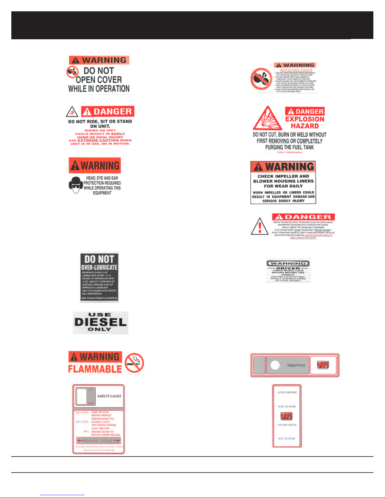
1.4 Safety Decals
shown at end
Decals
GVM-VAC
ITEM
NO.
1.
2.
3.
4.
5.
6.
7.
8.
9.
10.
11.
12.
13.
14.
15.
16.
PART
NUMBER
200182
200179
200181
200109
200055
200177
200059
200183
200178
200189
200180
200104
200120
200112
Danger--Do Not Open Cover While in Operation
Danger--Do Not Ride, Sit or Stand on Unit
Danger--Head, Eye and Ear Protection Required
Leaf Collector sticker
Do Not Over-Lubricate bearings
Use Diesel Only
Danger--Flammable
Do Not Engage PTO over 1,000 RPM
Danger--Rotating Parts
Danger--Explosion Hazard
Danger--Check Impeller and Liners Daily for Wear
Danger--Inspect Tow Bar for Damage
Warning--Check Lug nuts
GVM-Vac leaf collection systems sticker
Throttle decal
Safety Shut off-Ignition decal
DESCRIPTION
www.gvm-vac.com
of section
1.4
14
SAFETY PRECAUTIONS
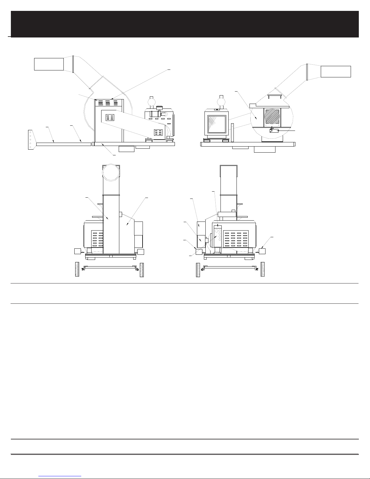
1.4 Safety Decals - Decal Layout for LCT60C/600/650/6000
1
2
3
4
9
10
11
12
5
6
7
8
13
14
15
16
GVM-VAC
www.gvm-vac.com
15

gure 1.5a
Serial Number Tag
VIN Number Tag
SAFETY PRECAUTIONS
1.5 VIN And Serial Number Locations
Thoroughly read and understand the safety and preoperating sections of this manual before starting the
engine.
Make sure each operator knows and understands the
load ratings of the towed vehicle and that he/she is
qualied to tow the vehicle.
The serial number tag and Vehicle Identication Number
(VIN) sticker is located in front of the unit to the right of
the the tongue. (See gure 1.5a).
Serial Number Tag
The VIN sticker gives the user critical information regarding the trailer speccations such as Gross Vehicle Weight
Rating (GVWR) which is the maximum allowable total
weight of the fully loaded trailer, including liquids, cargo
and the tongue weight of any towed vehicle, the GAWR
or Gross Axle Weight Rating which is the maximum allowable weight the axles are designed to carry. The tire
ination pressure is also on the sticker.
VIN Number Tag
Tire and Load Information
GVM-VAC
www.gvm-vac.com
16

2.0 PRE-OPERATING SECTION
Read and understand this entire manual before operating, maintaining or repairing the leaf vacuum.
Pre-Operating
2.0
Section
2.0 PRE-OPERATING SECTION
2.0 PRE-OPERATING SECTION
2.1 Instrument and Controls: .......................................................................................................18
2.2 Safe Operations: .....................................................................................................................20
2.3 Preparation For Operation ......................................................................................................22
2.4 Pre-Transport Checks .............................................................................................................23
2.5 Personal Protective Equipment and Clothing ........................................................................25
2.6 Work Site Preparation ............................................................................................................26
GVM-VAC
www.gvm-vac.com
17

Pre-Operating Section
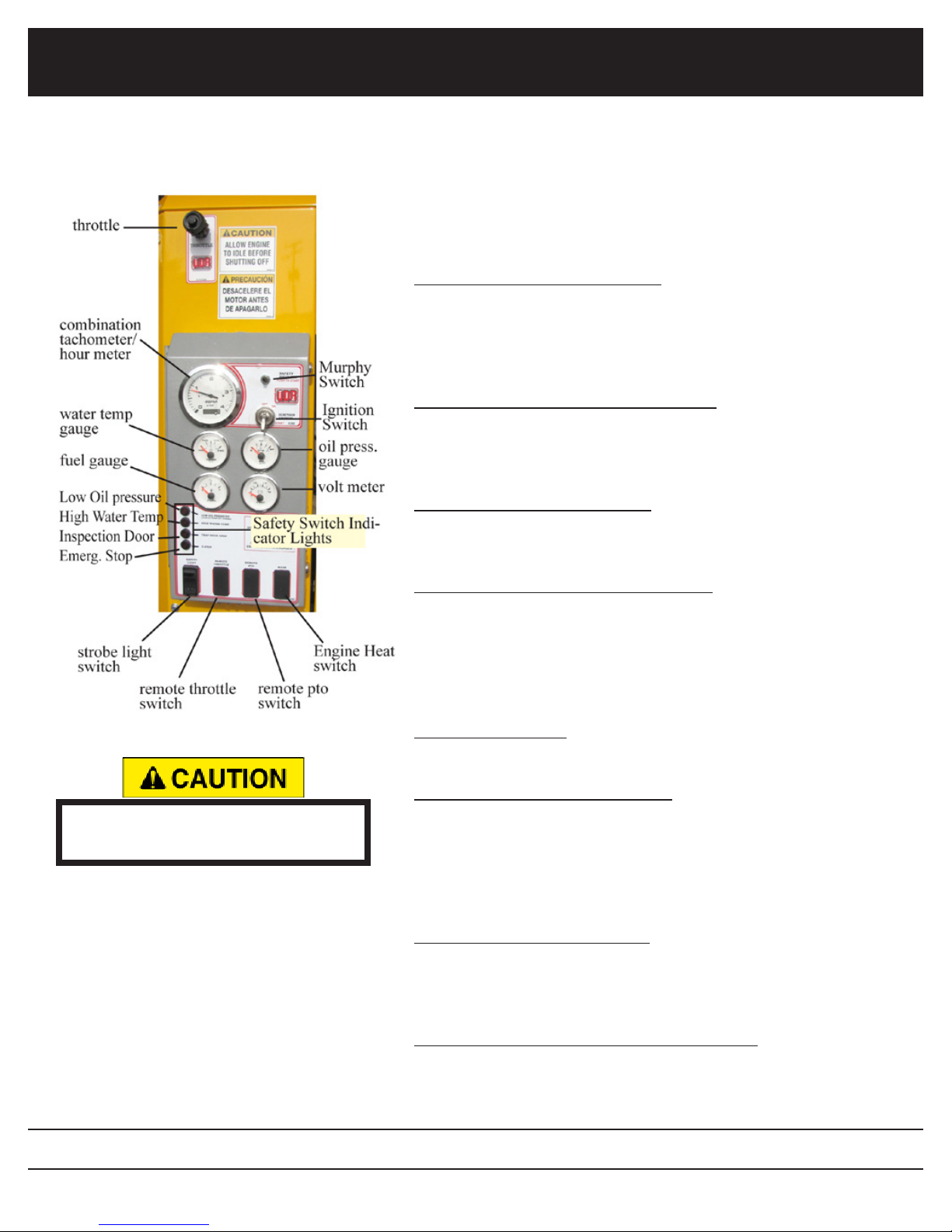
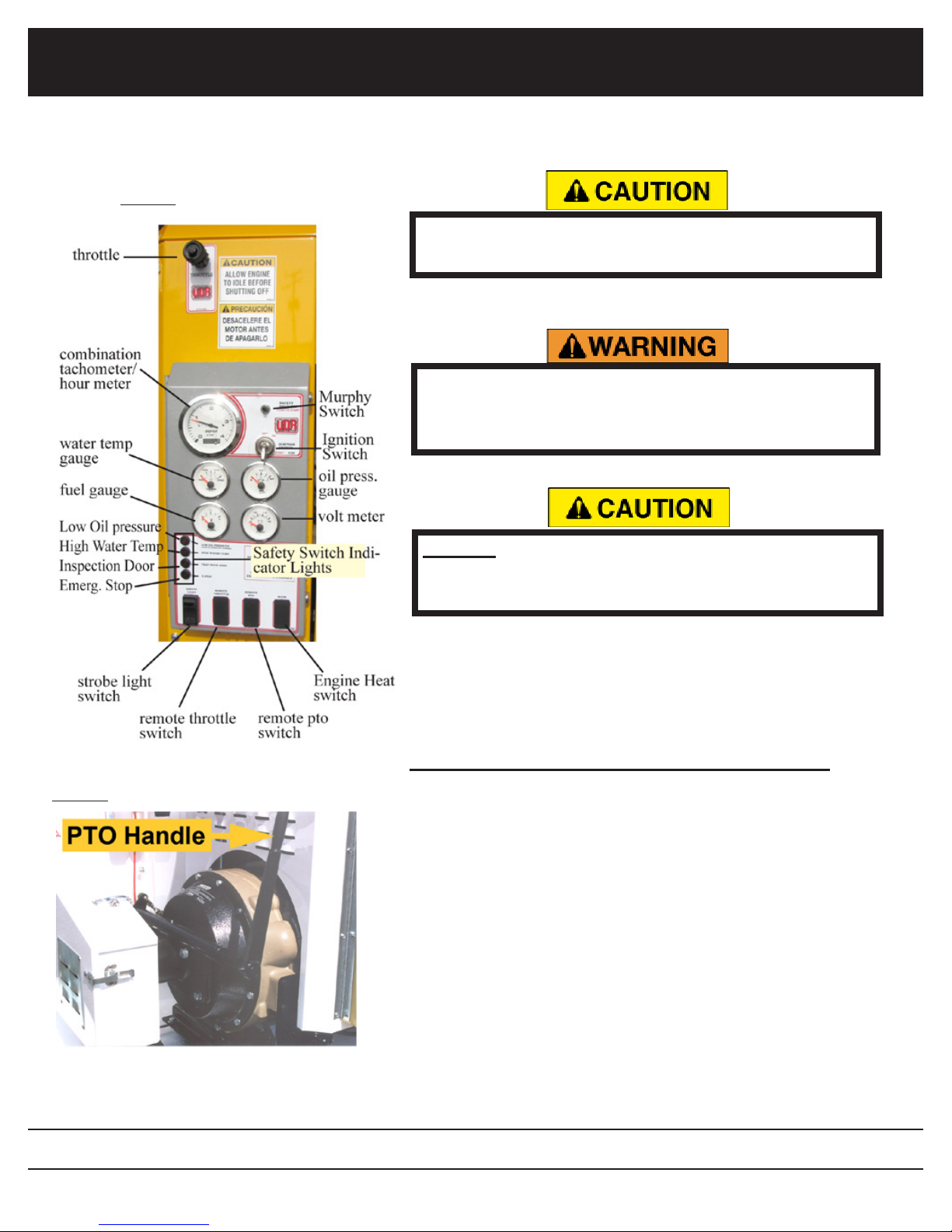
2.1 Instrument and Controls:
(Typical)
Ignition Switch:
Used to power the accessories and start the unit. Unit will not
start without Murphy switch depressed.
ACCESSORIES - rst position
STARTER ENGAGE - second position (springs return to rst
position)
Murphy Switch:
This switch overrides the low oil pressure and high temperature
cutoff control. This switch must be depressed before the starter
engages. After the engine starts, wait for oil pressure to rise
before releasing the button.
Throttle:
This control provides positive locking and vernier adjustment of
engine.
Combination Tachometer / Hour Meter:
This gauge indicates the engine r.p.m’s. The sender is located
on the tachometer. The hour meter is digital and indicates
the accumulated hours of the engine. This should be used to
schedule maintenance.
Always make sure the PTO is
disengaged before starting unit.
Volt Meter:
The gauge shows the status of the engine charging system.
When the charging system is operating properly it should read
approximately 14 volts. If the gauge reads below 13 volts, the
alternator is not charging the battery and the system should be
checked by a qualied technicican.
Oil Pressure Gauge:
Conrms and indicates the presense and pressure of engine
oil. If the gauge reads low, it should be checked by a qualied
technician.
Engine Temperature:
Indicates the engine coolant temperature. If the gauge reads
over 240 degrees the unit should be checked by a qualied
technician.
Hour Meter:
Indicates the accumulated hours of the the engine. This should
be used to schedule maintenance.
GVM-VAC
www.gvm-vac.com
18
Pre-Operating Section
(Typical)
2.1 Instrument and Controls, cont.:
SAFETY SWITCH INDICATOR LIGHTS
These lights work with the Murphy (safety) shut off switch. When
the light is on it indicates that the shut off switch has been tripped
and the light indicates which device caused the trip.
Low Oil Pressure Indicator Light:
When lit the engine has reached a low oil pressure reading and
has tripped (thus shut off the engine) the safety shut off (Muprhy)
switch . This light will illuminate when the engine is rst started
until engine oil pressure has been established.
High Water Temperature Indicator Light:
Indicates the engine coolant temperature has reached 225 degrees
and has tripped (thus shut off the engine) the safety shut off (Muprhy) switch.
Inspection Door Indicator Light:
Indicates that the limit switch located on the blower housing in-
spection door has been tripped (thus shut off the engine).
Always make sure the PTO is
disengaged before starting unit.
Emergency Stop Switch Indicator Light:
Indicates that the emergency stop switch (on the LCT650 only)
has been depressed, tripping the safety switch and shutting off the
engine.
ROCKER SWITCHES
Strobe Light Switch:
Turns the strobe light on or off
Remote Throttle Switch (optional):
Increases or decreases the engine throttle. Pressing and holding
the top of the switch increases the thottle. The longer the button is
pressed the higher the throttle is advanced. Pressing the bottom of
the switch decreases the throttle in the same manner as increasing
the throttle.
Remote PTO Switch (optional):
Engages or disengages the PTO. Pressing the top of the switch
engages the PTO while pressing the bottom of the switch disen-
gages the PTO.
GVM-VAC
Engine Heat Switch (Cummins engines only):
Press the top of the switch for 20 – 30 seconds initiates the glow
plug to aid in starting a cold engine.
www.gvm-vac.com
19

Pre-Operating Section
2.2 Safe Operations:
ALL personnel using, maintaining or servicing this unit must be
trained in all safety procedures outlined in this manual. Improper
or careless use of this equipment CAN result in personal injury or
death.
Operations shall be restricted to:
1. Properly trained, qualied and experienced operators and/or qualied and
experienced maintenance and test personnel.
2. Trainees under the direct supervision of qualied and experience
personnel.
3. Qualied and experienced maintenance and service personnel.
Operators who qualify to operate this equipment under the above restrictions shall also comply with the following physical requirements:
1. Have good vision and the ability to read and understand this manual as
well as all safety and operational decals on the equipment.
2. Be capable of hearing, with or without a hearing aid, at a level needed to
safely operate this equipment.
3. A record of mental stability with no history of epileptic seizures, dizziness,
or any other disability that may result in injury to himself or others.
If any of these requirements are not satised at any time, the person failing to
meet these requirements MUST NOT OPERATE THIS EQUIPMENT.
GVM-VAC
www.gvm-vac.com
20

Pre-Operating Section
2.2 Safe Operations (continued):
Additional Requirements:
1. Each operator must demonstrate competence to understand all safety
decals, operator’s manuals, safety codes, applicable government regulations, and all other information applicable to the safe and proper operation
of the leaf vacuum.
2. Each operator must demonstrate the ability to recognize an emergency
situation that may arise during vacuuming operations and the knowledge
and procedures to implement corrective action.
3. Each operator must demonstrate or provide evidence of qualicatation
and experience prior to operating the leaf vacuum.
4. Each operator must be able to recognize existing or potential problems regarding the mechanical integrity of the leaf vacuum and report any maintenance requirements to the supervisor in charge.
5. Each operator must wear the proper personal clothing and safety gear.
(Refer to SAFETY PRECAUTIONS Section 5.4)
6. Operators must not be physically or mentally fatigued.
7. Operators must not be under the direct or indirect inuence of alcohol
and/or drugs. This includes prescription drugs that could cause drowsiness, dizziness, or any other condition that would impair their ability to
operate or use this equipment in a safe manner.
GVM-VAC
www.gvm-vac.com
21
Pre-Operating Section
2.3 Preparation For Operation
Before your leaf vacuum is put into operation it is very important
to read and follow the procedures outlined in the engine owner’s
manual. (EOM).
For specic information regarding the following checks please refer to the
“Maintenance” section of this manual and the engine owner’s manual.
DISENGAGE the clutch and remove the negative battery cable before performing the following checks.
NEVER place any part of the body under or behind guards or any
other area in which you cannot see.
IMPORTANT CHECKS:
NOTE: The following checks contained in the next three sections should be
performed prior to leaving the storage area.
1. Check engine fuel, coolant and oil levels. (see EOM)
2. Check engine air lter
3. Check all bolts and nuts to ensure they are tight.
4. Check all controls for free and proper operation.
5. Check main drive belt (if equipped) for proper adjustment.
6. Inspect the fan blades to ensure that they are not bent , deformed, fatiqued
or cracked. Replace fan if any damage is present.
7. Inspect the intake hose ange to make sure it is connected correctly to the
blower housing.
8. Inspect the leaf vacuum frame and structure for any bent, broken, cracked,
missing or loose parts.
9. Check all guards to ensure they are undamaged, in place and properly
secured.
10. All decals must be in place and legible prior to operating the leaf vacuum.
See the decal section for decal replacement.
GVM-VAC
www.gvm-vac.com
22

Pre-Operating Section
2.4 Pre-Transport Checks
Failure to properly hitch the leaf vacuum to the tow vehicle, verify
the road worthiness of the leaf vacuum and the tow vehicle and
verify all equipment is properly stowed, may cause serious injury or
death to yourself or others.
TOW VEHICLE MUST have proper towing capacity for the leaf vacuum being towed. Check the tow vehicles operating manual for rated
capacity.
Do not tow the leaf vacuum unless all important checks listed below
are completed.
IMPORTANT CHECKS
1. Hitch is properly secured to tow vehicle and hose boom secured.
Frame must be level or the tongue slightly lower than the rear of the leaf
vacuum while towing to ensure proper weight distribution. The hitch may
have to be adjusted when towing with vehicles of varying tow hitch height.
2. Safety chains installed correctly.
3. Chains routed under trailer tongue in an “X” pattern between tow vehicle and
trailer.
4. Slack in chain should be adjusted to permit turning but should not be dragging on the ground.
5. Connect trailer wiring to the tow vehicle and ensure that all trailer lighting is
operating properly.
6. Ensure that the safety breakaway switch is functioning properly and attached
securely to the tow vehicle. Allow enough slack to ensure that vehicle turns
will not activate the safety breakaway switch. NOTE: Follow manufacturers
procedure to ensure tow vehicles brake control box is properly adjusted.
7. Check the general condition of the tires, tire pressure and ensure that all lugnuts are securely fastened.
GVM-VAC
www.gvm-vac.com
23

Pre-Operating Section
2.4 Pre-Transport Checks (continued):
8. Visual examination of the leaf vacuum frame, suspension and structure
to determine if all components are correctly positioned and secured for
travel.
9. Check the intake hose boom to verify that it is securely fastened to the leaf
vacuum and can not swing free. (if equipped).
10. Verify there are no loose tools or materials on the trailer, inside the intake
and exhaust hoses, or inside the engine sheet metal.
11. Check all cones, wheel-chocks, signs or other support tools and materials
to ensure proper stowage.
GVM-VAC
www.gvm-vac.com
24
Pre-Operating Section
2.5 Personal Protective Equipment and Clothing
Always wear proper safety equipment as outlined below, not wearing such equipment CAN result in serious personal injury or possible death.
IMPORTANT CHECKS:
Anyone operating the leaf vacuum equipment MUST wear appropriate protective equipment and clothing to protect them from injury during operations.
PROTECTIVE EQUIPMENT:
1. Head Protection: Hard hats without under-chin strapping.
2. Eye Protection: Wraparound goggle type eye protection held in place
with an elastic band around the head or a hard hat mounted face shield,
which provides full protection of the face.
3. Eye protection must meet ANSI Z87.1 standards.
4. Hearing Protection: plug type or “muff type” ear protection should be
worn at all times while operating the unit.
5. Breathing Protection: Paper lter type dust masks should be worn to
protect from dirt and dust particles during the vacuuming process.
6. Reective Vests: Highly visible vests should be worn so motorists can
see see the operator in all weather and lighting conditions.
7. Work Gloves: Gloves should be worn to protect the hands and wrists
from debris.
8. Steel Toed Boots: should be worn to protect the feet.
Work clothes MUST be close tting, but not restrictive of movement, without any loose parts that could be entangled in any parts
of the leaf vacuum. This includes items such as jewelry, chains
and backpacks.
GVM-VAC
www.gvm-vac.com
25
Pre-Operating Section
2.6 Work Site Preparation
Never place any part of the body under or behind guards or any
other visually obscured area.
Making sure the leaves are clear of possible dangerous material is
critical to safe vacuuming. Vacuuming up metal, glass, rocks or
other dangerous material CAN cause serious damage to the equipment or personal injury.
The following guidelines must be followed to insure safety.
1. An inspection of the leaves to be vacuumed must be done prior to the
vacuuming process. We realize that it is impossible to completely inspect
every inch of leaves being vacuumed, but it is imperative that all leaves be
inpsected for obvious dangerous material before vacuuming.
2. The operator should never be in the line of trafc, the operator should work
on the shoulder whenever possible.
3. The operators should place cones or other barriers to provide adequate
warnings to vehicles and pedestrians that vacuuming is in progress.
4. Strobe lights on the leaf vacuum and on the tow vehicle should be on at all
times for high visibility.
5. Conrm that all operators are wearing proper clothes and personal protec-
tive equipment.
6. Restrict all personnel, except the operator from the area near the leaf vacuum. DO NOT allow pedestrians, children or animals near the work area.
7. Make sure that the exhaust hose (if equipped) ts properly into the box
container so that all debris is blown into the box container.
GVM-VAC
www.gvm-vac.com
26

3.0 OPERATING SECTION
Read and understand this entire manual before operating, maintaining or repairing the leaf vacuum.
3.0 OPERATING SECTION
3.0 OPERATING SECTION
3.1 Starting Engine .................................................................................................................... 28
3.2 Engaging the PTO ............................................................................................................... 30
3.3 Fluid Drive Coupler (if equipped) ...................................................................................... 32
3.4 Vacuuming Leaves .............................................................................................................. 33
GVM-VAC
www.gvm-vac.com
27
gure 3a
Operating Section
3.1 Starting Engine
Always make sure the PTO is disengaged before
starting unit. (See gure 3b)
Thoroughly read and understand the safety and
pre-operating sections of this manual before staring the engine.
gure 3b
DO NOT start the engine in an enclosed building.
Proper ventilation is required before starting the
engine.
Review the Engine Operating Manual supplied with your
leaf vacuum for specic start-up, maintenance and operating instructions. It is especially important to review break-in
service procedures for brand new units.
Starting Procedure (refer to gures 3a and 3b):
1. Perform all the pre-starting, pre-operating checks outlined in the EOM and in this manual.
2. Make sure the PTO is disengaged as shown in gure
3b.
3. Turn the throttle control (g. 3a) counter-clockwise 2
revolutions.
GVM-VAC
4. Depress and hold the Murphy switch while starting.
www.gvm-vac.com
28

gure 3a
Operating Section
3.1 Starting Engine, continued;
5. IMPORTANT: Do not operate the starter for more
than 30 seconds at a time. To do so may overheat the
starter. If the engine does not start the rst time, wait
at least 2 minutes before trying again. If the engine
fails to start after 4 attempts, see the trouble shooting
section of the EOM and this manual.
6. Turn the ignition switch all the way to the right, when the
engine starts release the ignition switch. It should spring
back to the rst position.
7. IMPORTANT: If the ignition switch is released before
the engine starts, wait until the starter and the engine
stop turning before trying again. This will prevent
possible damage to the starter and/or ywheel.
gure 3b
8. After the engine starts, continue to hold the Murphy Switch
in until the oil pressure gauge reads at least 15 psi. The
Murphy shut off switch will not allow the engine to operate below this level. If the gauge does not rise above 15
psi withing 5 seconds, stop the engine and determine the
cause. Normal operating oil pressure is 50 psi with oil at
normal operating temperature.
9. Check all gauges for normal engine opreration. If op-
eration is not normal, stop the engine and determine the
cause.
10. IMPORTANT: To assure proper lubrication, operate the
engine at or below 1200 rpm with no load for 1 -2 minutes. Extend this period 2 - 4 minutes when operating
at temperatures below freezing.
11. Watch the coolant temperature gauge. Do not place en-
gine under load until it is properly warmed up. The normal
engine coolant temperature range is 180 - 202 degrees F.
GVM-VAC
www.gvm-vac.com
29
Operating Section
gure 3b
gure 3c
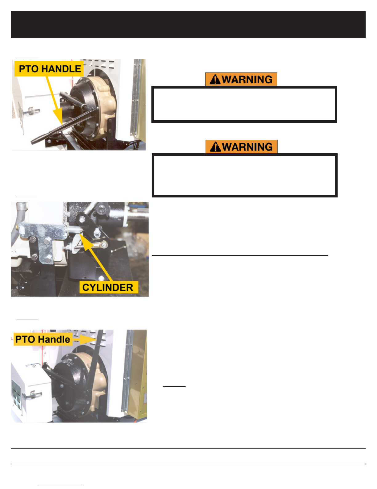
3.2 Engaging the PTO
Thoroughly read and understand the safety and
pre-operating sections of this manual before staring the engine.
PTO shown disengaged
Make sure the intake hose is properly attached
and make sure the front of the hose is clear of
any objects which could be inadvertently vacuumed during the PTO engagement process.
Review the Engine Operating Manual supplied with your leaf
vacuum for specic start-up, maintenance and operating instructions. It is especially important to review break-in service
procedures for brand new units.
gure 3d
safety assist cylinder
PTO shown fully engaged
Engaging the PTO (refer to gures 3b, 3c and 3d):
1. Perform all the pre-starting, pre-operating checks outlined in
the EOM and in this manual.
2. Start the engine as previously discussed in this manual and
in the EOM.
3. Once the engine has been allowed to thoroughly warm up
(engine temperature gauge should read at least 180 degrees) pull the throttle control until the engine reaches 1000
rpm.
4. Grasp the PTO handle (g. 3b) and slowly raise the handle.
NOTE: Some units have a PTO assist cylinder which engages the PTO at a specic speed in order to properly engage
the PTO. Because of this the PTO handle only needs to
be raised slightly, then the assist cylinder will take over and
engage the PTO automatically. (g. 3c)
GVM-VAC
www.gvm-vac.com
30
 Loading...