

Service Manual for:
<KA
Global
HZg^Zh
Wheelchair Lifts
02
33222
"Providing Access to the World"
International Corporate Hdqrs: P.O. Box 310 Winamac, IN 46996 USA
1-800-THE LIFT
34179 Rev. A
December
2007
®
(574) 946-6153 FAX: (574) 946-4670
Patent #5,261,779
Patent #5,261,779
Patent #6,065,924
Patent #6,065,924
Patent #6,238,169
Patent #6,238,169
Patent #6,464,447
Patent #6,464,447
Patent #6,599,079
Patent #6,599,079
Patent #6,739,824
Patent #6,739,824
Patent #6,837,670
Patent #6,837,670
Patents Pending
Patents Pending
A
R N I N G
W
Man
ual
®
®
Read manual
before installing
or servicing lift.
Failure to do so
may result in
serious bodily
injury and/or
property damage.
Braun GVL Series
Braun GVL Series
GVL936IB3144
e5*72/245*95/54*0110*00
1-800-THE LIFT™
BRAUNLIFT.COM™
The Braun Corporation
Not For Sale in U.S. - For Export Only
Max. Lifting Capacity - 800 lbs.
PATEN T
PENDING-
5,261,779-6,065,924-6,238,169-6,46
4,447-6,599,079-6,692,217-6,739,824
MFG DATE
62 14CF
PUMP CODE CYLINDER
02-00025
SERIAL NUMBER
06/06/07
OWNER'S WARRANTY REGISTRATION
PURCHASED FROM
DATE INSTALLED
NAME
ADDRESS
CITY
TELEPHONE
TO VALIDATE WARRANTY
REGISTRATION CARDS MUST BE RETURNED TO THE BRAUN CORPORATION.
OWNER
STATE ZIP
Congratulations
We at The Braun Corporation wish to express our fullest appreciation
on your new purchase. With you in mind, our skilled craftsmen have designed and
assembled the finest lift available.
This manual provides service-related material. Refer to the Quick Reference
Installation Sheet for installation instructions, operating instructions and maintenance
procedures.
Braun Global Series™ lifts are built for dependability and will provide years of
pleasure and independence as long as the lift is installed and serviced as specified by
a Braun certified technician, and the lift is operated by an instructed person.
Sincerely,
THE BRAUN CORPORATION
Ralph W. Braun
Chief Executive Officer
Warranty and Registration Instructions
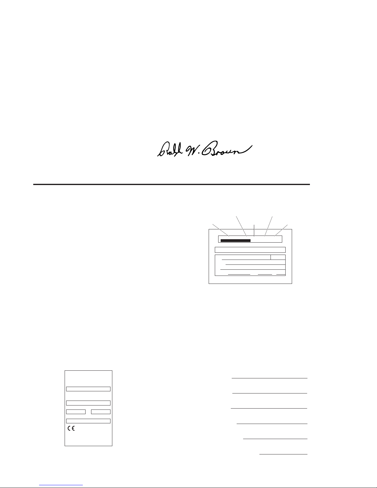
Immediately upon receiving the lift, examine the
unit for any damage. Notify the carrier at once
Series No. Pump Code
Serial No.Model No. Cylinder Code
with any claims.
GVL936IB3144 02-00025 62 14CF
Two warranty/registration cards (shown right) are
located in the lift-mounted manual storage pouch.
The sales representative must process one of the
cards. The consumer must fill out the other card
and mail it to The Braun Corporation. The warranty is provided on the back cover of this manual.
The warranty cards must be processed to
Sample Warranty/Registration Card
activate the warranty.
Two Braun Serial No./Series No. identification tags (shown below) are posted on the lift.
One I.D. tag is posted on the opposite pump side vertical arm. A second I.D. tag is located
on the opposite pump side tower. Both I.D. tags provide the product identification information provided on the warranty/registration card. Record the information in the space
provided (or document on a copy). This information must be provided when filing
a warranty claim or ordering parts.
Model No.
Sample Serial No./Series No. Identification Tag
Series No.
Serial No.
Pump Code
Cylinder Code
Date of Manufacture

Contents
Troubleshooting and Maintenance
Lift Terminology............................................................. 2
Switch and Sensor Locations ..................................... 3
Platform Fold Pressure Adjustment ............................ 4
Platform Angle Adjustment ......................................5-6
Tower Microswitch Adjustment .................................... 7
Lubrication Diagram ...................................................... 8
Maintenance and Lubrication Schedule................. 9-12
Lift Electrical Schematic ............................................ 13
Lift Wiring Diagram .................................................... 14
Hydraulics
Hydraulic Schematic .................................................. 15
Hydraulics Parts List .................................................. 16
Hydraulics Diagram .................................................... 17
Repair Parts
Pump Module
Pump Module Parts List ....................................... 18
Pump Module Diagram ......................................... 19
Lift Exploded Views and Parts Lists
Base Plate Assembly .......................................20-22
Top Parallel Arm Assembly ................................... 23
Bottom Parallel Arm Assembly ........................ 24-25
Hydraulic Cylinder Assembly - Main .................... 26
Vertical Arm Assembly .....................................27-28
Handrail Assembly ................................................. 29
Platform Assembly - Inboard ................................30-32
Platform Assembly - Outboard .............................33-35
Inner Roll Stop Assembly .................................36-38
Page 1
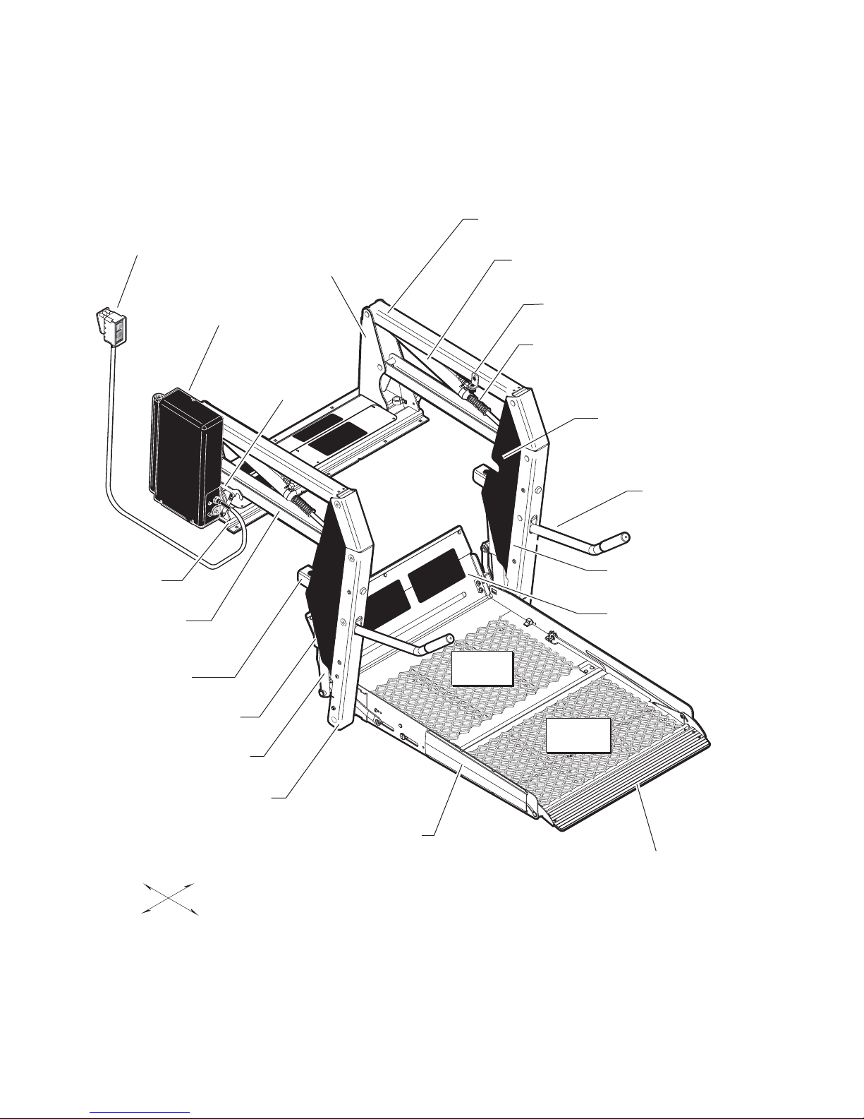
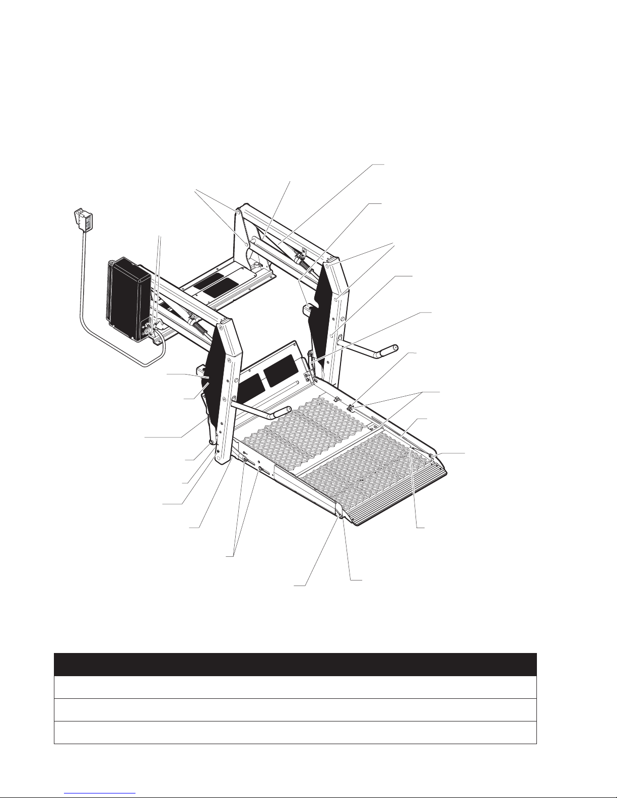
Lift Terminology
Hand-Held
Pendant
Control
D
OL
F
)
D
IN
L
(
O
UNF
T)
(OU
UP
DOWN
Base Plate
Bottom Parallel
Arms (2)
Pump Module
(Rear)
Towers (2)
Lift-Tite™
Latches (2)
Top Parallel Arms (2)
Main Cylinders (2)
Adjustable Quiet-Ride Stow Blocks (2)
Unfold Assist Compression Springs (2)
Vertical Arm Covers (4)
Handrails (2)
Opposite Pump Side
Vertical Arm
Inner Roll Stop
Saddle (2)
Upper Fold Arm (2)
Lower Fold Arm (2)
Inboard
Left
Inboard
Platform
Outboard
Platform
Pump Side
Vertical Arm
Platform Side Plates (2)
Outer Barrier
Right
Outboard
Page 2
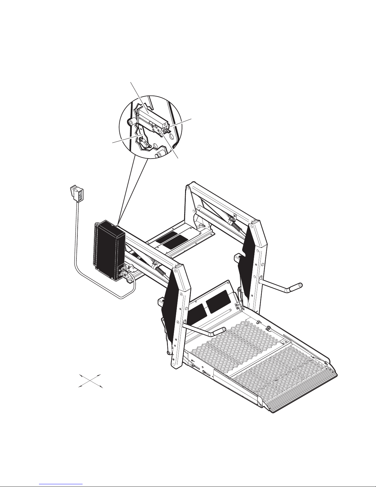
*Partial Fold
Microswitch Assy.
32735RA
D
FOL
D
(IN)
UNFOL
T)
(OU
UP
DOWN
Switch and Sensor Locations
*Up & Unfold
Microswitch Assy.
975-3121A
*Up Microswitch
*Unfold
Microswitch
Inboard
Left
Right
Outboard
*Note: Mirror image for
right (front) pump lifts.
Page 3
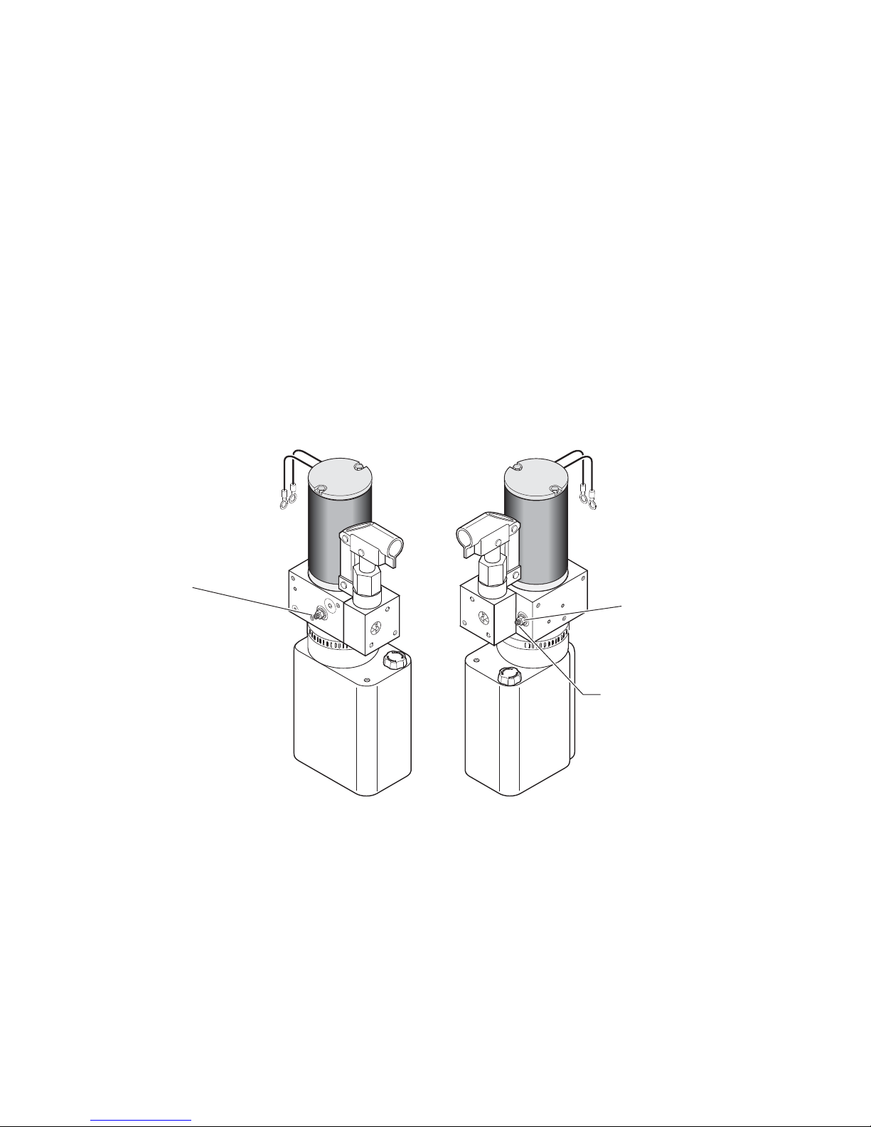
Platform Fold Pressure Adjustment
1. Position the platform at the floor level loading position.
2. Loosen the hex nut on the adjustment screw (do not remove hex nut).
3. Turn the adjustment screw counter clockwise until the platform does not fold when the Fold button is
pressed.
4. Turn the adjustment screw clockwise in 1/4 turn increments and press the Fold button until the platform folds completely (Note: Return the platform to floor level position after each attempt to fold the
platform).
5. Turn the adjustment screw an additional 1/8 turn after the platform folds successfully.
6. Tighten the hex nut without moving the adjustment screw.
7. Verify the platform will not stow while occupied.
DO NOT adjust this valve!
(Located on back side of pump block)
Note: Secure adjustment
screw and tighten hex
nut following adjustment.
Platform Fold
Adjustment
Allen Screw
Page 4
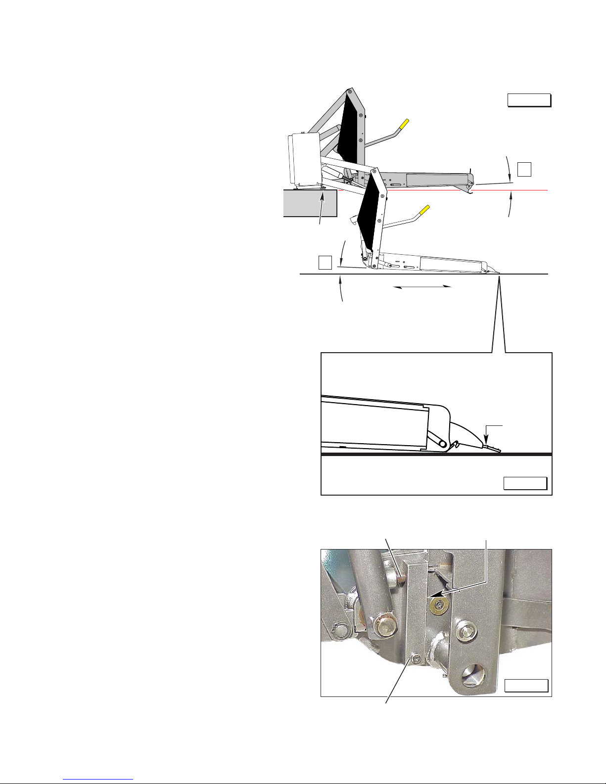
Platform Angle Adjustment
Adjustments to platform angle
may be required. Adjusting the
platform angle based on the relationship of the platform at ground
level directly affects the angle of
the platform when positioned at
floor level.
Unfold the lift and visually examine the angle of the platform
when positioned at floor level.
Lower the platform fully and note
the angle of the platform when it
reaches ground level also.
The platform angle must be
adjusted so there is a balance
between the angle at both positions (equal amount of angle).
Angle A should equal Angle B
as shown in Figure A.
Note: The outboard end of the
platform must contact the ground
first to ensure the spring-loaded
outer barrier unfolds fully. See
Figure B.
Adjustment Procedures:
Adjustment Allen screws are
provided on each side of the lift
platform for adjusting the platform
angle. See Figure C. Turn the
adjustment screw clockwise to
raise the outboard end of the
platform. Turn the adjustment
screw counterclockwise to
lower the outboard end of the
platform. Note: Both adjustment screws must be adjusted
equally. Ensure both stop
blocks are making full contact
with the vertical arms. Apply
®
Loctite
following adjustment.
to adjustment screws
Angle A
equals
Angle B.
Figure A
✓
A
Floor
Level
Shim
B
Inboard
Approximately
1" Clearance
Platform Angle Adjustment Screw Inside edge of vertical arms
Outboard
Barrier
must
unfold
fully.
Figure B
Floor Level Adjustment:
Following platform angle adjustment, set platform floor level
positioning as detailed in Tower
Microswitch Adjustments.
Figure C
Stop Block
Page 5
Platform Angle Adjustment
W
A
RNING
Automatic Floor Level Positioning: GVL936
Series lifts feature automatic floor level positioning.
This feature eliminates the need for the lift operator
to position and stop the platform at vehicle floor
level when unfolding the platform from the stowed
position and when raising the platform from ground
level.
Floor Level Adjustments: Tower 1 (Unfold) and
Tower 2 (Up) microswitches control platform and
bridge plate positioning. Ensure floor level adjustments are correct as outlined on page 7. Adjust
microswitches as needed only.
Floor Level Guidelines: When adjusting microswitches, bridge plate positioning and platform stop
block positioning must be viewed. A combination of
adjustments may be required to achieve a proper
balance. See Bridge Plate Positioning and Stop
Blocks below.
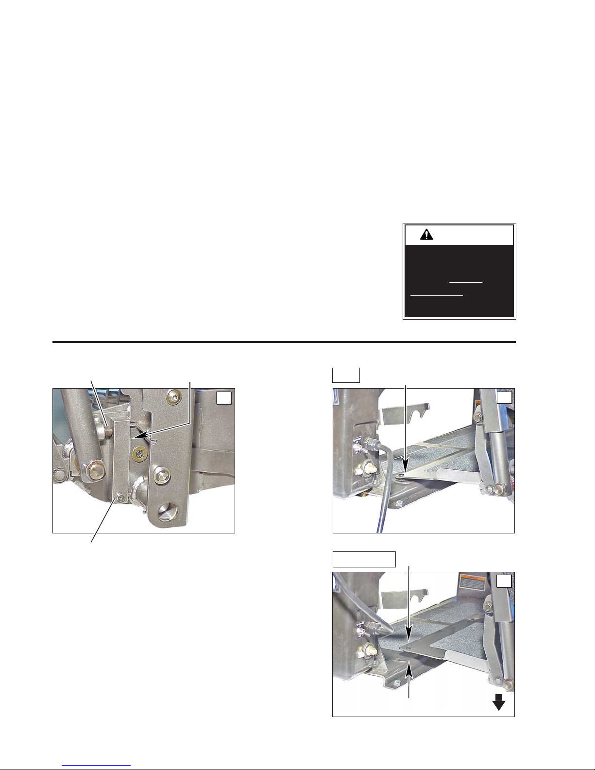
Platform Angle
Adjustment Screw
Inside edge of
vertical arms
Platform Angle Adjustments: Check platform
angle as outlined on page 5 when adjusting microswitches.
Adjustment Verification: Following the outlined
adjustment procedures, check floor level position
from stow position and from below floor level posi-
tion. The platform must stop automatically at floor
level when unfolding from stow position and when
raising from below floor level position. From the
stowed position, press the UNFOLD switch and hold
until the platform stops
at floor level. Once
stopped, ensure the
lift will fold when the
pendant FOLD switch
is pressed. Adjust the
switches as needed
per the guidelines in
Figure E.
Bridge plate resting solidly on
OK
base plate.
Improper microswitch
adjustment may
result in serious
bodily injury and/or
property damage.
A
Stop Block
Stop Blocks: The platform stop blocks
(one per side) must be making full contact
with the vertical arms when the platform is at
floor level. See Photo A. Improper adjust-
ment of screw positioning can result in
lift damage.
Bridge Plate Positioning: The bridge
plate should rest solidly on the base plate.
There should be a smooth (level) transition
between the platform, bridge plate and the
base plate. Refer to Photos B and C.
WRONG
B
Platform and bridge plate level.
Gap not permitted.
C
Platform too low.
Page 6
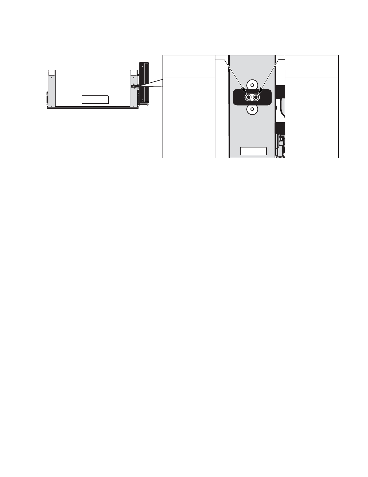
Tower Microswitch Adjustment
TOWER2TOWER
1
32942
Figure D
Note: Review
adjustment
procedures
below and
adjust as
needed only.
Note: Left
(rear) pump
lift depicted.
Right (front)
pump lift is
a mirrored
image.
Microswitch Adjustment Instructions:
Tower 1 (Unfold) Switch Adjustment:
Floor Position from Stow
1. Position platform at the fully stowed
position using the manual hand pump or
pendant control.
Tower 2
(Up)
Microswitch
Turn adjustment
screw counterclockwise to stop
the platform raise
function sooner.
Turn adjustment
screw clockwise
to allow the
platform to raise
further.
Tower 1
(Unfold)
Microswitch
Turn adjustment
TOWER
2
TOWER
1
32942
screw clockwise to stop the
platform unfold
function sooner.
Turn adjustment
screw counterclockwise to allow the platform
Figure E
to unfold further.
Tower 2 (Up) Switch Adjustment:
Floor Position from Below Floor
1. Lower platform a minimum of 6" below floor
level position using the manual hand pump
or pendant control.
2. Turn switch adjustment screw clockwise 3
full turns.
3. Press pendant UNFOLD switch (continue
pressing switch until platform stops unfolding).
4. When platform stops unfolding, turn switch
adjustment screw counterclockwise while
pressing the pendant UNFOLD switch.
Platform position will change. Repeat
adjustment until criteria below is met.
Proper Adjustment Criteria:
• The bridge plate should rest solidly on
the base plate (minimum of 1" overlap).
There should be a smooth (level) transition between the platform, bridge plate
and the base plate. See Photos B and C.
• The platform stop blocks (one per side)
must be making full contact with the
vertical arms when the platform is at floor
level. See Photo A.
2. Turn switch adjustment screw counterclockwise 3 full turns.
3. Press pendant UP switch (continue pressing switch until platform stops).
4. When platform stops, turn switch adjustment screw clockwise while pressing the
pendant UP switch. Platform position
will change. Repeat adjustment to meet
criteria listed in Tower 1 Switch "Proper
Adjustment Criteria" at left.
Adjustment Verification
Following adjustment procedures, verify
proper adjustment as detailed at left. Adjust the switches as needed per the guidelines in Photo A.
Page 7
Parallel Arm
Pivot Pin Bearings (16)
™
OLD
F
)
D
N
I
(
OL
UNF
UT)
O
(
UP
N
OW
D
Lift-Tite
Dampening Springs
Latch
(2 springs - 4 Points) LO
Saddle Support Bearings (8)
LO
Upper Fold Arm Pivot Points (2)
LO
Upper and Lower Fold Arm
Contact Area (2)
LG
Lower Fold Arm Pivot Points (2)
LO
Platform Fold Link Bearings (4)
LO
Lift-Tite™ Latch Rollers (2)
LO
Platform Pivot Pin Bearings (4)
LO
Maintenance and Lubrication
Lubrication Diagram
™
Lift-Tite
(Tower Pivot Points - 2)
LO
Latches
LO
Saddle Bearing
Hydraulic Cylinder
Pivot Bushings (8)
LO
Buttons (4)
DE
Parallel Arm
Pivot Pin Bearings (16)
LO
Handrail Pivot Pins (2)
LO
Inner Roll Stop Lever
Bearings (2) and Slots (2)
LO
Platform Fold Gear Rack (2) and
Gear Link Assembly Teeth (2)
DE
Gear Link Assembly
Bearings (4)
LO
Platform Side Plate Slots (2)
LG
Outer Barrier
Arm Slots (2)
LG
Outer Barrier
Latch Foot Bearings (2)
LO
Platform Fold Gear Rack Bearings (4)
LG
Outboard Platform Bearings (2)
See the Maintenance/Lubrication Schedule for recommended applications per number of cycles.
Specified (recommended) Available Braun
Lubricant Type Lubricant Amount Part No.
LO - Light Oil
DE - Door-Ease
LG - Light Grease
Light Penetrating Oil LPS2, General Purpose 11 oz.
(30 weight or equivalent) Penetrating Oil Aerosol Can
Stainless Stick Door-Ease 1.68 oz.
Style (tube) Stick (tube)
Light Grease Lubriplate 14 oz.
(Multipurpose) Can
Page 8
LG
Outer Barrier Arm
Pivot Points (2)
LO
15807
15806
15805
W
A
RNING
Maintenance and Lubrication Schedule
Proper maintenance is necessary to ensure safe,
troublefree operation. Inspecting the lift for any
wear, damage or other abnormal conditions should
be a part of all transit agencies’s daily service
program. Simple inspections can detect potential
problems.
The maintenance and lubrication procedures specified in this schedule must be performed by a Braun
authorized service representative at the scheduled
intervals according to the number of cycles.
Braun dual parallel arm lifts are equipped with hardened pins and self-lubricating bushings to decrease
wear, provide smooth operation and extend the
service life of the lift.
When servicing the lift at the recommended intervals, inspection and lubrication procedures specified
in the previous sections should be repeated. Clean
the components and the surrounding area before
applying lubricants. LPS2 General Purpose
Penetrating Oil is recommended where Light Oil is
called out. Use of improper lubricants can attract
dirt or other contaminants which could result in wear
or damage to the components. Platform components exposed to contaminants when lowered to the
ground may require extra attention.
Lift components requiring grease are lubricated dur-
ing assembly procedures.
When these components
are replaced, grease must
be applied during installation procedures. Specified
lubricants are available from
The Braun Corporation.
Maintenance and
lubrication procedures
must be performed as
specified by an
authorized service
All listed inspection, lubrica-
tion and maintenance procedures should be repeated
at “750 cycle” intervals
following the scheduled
“4500 Cycles” maintenance.
technician. Failure to
do so may result in
serious bodily injury
and/or property
damage.
These intervals are a general guideline for scheduling
maintenance procedures and will vary according to lift
use and conditions. Lifts exposed to severe conditions
(weather, environment, contamination, heavy usage,
etc.) may require inspection and maintenance procedures to be performed more often than specified.
Discontinue lift use immediately if maintenance and
lubrication procedures are not properly performed, or if
there is any sign of wear, damage or improper operation.
Contact your sales representative or call The Braun
®
Corporation at 1-800-THE LIFT
. One of our national
Product Support representatives will direct you to an
authorized service technician who will inspect your lift.
750
Cycles
continued
Outer barrier arm pivot points (2)
Outer barrier arm slots (2)
Gear link assembly bearings (4)
Gear link assembly teeth (2)
Outboard platform bearings (2)
Platform fold link bearings (4)
Platform fold gear rack bearings (4)
Platform fold gear rack teeth (2)
Lift-Tite™ latches (tower pivot points - 2)
™
Lift-Tite
points (2 springs - 4 points)
Inspect Lift-Tite
or damage (bent, deformed or misaligned), positive
securement and proper operation
Inspect outer barrier for proper operation
latch gas (dampening) spring pivot
™
latches and gas springs for wear
Apply Light Oil - See Lubrication Diagram
Apply Light Grease - See Lubrication Diagram
Apply Light Oil - See Lubrication Diagram
Apply Door Ease - See Lubrication Diagram
Apply Light Grease - See Lubrication Diagram
Apply Light Oil - See Lubrication Diagram
Apply Light Grease - See Lubrication Diagram
Apply Door Ease - See Lubrication Diagram
Apply Light Oil - See Lubrication Diagram
Apply Light Oil - See Lubrication Diagram
Resecure, replace damaged parts or otherwise
correct as needed. Note: Apply Light Grease to
™
Lift-Tite
Correct or replace damaged parts.
latch tower pivot point if replacing latch.
Page 9

continued
Maintenance and Lubrication Schedule
Inspect outboard barrier feet for proper operation,
positive securement and detached or missing
torsion spring
Correct, replace damaged parts and/or relubricate.
750
Cycles
Inspect platform fold gear rack and gear link assembly teeth for foreign objects, wear or damage (bent, deformed or misaligned), positive
securement and proper operation
Inspect lift for wear, damage or any abnormal
condition
Inspect lift for rattles
Perform all procedures listed in previous sections also
Outer barrier latch foot bearings (2)
Upper/lower fold arm contact areas (2)
Platform pivot pin bearings (4)
Upper fold arm pivot points (2)
Lower fold arm pivot points (2)
Inner roll stop lever bearings (2)
Inner roll stop lever slot (2)
Remove foreign objects, replace damaged parts
and resecure as needed
Correct as needed.
Correct as needed.
Apply Light Oil - See Lubrication Diagram
Apply Grease (synthetic) to contact areas between upper/lower fold arms. See Lubrication
Diagram
Apply Light Oil - See Lubrication Diagram
Apply Light Oil - See Lubrication Diagram
Apply Light Oil - See Lubrication Diagram
Apply Light Oil - See Lubrication Diagram
Apply Light Oil - See Lubrication Diagram
1500
Cycles
continued
Saddle support bearings (8)
Parallel arm pivot pin bearings (16)
Handrail pivot pins (2)
Hydraulic cylinder pivot bushings (8)
Platform side plate slots (2)
Inspect Lift-Tite™ latch rollers for wear or damage,
positive securement and proper operation (2)
Inspect inner roll stop for:
• Wear or damage
• Proper operation. Inner roll stop should just rest
on top surface of the base plate.
• Positive securement (both ends)
Inspect handrail components for wear or damage,
and for proper operation
Inspect microswitches for securement and proper
adjustment.
Make sure lift operates smoothly
Apply Light Oil - See Lubrication Diagram
Apply Light Oil - See Lubrication Diagram
Apply Light Oil - See Lubrication Diagram
Apply Light Oil - See Lubrication Diagram
Apply Light Grease - See Lubrication Diagram
Correct, replace damaged parts and/or relubricate.
Resecure, replace or correct as needed. See
Platform Angle Instructions and Tower Microswitch Adjustment Instructions.
Replace damaged parts.
Resecure, replace or adjust as needed. See
Tower Microswitch Adjustment Instructions.
Realign towers and vertical arms. Lubricate or
correct as needed.
Page 10

Maintenance and Lubrication Schedule
continued
1500
Cycles
Inspect external snap rings / e-clips:
• Upper fold arms (4)
• Lower fold arms (2)
• Inner roll stop lever bracket pins (2)
• Lift-Tite™ latch gas (dampening) springs (4)
• Gear link assembly (4)
• Lift-Tite™ rollers (2)
• Outer barrier latch foot pins (2)
• Rear bumper cable roller (1) - if equipped
Inspect platform fold link rollers and bearings
for wear or damage and positive securement
Remove pump module cover and inspect:
• Hydraulic hoses, fittings and connections
for wear or leaks
• Harness cables, wires, terminals and connections for securement or damage
• Circuit breaker, power switch and solenoids
for securement or damage
Perform all procedures listed in previous section also
Inspect cotter pins on platform pivot pins (2)
Resecure or replace if needed.
Resecure, replace or correct as needed.
Note: Apply Loctite® to threads if needed.
Resecure, replace or correct as needed.
Resecure, replace or correct as needed
4500
Cycles
Hydraulic Fluid (Pump) - Check level. Note: Fluid
should be changed if there is visible contamination.
Inspect the hydraulic system (cylinder, hoses, fit-
tings, seals, etc.) for leaks if fluid level is low.
Inspect cylinders, fittings and hydraulic connections
for wear, damage or leaks
Inspect parallel arms, bearings and pivot pins for
visible wear or damage
Inspect parallel arm pivot pin mounting screws (8)
Inspect platform pivot pins, bearings and vertical
arms for wear, damage and positive securement
Inspect vertical arms, handrails and pivot pins for
visible wear or damage
Inspect upper/lower fold arms, saddle, saddle
support and associated pivot pins, bushings, and
bearings for visible wear or damage
Inspect gas springs (cylinders - 2) for wear or damage, proper operation and positive securement
Inspect saddle bearing buttons (4)
Inspect vertical arm plastic covers
Use Braun 32840-QT (Exxon® Univis HVI 26)
hydraulic fluid (do not mix with Dextron III or other
hydraulic fluids). Check fluid level with platform
lowered fully and roll stop unfolded fully. Fill
to within 1/2" of the bottom of the 1-1/2" fill tube
(neck).
Tighten, repair or replace if needed.
Replace if needed.
Tighten or replace if needed.
Replace damaged parts and resecure as needed.
Apply Light Grease during reassembly procedures.
Replace damaged parts and relubricate if needed
Replace if needed.
Tighten, replace or correct as needed
Apply Door-Ease or replace if needed. See Lubrication Diagram.
Resecure or replace if needed.
continued
Inspect power cable
Resecure, repair or replace if needed.
Page 11

Maintenance and Lubrication Schedule
continued
4500
Cycles
Consecutive
750 Cycle
Intervals
Mounting
Decals and Antiskid
Repeat all previously listed inspection, lubrication and maintenance procedures at 750 cycle
intervals.
Check to see that the lift is securely anchored to
the vehicle and there are no loose bolts, broken
welds, or stress fractures.
Replace decals if worn, missing or illegible. Replace antiskid if worn or missing.
Page 12

Lift Electrical Schematic
Notes:
1. Shown with lift in stowed position.
2. All wires 20 gauge unless otherwise noted.
P1
BN
5
BK/GY
DK BU
5
6
6
OR
4
4
WH
2
2
YL
3
3
1
1
LIFT
SWITCH BOX
CHASSIS GROUND
CIRCUIT BREAKER
CONNECTORS
SOLENOID
MICROSWITCH
OFF
ON
BATTERY
MOTOR
SWITCH
DIODE
PK
UNFOLD
YL(16)
FOLD
WH(16)
YL(16)
BN(16)
WH(16)
BK(16)
DN
UP
BN(16)
RD(16)
BN(16)
RD(16)
RD(16)
FS8
MS8
LIFT
POWER
SWITCH
FS12
FS3
BK(16)
J1
DK BU
BN
FS10
MS10
BK(16)BK/GY
OR
FS9
MS9
MS11
FS11
WH(16)
YL(16)
WH
YL
SYMBOLDESCRIPTION
C
CIRCUIT
BREAKER
AUX.
BAT.
FS2 FS1
M
SOLENOID
NO
NC
PARTIAL FOLD
MICROSWITCH
NO
C
3
NC
BN
OR
UNFOLD / DOWN
BN
UP / FOLD
MICROSWITCH
NO
C
NC
2
MICROSWITCH
NO
C
1
NC
MICROSWITCH
STATION
BN BN
BK/GY
OR
WH
YL
DK BU
GROUND
BATTERY
DOWN
SOLENOID
DK BU
FS6 FS5
CIRCUIT
SENTRY
AUX.
BAT.
RD(6) RD(6)
DK GN
GROUND
POWER
FEED
STUD
RL1
BN
RL2
FOLD
SOLENOID
BN
FS7 FS4
DK GN
DK GN
DK GN
PUMP
M
HYDRAULIC
(UP)
RD(10)
UP/FOLD
SOLENOID
RL5
OR(12)BK(10) BU(12)
PK
OR
OR
RL6
RD(10)
RL3
PK
Page 13

Lift Wiring Diagram
BN
OR
OR
OR
BN
BN
BK/GY
DK. BU
WH
YL
COM.
COM
NO
N.O.
NC
N.C.
C3
COM.
NO
N.O.
NC
N.C.
C2
COM.
NO
N.O.
NC
N.C.
C1
3
C-H
COM
2
C-H
COM
1
C-H
Partial Fold
Microswitch
Up / Fold
Microswitch
Unfold / Down
Microswitch
Notes:
1. Shown with lift in stowed position.
2. All wires 20 gauge unless otherwise noted.
P1 J1
OR
WH WH(16)
FS9
MS9
YL YL(16)
MS11
BK/GY BK(16)
FS11
MS10 FS10
BN
MS8 FS8
BN(16)
RD(16)
Fold/Unfold
Switch
Up/Down
Switch
Switch Box
(As Viewed From Terminal
Side of Switch)
YL(16)
WH(16)
GN
BN
RD(16)
BK(16)
RD(16)
BN(16)
OR
OR
Up/Fold
Solenoid
or
Note polarity of diode. It
must be oriented as shown.
Detail at left shows two different
styles of diode identification.
Connects to
Vehicle Battery
(+) Positive Post
RL6
RL5
Circuit
Breaker
RL3
DK GN
Lead Wire
RD(6)
FS1
PK
FS2
RD(10)
PK
Circuit Sentry
(
Circuit Breaker)
Bat.
B
A
T
A
X
U
Aux.
PK
Lift
Power Cable
RL2
RL1
Lift Power
Switch
FS3
Pump Module
Power Feed
RD(6)
FS12
RD(16)
OR(12)
RL4
Ground
OR(12)
BU(12)
DK GN
DK GNDK GN
Fold
Down
Hydraulic
Pump
BK(10)
(Side view of solenoids
removed from pump.)
Pump Ground
Pump
Mounting
Plate
DK GN
Down
FS4
Fold
FS6FS5
FS7
DK BU
BN
BN
BN
BN
Page 14

Hydraulic Schematic
Opposite
Pump
Cylinder
Orifice
2200
PSI
BACKUP
PUMP
Down
Valv e
PUMP
1700
PSI
Orifice
Fold
Valv e
M
800
PSI
Pump Side
Cylinder
Description Symbol Description Symbol
Fixed Displacement
Pump
Pump Motor
Backup Pump
Single Acting Cylinder
Check Valve
Unfold Orifice
Manual
Shutoff Valve
Hydraulic Port
M
2 Way 2 Position
Solenoid Valve
Pressure Compensated
Flow Control
Relief Valve
Filter Screen
Vented Reservoir
Page 15

Hydraulics Parts List
GVL936FIB2948RP
Item Qty. Description GVL936IB3144 GVL936FIB3048RP
1 1 Pump Assembly (M-264-0101) 120G / 12V / Dual Relief 32729-12V 32729-12V
2 1 Solenoid, 4-Post - Trombetta 31129 31129
3 1 Motor, Pump - 12 Volt - 25A 31119 31119
4 1 Clamp, Hose - Solenoid Mountings 29663 29663
5 1 Valve Assembly, “Fold” (complete) 31120K 31120K
6 1 Cartridge (only), “Fold” Valve - (shown below) 31121 31121
7 2 Coil (only) - (shown below) 31122 31122
8 1 Valve Assembly, “Down” (complete) 31123 31123
9 1 Cartridge (only), “Down” Valve - (shown below) 31124 31124
10 3 Screw, 1/4-20 x 2-1/4", Allen Head 26080 26080
11 1 Hand Pump (Backup) with O-Rings (Item 12) 31125 31125
12 4 O-Ring (only), Hand Pump Mounting 17351 17351
13 1 Clamp, Hose - Reservoir - H-48 17069 17069
14 1 Reservoir, Hydraulic Fluid 30160 30160
15 1 Cap, Reservoir Filler - Screw On 30167 --------
1 Plug, Reservoir Breather (not shown) -------- 14350
16 1
17 1 Connector, Plastic “Y”, 1/8” O.D. 18877 18877
18 1 Hose, Thermal Plastic - Black, 1/8" I.D.
19 1 Handle with Grip 17206A 17206A
20 1 Fitting, Male 7-16-20 SAE O-Ring to Male 7/16-20 JIC 37° 24504 24504
21 1 Elbow, 7/16-20 JIC 37 Female Swivel (1) - 7/16-20 JIC 37° Male (2) 26579 26579
22 1 Hose Assembly, 1/8" (Opposite-Pump-Side) 16004A-084 16004A-091
23 1 Hose Assembly, 1/8" (Pump-Side) 16004A-046 16004A-053.5
24 2 Elbow, 90°, 7/16-20 SAE O-Ring Male - 7/16-20 JIC 37° Male, Orifice 26667 26667
25 2 Cylinder ✓
26 2 Elbow, 90°, 1/4 NPT Male to 1/4" Barbed 15150 15150
27 1 Hose, Thermal Plastic - Black, 1/8" I.D.
28 1 Hose, Thermal Plastic - Black, 1/8" I.D.
29 1
30 1 Kit, Hydraulic Port Service Cap 27049K 27049K
Fitting, 90° - 1/8" NPT x 1/8" Barb - Plastic 87563 87563
23742R* (8") 23742R* (8")
C1514.3-9407 C1514.3-9407
23742R* (66") 23742R* (74")
23742R* (27") 23742R* (35")
Diode Assembly, Up Solenoid 73906A 73906A
✓ Seal Kits: If repairing a cylinder, order Seal Kit #1500-0500P.
* Raw material items ordered and priced per inch (order specified length).
Hydraulic Fluid
When adding or changing
hydraulic fluid, use Braun
32840-QT (Exxon® Univis
HVI 26) hydraulic fluid (do
not mix with Dextron III or
other hydraulic fluids).
Page 16
5
#31122
Cartridge
#31121
“Fold” Valve
(complete)
7
Coil
6
“Down” Valve
(complete)
9
Cartridge
#31124
8
7
Coil
#31122

Hydraulics Diagram
24
25
19
30
Hydraulic
Repair
For repair of a
hydraulic hose
or cylinder, read
this.
Service
Bulletin
27049
12
15
1
29
4
25
3
2
Hydraulic
Pump Motor
8
5
24
11
Manual
10
Backup
Pump
Opposite Pump Cylinder
26
27
16
18
13
17
14
22
20
21
23
Pump Side Cylinder
26
28
Page 17

Pump Module Parts List
GVL936FIB2948RP
Item Qty. Description GVL936IB3144 GVL936FIB3048RP
1 Pump Module (complete), 12 Volt, Rear 936-0516RA 936-0516FARP
1 1 Pump Assembly (M264-0101) 12V-120G - Dual Relief (Includes Items 2 & 3) 32729-12V 32729-12V
2 1 Solenoid, Up - 4-Post - Trombetta 31129 31129
3 1 Clamp, Hose - Solenoid Mounting 29663 29663
4 1 Plate, Backing / Mounting 936-0501R 936-0501F
5 1 Cable, Lift / Chassis Ground 32880A 32880A
6 2 Bolt, 5/16-18 x 3/4", Nylock, Hex * See note below 29608 29608
7 2 Bolt, 5/16-18 x 1/2", Nylock, Hex * See note below 10012 10012
8 2 Washer, 5/16" Flat 10063 10063
9 1 Washer, 5/16" External Tooth 16368 16368
10 1 Fitting, Male 7/16-20 O-Ring to Male 7/16-20 JIC 37° 24504 24504
11 1 Elbow, Female Swivel 7/16-20 JIC 37° to (2) Male 7/16-20 JIC 37° 26579 26579
12 1 Circuit Breaker, Manual Reset 25736 25736
13 1 Switch, Toggle w/ Gold Contacts 31787 31787
14 1 Stud, Power Feed 26084 26084
15 1 Diode Assembly, Up Solenoid 73906A 73906A
16 1 Control, Hand Pendant Assembly - w/10' Harness 936-0903A 936-0903A
17 1 Pump Handle with Grip 17206A 17206A
18 1 Cover, Pump - Back 936-0513RB 936-0513FB
19 1 Receptacle, Clip-On 28803 28803
20 1 Rubber Boot, Red tSee note below 82046 82046
21 1 Cable, Pump Module Power tSee note below 26082A-4 26082A-4
22 1 Cover, Pump - Front
23 1 Clip, Pump Handle, Bottom 915-5518 915-5518
24 1 Clip, Pump Handle, Top 915-5517 915-5517
25 1 Washer, Nylon, 1/4" ID x 11/16" x .030" 12690 12690
26 3 Rivet, Pop - SD43BS - 1/8" - .13"/.19" 12954 12954
27 1 Retainer, Push On 28805 28805
28 1 Stud, Wing Head - 1/4 Turn 28804 28804
29 1 Plug, Window 30443 30443
30 1 Decal, Removal / Install Pump Cover (Not shown) 29051 29051
31 1 Decal, Remove / Install Pump Handle (Not shown) 29052 29052
32 1 Decal, Manual Instruction, Hand Pump (Not shown) 29082 29082
33 1 Decal, Dual Relief Adjustment (Not shown) 32201 32201
34 1 Connector, Plastic Y (Not shown - see Hydraulic Diagram) 18877 18877
35 1 Hose, 1/8" Thermal Plastic (Not shown - see Hydraulic Diagram) 23742R 23742R
36 1 Hose Assembly, 86" - 1/8" Dia. - Swivel Ends (Not shown - see Hydraulic Diagram) 16004A-084 16004A-091
37 1 Hose Assembly, 46" - 1/8" Dia. - Swivel Ends (Not shown - see Hydraulic Diagram) 16004A-046 16004A-053.5
38 1 Decal, Lift Power On/Off (Not shown) 21494 21494
39 1 Harness, Power - Breaker (Not shown - see Wiring Diagram) 32870A 32870A
40 1 Harness, Breaker - On/Off Switch (Not shown - see Wiring Diagram) 32871A 32871A
41 1 Harness, Power - Motor Solenoid (Not shown - see Wiring Diagram) 32872A 32872A
42 1 Harness, Control Box - Pump (Not shown - see Wiring Diagram) 32874A 32874A
43 1 Harness, Tower Switches - Pump (Not shown - see Wiring Diagram) 32875A 32875ARP
44 1 Harness, Ground - Solenoids (Not shown - see Wiring Diagram) 32873A 32873A
45 1 Adapter Plate, Front - 8" Raised Pump - Weldment (Not shown) N/A 33863FW
46 3 Bolt, 3/8-16 x 1/2" w/Nylock Patch (Not shown) N/A 29729
(Complete Assembly 936-0513RTA or 936-0513FTA Includes Items 22 - 33)
936-0513RT 936-0513FT
* Apply red #271 Thread Locker Loctite® to the four hex bolts (items 6 and 7) if a blue nylon patch is not present on the
bolts when retrofitting an M264 pump assembly. Loctite® is available from The Braun Corporation under part number
11522-1.
t Indicates items available for replacement part purposes only. These items are not included with replacement pump
modules.
Page 18

Pump Module Diagram
Pump Mounting Bolts
Apply red #271 Thread Locker Loctite®
to the three pump mounting bolts (items
6 and 7) if a blue nylon patch is not
present on the bolts when retrofitting an
M264 pump assembly. Loctite® is
available from The Braun Corporation
under part number 11522-1.
16
FOLD
(IN)
D
NFOL
U
T)
U
O
(
UP
DOWN
18
6
8
7
17
19
3
9
8
4
5
6
1
28
29
25
24
27
26
13
7
14
10
22
26
11
15
12
21
20
26
2
23
Note: Rear pump module shown,
front pump module mirror image.
Page 19

Applicable For:
·GVL936FIB2948RP
10
9
16
Exploded Views and Parts Lists
Base Plate Assembly
15
15
7
6
5
4
13
8
15
12
17
18
1
14
1811 WASHER-#10 FLAT/AUTO-BK
17
1
1 14993
16
7
15
14
13
1
12
2
11
1
10
4
9
8
4 O-RING 5/16 ID X 1/16
2 NUT-3/8-16 UNC HEX LOCK/AUTO-BK13617
7
2 10063 WASHER-5/16" FLAT/AUTO-BK
6
2
5
4
3
1
2
3
1
1
ITEM
QTY.
11541
20535
11513
32735FA
GV936-0143-29
24440
975-3121A
24570
26614
11913
33117RW1 WMT-LINK-LIFT TITE/GVL936
33117FW
29729
PART NO.
CLAMP-INSULATE 1"
RIV-POP-SD66BS-3/16"-.25/.38/AUTO-BK
RIV-POP-SD64BS-3/16"-.13/.25/AUTO-BK
ASSY-REAR-TOWER SWITCH PARTIAL FOLD
COVER-BASE/GVL936
BOLT-5/16-18 X 3/4-BHSC/AUTO-BK
MICRO SWITCH ASSY
RING-5/16 EXT SNAP/ZINC PLATED
SPRING-DAMP 5.67 E/4.291 C,P1=3.37N-RET269632
WASHER-1/2" NYLON
WMT-LINK-LIFT TITE/GVL936
BOLT-3/8-16 X 1/2 W/NYLOCK PATCH
WMT-BASE/GVL936GV936-0142FW29
DESCRIPTION
2
15
2
5
7
3
11
8
6
10
9
Page 20

10
Exploded Views and Parts Lists
Base Plate Assembly
Applicable For:
·GVL936FIB3048RP
15
15
7
6
5
4
13
8
9
16
15
12
17
18
1
14
1811 WASHER-#10 FLAT/AUTO-BK
17
1
16
1 14993
15
7
14
13
1
12
2
11
1
10
4
9
8
4 O-RING 5/16 ID X 1/16
2 NUT-3/8-16 UNC HEX LOCK/AUTO-BK13617
7
2 10063 WASHER-5/16" FLAT/AUTO-BK
6
2
5
4
3
1
2
3
1
1
ITEM
QTY.
11541
20535
11513
32735FA
GV936-0143-30
24440
975-3121A
24570
26614
11913
33117RW1 WMT-LINK-LIFT TITE/GL936
33117FW
29729
PART NO.
CLAMP-INSULATE 1"
RIV-POP-SD66BS-3/16"-.25/.38/AUTO-BK
RIV-POP-SD64BS-3/16"-.13/.25/AUTO-BK
ASSY-REAR-TOWER SWITCH PARTIAL FOLD
COVER-BASE/GVL936
BOLT-5/16-18 X 3/4-BHSC/AUTO-BK
MICRO SWITCH ASSY
RING-5/16 EXT SNAP/ZINC PLATED
SPRING-DAMP 5.67 E/4.291 C,P1=3.37N-RET269632
WASHER-1/2" NYLON
WMT-LINK-LIFT TITE/GL936
BOLT-3/8-16 X 1/2 W/NYLOCK PATCH
WMT-BASE/GVL936GV936-0142FW30
DESCRIPTION
2
15
2
5
7
3
11
8
6
10
9
Page 21

Applicable For:
·GVL936IB3144
Exploded Views and Parts Lists
Base Plate Assembly
15
15
7
6
5
15
13
3
10
9
12
8
16
2
17
18
15
5
7
4
1
14
8
6
10
9
11
1811 WASHER-#10 FLAT/AUTO-BK
17
1
1 14993
16
7
15
14
13
1
12
2
11
1
10
4
9
8
4 O-RING 5/16 ID X 1/16
2 NUT-3/8-16 UNC HEX LOCK/AUTO-BK13617
7
2 10063 WASHER-5/16" FLAT/AUTO-BK
6
2
5
4
3
1
2
3
1
1
ITEM
QTY.
Page 22
11541
20535
11513
32735RA
GV936-0143
24440
975-3121A
24570
26614
11913
33117RW1 WMT-LIFT TITE-REAR/GVL936
33117FW
29729
PART NO.
CLAMP-INSULATE 1"
RIV-POP-SD66BS-3/16"-.25/.38/AUTO-BK
RIV-POP-SD64BS-3/16"-.13/.25/AUTO-BK
ASSY-REAR-TOWER SWITCH PARTIAL FOLD
COVER-BASE/GVL936
BOLT-5/16-18 X 3/4-BHSC/AUTO-BK
MICRO SWITCH ASSY
RING-5/16 EXT SNAP/ZINC PLATED
SPRING-DAMP 5.67 E/4.291 C,P1=3.37N-RET269632
WASHER-1/2" NYLON
WMT-LIFT TITE-FRONT/GVL936
BOLT-3/8-16 X 1/2 W/NYLOCK PATCH
WMT-BASE/GVL936GV936-0142RW
DESCRIPTION

12
10
11
8
9
Exploded Views and Parts Lists
Top Parallel Arm Assembly - Front
Applicable For:
3
7
1
2
5
6
4
·All Lifts
13
14
14
13
12
11
10
ITEM
9
8
7
6
5
4
3
2
1
10058
1
1
1
15858BK BOLT-CARR 5/16-18 X 3/4/AUTO-BK
1
1
28593A
1
915-0392
1
14993
1
915-0703
1
2
11513
996-0449
1
4
31771
4
24011
1
936-0401FAKS
PART NO.
QTY.
NUT-5/16-18 HEX/AUTO-BK
WASHER-5/16" LOCK/AUTO-BK
10068
16368
WASHER-5/16" EXTERNAL TOOTH
24440
SCREW-5/16-18 X 3/4-BHSC/AUTO-BK
ASSY-BLOCK-GUIDE-PLATFORM-STOW
BKT.-QUIET-RIDE MTG.-915
RIV-POP-SD66BS-3/16"-.25/.38/AUTO-BK
BRACKET-INNER SIDE PANEL GUIDE
RIV-POP-SD64BS-3/16"-.13/.25/AUTO-BK
CAP-PARALLEL ARM
SHIM WASHER-0.906"IDx1.156"ODx.030"T/SS
BEARING-FLANGE-3/4" X 3/8"-12FDU06
KIT ARM-PARALLEL/TOP GL936 (INCLUDES ITEMS 1-7)
DESCRIPTION
Top Parallel Arm Assembly - Rear
3
5
2
1
Applicable For:
·All Lifts
4
14
13
7
10
11
6
12
8
9
14
13
12
11
10
ITEM
9
8
7
6
5
4
3
2
1
1
10068
1
15858BK BOLT-CARR 5/16-18 X 3/4/AUTO-BK
1
24440
1
28593A
1
915-0392
1
1
14993
1 915-0703
11513
2
996-0449
1
31771
4
4
24011
1
936-0401RAKS
PART NO.
QTY.
10058
1
NUT-5/16-18 HEX/AUTO-BK
WASHER-5/16" LOCK/AUTO-BK
16368
WASHER-5/16" EXTERNAL TOOTH
SCREW-5/16-18 X 3/4-BHSC/AUTO-BK
ASSY-BLOCK-GUIDE-PLATFORM-STOW
BKT.-QUIET-RIDE MTG.-915
RIV-POP-SD66BS-3/16"-.25/.38/AUTO-BK
BRACKET-INNER SIDE PANEL GUIDE
RIV-POP-SD64BS-3/16"-.13/.25/AUTO-BK
CAP-PARALLEL ARM
SHIM WASHER-0.906"IDx1.156"ODx.030"T/SS
BEARING-FLANGE-3/4" X 3/8"-12FDU06
KIT ARM-PARALLEL/TOP/48" FTG/R (INCLUDES ITEMS 1-7)
DESCRIPTION
Page 23

Applicable For:
·GVL936FIB2948RP
·GVL936FIB3048RP
Exploded Views and Parts Lists
Bottom Parallel Arm Assembly - Front
3
2
1
Applicable For:
·GVL936FIB2948RP
·GVL936FIB3048RP
2 4 24011
1
936-0400FFA1
QTY.ITEM
PART NO.
SHIM WASHER-0.906" ID X 1.156" OD X .030" T/SS3 4 31771
BEARING-FLANGE-3/4" X 3/8"-12FDU06
ASSY-ARM-PARALLEL/BTM GVL936 FF (INCLUDES 1-3)
DESCRIPTION
Bottom Parallel Arm Assembly - Rear
3
1
2
Page 24
2 4 24011
1
936-0402A1
QTY.ITEM
PART NO.
SHIM WASHER-0.906" ID X 1.156" OD X .030" T/SS3 4 31771
BEARING-FLANGE-3/4" X 3/8"-12FDU06
ASSY-ARM-PARALLEL/BTM GL936 (INCLUDES 1-3)
DESCRIPTION

Exploded Views and Parts Lists
Bottom Parallel Arm Assembly - Front
Applicable For:
·GVL936IB3144
3
1
2 4 24011
1
936-0402A1
QTY.ITEM
PART NO.
SHIM WASHER-0.906" ID X 1.156" OD X .030" T/SS3 4 31771
BEARING-FLANGE-3/4" X 3/8"-12FDU06
ASSY-ARM-PARALLEL/BTM (INCLUDES 1-3)
DESCRIPTION
Bottom Parallel Arm Assembly - Rear
2
Applicable For:
·GVL936IB3144
3
2
1
2 4 24011
1
936-0400RRA1
QTY.ITEM
PART NO.
SHIM WASHER-0.906" ID X 1.156" OD X .030" T/SS3 4 31771
BEARING-FLANGE-3/4" X 3/8"-12FDU06
ASSY-ARM-PARALLEL/BTM GVL936 RR (INCLUDES 1-3)
DESCRIPTION
Page 25

Applicable For:
·All Lifts
Exploded Views and Parts Lists
Hydraulic Cylinder Assembly - Main
2
30° ±10°
RETRACTED
STROKE 14.625
EXTENDED
23.146
37.771
3
1
3
2
1
ITEM
1
1
QTY.
26667
1514.3-9407ARO
PART NO.
15150
1
Page 26
ELBOW-1/4 NPT 90° 1/4 BARB
ELBOW-7/16-20 M/O-RNG/37*/.035 ORFICE
CYLINDER ASSY-14.625"/23.146 RETRACTED (Includes Items 1-3)
DESCRIPTION

Exploded Views and Parts Lists
Vertical Arm Assembly - Front
Applicable For:
·GVL936FIB2948RP
7
1
4
5
5
4
3
3
8
2
9
6
542
32
22
245379 1 SCREW-#10-32X3/8 FL HD-HX SKT/AUTO-BK
990-03418 1 ADAPT-CYL/ROLL STOP LEVER-OUT
324087 1 RUBBER BUMPER-VERT CHAN.
244426 1 BEARING-FLANGE-1/2" X 1/4"-08FDU04
2
11
QTY.ITEM
84383
32734
33291
32998
GV936-0442FW
PART NO.
E CLIP-3/8 SHAFT
ROLLER-/LIFT TITE
WASHER-SHIM-5/8 IDx1" ODx0.025" THICK-SS
PIN-LIFT-TITE-ROLLER/VISTA
WMT-VERTICAL CHANNEL-FRONT-GVL936
DESCRIPTION
Vertical Arm Assembly - Rear
Applicable For:
·GVL936FIB2948RP
7
1
5
4
245379 1 SCREW-#10-32X3/8 FL HD-HX SKT/AUTO-BK
5
4
3
542
6
2
3
2
8
9
32
22
990-03418 1 ADAPT-CYL/ROLL STOP LEVER-OUT
324087 1 RUBBER BUMPER-VERT CHAN.
244426 1 BEARING-FLANGE-1/2" X 1/4"-08FDU04
2
11
QTY.ITEM
84383
32734
33291
32998
GV936-0442RW
PART NO.
E CLIP-3/8 SHAFT
ROLLER-/LIFT TITE
WASHER-SHIM-5/8 IDx1" ODx0.025" THICK-SS
PIN-LIFT-TITE-ROLLER/VISTA
WMT-VERTICAL CHANNEL-REAR-GVL936
DESCRIPTION
Page 27

Applicable For:
·GVL936FIB3048RP
·GVL936IB3144
541
1
31
21
11
QTY.ITEM
Exploded Views and Parts Lists
Vertical Arm Assembly - Front
245379 1 SCREW-#10-32X3/8 FL HD-HX SKT/AUTO-BK
990-03418 1 ADAPT-CYL/ROLL STOP LEVER-OUT
324087 1 RUBBER BUMPER-VERT CHAN.
244426 1 BEARING-FLANGE-1/2" X 1/4"-08FDU04
84383
32734
33291
32998
GV936-2436FW
PART NO.
E CLIP-3/8 SHAFT
ROLLER-/LIFT TITE
WASHER-SHIM-5/8 IDx1" ODx0.025" THICK-SS
PIN-LIFT-TITE-ROLLER/VISTA
WMT-VERTICAL CHANNEL-FRONT-GVL936
DESCRIPTION
7
1
5
4
3
2
8
9
6
Applicable For:
·GVL936FIB3048RP
·GVL936IB3144
541
1
31
21
11
QTY.ITEM
Vertical Arm Assembly - Rear
245379 1 SCREW-#10-32X3/8 FL HD-HX SKT/AUTO-BK
990-03418 1 ADAPT-CYL/ROLL STOP LEVER-OUT
324087 1 RUBBER BUMPER-VERT CHAN.
244426 1 BEARING-FLANGE-1/2" X 1/4"-08FDU04
84383
32734
33291
32998
GV936-2436RW
PART NO.
E CLIP-3/8 SHAFT
ROLLER-/LIFT TITE
WASHER-SHIM-5/8 IDx1" ODx0.025" THICK-SS
PIN-LIFT-TITE-ROLLER/VISTA
WMT-VERTICAL CHANNEL-REAR-GVL936
DESCRIPTION
7
1
5
4
6
3
8
2
9
Page 28

Exploded Views and Parts Lists
Handrail Assembly - Front
6
3
2
Applicable For:
·All Lifts
15
14
13
12
11
10
9
8
7
6
5
4
3
2
1 1 936-0409A
936-0426W
1
975-2429
1
975-2428
1
1
13617
1
10027 BOLT-3/8-16 X 2" HEX HD. CAP
30227
2
1
12608 CLIP-SAFETY (GAS SPRING)
29185
1
29186
1
205-1760
2
18657
2
900-0413N
1
995-0406W SLIDE-PLATEFORM ROTATE HANDRAIL
1
978-2425RRW
1
QTY.ITEM PART NO.
WMT-TUBE-LOWER FOLD ARM/GL936
PIN-ROLLER-LOWER FOLD ARM
ROLLER-LOWER FOLD ARM
NUT-3/8-16 UNC HEX LOCK/AUTO-BK
WASHER-UHMW 0.75 OD X 0.39 ID X 0.25
BALL STUD-13MM W/3/8-16 FEMALE THREAD
GAS SPRING-14.468 EXT/8.956 COM-P1=1150N
BEARING-UHMW FLAT/1.226-THN-BLK
RING-3/4 EXT SNAP/AUTO-BK
PIN PIVOT LOWER ARM
WMT-TUBE-UPPER FOLD ARM/GVL936
HANDRAIL SUB-ASSY
DESCRIPTION
Handrail Assembly - Rear
14
15
13
4
5
11
12
1
10
7
9
6
8
Applicable For:
·All Lifts
3
1
15
14
13
12
11
10
9
8
7
6
5
4
3
2
1
936-0426W WMT-TUBE-LOWER FOLD ARM/GL936
1
975-2429 PIN-ROLLER-LOWER FOLD ARM
1
975-2428 ROLLER-LOWER FOLD ARM
1
13617 NUT-3/8-16 UNC HEX LOCK/AUTO-BK
1
10027 BOLT-3/8-16 X 2" HEX LOCK/AUTO-BK
2
30227 WASHER-UHMW 0.75 OD X 0.39 ID X 0.25
1
12608 CLIP-SAFETY (GAS SPRING)
1
29185 BALL STUD-13MM W/3/8-16 FEMALE THREAD
29186
1
2
205-1760 BEARING-UHMW FLAT/1.226-THIN-BLK
2
18657 RING-3/4 EXT SNAP/AUTO-BK
1
900-0413N PIN-PIVOT LOWER ARM
1
995-0406W SLIDE-PLATFORM ROTATE HANDRAIL
1
978-2425FRW WMT-TUBE-UPPER-FOLD ARM/GVL936
936-0409A
1
QTY.ITEM PART NO. DESCRIPTION
GAS SPRING-14.468 EXT/8.956 COM-P1=1150N
HANDRAIL SUB-ASSY
14
2
15
12
10
7
9
13
4
5
11
1
8
Page 29

Exploded Views and Parts Lists
Platform Assembly - Inboard
Applicable For:
·GVL936FIB2948RP
DWG. NOTES
1) APPLY RED LOCTITIE #11522-1 TO THREADS OF (BC.#10025 AND BC.#12463).
20
23
5
13
15
3
4
6
23
5
14
14
14
6
1
11
3
7
4
14
8
9
15
18
19
17
28
11
10
16
16
9
11
7
18
17
17
27
24
18
12
13
15
20
8
18
19
11
28
18
10
19
29
25
25
24
25
22
15
25
26
19
18
18
18
12
17
27
29
25
2
22
25
4
15
14
4
13
2
12
2
11
4
2
10
2
9
8
2
7
2
6
2
5
2
4
2
23 18663
12 975-2328RRABKN
24442
28031
V955-0333N
975-2329BKN
P50067-BK
975-2379
16368
26281
26154
28324BK
26327
900-0311
PART NO.QTY.ITEM DESCRIPTION PART NO.QTY.ITEM DESCRIPTION
BEARING-FLANGE-1/2" X 1/4"-08FDU04
BEARING-FLANGE-1 X 1/2-16FDU08
LINK-PLATFORM/VERT CHANNEL
GEAR RACK-PLATFORM FOLD
PLUG-INTERIOR-PLASTIC PUSH/BLACK
PAD-ROLL STOP FOOT STOWED
WASHER-5/16" EXTERNAL TOOTH
SCREW-5/16-18 X 1/2" BHSC-BLK/AUTO-BK
BUMPER-STOW/VISTA
NUT-5/16-18 TOP LOCK/AUTO-BK
BOLT-5/16-18 X 1 1/4"-LHSHCS/AUTO-BK
STOP-PLATFORM
SCREW-1/2-20 X 1.5 SET-LOCK
LINK/GEAR-PLATFORM FOLD (INCLUDES ITEMS 2 &15 QTY 1)
PLATFORM WELDMENT FIXED INNER1 1 V955-62948INIBW
Page 30
29
28
27
26
25
24
23
22
21
20
19
18
17
16
2
2
2
1
975-2328FRABKN
6
2
2
2
2
2
4
8
4
2
975-2360
975-2202
12463
29371
13273
24550
975-2358
975-2360
975-2334
975-2359
29378
10069
10025
PIN-BEARING-PLATFORM SLIDE
PIN-BEARING-GEAR RACK
BOLT-3/8-16 x 3/4" GR5-HEX/AUTO-BK
GEAR ASSEMBLY/FRONT (INCLUDES ITEMS 26 & 15 QTY 1)
WASHER-THRUST-.875 OD/.50 ID/.0585T
RING-1/2 EXT SELF LOCK SNAP/AUTO-BK
PIVOT-ROLL STOP LEVER-L915
BEARING-PLATFORM-SLIDE
PIN-BEARING-PLATFORM SLIDE
PIN-BEARING-GEAR RACK
BEARING-PLATFORM-SLIDE
WASHER-THRUST-1.125 OD/.625 ID/.0585T
WASHER-3/8" LOCK
BOLT-3/8-16 X 1" HEX/AUTO-BK

Exploded Views and Parts Lists
Platform Assembly - Inboard
DWG. NOTES
1) APPLY RED LOCTITIE #11522-1 TO THREADS OF (BC.#10025 AND BC.#12463).
Applicable For:
·GVL936FIB3048RP
20
23
5
13
15
4
14
3
4
6
5
14
14
23
14
6
1
11
3
7
15
11
10
9
11
7
18
8
18
9
19
28
17
16
16
17
17
27
24
18
12
13
15
20
8
18
19
11
28
18
10
19
25
22
15
25
21
25
24
25
26
19
18
18
18
12
17
21
27
25
25
2
22
14
4
13
2
12
2
11
4
2
10
2
9
8
2
7
2
6
2
5
2
4
2
23 18663
12 975-2328RRABKN
28031
V955-0333N
975-2329BKN
P50067-BK
975-2379
16368
26281
26154
28324BK
26327
900-0311
PART NO.QTY.ITEM DESCRIPTION PART NO.QTY.ITEM DESCRIPTION
BEARING-FLANGE-1 X 1/2-16FDU08
LINK-PLATFORM/VERT CHANNEL
GEAR RACK-PLATFORM FOLD
PLUG-INTERIOR-PLASTIC PUSH/BLACK
PAD-ROLL STOP FOOT STOWED
WASHER-5/16" EXTERNAL TOOTH
SCREW-5/16-18 X 1/2" BHSC-BLK/AUTO-BK
BUMPER-STOW/VISTA
NUT-5/16-18 TOP LOCK/AUTO-BK
BOLT-5/16-18 X 1 1/4"-LHSHCS/AUTO-BK
STOP-PLATFORM
SCREW-1/2-20 X 1.5 SET-LOCK
LINK/GEAR-PLATFORM FOLD (INCLUDES ITEMS 2 &15 QTY 1)
PLATFORM WELDMENT FIXED INNER1 1 V955-63048INIBW
28
2 975-2202
27
2 12463
26
1 975-2328FRABKN
25
6 29371
24
2 13273
2
23
22
2
21
2
20
2
19
4
18
8
17
4
16
2
15
4
24550
975-2358
975-2360
975-2334
975-2359
29378
10069
10025
24442
PIN-BEARING-GEAR RACK
BOLT-3/8-16 X 3/4 GR5-HEX/AUTO-BK
GEAR ASSEMBLY/FRONT (INCLUDES ITEMS 26 & 15 QTY 1)
WASHER-THRUST-.875 OD/.50 ID/.0585T
RING-1/2 EXT SELF LOCK SNAP/AUTO-BK
PIVOT-ROLL STOP LEVER-L915
BEARING-PLATFORM-SLIDE
PIN-BEARING-PLATFORM SLIDE
PIN-BEARING-GEAR RACK
BEARING-PLATFORM-SLIDE
WASHER-THRUST-1.125 OD/.625 ID/.0585T
WASHER-3/8" LOCK
BOLT-3/8-16 X 1" HEX/AUTO-BK
BEARING-FLANGE-1/2" X 1/4"-08FDU04
Page 31

Exploded Views and Parts Lists
Platform Assembly - Inboard
Applicable For:
·GVL936IB3144
DWG. NOTES
1) APPLY RED LOCTITIE #11522-1 TO THREADS OF (BC.#10025 AND BC.#12463).
22
23
5
13
15
3
6
4
5
14
14
23
14
6
1
11
3
7
4
14
8
9
15
18
19
17
28
11
10
16
16
9
11
7
18
17
17
27
24
18
12
13
15
22
8
18
19
11
28
18
10
19
25
21
15
25
20
25
24
25
26
19
18
18
18
12
17
20
27
25
25
2
21
14
4
13
2
12
2
11
4
2
10
2
9
8
2
7
2
6
2
5
2
4
2
23 18663
12 975-2328RRABKN
28031
V955-0333N
975-2329BKN
P50067-BK
975-2379
16368
26281
26154
28324BK
26327
900-0311
BEARING-FLANGE-1 X 1/2-16FDU08
LINK-PLATFORM/VERT CHANNEL
GEAR RACK-PLATFORM FOLD
PLUG-INTERIOR-PLASTIC PUSH/BLACK
PAD-ROLL STOP FOOT STOWED
WASHER-5/16" EXTERNAL TOOTH
SCREW-5/16-18 X 1/2" BHSC-BLK/AUTO-BK
BUMPER-STOW/VISTA
NUT-5/16-18 TOP LOCK/AUTO-BK
BOLT-5/16-18 X 1 1/4"-LHSHCS/AUTO-BK
STOP-PLATFORM
SCREW-1/2-20 X 1.5 SET-LOCK
LINK/GEAR-PLATFORM FOLD (INCLUDES ITEMS 2 &15 QTY 1)
PLATFORM WELDMENT FIXED INNER1 1 V955-63144INIBW
Page 32
28
2 975-2202
27
2 12463
26
1 975-2328FRABKN
25
6 29371
24
2 13273
2
23
2
22
21
2 975-2358
20
2 975-2360
19
4
18
8
17
4
16
2
15
4
24550
975-2334
975-2359
29378
10069
10025
24442
PIN-BEARING-GEAR RACK
BOLT-3/8-16 X 3/4 GR5-HEX/AUTO-BK
GEAR ASSEMBLY/FRONT (INCLUDES ITEMS 26 & 15 QTY 1)
WASHER-THRUST-.875 OD/.50 ID/.0585T
RING-1/2 EXT SELF LOCK SNAP/AUTO-BK
PIVOT-ROLL STOP LEVER-L915
PIN-BEARING-GEAR RACK
BEARING-PLATFORM-SLIDE
PIN-BEARING-PLATFORM SLIDE
BEARING-PLATFORM-SLIDE
WASHER-THRUST-1.125 OD/.625 ID/.0585T
WASHER-3/8" LOCK
BOLT-3/8-16 X 1" HEX/AUTO-BK
BEARING-FLANGE-1/2" X 1/4"-08FDU04

Exploded Views and Parts Lists
Platform Assembly - Outboard
DWG. NOTES
1) APPLY LOCTITIE 242 (B.C.# 18822) TO SET SCREWS (B.C.# 11567 AND B.C.# 11563)
BEFORE INSTALLATION.
Applicable For:
·GVL936FIB2948RP
8
9
10
3
17
7
1
19
16
15
15
12
19
9
13
13
13
11
14
13
2
14
15
15
16
17
7
4
21
20
18
6
18
21
8
20
5
18
18
11
10
9
8
7
6
5
4
1 1 V955-62948OTW
28132R
1
1
28132F
24028
2
31274
2
28129
2
1
975-3203FRBKN
1
975-3203RRBKN
1
13 995-3204FW
12 995-3204RW
PART NO.QTY.ITEM DESCRIPTION PA RT NO .QTY.ITEM DESCRIPTION
ROD-5/32"-TORSION SPRING BAR-RR
ROD-5/32"-TORSION SPRING BAR-RR
BEARING-PLASTIC-FLANGE-3/8IDX1/4"
PIN-ROLL STOP/FOOT-VL/TYT
WASHER-.34 ID X .062T-NYLON
ROLL STOP ARM-FRONT/BKN
ROLL STOP ARM-REAR/BKN
ROLL STOP-TOP-29"V955-0312-29
LATCH FOOT/FRONT/WMT/VL955
LATCH FOOT/REAR/WMT/VL955
PLATFORM WELDMENT FIXED INNER
2
21
20
19
18
17
16
15
14
13
12
13710
31456 WASHER-FENDER-.266 IDX.875 ODX.047
2
2
13889
4
18349
30227
2
28128
2
17192P
4
11563
2
4
11567
995-0208
1
RING-1/4 EXT SNAP
RING-3/8 RETAINING SNAP
NUT-#10-32 W/LOCKWASHER/AUTO-BK
WASHER UHMW 0.75 OD X 0.39 ID X 0.25
BEARING-FLANGE-10MM X 12MM-BB1012DU
SCREW-#10-32X1/2 FDHXS-AUTO BLK-WPAT(EA
SCREW-1/4-20 X 1/4 SET CUP PT
SCREW-5/16-18 X 5/16" SET
COLLAR-ROLL STOP-TORSION BAR
Page 33

Exploded Views and Parts Lists
Platform Assembly - Outboard
Applicable For:
·GVL936FIB3048RP
DWG. NOTES
1) APPLY LOCTITIE 242 (B.C.# 18822) TO SET SCREWS (B.C.# 11567 AND B.C.# 11563)
BEFORE INSTALLATION.
8
9
10
3
17
7
1
19
16
15
15
12
19
9
13
13
13
11
14
13
2
14
15
15
16
17
7
4
21
20
18
6
18
21
8
20
5
18
18
11
10
9
8
7
6
5
4
1 1 V955-63048OTW
28132R
1
1
28132F
24028
2
31274
2
2
28129
1
975-3203FRBKN
1
975-3203RRBKN
1
13 995-3204FW
12 995-3204RW
PART NO.QTY.ITEM DESCRIPTION PA RT NO .QTY.ITEM DESCRIPTION
ROD-5/32"-TORSION SPRING BAR-RR
ROD-5/32"-TORSION SPRING BAR-FR
BEARING-PLASTIC-FLANGE-3/8IDX1/4"
PIN-ROLL STOP/FOOT-VL/TYT
WASHER-.34 ID X .062T-NYLON
ROLL STOP ARM-FRONT/BKN
ROLL STOP ARM-REAR/BKN
ROLL STOP-TOP-30"V955-0312-30
LATCH FOOT/FRONT/WMT/VL955
LATCH FOOT/REAR/WMT/VL955
PLATFORM WELDMENT FIXED INNER
Page 34
21
20
19
18
17
16
15
14
13
12
13710
2
31456 WASHER-FENDER-.266 IDX.875 ODX.047
2
2
13889
4
18349
30227
2
28128
2
17192P
4
11563
2
4
11567
1
995-0208
RING-1/4 EXT SNAP
RING-3/8 RETAINING SNAP
NUT-#10-32 W/LOCKWASHER/AUTO-BK
WASHER UHMW 0.75 OD X 0.39 ID X 0.25
BEARING-FLANGE-10MM X 12MM-BB1012DU
SCREW-#10-32X1/2 FDHXS-AUTO BLK-WPAT(EA
SCREW-1/4-20 X 1/4 SET CUP PT
SCREW-5/16-18 X 5/16" SET
COLLAR-ROLL STOP-TORSION BAR

Exploded Views and Parts Lists
Platform Assembly - Outboard
DWG. NOTES
1) APPLY LOCTITIE 242 (B.C.# 18822) TO SET SCREWS (B.C.# 11567 AND B.C.# 11563)
BEFORE INSTALLATION.
Applicable For:
·GVL936IB3144
8
9
10
3
17
7
1
19
16
15
15
12
19
9
13
13
13
11
14
13
2
14
15
15
16
17
7
4
20
21
18
6
18
21
8
20
5
18
18
11
10
9
8
7
6
5
4
1 1 V955-03144OTW
28132R
1
1
28132F
24028
2
31274
2
2
28129
1
975-3203FRBKN
1
975-3203RRBKN
1
13 995-3204FW
12 995-3204RW
PART NO.QTY.ITEM DESCRIPTION PA RT NO .QTY.ITEM DESCRIPTION
ROD-5/32"-TORSION SPRING BAR-RR
ROD-5/32"-TORSION SPRING BAR-RR
BEARING-PLASTIC-FLANGE-3/8IDX1/4"
PIN-ROLL STOP/FOOT-VL/TYT
WASHER-.34 ID X .062T-NYLON
ROLL STOP ARM-FRONT/BKN
ROLL STOP ARM-REAR/BKN
ROLL STOP-TOP-31"V955-0312
LATCH FOOT/FRONT/WMT/VL955
LATCH FOOT/REAR/WMT/VL955
PLATFORM WELDMENT FIXED INNER
21
20
19
18
17
16
15
14
13
12
13710
2
31456 WASHER-FENDER-.266 IDX.875 ODX.047
2
2
13889
4
18349
30227
2
28128
2
17192P
4
11563
2
4
11567
1
V955-0208
RING-1/4 EXT SNAP
RING-3/8 RETAINING SNAP
NUT-#10-32 W/LOCKWASHER/AUTO-BK
WASHER UHMW 0.75 OD X 0.39 ID X 0.25
BEARING-FLANGE-10MM X 12MM-BB1012DU
SCREW-#10-32X1/2 FDHXS-AUTO BLK-WPAT(EA
SCREW-1/4-20 X 1/4 SET CUP PT
SCREW-5/16-18 X 5/16" SET
COLLAR-ROLL STOP-TORSION BAR
Page 35

Applicable For:
·GVL936FIB2948RP
21
22
20
14
Exploded Views and Parts Lists
Inner Roll Stop Assembly
16
17
19
11
18
6
13
15
7
7
9
16
12
12
17
12
19
18
20
11
22
21
14
13
15
10
6
12
11
2
2
10
2
9
8
2
7
4
6
4
5
1
4
1
33 916-5406
42 25171
6
8
23
7
6
5
3
3
3
12
7
6
8
9
12
10
4
12
1
2
2
23
10062
975-6404
915-0391
10068
13890
10059BK
10069BK
985F0431NW
985R0431NW
PART NO.QTY.ITEM DESCRIPTION PA RT NO .QTY.ITEM DESCRIPTION
WASHER-1/4" FLAT/AUTO-BK
LEVER-INBOARD BARRIER
BUMPER-.75 X .625LG-5/16-18THD
WASHER-5/16" LOCK/AUTO-BK
BOLT-5/16-18 X 3/4" HEX
NUT-3/8-16 HEX/AUTO-BK
WASHER-3/8" LOCK/AUTO-BK
BRIDGEPLATE BKT WMT-FR
BRIDGEPLATE BKT WMT-RR
BEARING-UHMW FLAT-THIN-BLK
BOLT-3/8-16 x 3/4" FLBHSCS-GD8
BRIDGE PLT-ARS-BASE-29 X 48/36FTG1 1 V955U0147IB-29
2
23
22
21
20
19
18
17
16
15
14
13
24012
10025
2
2
10069BK
10064
2
2
916-5434
2
15328
27276
2
916-5433
2
24442
2
13273
2
2
25336
BEARING-FLANGE-3/4" X 1/4"-12FDU04
BOLT-3/8-16 X 1" HEX/AUTO-BK
WASHER-3/8" LOCK/AUTO-BK
WASHER-3/8" FLAT/AUTO-BK
PIVOT-BRIDGEPLATE LEVER-UPPER-OUTER
WASHER-.156ID X 1OD X .0269/AUTO-BK
WASHER-FINGER DISC SPRING 1.004 X .516
PIVOT-BRIDGEPLATE LEVER-UPPER
BEARING-FLANGE-1/2" X 1/4"-08FDU04
RING-1/2 EXT SELF LOCK SNAP/AUTO-BK
WASHER-.516ID X ,75OD X .0250/AUTO-BK
2
2
Page 36

22
21
20
14
Exploded Views and Parts Lists
Inner Roll Stop Assembly
16
17
19
11
18
6
13
15
7
7
9
12
16
12
17
12
19
18
Applicable For:
·GVL936FIB3048RP
20
11
22
21
14
13
15
10
6
12
11
2
2
10
2
9
8
2
7
4
6
4
5
1
4
1
33 916-5406
42 25171
6
8
23
7
6
5
3
3
3
12
7
6
8
9
12
10
4
12
1
2
2
23
10062
975-6404
915-0391
10068
13890
10059BK
10069BK
985F0431NW
985R0431NW
PART NO.QTY.ITEM DESCRIPTION PA RT NO .QTY.ITEM DESCRIPTION
WASHER-1/4" FLAT/AUTO-BK
LEVER-INBOARD BARRIER
BUMPER-.75 X .625LG-5/16-18THD
WASHER-5/16" LOCK/AUTO-BK
BOLT-5/16-18 X 3/4" HEX
NUT-3/8-16 HEX/AUTO-BK
WASHER-3/8" LOCK/AUTO-BK
BRIDGEPLATE BKT WMT-FR
BRIDGEPLATE BKT WMT-RR
BEARING-UHMW FLAT-THIN-BLK
BOLT-3/8-16 x 3/4" FLBHSCS-GD8
BRIDGE PLT-ARS-BASE-30 X 48/36FTG1 1 V955U0147IB-30
2
23
22
21
20
19
18
17
16
15
14
13
24012
10025
2
2
10069BK
10064
2
2
916-5434
2
15328
27276
2
916-5433
2
24442
2
13273
2
2
25336
BEARING-FLANGE-3/4" X 1/4"-12FDU04
BOLT-3/8-16 X 1" HEX/AUTO-BK
WASHER-3/8" LOCK/AUTO-BK
WASHER-3/8" FLAT/AUTO-BK
PIVOT-BRIDGEPLATE LEVER-UPPER-OUTER
WASHER-.156ID X 1OD X .0269/AUTO-BK
WASHER-FINGER DISC SPRING 1.004 X .516
PIVOT-BRIDGEPLATE LEVER-UPPER
BEARING-FLANGE-1/2" X 1/4"-08FDU04
RING-1/2 EXT SELF LOCK SNAP/AUTO-BK
WASHER-.516ID X ,75OD X .0250/AUTO-BK
2
2
Page 37

Applicable For:
·GVL936IB3144
22
21
20
14
Exploded Views and Parts Lists
Inner Roll Stop Assembly
16
17
19
11
18
6
13
15
7
7
9
12
16
12
17
12
19
18
20
11
22
21
14
13
15
10
6
12
11
2
2
10
2
9
8
2
7
4
6
4
5
1
4
1
33 916-5406
42 25171
6
8
23
7
6
5
3
3
3
12
7
6
8
9
12
10
4
12
1
2
2
23
10062
975-6404
915-0391
10068
13890
10059BK
10069BK
985F0431NW
985R0431NW
PART NO.QTY.ITEM DESCRIPTION PA RT NO .QTY.ITEM DESCRIPTION
WASHER-1/4" FLAT/AUTO-BK
LEVER-INBOARD BARRIER
BUMPER-.75 X .625LG-5/16-18THD
WASHER-5/16" LOCK/AUTO-BK
BOLT-5/16-18 X 3/4" HEX
NUT-3/8-16 HEX/AUTO-BK
WASHER-3/8" LOCK/AUTO-BK
BRIDGEPLATE BKT WMT-FR
BRIDGEPLATE BKT WMT-RR
BEARING-UHMW FLAT-THIN-BLK
BOLT-3/8-16 x 3/4" FLBHSCS-GD8
BRIDGE PLT-ARS-BASE-31/48 FTS1 1 V955U0147IB
2
23
22
21
20
19
18
17
16
15
14
13
24012
10025
2
2
10069BK
10064
2
2
916-5434
2
15328
27276
2
916-5433
2
24442
2
13273
2
2
25336
BEARING-FLANGE-3/4" X 1/4"-12FDU04
BOLT-3/8-16 X 1" HEX/AUTO-BK
WASHER-3/8" LOCK/AUTO-BK
WASHER-3/8" FLAT/AUTO-BK
PIVOT-BRIDGEPLATE LEVER-UPPER-OUTER
WASHER-.156ID X 1OD X .0269/AUTO-BK
WASHER-FINGER DISC SPRING 1.004 X .516
PIVOT-BRIDGEPLATE LEVER-UPPER
BEARING-FLANGE-1/2" X 1/4"-08FDU04
RING-1/2 EXT SELF LOCK SNAP/AUTO-BK
WASHER-.516ID X .75OD X .0250/AUTO-BK
2
2
Page 38

"Providing Access to the World"
®
Over 300 Braun
Dealers Worldwide
"Providing Access to the World"
International Corporate Hdqrs: P.O. Box 310 Winamac, IN 46996 USA
1-800-THE LIFT
®
(574) 946-6153 FAX: (574) 946-4670
®

Service Manual for:
02
<KA
Global
HZg^Zh
Wheelchair Lifts
Braun™ Limited Warranty
Consult your local Braun dealer regarding warranty policy.
www.braunlift.com/international
Braun GVL Series
Braun GVL Series
33222
34179 Rev. A
34179 Rev. A
December 2007
December 2007
All illustrations, descriptions and specifications in this manual are based on the latest product information available at the
All illustrations, descriptions and specifications in this manual are based on the latest product information available at the
time of publication. The Braun Corporation reserves the right to make changes at any time without notice.
time of publication. The Braun Corporation reserves the right to make changes at any time without notice.
Patent #5,261,779
Patent #5,261,779
Patent #6,065,924
Patent #6,065,924
Patent #6,238,169
Patent #6,238,169
"Providing Access to the World"
International Corporate Hdqrs: P.O. Box 310 Winamac, IN 46996 USA
1-800-THE LIFT
Patent #6,464,447
Patent #6,464,447
Patent #6,599,079
Patent #6,599,079
Patent #6,739,824
Patent #6,739,824
®
(574) 946-6153 FAX: (574) 946-4670
Patent #6,837,670
Patent #6,837,670
Patents Pending
Patents Pending
© The Braun Corporation
© The Braun Corporation
®
®
 Loading...