

Page 1

Precautions
Read all of these instructions and save them for later use.
Follow all warnings and instructions on the product.
Product
- Do not cover or block the vent holes in the case.
- Do not insert sharp objects or spill liquid into the LCD monitor through cabinet slots.
They may cause accident fire, electric shock or failure.
- Disconnect the power plug from the AC outlet if you will not use it for an indefinite period
of time.
- Do not attempt to service this product yourself, as opening or removing covers may
expose you to dangerous voltage points or other risks.
- Do not touch the screen directly with your fingers. You may damage the screen, and oil
from your skin is difficult to remove.
- Do not apply pressure to the screen. The LCD is very delicate.
Power adapter
- Use the type of power adapter, which supplies from manufacturer for safety and electronic
issue.
Plugs
- Do not remove any of the prongs of the monitor's three-pronged power plug.
- Disconnect the power plug from the AC outlet under following conditions:
If you will not use it for an indefinite period time.
When the power cord or plug is damaged or frayed.
If the product does not operate normally when the operating instructions are
followed. Adjust only those controls that are covered by the operating
instructions. Improper adjustment of other controls may result in damage and
will often require extensive work by a qualified technician to restore the product
to normal operation.
If the product has been dropped or the cabinet has been damaged.
If the product exhibits a distinct change in performance, indicating a need for
service.
Power and extension cords
- Do not allow anything to rest on the power cord.
- Do not locate this product where persons will walk on the cord.
- Use the proper power cord with correct attachment plug type. If the power source is 120 V
AC, use a power cord that has UL and C-UL approvals. If the power source is a 240 V AC
supply, use the tandem (T blade) type attachm ent plug with ground conductor power cord
that meets the respective European country's safety regulations, such as VDE for
Germany.
- Do not overload wall outlets or power cords. Ensure that the total of all units plugged into
the wall outlet does not exceed 10 amperes.
- Ensure that the total ampere ratings on all units plugged into the extension cord is not
above the cord's rating.
- If the power supply cord, which came with your monitor, is to be connected to the PC
instead of the wall outlet, this equipment is to be used with UL/TÜV approved computers
with receptacle rated 240V AC, 4.0A (minimum).
Environment
- Place the monitor on a flat and leveled surface.
- Place the monitor in a well-ventilated place.
- Keep the monitor away from: overly hot, cold or humid places, places directly under
sunlight, dusty surroundings, equipment that generate strong magnetic fields.
1
Page 2

Federal Communication Commission Radio Frequency
International Statement
This equipment has been tested and found to comply with t he limits for a Class B digital device,
pursuant to Part 15 of the FCC Rules. These limits are designed to provide reasonable
protection against harmful interference in a residential installation. This equipment generates,
uses and can radiate radio frequency energy and, if not installed and used in accordance with
the instructions, may cause harmful interference to radio communications. However, there is
no guarantee that interference will not occur in a particular installation. If this equipment does
cause harmful interference to radio or television reception, which can be determined by
turning the equipment off and on, the user is encouraged to try to correct the interference by
one or more the following measures:
Reorient / Relocate the receiving antenna.
•
Increase the separation between the equipment and receiver.
•
Connect the equipment into an outlet on a circuit different from that to which
•
the receiver is connected.
Consult the dealer or an experienced radio/TV technician for help.
•
This device complies with Part 15 of the FCC Rules. Operation is subject to the following two
conditions:
(1) This device may cause harmful interference.
(2) This device must accept any interference received, including interference that may cause
undesired operation.
Notice:
The use of non-shielded interface with this equipment is prohibited.
If necessary, the user should consult the dealer or an experienced radio / television technician
for additional suggestions. The user may find the following booklet prepared by the Federal
Communications Commission helpful. This booklet is available from the U.S. Government
Printing Office Washington DC, 20402, Stock No. 004-000-00345-4.
The manufacture is not responsible for any radio or TV interference caused by unauthorized
modification of this equipment. It is the responsibility of the user to correct such interference.
Caution: To meet FCC limits for a Class B computing device, a shielded signal cable
should be used.
Canadian Department Of Communications
Compliance Statement
This equipment does not exceed Class B limits per radio noise emissions for a digital apparatus,
set out in the Radio Interference Regulation of the Canadian Depart ment of Communications.
Operation in a residential area may cause unacceptable interference to radio and TV reception
requiring the owner or operator to take whatever steps necessary to correct the interference.
2
Page 3
Product Features
High contrast color TFT LCD display supports resolution up to SVGA 800x600.
Compatible with IBM VGA and VESA.
Power management system conforms to VESA DPMS standard.
Universal power adapter.
Detachable stand for wall-mounting application.
IP54 compliant front cover, which is dust-resistant and waterproof.
Fully tempered glass serves as a standard module.
Optional imbedded audio system.
Optional MSR holder.
Optional video-in function.
Optional touch screen function.
Package Contents
Included with your LCD monitor are following items:
12.1” TFT liquid crystal monitor
D-sub 15 pin signal cable
Power adapter
Power cord
User’s manual
Audio cable (option)
Video signal cable (option)
RS232 cable for touch screen (option)
Cleaning
Gently wipe the screen with a clean camel hair lens brush, or a soft, clean, lint-free cloth.
This removes dust and other particles that can scratch the screen.
Do not apply pressure to the screen surface when wiping it clean.
Do not pour or spray any liquid directly onto the screen or case of the LCD monitor.
Chemical cleaners have been reported to damage the screen or case of the LCD monitor.
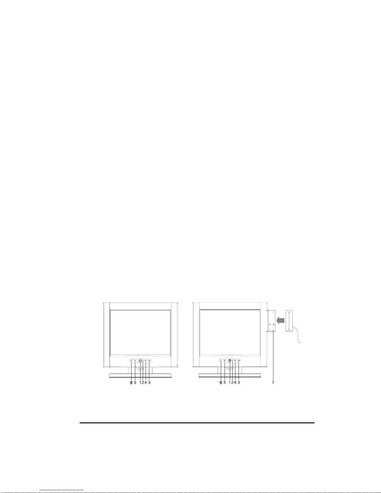
Taking a Look
Front View
1. Power Switch Pressing this button turns the display system power on or off.
2. Power LED This LED indicates different status when this unit operates in different
modes.
3
Page 4

3. Menu/Select ▲ Pressing this button pops up the OSD m enus on the screen, and used to
select (“Up” direction) the OSD control options on the screen.
4. Menu/Select ▼ Pressing this button pops up the OSD menus on the screen, and used to
select (“Down” direction) the OSD control options on the screen.
5. + This button is used to increase the value of the selected OSD control option.
6. − (1) This button is used to adjust the decreasing value of the selected OSD control
option. (2) used to select input sources (VGA or Video signal) when the OSD “main
menu” function is off (for model with video-in function only).
7. MSR (Magnetic Strip Reader) Holder (optional module)
Setting Up
WARNING When you disconnect the cord/cables, be sure to hold the connector instead
of the wire part.
Touch Screen Model:
Analog/Video-in Model:
1. Connect one end of the power adapter to the monitor and the other end to the connector
of the power cord. ()
2. Connect one end of the signal cable to the rear side of computer and the other to the LCD
monitor. Tighten by turning clockwise the two thum b screws to ensure proper grounding.
()
3. Connect one end of the touch (RS232) cable to the rear side of computer and the other to
the LCD monitor. Tighten by turning clockwise the two thumb screws to ensure proper
grounding. () (optional module)
4
Page 5

4. Connect either end of the audio cable to the audio in connector on the monitor and the
other end to the audio-out connector of your computer. () (optional module)
5. Connect either end of the video-in (S) cable to the connector on the monitor and the other
end to the video-out connector of your accessory. () (optional module)
6. Connect either end of the video-in (RCA) cable to the connector on the monitor and the
other end to the video-out connector of your accessory. () (optional module)
7. Pressing the power button on front panel turns the display system power on. ()
Display Angle
Tilting
For viewing clarity, you can tilt the monitor down to 5 degrees or up to 60 degrees.
CAUTION In order to protect the LCD, be sure to hold the base when
you adjust the LCD, and, do not touch the screen.
OSD Control Options
OSD Main Menu
VOLUME (optional module)
Adjust the speaker volume using + and
BRIGHTNESS
Adjust the brightness using + and
CONTRAST
Adjust the contrast using + and
SATURATION (for model with video-in function only)
Adjust the video image color saturation using + and - buttons.
HUE (for model with video-in function only)
Adjust the video image hue using + or - buttons.
OSD Main Menu (video-in function)
− buttons.
− buttons.
− buttons.
5
Page 6

COLOR
Adjust the values of color gain (RED, GREEN or BLUE) using + and
− buttons.
OSD Menu – Color
AUTOTUNE
Press + buttons to make LCD monitor adjust the related parameters automatically for
optimal display status.
QUALITY
FREQUENCY
OSD Menu - Quality
This item is used to decrease the vertical interference.
1. Select one display pattern from your computer.
2. Use + and − buttons on the LCD monitor to decrease th e vertical interference to get
the optimal display.
PHASE
This item is used to decrease the horizontal interference.
1. Select one display pattern from your computer.
2. Use + and − buttons on the LCD monitor to decrease the horizontal interference to
get the optimal display.
TRACK
Adjust the track using + and − buttons.
TEXT / GRP
Select “Text” or “Graphics” display in special mode.
POSITION
OSD Menu – Position
6
Page 7

HORIZONTAL
Pressing + moves the display image to the right; Pressing − moves the display image to the
left.
VERTICAL
Pressing + moves the display image upward; Pressing − moves the display image
downward.
CENTER
Pressing + or – buttons to automatically centers and sizes the screen image.
LANGUAGE
This item is used to select OSD languages: English, Chinese, and Japanese.
RECALL
Pressing + or – buttons to recall factory preset values.
SAVE EXIT
Pressing + or – buttons to save previous preset values.
Troubleshooting
The monitor does not respond after you turn on the system.
Check if the Power Switch of monitor is turned on.
Turn off the power and check the monitor’s power cord and signal cable for proper
connection.
The characters on the screen are dim.
Refer to the Controls and Adjustments section to adjust the brightness.
The screen is blank.
During operation, the monitor screen may automatically turn off as a result of Power
Saving feature. Press any key to see if the screen comes back.
Refer to the Controls and Adjustments section to adjust the brightness.
The screen flashes when it’s initialized.
Turn off the monitor and turn it on again.
7
Page 8

Display Modes
Item Resolution Type H. Scan V. Scan Pol.
(KHz) (Hz)
1 640X350 VGA 31.469 70.087 + / 2 640X350 VESA85 37. 861 85.080 + / 3 720X400 VGA 31.469 70.087 - / +
4 720X400 VESA85 37. 927 85.039 - / +
5 640X480 VGA 31.469 59.940 - / 6 640X480 VESA72 37. 861 72.809 - / 7 640X480 VESA75 37. 500 75.000 - / 8 640X480 VESA85 43. 269 85.008 - / -
9 800X600 SVGA 35.156 56.250 + / +
10 800X600 SVGA 37.879 60.317 + / +
11 800X600 VESA72 48.077 72.188 + / +
12 800X600 VESA75 46.875 75.000 + / +
13 800X600 SVGA 53.674 85.061 + / +
Specifications
Display
12.1” TFT Active Matrix Panel
Display Size
Pixel Pitch
Display Mode
Max. Resolution
Contrast Ratio
Brightness
246 (H) x 184.5 (V) mm
0.3075 (H) x 0.3075 (V) mm
VGA 640 x 350 (70 / 85Hz)
VGA 720 x 400 (70 / 85Hz)
VGA 640 x 480 (60 / 72 / 75 / 85Hz)
SVGA 800 x 600 (56 / 60 / 72 / 75 / 85Hz)
SVGA 800 x 600
150:1
2
200 Cd/m
8
Page 9

Response Time
50 ms
Viewing Angle
Display Color
Input Signal Video
Sync
Signal Connector
Front Control
OSD
Plug & Play
Audio System (option)
Touch Panel (option)
Video-in (option)
Power Adapter
MSR Holder (option)
90o (H) x 40o (V)
262K
R.G.B. Analog 0.7V
TTL Positive or Negative
15 Pin D-Sub
Power on / off with LED, Menu / Select (up, down),
Adjustment (+, -)
Volume, Brightness, Contrast, Color -RGB, AutoTune,
H-Position, V-Position, Center, Frequency, Phase, Track,
Text/Graphics, Language, Recall, Save, Saturation, Hue
DDC1 / 2B
1W / Per channel
Resistive / Capacitive Type with RS232 connector
S and RCA connectors
Input AC 100-240V, 50-60Hz, Output DC 12V/2.5A (min.)
Limited power source (LPS)
88(H) x 30(W) mm
peak to peak
Operating Conditions Temperature
Humidity
Altitude
Storage Conditions Temperature
Humidity
Dimensions (HxWxD)
Weight (Net)
Certifications
Specifications are subject to change without notice.
5oC ~ 35oC (41oF ~ 95oF)
20% ~ 80% (No Condensation)
To 10,000 Feet
o
C ~ 60oC (-4oF ~ 140oF)
-20
10% ~ 90% (No Condensation)
310 x 312 x 146mm
3.3Kg
C-UL, FCC, CE
WARNING Do not disassemble the monitor. Contact your dealer if needed.
9
 Loading...