

GVI Security GV-SCS530 User Manual
GVI Security
2801 Trade Center Dr., Suite 120 • Carrollton, TX 75007 • Toll Free: 888-595-2288 • www.gviss.com
GV-SCS530 Users Manual
INTEGRATED PTZ POSITIONING
SYSTEM, 36X OPTICAL ZOOM, WDR,
D/N, INDOOR OUTDOOR CAMERA
before installing and using the camera, please read these instructions
thoroughly and retain them for later reference.

SUMMARY
The “Smart Camera System” GV-SCS530 is a high-performance, integrated positioning system featuring a 530TV Lines resolution, 36x optical zoom camera, lens and complete PTZ unit.
Made from die-cast aluminum construction, with an IP66 rated weather-resistant design. The
GV-SCS530 has a built-in heater, wiper, window defroster, sun-shield, anti-fogging, dust-proof
and frost protection function. It can withstand high winds, offers complete 360-degree panning
with tilt ranges of +33 degrees and -83 degrees from the horizontal. What’s more, the camera is
equipped with a number of convenient functions such as Spherical Privacy Zone Masking with
Mosaic Effect, Video Motion Detection, Multi-Line On-Screen Display, E-ip, and Picture Freeze.
The GV-SCS530 is also compatible with many popular control protocols.
FEATURES
• 1/4 Inch type ExView HAD CCD
• 530TV Lines Resolution
• Minimum Scene Illumination: 1.4 lux @ 1/60s shutter speed, 0.1 lux @ 1/4s shutter speed
• 36x Optical Zoom (12x Digital zoom, 432x total)
• True Day/Night with IR Filter Removal
• Wide Dynamic Range
• E-ip
• Picture Freeze
• Advanced Spherical Privacy Zone Masking Function with Mosaic Effect
• Video Motion Detection
• Multi Line On-Screen Display
• Electronic shutter / slow shutter
• Internal / External synch (V-lock)
• Die-cast Aluminum construction, high temperature resistant
• Weather resistant, dust proof design, protection grade IP66
• 360° continuous panning
• Tilt range +33°~-80°
• Auto pan function between 2 presets
• 128 presets 6 tracks
• Anti fogging and frost protection function
• Wiper
• Factory presets
• Register set command
• RoHS-compliant
• Multi Protocol Control
• Included Wall Mount
NoTES
I. NOTES FOR ATTENTION
1. Read the manual carefully before installing the product.
2. Power Supply: 220V/110V/24V, refer to the sticker on the product.
3. Avoid incorrect shipping methods such as overstacking or strong vibration during the course
of transportation, storage and installation, as the product could be damaged.
4. Do not dismount components inside the product to avoid occurrence of trouble. There are no
user serviceable parts inside the camera.
5. Observe all electric safety standard in use and installation and use power supply attached
to the product. RS-485 and video signal should keep enough distance with the high voltage
devices and cable during the course of transmission, and take protection measures such as
anti-lightning and surging if necessary.
6. Do not use the product under conditions which exceeds the temperature, humidity or specications of power supply.
7. Do not aim the camera at the sun or very bright object or to monitor bright and still object,
whether the power supply is switched on or off.
8. Do not clean the product with strong or abrasive detergent. Clean out dirt with dry cloth or mild
detergent if dirt is not easily removed.
9. Take care to set up the product to avoid collision or vibration. Improper application can cause
damage.
10. Install the product in a location that is capable of supporting the Camera PTZ system weight.
11. Wipe dust on the lens with special lens paper.
WARNING:
The exclamation point within an equilateral triangle is intended to alert the user to
the presence of important operating and maintenance (servicing) instructions in the
literature accompanying the product.
This symbol is intended to alert the user to the presence of uninsulated “dangerous
voltage” within the product’s enclosure that may be of sufcient magnitude to consti-
tute a risk of electric shock to persons.
RISK OF ELE CTRI C SH OCK
DO NOT OPE N
CAUT ION: TO REDUCE THE RISK OF ELECTR IC SHOCK
DO NOT REMOVE COVER OR BACK. NO
USER SERVICEABLE PAR TS INS IDE
REFER SERVICING TO QUALIF IED SERVICE
PERSONNEL
CAUTION:
To prevent electric shocks and
risk of re hazards do NOT use
other than specied power
source.
1 2 3 4 5 6
DIP
ON
1 2 3 4 5 6 7 8 9 10
DIP
ON
1 2 3 4 5 6
DIP
ON
1 2 3 4 5 6 7 8 9 10
DIP
ON
1 2 3 4 5 6
DIP
ON
1 2 3 4 5 6 7 8 9 10
DIP
ON
II. INTRODUCTION OF FUNCTIONS
1. Unlimited rotation 360° horizontally and from +33° to -80° vertically.
2. The horizontal speed is 0 - 40°/sec while the vertical speed is 0 - 20°/sec (wind speed less
than 50 miles/hour).
3. At the preset position, the horizontal speed is 0 - 100°/sec while the vertical speed is 0 - 40°/
sec (wind speed less than 50 miles/hour).
4. Automatic control of constant temperature, manual rain wiper/defroster control.
5. IP grade IP66.
6. The bearable maximum wind speed is 130 miles/hour.
7. 128 preset positions in memory and 6 groups of programmable patrol loci, as well as linear
scan between two points with adjustable speed and variable direction,
8. 16 common protocols integrated, four kinds of baud rate 2400/4800/9600/19200 bps available
and 1024 addresses are supported (0 - 1023).
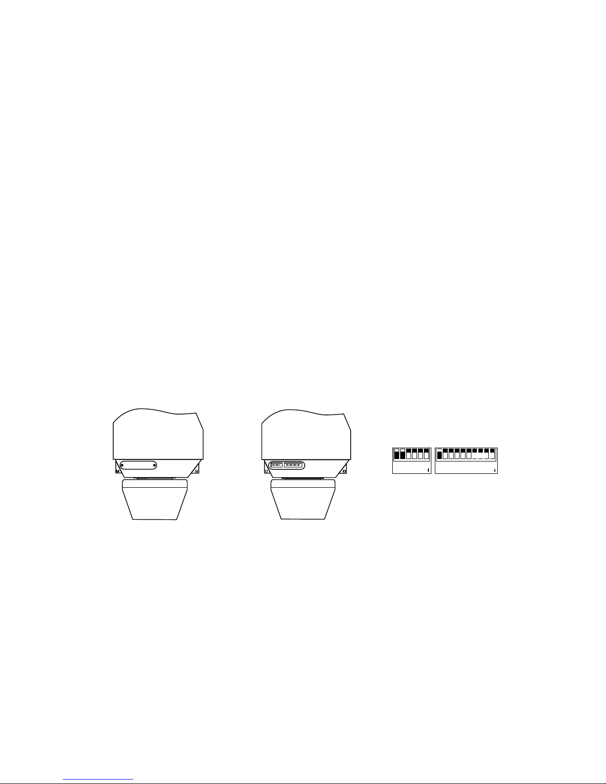
III. QUICK GUIDE OF INSTALLATION
1. Modify the Protocol and the Address (jump over this section if no modication)
Remove the small metal cover on the bottom shown as dotted-lined part on Figure 3.1.1 to
expose DIP switch of the address and the protocol shown as Figure 3.1.2. The detailed drawing is shown as in Figure 3.1.1.
Shown as Figure 3.1.3, the 10-bit DIP stands for the addresses which can be from 0 to 1023.
The 6-bit DIP stands for the protocols in which bits 1-4 mean the protocol while bits 5-6 means
the baud rate. Push the DIP downward means ON otherwise it means OFF. For example
the address in the gure means 1 while the protocol means PELCO-D with the baud rate of
2400bps which can be found from the table.
The top line and the bottom line display prompt message, and the middle area displays infor-
mation of each locus, one line shows data of two points. Move the cursor by PAN LEFT/RIGHT
and modify data by TILT UP/DOWN. Press the button down for 1 second to accelerate. Press
CLOSE button to exit the edit state and store modication. In above gure, the program stores
four patrol points. The settable range of POS is from 1 to 63 or 65 to 128. In case POS is “---“,
it means the skip this point. The settable range of SP is from 0 to 8 (0 and 1 are same at the
highest speed while grade 8 has the lowest speed). The settable rage of TM is from 0 to 99
seconds.
Operation of the Title of Preset under Edit State
After entering into the edit state, the screen show as
the drawing. You can nd current setup is the preset 1
with the title “NO TITLE”. Move the cursor by PAN LEFT/
RIGHT and modify data by TILT UP/DOWN. Press the
button down for 1 second to accelerate. Press CLOSE
button to exit the edit state and save modication. The
title of preset can contain 8 characters such as 0~9, A~Z,
+, - and blank. Note: the rst letter should be 0~9 or A~Z
otherwise it means to delete the title of the presets and it
shall only show “NO.XXX” without the title when preset
points.
V. SPECIAL OPERATION
The preset 51 to 60 are used for special functions. It has special meanings to set or call these
points. Therefore these points should not be used in functions of automatic operation of the
pan/tilt such as multiple points patrol, external alarm linkage etc. so as to avoid error actions.
Preset Set Preset Call Preset
51 Wiper ON Wiper OFF
52 Defroster ON Defroster OFF
53 Auxiliary Output AC24V ON Auxiliary Output AC24V OFF
54 Linkage of External Alarm 1 ON Linkage of External Alarm 1 OFF
55 Linkage of External Alarm 2 ON Linkage of External Alarm 2 OFF
56 Reserved Reserved
57 Reserved Reserved
58 Reserved Reserved
59 Reserved Reserved
60 Reserved Reserved
Figure 3.1.1 Figure 3.1.1 Figure 3.1.3
2 11

Table 1 Table of Addresses in DIP Switch
Address
of PT
Status of DIP Switch
DIP-1 DIP-2 DIP-3 DIP-4 DIP-5 DIP-6 DIP-7 DIP-8 DIP-9 DIP-10
1 ON OFF OFF OFF OFF OFF OFF OFF OFF OFF
2 OFF ON OFF OFF OFF OFF OFF OFF OFF OFF
3 ON ON OFF OFF OFF OFF OFF OFF OFF OFF
4 OFF OFF ON OFF OFF OFF OFF OFF OFF OFF
5 ON OFF ON OFF OFF OFF OFF OFF OFF OFF
6 OFF ON ON OFF OFF OFF OFF OFF OFF OFF
7 ON ON ON OFF OFF OFF OFF OFF OFF OFF
8 OFF OFF OFF ON OFF OFF OFF OFF OFF OFF
9 ON OFF OFF ON OFF OFF OFF OFF OFF OFF
10 OFF ON OFF ON OFF OFF OFF OFF OFF OFF
11 ON ON OFF ON OFF OFF OFF OFF OFF OFF
12 OFF OFF ON ON OFF OFF OFF OFF OFF OFF
13 ON
OFF ON ON OFF OFF OFF OFF OFF OFF
14 OFF ON ON ON OFF OFF OFF OFF OFF OFF
15 ON ON ON ON OFF OFF OFF OFF OFF OFF
16 OFF OFF OFF OFF ON OFF OFF OFF OFF OFF
17 ON OFF OFF OFF ON OFF OFF OFF OFF OFF
18 OFF ON OFF OFF ON OFF OFF OFF OFF OFF
... ... ... ... ... ... ... ... ... ... ...
1023 ON ON ON ON ON ON ON ON ON ON
Examples
 Loading...