

GVI Security GV-NC-201VO User Manual
WWW.GVISS.COM
GV-NC-201VO
H.264 Megapixel Anti-vandal Network Camera
USER MANUAL

GVI Security • Toll Free: 888-595-2288 • Fax: 972-245-7333
This product specifications and manual are also available in pdf format at www.gviss.com
The information is subject to change without notice • v4.28.10
2
Table of Contents
1. Overview ................................................................................................................... 3
1.1 Features .........................................................................................................................................................3
1.2 Package Contents .......................................................................................................................................4
2. Introduction of IP Dome Camera ........................................................................5
2.1 Camera Dimensions ...................................................................................................................................5
2.2 Camera’s Connectors ................................................................................................................................6
3. System Requirements ............................................................................................. 7
4. Installation ................................................................................................................. 8
4.1 Power and Ethernet Cable Connection ................................................................................................8
4.2 Hard Ceiling .................................................................................................................................................9
4.3 4S Mount Electrical Box ............................................................................................................................14
5. Accessing Camera ................................................................................................... 17
6. Conguration & Operation ................................................................................... 22
6.1 Browser-based Viewer Introduction .......................................................................................................22
6.2 Home Page ...................................................................................................................................................23
6.3 System Related Settings ............................................................................................................................24
6.3.1 Host Name and System Time Setting .....................................................................................................25
6.3.2 Security .........................................................................................................................................................26
6.3.3 Network .......................................................................................................................................................28
6.3.4 DDNS ............................................................................................................................................................31
6.3.5 Mail .................................................................................................................................................................32
6.3.6 FTP .................................................................................................................................................................33
6.3.7 Application (Excluding Compact IP Dome) ..........................................................................................33
6.3.8 Motion Detection .......................................................................................................................................37
6.3.9 Snapshot ........................................................................................................................................................39
6.3.10 View Log File ................................................................................................................................................40
6.3.11 View User Information ..............................................................................................................................41
6.3.12 View Parameters .........................................................................................................................................43
6.3.13 Factory Default ...........................................................................................................................................43
6.3.14 Software Version .........................................................................................................................................44
6.3.15 Software Upgrade .......................................................................................................................................45
6.4 Video and Audio Streaming Settings .......................................................................................................47
6.4.1 Video Resolution and Rotate Type ..........................................................................................................48
6.4.2 Video Compression....................................................................................................................................50
6.4.3 Video OCX Protocol .................................................................................................................................51
6.4.4 Video Frame Skip ........................................................................................................................................52
6.4.5 Audio Mode and Bit Rate Settings ..........................................................................................................53
6.5 Camera Settings ..........................................................................................................................................54
6.5.1 Exposure Setting .........................................................................................................................................55
6.5.2 White Balance Setting ................................................................................................................................56
6.5.3 Backlight Setting ..........................................................................................................................................56
6.5.4 Brightness Setting .......................................................................................................................................57
6.5.5 Sharpness Setting ........................................................................................................................................57
6.5.6 Contrast Setting ..........................................................................................................................................57
6.5.7 Digital Zoom Setting ..................................................................................................................................57
6.5.8 WDR Function ............................................................................................................................................57
6.5.9 3DNR Function ...........................................................................................................................................58
6.5.10 TV System Setup .........................................................................................................................................58
6.6 Logout ...........................................................................................................................................................58
Appendix A: Technical Specications .................................................................................... 59
Appendix B: Internet Security Settings ................................................................................ 60
Appendix C: DC Viewer Download Procedure ................................................................ 63

GVI Security • Toll Free: 888-595-2288 • Fax: 972-245-7333
This product specifications and manual are also available in pdf format at www.gviss.com
The information is subject to change without notice • v4.28.10
3
1. Overview
The autoIP™ GV-NC-201VO network camera provides high quality, 1.3 megapixel
resolution video in the most demanding light conditions. High video quality is
achieved by coupling a 1/3” Ex-View-HAD CCD progressive scan image sensor
with an IR cut lter and Wide Dynamic Range capability. H.264 compression retains
the high video quality at a low data rate. The anti-vandal housing with IP66 rating
provides a rugged package for both indoor and outdoor applications. Power over
Ethernet (PoE) reduces installation time and costs. The camera is compatible with
the userfriendly autoIP™ open platform video management software for quick plug
and play installation.
1.1 Features
• Resolution: 1.3MP (1280x960)
• 1/3” Ex-View-HAD Progressive Scan CCD
• F1.4 / f=3.3 – 12 mm Varifocal Lens
• Multiple Codec (H.264, MPEG-4, MJPEG)
• Simultaneous Dual Codec Support
• Wide Dynamic Range
• True Day/Night with IR Cut Filter
• 3D Noise Reduction
• Audio
• Privacy Masks
• Flip, Mirror, Rotate Functions
• 3 Axis Installation
• Micro SD Card Support
• Analog Output
• IP66 Rated
• PoE / DC12V / AC24V
GVI Security • Toll Free: 888-595-2288 • Fax: 972-245-7333
This product specifications and manual are also available in pdf format at www.gviss.com
The information is subject to change without notice • v4.28.10
4
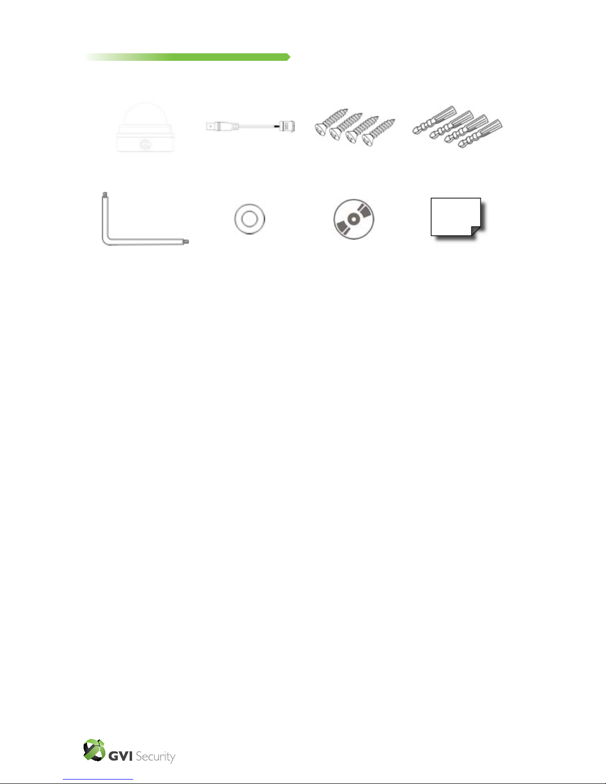
1.2 Package Contents
Please check the package contains the following items listed below.
HD WDR Vandal Proof IP
Dome Camera
Security Torx
Power Cable
Rubber Washers (×6)
Self Tapping Screws
(×4)
CD
(bundled software
and documentation)
Plastic Screw Anchors
(×4)
Quickstart Guide

GVI Security • Toll Free: 888-595-2288 • Fax: 972-245-7333
This product specifications and manual are also available in pdf format at www.gviss.com
The information is subject to change without notice • v4.28.10
5
2. Introduction of IP Camera
This chapter will provide the camera dimensions for reference before installation.
Denition of each connector on the camera’s PCB board will also be specied.
2.1 Camera Dimensions
The IP Dome Camera’s dimensions are shown below.
28.15”
Top View Side View
51.39”
29.72”
GVI Security • Toll Free: 888-595-2288 • Fax: 972-245-7333
This product specifications and manual are also available in pdf format at www.gviss.com
The information is subject to change without notice • v4.28.10
6
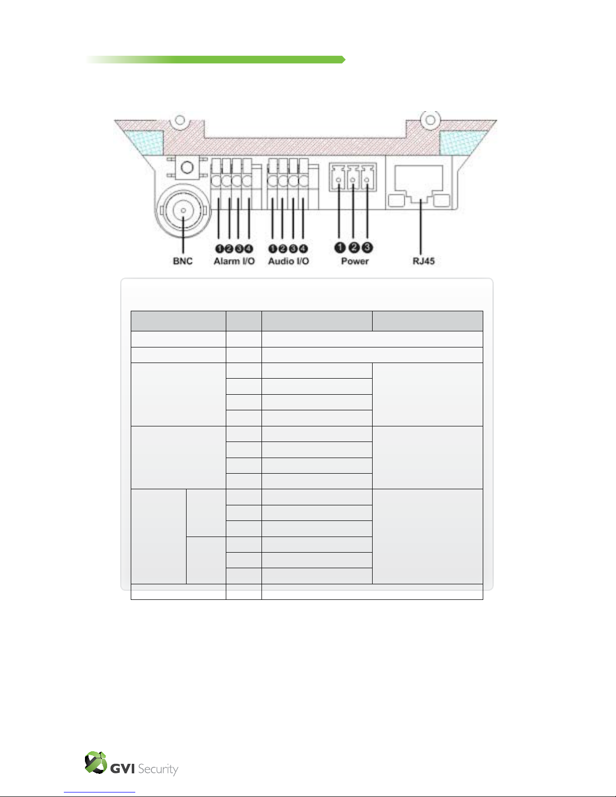
2.2 Camera’s Connectors
The diagram below shows the IP Dome Camera’s reset button and various
connectors. Denition for each connector will be given as follows.
Connector Pin No. Definition Remarks
Reset Button - Restore to factory defualt
BNC - Analog Video Output
Alarm I/O
1 Output+
Alarm Connection
2 Output-
3 Input+
4 Input-
Audio I/O
1 Input
Two-way audio transmission
2 GND
3 Output (R)
4 Out (L)
Power
DC 12V
1 Power
Power Connection
2 Reserved
3 GND
AC 24V
1 Power-1
2 Earth GND
3 Power-2
RJ45 - 10/100 Ehternet / PoE

GVI Security • Toll Free: 888-595-2288 • Fax: 972-245-7333
This product specifications and manual are also available in pdf format at www.gviss.com
The information is subject to change without notice • v4.28.10
7
3. System Requirements
To perform the IP Camera via web browser, please ensure your PC has a good
network connection, and meets system requirements as described below.
Items System Requirement
Personal Computer 1. Intel
®
Pentium® M, 2.16 GHz or Intel® CoreTM2 Duo, 2.0
GHz
2. 2 GB RAM or more
Operating System Windows VISTA or Windows XP
Web Browser Microsoft Internet Explorer 6.0 or later
Network Card 10Base-T (10 Mbps) or 100Base-TX (100 Mbps) operation
Viewer ActiveX control plug-in for Microsoft IE

GVI Security • Toll Free: 888-595-2288 • Fax: 972-245-7333
This product specifications and manual are also available in pdf format at www.gviss.com
The information is subject to change without notice • v4.28.10
8
4 Installation
Please read the instructions provided in this chapter thoroughly before installing the
Anti-Vandal Network Camera.
4.1 Power and Ehternet Cable Connection
Power Connection
Make sure the camera’s power cable is correctly and rmly connected; refer to
the pin denition table in section 2.2 Camera’s Connectors. If using Power over
Ethernet (PoE), make sure Power Sourcing Equipment (PSE) is in use in the network.
Ethernet Cable Connection
Use of Category 5 Ethernet cable is recommended for network connection; to have
best transmission quality, cable length shall not exceed 100 meters. Connect one
end of the Ethernet cable to the RJ-45 connector of the IP Dome Camera, and the
other end of the cable to the network switch or PC.
Check the status of the link indicator and activity indicator LEDs; if the LEDs are
unlit, please check LAN connection.
Green Link Light indicates good network connection.
Orange Activity Light ashes for network activity indication.
NOTE: In some cases, you may need to use an Ethernet crossover cable
when connecting the IP Dome Camera directly to the PC.
GVI Security • Toll Free: 888-595-2288 • Fax: 972-245-7333
This product specifications and manual are also available in pdf format at www.gviss.com
The information is subject to change without notice • v4.28.10
9
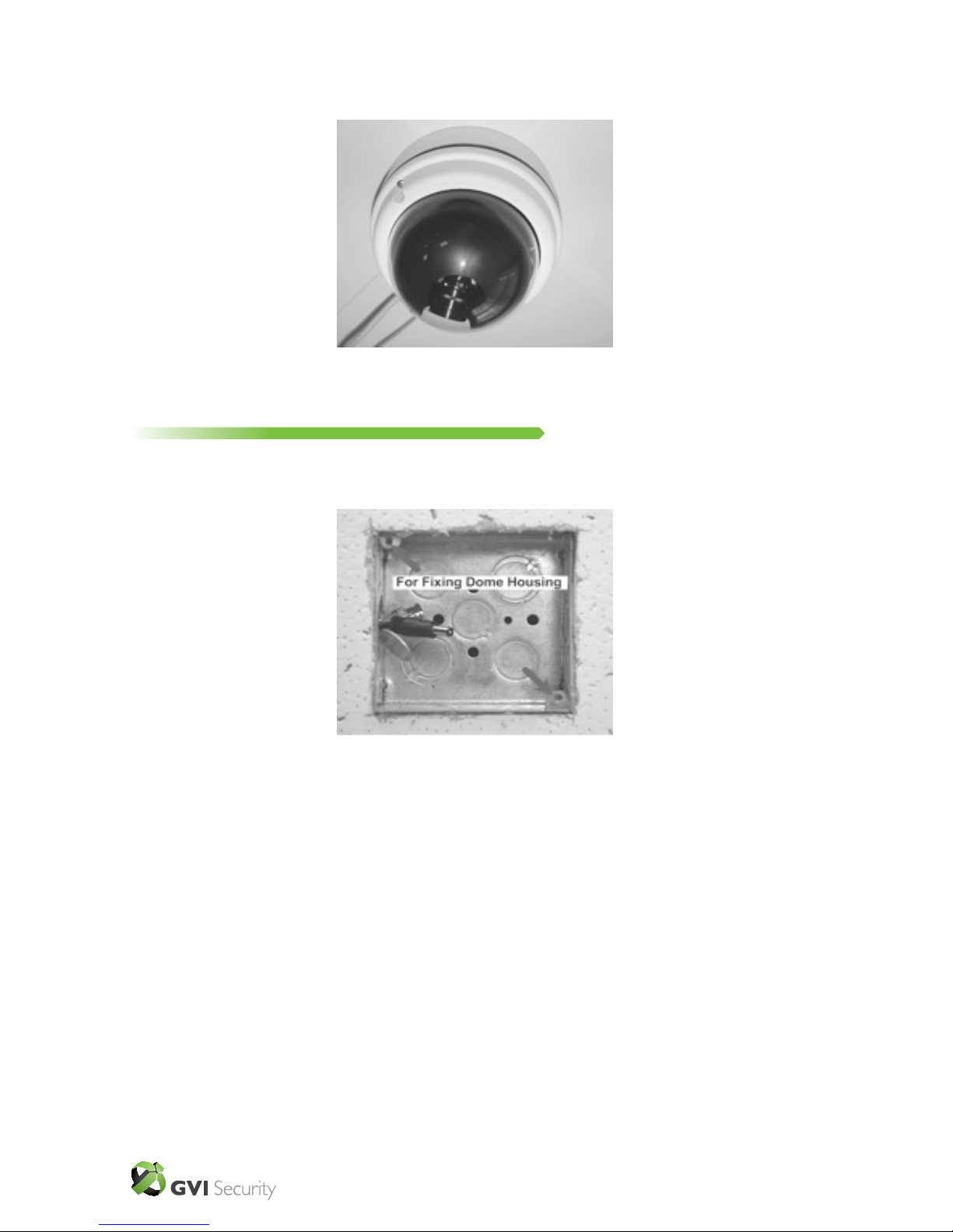
4.2 Hard Ceiling
The Vandal Proof IP Dome Camera can be installed directly on a wall or ceiling.
Please note that the wall or ceiling must have enough strength to support the
camera.
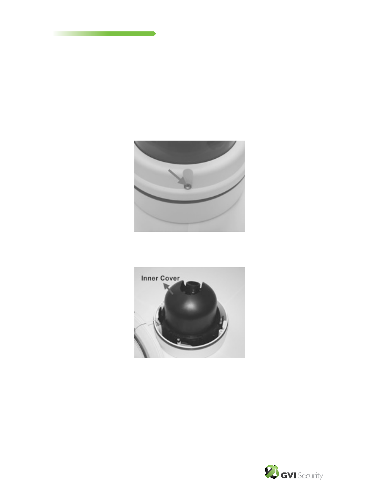
Follow the steps below to install the IP Dome Camera:
Step 1: Unpack the Anti-vandal Network Dome Camera.
Step 2: Use the supplied Security Torx to unscrew the two screws on the side of
the dome camera cover, as shown in the gure, and open the dome camera cover.
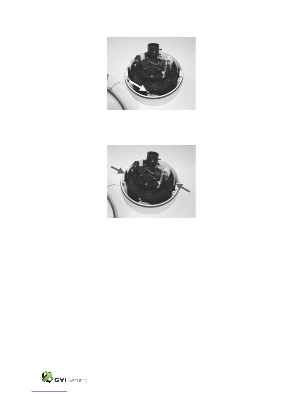
Step 3: Press both sides of the inner cover and remove it from the camera unit.
GVI Security • Toll Free: 888-595-2288 • Fax: 972-245-7333
This product specifications and manual are also available in pdf format at www.gviss.com
The information is subject to change without notice • v4.28.10
10
Step 4: Unscrew the module-fastened Torx screw, as shown in the gure, with the
supplied Security Torx.
Step 5: Press on the sides of the snap-on module, as indicated in the gure, and
detach it from the Dome Camera’s housing.
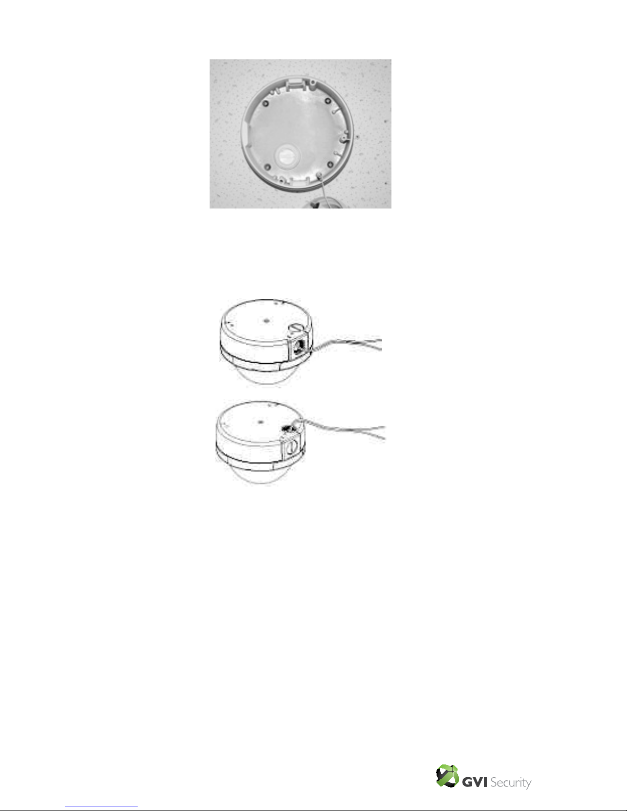
Step 6: Mark the positions of the four screw holes on the base of the Dome
Camera at the chosen installation location.
Step 7: In the marked locations, drill each hole slightly smaller than the supplied
screw anchors.
Step 8: Put supplied anchors into these drilled holes.
GVI Security • Toll Free: 888-595-2288 • Fax: 972-245-7333
This product specifications and manual are also available in pdf format at www.gviss.com
The information is subject to change without notice • v4.28.10
11
Step 9: Fasten the camera’s housing with the four equipped self tapping screws.
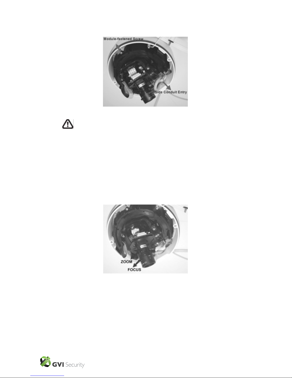
Step 10: Thread the power and Ethernet cables through either the side conduit
entry or back conduit entry, as illustrated. Users may use a coin to screw off the
conduit entry block.
Connect the Cable(s) to the Unit
Connect the power and Ethernet connectors (on the Dome Camera unit) with
their cables, respectively.
GVI Security • Toll Free: 888-595-2288 • Fax: 972-245-7333
This product specifications and manual are also available in pdf format at www.gviss.com
The information is subject to change without notice • v4.28.10
12
Step 11: Attach the snap-on module into the Dome Camera housing, and screw the
module-fastened screw tightly with the Security Torx to secure the camera module.
Step 12: Connect the power and network outputs.
Step 13: Access the camera browser-viewer for viewing images. Please refer to
“Chapter 5. Accessing Camera” for further details. Users may also prefer using the
camera’s BNC connector for video output.
Step 14: Adjust the camera’s zoom level and focal length via zoom and focus ring
screws.
Adjust the zoom ring screw to set the desired zoom; subsequently, modifying the
focus ring screw to set the desired focal length.
NOTE: The terminal blocks should face the side conduit entry, as shown in
the gure.
GVI Security • Toll Free: 888-595-2288 • Fax: 972-245-7333
This product specifications and manual are also available in pdf format at www.gviss.com
The information is subject to change without notice • v4.28.10
13
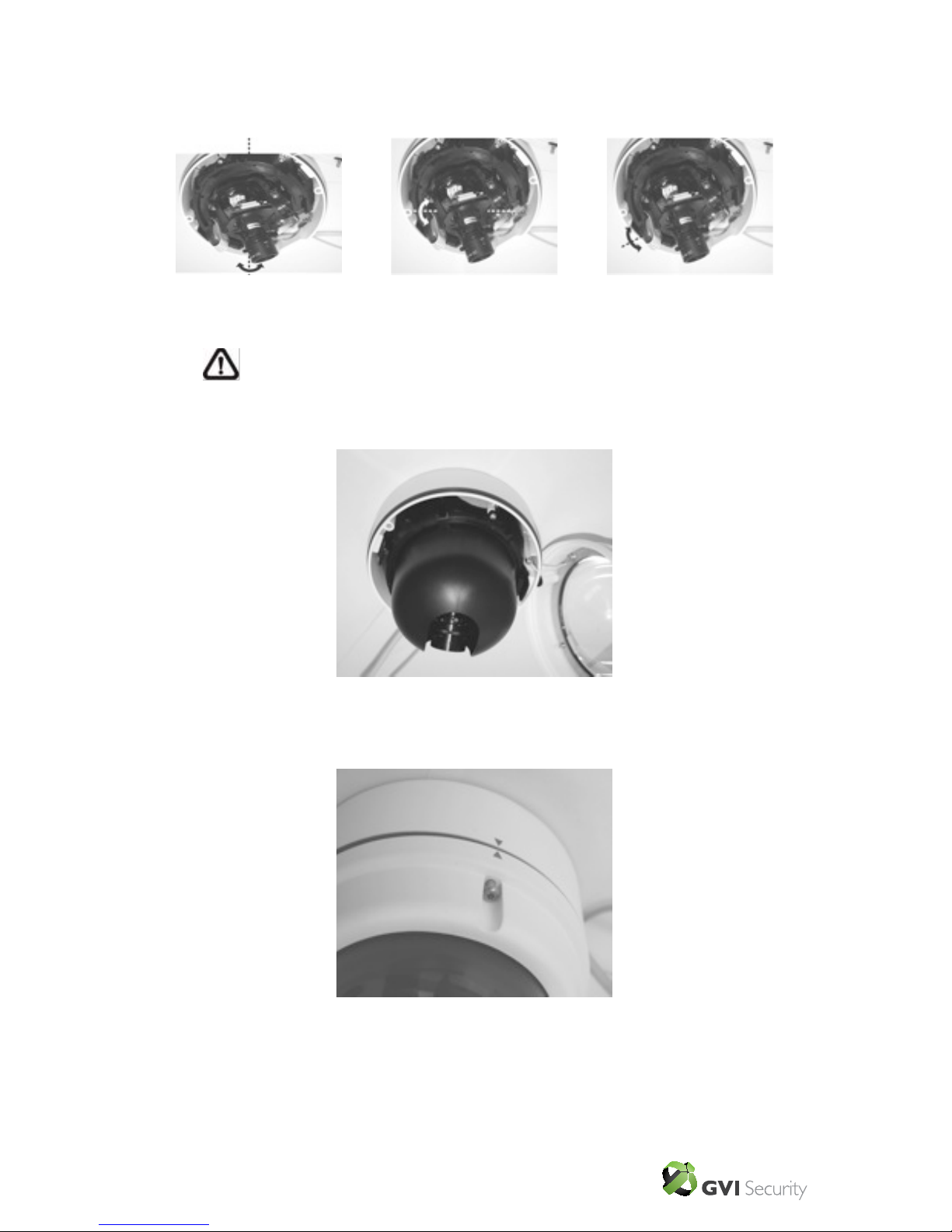
Step 15: Adjust the camera to a desired angle, as shown below. Pan adjustment
range is close to 360°; and rotation angle range approaches to 270°. Tilt is adjustable
between -10° ~ 90°.
Step 16: Put the inner cover back to the camera unit.
Step 17: Place the camera cover back, aligning the arrow mark on the dome cover
with the one on the housing as shown in the gure.
NOTE: Adjust the lens carefully within the limits mentioned above, or the
cables underneath would be harmed.
Pan Adjustment
Rotation Adjustment
Tilt Adjustment
GVI Security • Toll Free: 888-595-2288 • Fax: 972-245-7333
This product specifications and manual are also available in pdf format at www.gviss.com
The information is subject to change without notice • v4.28.10
14
Step 18: Fasten two screws on the sides of the dome cover. Camera installation is
complete.
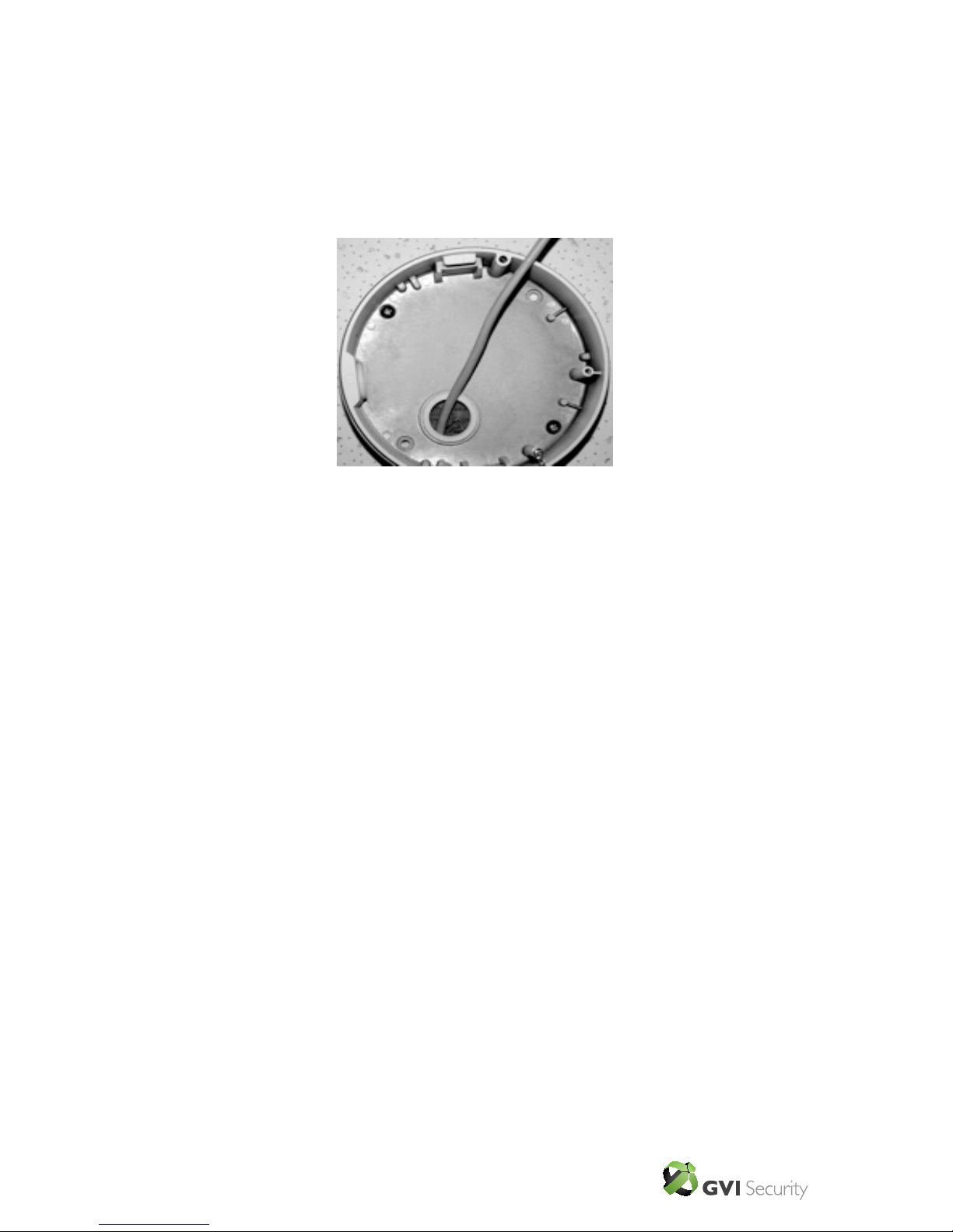
4.3 4S Mount Electrical Box
Before installing the IP Dome Camera in the 4S Electrical Box, please unscrew and
open the dome cover with the Security Torx.
Step 1: Run the wires (Ethernet and power) through the wall.
Step 2: Disassemble the camera’s inner cover (see the illustration in 4.2 Hard
Ceiling: Step 3) from the Dome Camera unit.
GVI Security • Toll Free: 888-595-2288 • Fax: 972-245-7333
This product specifications and manual are also available in pdf format at www.gviss.com
The information is subject to change without notice • v4.28.10
15
Step 3: Detach the snap-on camera module from the camera housing by unscrewing
the module. Then press the sides of camera module and pull it slightly out of the
housing.
Step 4: Thread the power and Ethernet cables through either the side conduit entry
or back conduit entry. Then fasten the dome camera’s housing on the Electrical Box
with the two screws.
Step 5: Connect the power and Ethernet cables to their connectors on the Camera
unit.
Step 6: Attach the snap-on camera module into the Dome Camera’s housing. Screw
on the Torx screw to secure the camera module.
Step 7: Access the camera browser-viewer for viewing images. Please refer to
“Chapter 5. Accessing Camera” for further details. Users can also use the camera’s
BNC connector for video output.
Step 8: Adjust the camera’s zoom level and focal length via zoom and focus ring
screws.
Step 9: Position the camera at a desired angle through PTZ adjustment.

GVI Security • Toll Free: 888-595-2288 • Fax: 972-245-7333
This product specifications and manual are also available in pdf format at www.gviss.com
The information is subject to change without notice • v4.28.10
16
Step 10: Place the cover back, aligning the arrow mark on the dome cover with the
one on the housing.
Step 11: Screw on the two Torx screws on the side of the dome cover tightly to
fasten the dome cover. Camera installation is complete.
GVI Security • Toll Free: 888-595-2288 • Fax: 972-245-7333
This product specifications and manual are also available in pdf format at www.gviss.com
The information is subject to change without notice • v4.28.10
17
5 Accessing Camera
autoIP™ Discovery Tool can be used to discover the cameras in the network.
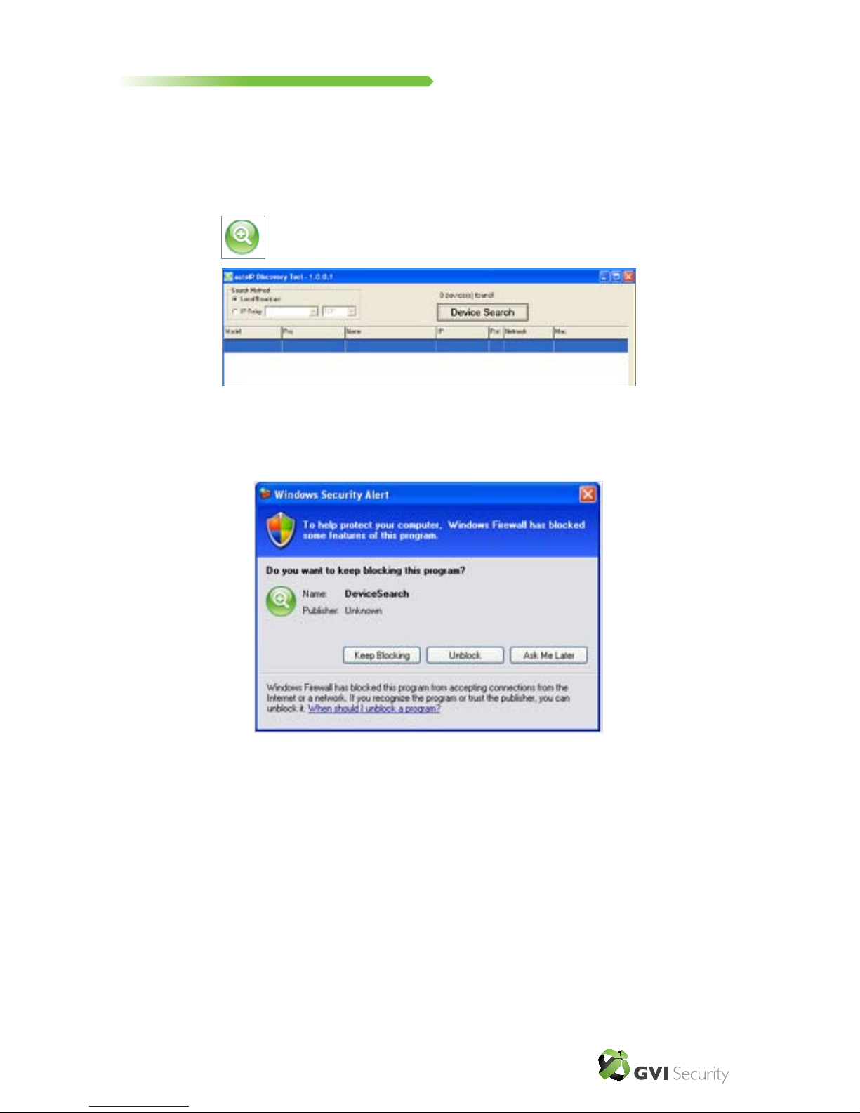
autoIP™ Discovery Tool
Step 1: Double click on the autoIP™ Discovery Tool.exe (see the icon below);
its window will appear as shown below. Then click the “Device Search” button.
Step 2: The security alert window will pop up. Click “Unblock” to continue.
GVI Security • Toll Free: 888-595-2288 • Fax: 972-245-7333
This product specifications and manual are also available in pdf format at www.gviss.com
The information is subject to change without notice • v4.28.10
18
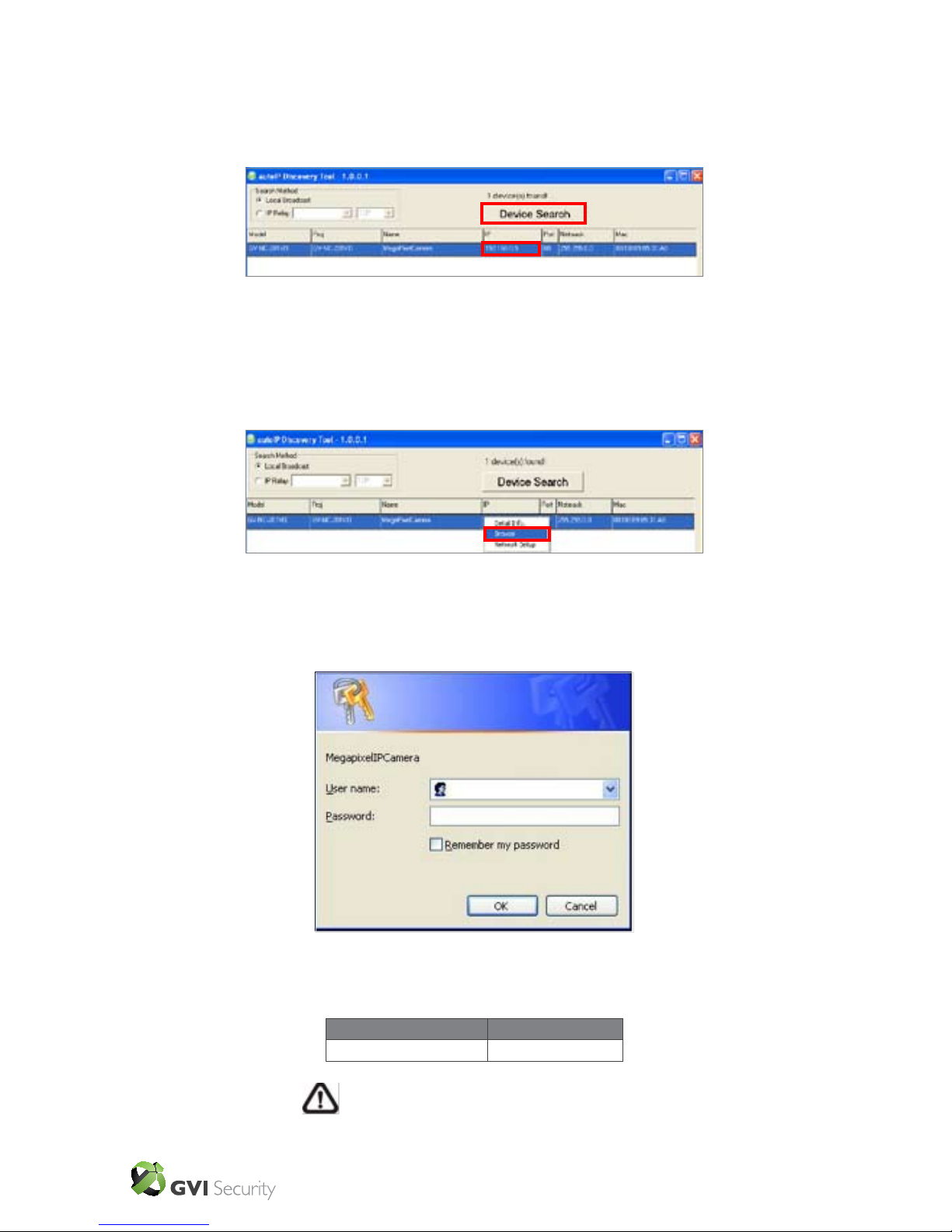
Device Search
Step 3: Click “Device Search” again, and all the discovered IP devices will be listed
in the page, as shown in the gure below. The IP Camera’s default IP address is:
192.168.0.250. (If xed IP address is selected.)
Step 4: Double click or right click and select “Browse” to access the camera
directly via web browser.
Step 5: Then the prompt window of request for entering default username and
password (as shown below) will appear for log in to the IP Camera.
The default login ID and password for the Administrator are:
Login ID Password
Admin 1234
NOTE: ID and password are case sensitive.
GVI Security • Toll Free: 888-595-2288 • Fax: 972-245-7333
This product specifications and manual are also available in pdf format at www.gviss.com
The information is subject to change without notice • v4.28.10
19
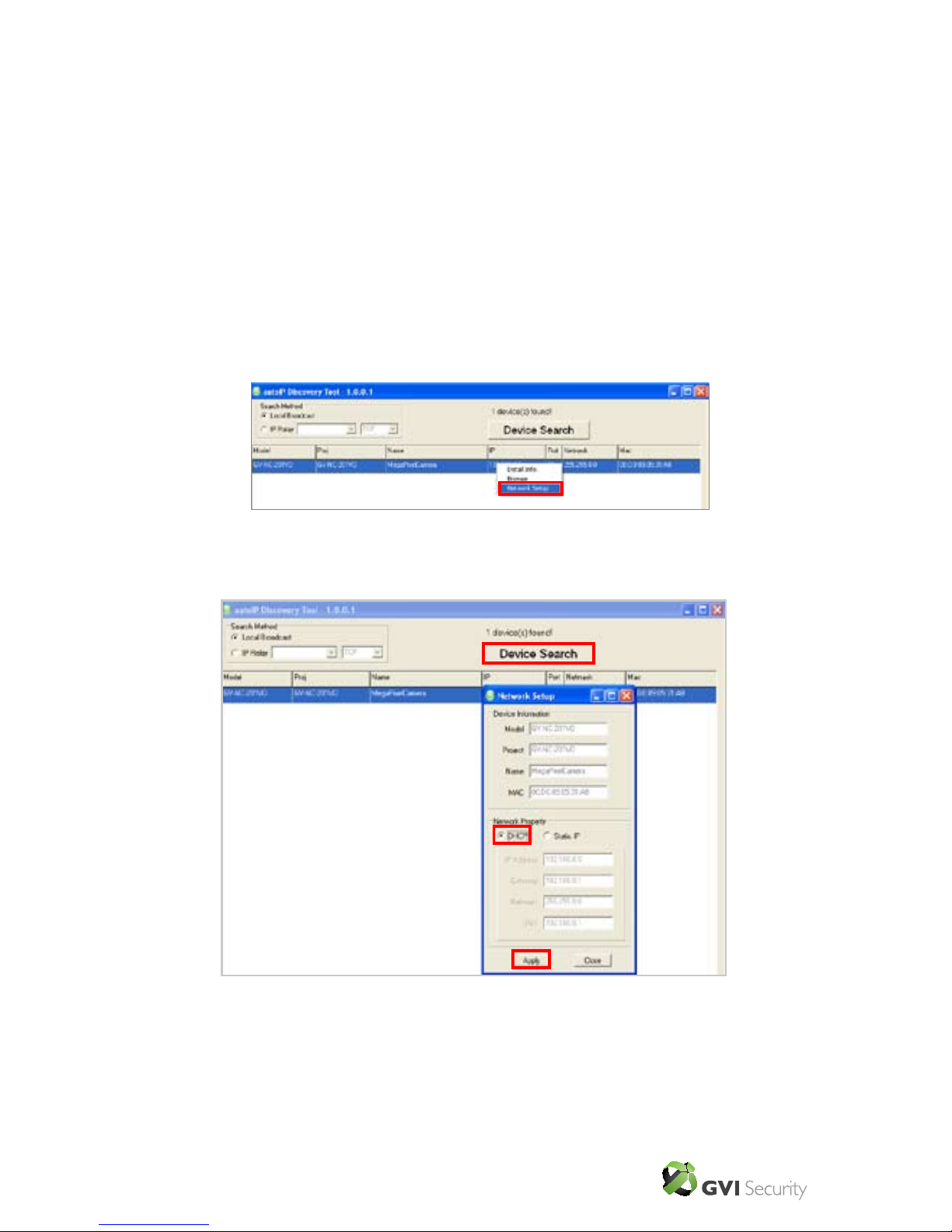
Additionally, users can change the IP Camera’s network property, either DHCP or
Static IP directly in the device list. Refer to the following section for changing the IP
Camera’s network properties.
Example of Changing IP Camera’s Network Properties
Users can change an IP Camera’s network properties, ex. from static IP to DHCP, in
the device list. The way to change the IP Camera’s network properties is specied
below:
Step 1: In the device list, click on the IP Camera that you would like to modify. On
the selected item, right click and select “Network Setup.” Meanwhile, record the IP
Camera’s MAC address, for future identication.
Step 2: The “Network Setup” page will come out. Select “DHCP,” and press
“Apply” button down the page.

GVI Security • Toll Free: 888-595-2288 • Fax: 972-245-7333
This product specifications and manual are also available in pdf format at www.gviss.com
The information is subject to change without notice • v4.28.10
20
Step 3: Click “OK”. Wait for one minute to rediscover the IP Camera.
Step 4: Click the “Device Search” button to rediscover all the devices. Then select
the IP Camera with the matching MAC address. Double click on the IP Camera, and
the login window will come out.
Step 5: Enter User name and Password to access the IP Camera
GVI Security • Toll Free: 888-595-2288 • Fax: 972-245-7333
This product specifications and manual are also available in pdf format at www.gviss.com
The information is subject to change without notice • v4.28.10
21
Installing DC Viewer Software Online
For the initial access to the IP Camera, a client program, DC Viewer, will be
automatically installed to your PC when connecting to the IP Camera.
If the Web browser doesn’t allow DC Viewer installation, please check the Internet
security settings or ActiveX controls and plug-ins settings (see Appendix B: Internet
Security Settings) to continue the process.
The Information Bar (just below the URL bar) may come out and ask for permission
to install the ActiveX Control for displaying video in browser. Right click on the
Information Bar and select “Install ActiveX Control…” to initiate the installation.
Then the security warning window will pop up. Click “Install” to continue with
software installation.
Click “Finish” to close the DC Viewer window when download is nished. For the
detailed software download procedure, please refer to Appendix C: DC Viewer
Download Procedure.
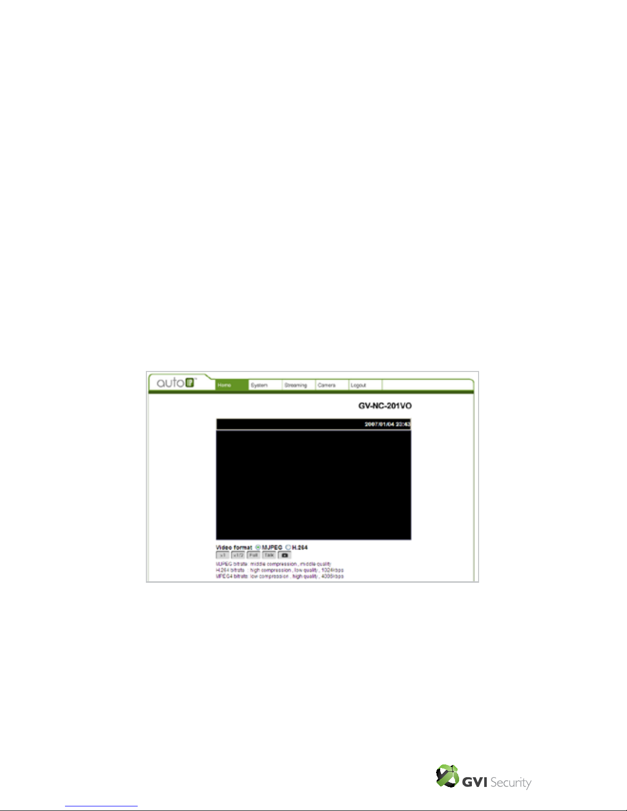
After the log-in, users will see the Home page as shown below:
 Loading...