

GVI Security AR-6040, AR-6080, AR-6160 User Manual
AR-6040/6080/6160
H.264 DVR
User Manual

y
Safety Warning
Retain and follow all safety and operating instructions. Observe all warnings on products. Unplug the product
from the electrical outlet and discontinue use if the following conditions exist: The power cord or plug is
damaged; the product is exposed to liquid; the product is dropped or an object falls on the product; the
product is noticeably overheated. Read this manual carefully before installing the unit. Please read this manual
first for correct installation and operation.
Never install the device on a ceiling that cannot hold its weight. The product may fall do wn and cause
damages. Never install or use the device in areas exposed to water, oil, or gas. The water, oil, or gas may
result in operation failure, electric shock, or fire. Do not use this unit near water (e.g., near a bath tub, wash
bowl, kitchen sink, laundry tub, wet basement, swimming pool, unprotected outdoor installation, or any area
which is classified as a wet location). Never face the device toward the sun. Direct sunlight may cause fatal
damage to sensors and internal circuits. Touching a wet power cord with hands or touchin g the power cord
2
with wet hands may result in electric shock.
Do not service any product yourself. Opening or removing covers that are marked with warning symbols or
labels may expose you to electric shock. Service needed on components inside these compartments should be
done by an authorized service provider. Replace any batteries with the equivalent battery type. Failure to do
so may cause damage or bodily injury. There is a danger of explosion if batteries are incorrectly replaced.
Dispose of all used batteries according to the manufacturer’s instructions.
Install the system in an environment where the ambient temperature does not exceed the maximum rated
ambient temperature of the rack mount system. Ensure there are no obstructions to the case ventilation.
Blocking any of the built-in airflow may cause overheating. The product must be connected to a circuit with an
adequate rating to prevent an over-current condition on the circuit. Slots in the product are provided for
ventilation and should never be blocked or covered since these protect it from overheating. The openings
should never be blocked by placing the product on a flexible surface. The product should not be placed in a
built-in apparatus unless the apparatus has been designed to accommodate the product, proper ventilation is
provided for the product, and the product instructions have been followed.
Operate the product only from the type of power source indicated on the product’s electrical ratings label. If
you have questions about the type of power source to use, contact your authorized service provider. The
power outlet for the power cord should be easily accessible and located as close to the equipment operator
as possible. When you need to disconnect power to the equipment, unplug the power cord from the electrical
outlet. When disconnecting a power cord/cable from an outlet, pull on the connector. Never pull on the cable
itself to disconnect from the power source. Handle all equipment with care when disconnecting from the
product or the power source. Equipment may be hot. The power cord must be properly rated for the
product and for the voltage/current marked on the product’s electrical ratings label. The voltage/current rating
of the cord should be greater than the voltage/current rating marked on the product. Do not overload an
electrical outlet, power strip, or convenience receptacle. Use care when moving products to other countries
with different voltage standards. Substitution for the power supply may result in destruction of the product or
personal injury.
Unplug the product from the wall outlet prior to cleaning. Do not use liquid cleaners or aerosol cleaners. Use
a damp cloth for cleaning. Never insert a foreign object into the product’s openings or ventilation slots. The
product should be placed away from radiators, heat registers, stoves, or other pieces of equipment (including
amplifiers) that produce heat. Allow sufficient air circulation around the product and power supply during use
to ensure adequate cooling of the device. Prevent direct exposure to radiant heat sources. Contact the
provider if replacement parts are required. Use only the parts, upgrades, and options sent or obtained from
the provider.
© 2011 GVI Security – v3.04.11
All rights reserved. GVI Security makes no warranty of any kind with regard to this material, in c luding but not lim ited to the
documentation, function, and performance of these programs and their suitability for any purpose. This document contains
proprietary information, which is protected by copyright. This product specification and manual is also available in pdf format at
www.gviss.com. This information is subject to change without notice.
GVI Securit

y
Table of Contents
1. OVERVIEW ......................................................................................................................................................................... 3
YSTEM SETUP .................................................................................................................................................................... 4
2. S
2.1 Connect Devices to the DVR ......................................................................................................................... 4
2.2 Rear Panel Connections ................................................................................................................................... 4
3. G
ENERAL SYSTEM SETUP .................................................................................................................................................. 7
3.1 Front Panel Introduction .................................................................................................................................. 7
3.2 Enter OSD Setup Menu .................................................................................................................................... 9
3.3 Power Up / Shutdown the DVR ..................................................................................................................... 9
3.4 System Date / Time Setting ........................................................................................................................... 10
3.5 Record Schedule / Quality Setting ............................................................................................................... 12
3.6 Event Setting ...................................................................................................................................................... 15
4.
BASIC OPERATION ........................................................................................................................................................... 18
3
4.1 View Live / Playback Video ............................................................................................................................ 18
4.2 Sequence ............................................................................................................................................................ 19
4.3 Search Recorded Video .................................................................................................................................. 20
4.4 Video Export ..................................................................................................................................................... 22
4.5 PTZ Control ...................................................................................................................................................... 23
5.
GVI REMOTE .................................................................................................................................................................... 27
5.1 GVI Remote System Requirements ............................................................................................................. 27
5.2 Installation of Software ................................................................................................................................... 27
5.3 Basic Operation ................................................................................................................................................ 31
A
PPENDIX A: REMOTE CONTROLLER ................................................................................................................................ 36
PPENDIX B: SETTING UP A DVR BEHIND A ROUTER ..................................................................................................... 37
A
I.0 Overview
AR-6040/6080/6160 H.264 DVR is an integrated digital video recorder that combines the features of a timelapse audio/video recorder, a multiplexer, and a video server to create a single security solution.
The outstanding quad-plex operation enables users to view live video, search, and playback any recorded
video by date/time or event and remotely monitor the unit via internet; meanwhile, the DVR recording is
running simultaneously.
AR-6040/6080/6160 H.264 DVR provides the latest H.264 compression mode and a user friendly Graphical
User Interface (GUI) that optimizes function control. AR-6040/6080/6160 H.264 DVR also supports Full HD
1080p output.
AR-6040/6080/6160 H.264 DVR is pre-installed with remote viewing and configuration software which is a
Web-browser plug-in allowing users to view live or recorded video images and enables remote configuration.
The remote software is stored in AR-6040/6080/6160 H.264 DVR and deployed over a LAN, WAN, or
Internet connection to remote Windows-based computers. This feature simplifies the installation and
maintenance of the software components so all remote users are using the same software coming from the
unit.
GVI Securit
y
2.0 System Setup
The following chapter describes the system installation. Follow the instructions to operate the unit.
In order to prevent the unit from data loss and system damage caused by a sudden power fluctuation, use of
an Uninterruptible Power Supply (UPS) is highly recommended.
2.1 Connect Devices to the DVR
Prior to powering the unit, connect cameras and a monitor to the unit for basic operation. If needed, connect
a Spot Monitor for displaying full screen video of all installed cameras in sequence.
If any temporary device is installed to the DVR (such as a USB ThumbDrive® or any other USB devices)
ensure the devices are connected only after the unit is powered. The DVR can recognize the external devices
4
only after the powering process is finished.
2.2 Rear Panel Connections
There are various connectors on the rear panel for the DVR installations. The following information shows
the detailed description of each connector.
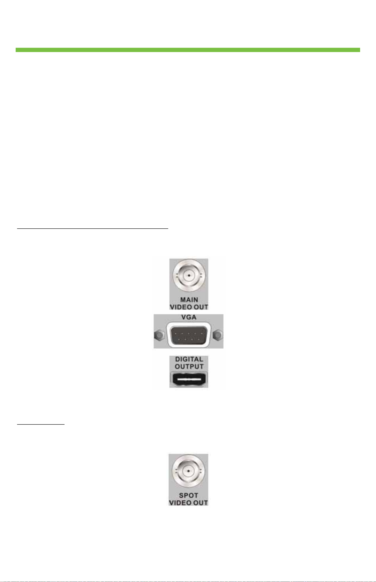
Main Monitor (BNC/ VGA/ Digital Output)
The DVR supports three different types of monitor outputs: BNC, VGA, or Digital Output. The main monitor
displays live image and playback recorded video in full-screen or split-window format.
Note: The DVR can only connect to one main monitor at a time. There is no simultaneous display.
Spot Monitor
The BNC Spot Monitor connector allows users to connect an optional Spot Monitor to display full screen
video of all connected cameras in sequence.
GVI Securit
5
y
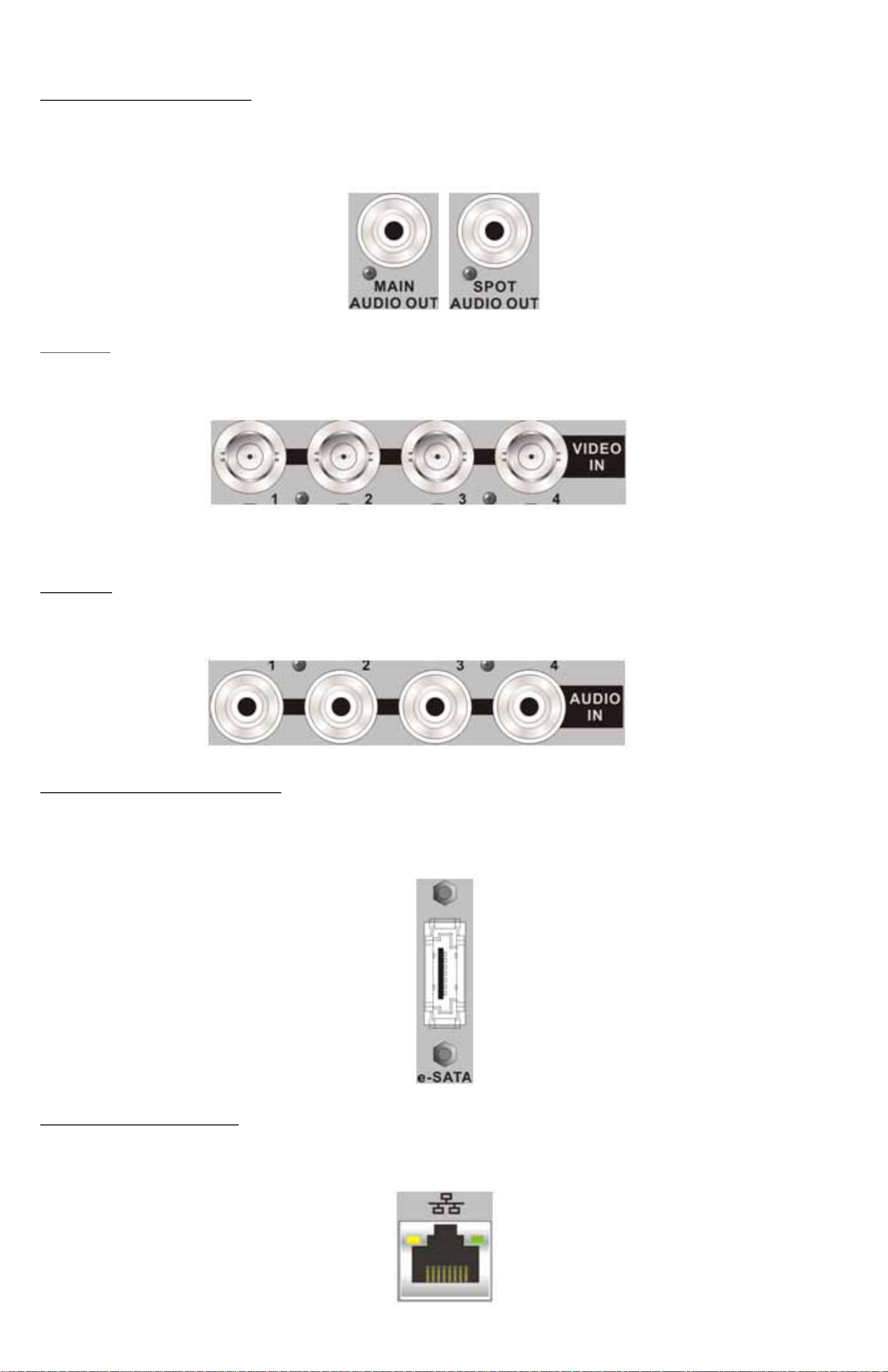
Audio Out – Main & Spot
Main & Spot Audio Out RCA connectors are used to connect the DVR with audio output devices (e.g.
amplified speakers). “Main Audio Out” uses the audio from the main monitor whereas “Spot Audio Out” uses
the audio from the Spot Monitor.
Video In
Use a group of BNC connectors for video input from installed cameras. The number of BNC connectors
equals the number of channels.
Ex: AR-6040
Note: The DVR detects a video source and automatically adjusts the system to a NT SC or PAL.
Audio In
A group of RCA connectors is provided for audio input of corresponding cameras. The number of connectors
equals the number of channels.
Ex: AR-6040
e-SATA (16CH models only)
The e-SATA port allows users to connect an external SATA device for recorded video backup. (e-SATA port
may not be active based on the FW release. Please contact GVI Security Tech Support Team to learn more
about to have e-SATA port activated.)
LAN Connector (RJ-45)
The DVR is capable of networking. Once the unit is connected to the LAN network, users can remotely
access the unit through Internet Explorer.
GVI Securit
y
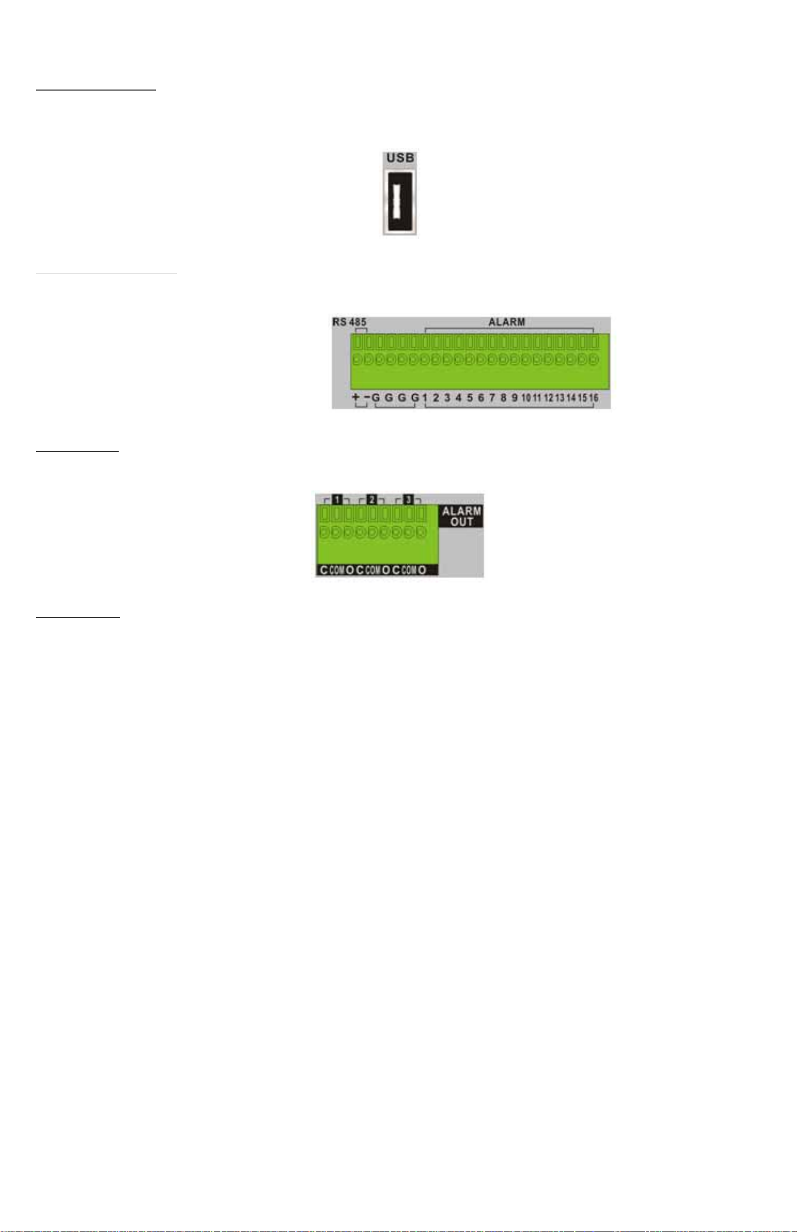
USB Connector
There is one USB port on the back panel. Connect USB devices such as a USB mouse or USB memory device
to this port.
6
RS-485 & Alarm In
The terminal block connector allows the ports to connect RS-485 and Alarm In devices.
Ex: AR-6160
Alarm Out
Connect up to three sets of alarm out devices to the alarm out terminal block.
Power Jack
The DVR has a 12V DC power connection jack. Connect the power adapter provided with the unit.
GVI Securit
y
3. OSD Operation
Prior to operating the DVR, setup the general configuration. The following subsections introduce the function
keys located on the front panel and the general configuration of the DVR.
The regular displayed OSD information and its displayed positions are sho wn in the following figure. The title
of the channel displays on the top-left corner of the window either in full-screen mode or in multiple channel
modes. The current date/time information displays at the bottom-right corner of the screen. The operation
status displays in the functional status bar. Move the cursor to any status icon and its description displays.
CH1 CH2 CH3 CH4
CH5 CH6 CH7 CH8
CH9 CH10 CH11 CH12
7
CH13 CH14 CH15 CH16
2011.01.19 04:31:22 AM
3.1 Front Panel Introduction
The controls on the front panel enable users to control the unit and preset the programmable functions.
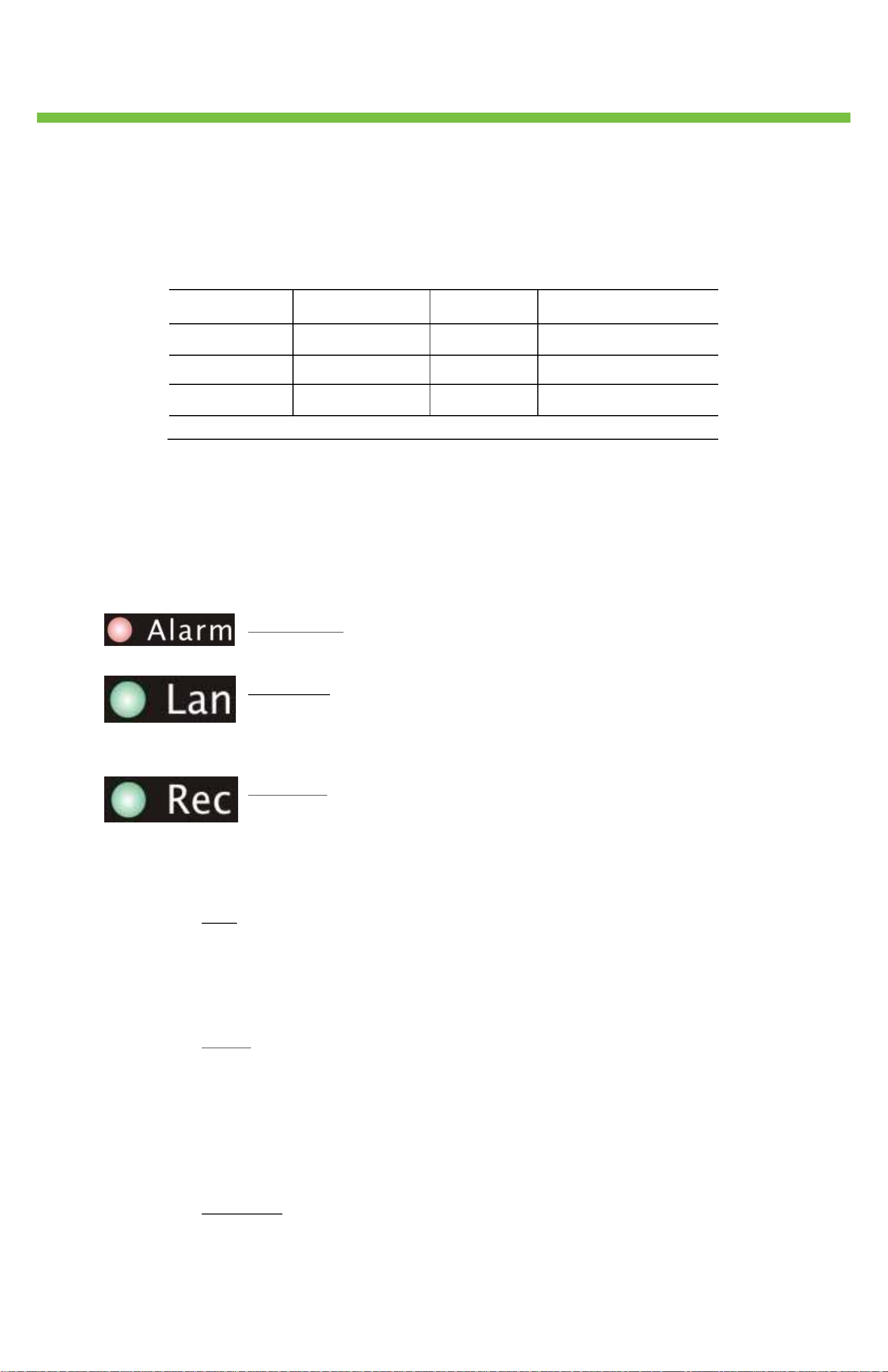
3.1.1 LED Definition
The LEDs on the front panel of the DVR are described as follow.
Alarm LED
The LED lights up when an alarm event triggers.
LAN LED
The LED lights up when the DVR is connected to a network and blinks when
the data is being transferred.
REC LED
The LED blinks while the DVR is recording.
3.1.2 Function Keys
This section describes the functional keys on the front panel of the DVR.
Play
Press Play once to begin playing recorded video. Press Play again to exit.
Note: According to the record setting, part of the latest video cannot be played back
because the video is still saved in the buffer.
Pause
Press Pause to freeze live video. The date/time information shown on the monitor
continues updating in this mode. Press PAUSE again to return to live mode.
Press Pause while playing the recorded video and the playback video pauses. Press
LEFT/RIGHT to move the recorded video reverse/forward. Press Pause again to return
to the live viewing mode.
Sequence
Press Sequence to start an automatic sequence display of video from all installed
cameras.
GVI Securit

8
y
Display
Press Display to select the preferred monitor display format. The available display
modes include: full-screen, 4-window split (2×2), 9-window split (3×3), and 16-
window split (4×4).
Menu
Press Menu to enter the OSD setup menu.
Search
In both Playback and Live mode, press Search to enter the Search menu to search and
playback recorded video by date/time or events. Press Search twice to instantly playback
the latest recorded videos.
Channel
In both Live and Playback modes, press Channel to view the corresponding video in full
screen. The number of the Channel keys corresponds to the number of cameras
supported by the unit.
In the OSD number keyboard, press keys 1~9 to input numbers 1~9, and press 10 to
input number 0.
Power
Press and hold Power to power or shutdown the DVR.
PTZ
Press PTZ to enter PTZ control mode. In PTZ Control mode, press “1” to access the
Preset Settings menu. For 16CH models, press keys 11~16 to quickly access preset
points 1~6. In Zoom mode, press the direction keys to move in the desired directions.
Lock
When password protection is disabled, press Lock for five seconds to lock up the
system. Press and hold the Exit key for five seconds again to unlock the system.
Note: Enter the OSD menu and go to “System” “User Information” to enable or
disable the password protection.
Spot
In Live mode, press Spot to enter Spot Monitor control mode.
Direction Keys
In the OSD setup menu, the LEFT/ RIGHT keys are used to move the cursor to the
previous or next fields. To change the value in the selected field, press the UP/ DOWN
keys.
Enter
In the OSD setup menu or selection interface, press Enter to confirm the selection.
In live full-screen view mode, press Enter to view a 2x zoomed image; press it again to
exit the Zoom mode.
Exit
Press Exit to cancel or exit from certain modes or the OSD setup menu.
GVI Securit

y
3.2 Enter OSD Setup Menu
Customize the DVR configuration by entering the intuitive Graphical User Interface (GUI) OSD setup menu.
Press MENU and select an account to login. Enter a corresponding password. The preset password for the
administrator account “admin” is “1111”.
NOTE: Change the preset password to prevent unauthorized access to the unit.
An icon displays at the status bar showing the privilege level of the account, which ranks from 1 to 8. Under
the logout condition, the “Guest” icon displays.
There are two types of logout procedures. Manually logout by pressing the Exit key in Live mode or
automatically logout when keys are not pressed for 5 minutes in Live/Menu mode.
3.2.1 User Information
9
The DVR provides the option to create up to seven sets of usernames and passwords
with customized authority, excluding the preset “admin” account. From the Main Menu,
select “System” “User Information” and the menu displays as follows:
USER INFORMATION
ENABLE PASSWORD
USER SETUP
PRIVILEGES
LOAD DEFAULT
Enable Password
Select “ON” to request username and password for accessing functions listed in
Authority Setup menu or select “OFF” to allow free access.
User Setup
ON
NO
Setup a customized account, password, and privilege level in this menu. The account
name is case sensitive. The privilege level rank is from levels 1~8, and level 8 has the
highest privilege. Alternatively, select “DISABLE” to stop using the account.
Note: Users cannot change the username and authority level of the preset “admin”
account.
Privileges
Setup the privilege level for accessing the functions listed in this menu. The functions
include: Playback/Search, PTZ Control, Live Operation, Spot Monitor, Export, Main
Menu, System, Network, Device, Record, Event, and Shutdown. The privilege level is
ranked from levels 1~8, and level 8 has the highest privilege. Alternatively, select “ALL
LEVELS” to allow free access.
Note: Users cannot set the Menu Access to “ALL LEVELS”.
When the account does not have authority to access certain functions, an error
message displays on the screen.
Load Default
Select “Yes” to load the default setting.
3.3 Power Up/Shutdown the DVR
If shutting down the DVR for any reason, use the proper shutdown and powering procedures to avoid
damaging the DVR.
GVI Securit

y
Powering the Unit
Plug in the power adapter that came with the package and the DVR begins to boot.
The VideoPlus logo, color bar, and syst em checking information display on the monitor and then disappear
when the unit is completely powered up.
10
Restart/Shutdown the Unit
Press MENU and input the username and password that has sufficient authority to access the OSD setup
menu. Select “SHUTDOWN” in the OSD setup menu and press Enter to go to the Shutdown menu, which
displays as follows.
Shutdown
RESTART
SHUTDOWN
“RESTART”
Select this item to reboot the unit. The VideoPlus logo, color bar, and system checking information display on
the monitor until the unit completely restarts.
“SHUTDOWN”
Select this item to shut down the unit. Do not remove the power during shutdown until the message “You
can safely turn off DVR now!” displays.
3.4 System Date/Time Setting
Users can set the current date, time, and other OSD parameters in the DATE/TIME/LANGUAGE menu
(under System menu). The login account should have privilege to access the System menu. In the OSD setup
menu, select “System” and press Enter. Then select “DATE/TIME/LANGUAGE;” the menu displays as follows.
DATE/TIME/LANGUAGE
DATE
TIME
TIME ZONE
DATE FORMAT
TIME FORMAT
DAYLIGHT SAVING TIME
NETWORK TIME SYNC
LANGUAGE
2011/01/21
PM 10:39:26
OFF
YYYY/MM/DD
12 HR
ENGLISH
3.4.1 Set Date/Time
Set DATE/TIME
Select “DATE” / “TIME” and press Enter to adjust the settings. LEFT/RIGHT keys are
used to move the cursor to the previous or next field, Enter is for confirming the
selection, and use the UP/DOWN keys to change the value in the selected field.
Note: The new date/time setting applies to recording new video. The date and time of
previously recorded video does not change. If changing time settings, format the HDDs
to avoid database corruption.
DATE FORMAT
This function allows users to set the OSD display type of the date. There are three
options from which to select: “YYYY/MM/DD”, “MM/DD/YYYY”, or “DD/MM/YYYY”.
“YYYY” represents “Year”, “MM” represents “Month”, and “DD” represents “Day”.
TIME FORMAT
Users can set the time format to “12 HR” or “24 HR”. Use the UP/DOWN keys to
change the format.
GVI Securit

11
y
3.4.2 Daylight Savings Time
APPLY DST
This feature temporarily adjusts the time in certain regions to observe Daylight Saving
Time. Select “ON” to enable or “OFF” to disable the feature.
If the feature is disabled, the DST Start/End time and DST Bias are not available.
Note: If this function is enabled, the date/time information displays on the screen with a
DST icon when playing back recorded video or searching video in the event list. “S”
indicates summertime and “W” indicates wintertime.
DST BEGIN/END
Use the options to program the daylight saving duration. Use the LEFT/RIGHT keys to
move the cursor to the next or previous field and the UP/DOWN to change the
settings in the selected field.
3.4.3 Network Time Sync
TIME ZONE
Select “TIME ZONE” to setup the correct time zone for the location.
Note: The “TIME ZONE” must be set to the correct local time zone or the
“NETWORK TIME SYNC” option does not function correctly.
NETWORK TIME SYNC
After setting up the correct time zone, the “NETWORK TIME SYNC” option is
accessible. Select “TIME SERVER” to setup the time server. The default time server is
time.nist.gov, but the users can change to any other time server if preferred. A list of IP
addresses of the time servers is listed below.
129.6.15.28 129.6.15.29 132.163.4.101
132.163.4.102 132.163.4.103 128.138.140.44
192.43.244.18 131.107.1.10 69.25.96.13
206.246.118.250 208.184.49.9 64.125.78.85
207.200.81.113 64.236.96.53 68.216.79.113
After setting the time server, set “MANUAL INTERVAL” to “YES” to sync the time
immediately. The time sync can also be updated periodically. Set “INTERVAL” to
“ON” and the time automatically syncs once an hour.
GVI Securit

12
y
3.5 Record Schedule/Quality Setting
The Record menu allows users to set recording quality, recording schedules, and other recording parameters.
Login with an authorized account to access the Record menu. In the Main menu, select “Record” and press
Enter; the following menu displays.
Record
RECORD SETUP
SCHEDULING
QUALITY / FPS
ADVANCED SETUP
AUTO SCHEDULE SETUP
DISK END MODE
ERASE DATA
AUTO SCHEDULE
OVERWRITE
3.5.1 Record Setup
The RECORD SETUP menu allows users to setup record resolution. The relative
record settings, such as preset configuration, follow the record mode setting. See the
example below of the display menu.
RECORD SETUP
RESOLUTION
CBR/VBR
FORMAT
TOTAL FPS
720X480 (D1)
CBR
H.264
60
Select RESOLUTION of the video from 720X480 (D1), 720X240 (Half DI),
and 352X240 (CIF) for NTSC systems. If the video system is PAL, the
options are 720X576 (D1), 720X288 (Half DI), and 352X288 (CIF)
Set the recording bit rate as CBR (Constant Bit Rate) or VBR (Variable Bit
Rate)
FORMAT of the video is H.264
TOTAL FPS changes automatically according to the selected RESOLUTION
Use VBR encoding when reliable video quality is the highest priority.
Note: Since a VBR file does not have a fixed size, the HDD space usage cannot be
calculated and, therefore, the “Advanced Record” setting is not supported for VBR
mode. Therefore, if the “Advanced Record” is selected as the default record
configuration, the selectio n of this menu item is automatically set as “CBR”.
3.5.2 Sch eduling
Use the SCHEDULING menu to set the day and night time or weekend recording
schedule. Select “SCHEDULING” from the Record menu and press Enter; the following
menu displays.
DAY BEGIN
DAY END
NIGHT BEGIN
NIGHT END
WEEKEND SCHEDULE
WEEKEND BEGIN
WEEKEND END
SCHEDULING
AM 06:00
PM 06:00
PM 06:00
AM 06:00
ON
Fri PM 06:00
Mon AM 06:00
GVI Securit
 Loading...