

Page 1
GVD HD NVR Hardware
Quick Installation Guide
Page 2
1
Hardware Quick Installation Guide
Hardware Installation
M90 Series
Recommended HDD for GVD NVR
M100 Series
M150 Series
M200 Series
M350 Series
M600 Series
Recording HDDs Initialize Procedures
Disable System Protection
Date & Time/Time Zone Setup
Network Setup
Screen Resolution Setup
Enable System Protection
How to Create Raid 5
(for M600 series only)
Change Boot Priority
HDD Installation Guide
Software Configuration
Create Volume for Recording
Add Camera Automatically
Setup Motion Recording
Troubleshooting FAQ
Appendix.
Content
2
3
4
5
11
12
13
14
15
17
18
21
23
26
12
16
26
32
34
2
7
10
8
Page 3
Recording data is one of the most important part in security industry and hard
disk would be one of the most important component if users want to have their
recording data safely stored.
It is always recommended to use the hard disk model that GVD certifies, user
can find the updated list from the URL below :
http://www.gvdigital.com/document/Support_Lists/GVD_Certified_HDD_List.pdf
2
Hardware Quick Installation Guide
Recommended HDD for GVD NVR
*Please refer to the Appendix page for HDD Installation Guide
Page 4
3
Hardware Quick Installation Guide
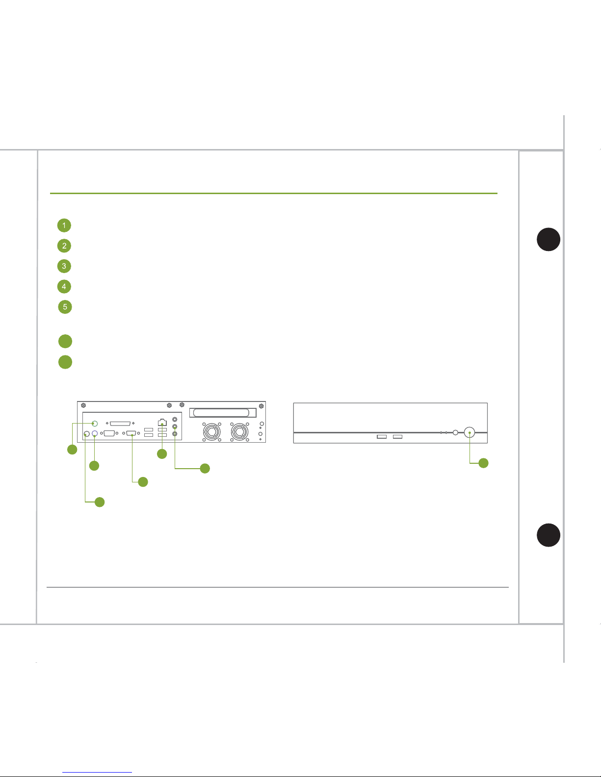
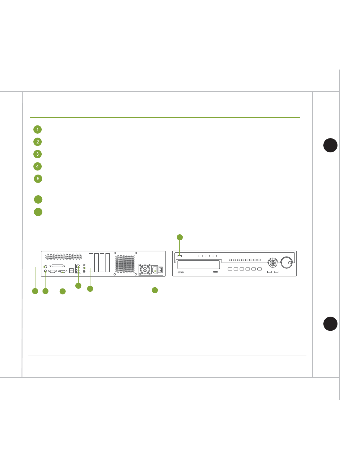
Hardware Installation M90 Series
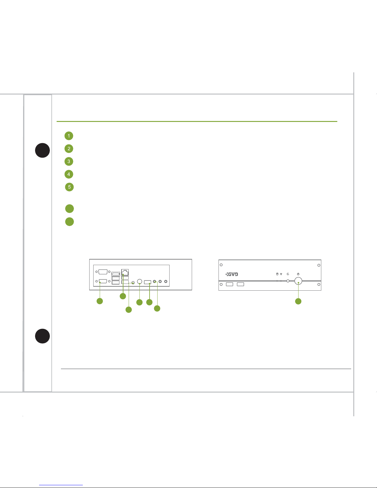
Connect the keyboard to the Keyboard PS2 port (purple)/USB port.
Connect the mouse to one of the USB port.
Connect the display monitor to the VGA port.
Connect the power cord to the AC power socket at the rear panel of the unit.
Plug in a CAT-6 UTP cable to the RJ-45 Gigabit LAN port, and connect the other
end of the cable to a switch connecting to the camera network.
Plug in the speaker to the audio output port if necessary.
Plug in the power cord to the AC power socket of power distribution unit and the
system will turn on automatically.
6
7
Empowering Megapixel
1
7
4
6
2
3
5
* Please DO NOT plug any USB device other than keyboard & mouse to the machine
before entering operating system.
* For M90 series, it can support decoding resolution from D1 up to 3M
* GVD will not be liable for any malfunction of the system if customer installed any non-certified
3rd-party application in the system.
Page 5
4
Hardware Quick Installation Guide
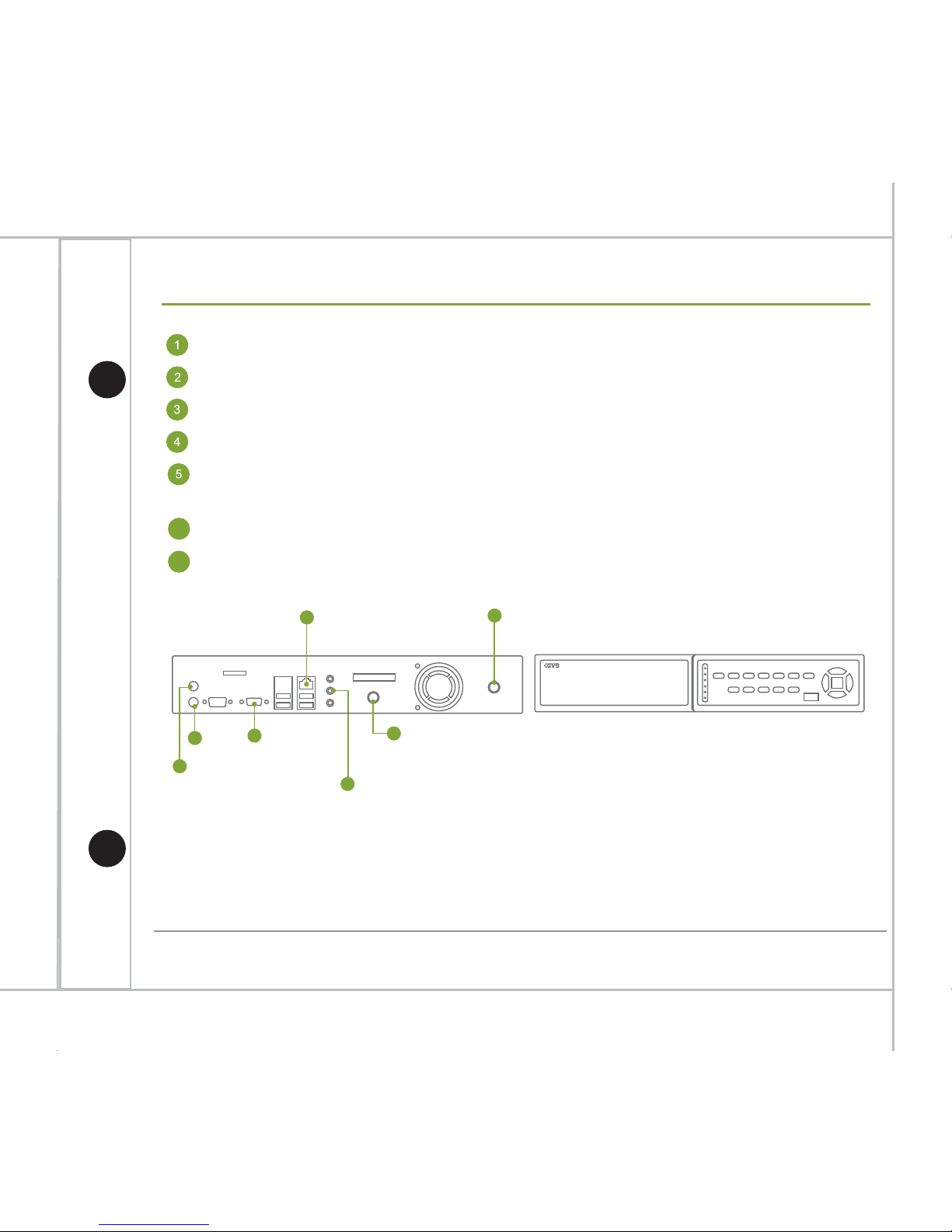
Hardware Installation M100 Series
Connect the keyboard to the Keyboard PS2 port (purple)/USB port.
Connect the mouse to the mouse PS2 port (green)/another USB port.
Connect the display monitor to the VGA port.
Connect the power cord to the AC power socket at the rear panel of the unit.
Plug in a CAT-6 UTP cable to the RJ-45 Gigabit LAN port, and connect the other
end of the cable to a switch connecting to the camera network.
Plug in the speaker to the audio output port if necessary.
Plug in the power cord to the AC power socket of power distribution unit and the
system will turn on automatically.
6
7
4
1
2
3
5
6
7
* Please DO NOT plug any USB device other than keyboard & mouse to the machine
before entering operating system.
* For M100 series, it can support decoding resolution from D1 up to 3M.
* GVD will not be liable for any malfunction of the system if customer installed any non-certified
3rd-party application in the system.
Page 6
5
Hardware Quick Installation Guide
Hardware Installation M150 Series
Connect the keyboard to the Keyboard PS2 port (purple)/USB port.
Connect the mouse to the mouse PS2 port (green)/another USB port.
Connect the display monitor to the VGA port.
Connect the power cord to the AC power socket at the rear panel of the unit.
Plug in a CAT-6 UTP cable to the RJ-45 Gigabit LAN port, and connect the other
end of the cable to a switch connecting to the camera network.
Plug in the speaker to the audio output port if necessary.
Plug in the all power cords to the AC power socket of power distribution unit and
system will turn on automatically.
6
7
6
7
5
4
4
1
2
* Please DO NOT plug any USB device other than keyboard & mouse to the machine
before entering operating system.
* For M150 series, it can support decoding resolution from D1 up to 3M.
* GVD will not be liable for any malfunction of the system if customer installed any non-certified
3rd-party application in the system.
Page 7
6
Hardware Quick Installation Guide
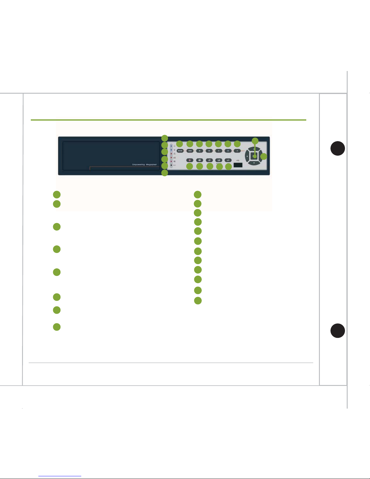
Hardware Installation M150 Series
1
1
2
2
3
4
5
6
7
8 9
10
11 12 13
14 15
16
17 18
19
20
Reset
HDD Fail
14
Manual Recording
15
T oggle Tour
16
Toggle Full Screen
17
Switch Pattern
18
Back to Live
6
Power LED
5
Recording LED
On when NVR is recording
Off when NVR is not recording
4
Alarm
On when NVR has active alarm
Off when NVR does not have active alarm
3
Video Loss
On when there is channel in video loss state
Off when there is no channel in video loss state
On when there is HDD in exception state
Off when all HDDs are in normal state
19
1x1 Display
20
Change Viewer Focus
9
Step by Step Backward Playback
10
Step by Step Forward Playback
11
Playback Backward
12
Pause
13
Playback Forward
7
Long Duration Playback
(Click once to playback forward/backward 5 mins)
8
Short Duration Playback
(Click once to playback forward/backward 30 secs)
Page 8
7
Hardware Quick Installation Guide
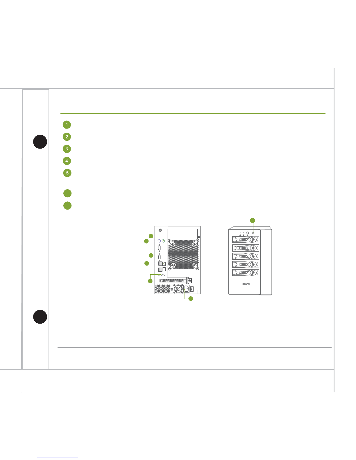
Hardware Installation M200 Series
Connect the keyboard to the Keyboard PS2 port (purple)/USB port.
Connect the mouse to the mouse PS2 port (green)/another USB port.
Connect the display monitor to the VGA port.
Connect the power cord to the AC power socket at the rear panel of the unit.
Plug in a CAT-6 UTP cable to the RJ-45 Gigabit LAN port, and connect the other
end of the cable to a switch connecting to the camera network.
Plug in the speaker to the audio output port if necessary.
Plug in the power cord to the AC power socket of power distribution unit and the
system will turn on automatically.
6
7
1
2
3
5
6
4
7
* Please DO NOT plug any USB device other than keyboard & mouse to the machine
before entering operating system.
* For M200 series, it can support decoding resolution from D1 up to 3M.
* GVD will not be liable for any malfunction of the system if customer installed any non-certified
3rd-party application in the system.
Page 9
8
Hardware Quick Installation Guide
Connect the keyboard to the Keyboard PS2 port (purple)/USB port.
Connect the mouse to the mouse PS2 port (green)/another USB port.
Connect the display monitor to the VGA port.
Connect the power cord to the AC power socket at the rear panel of the unit.
Plug in a CAT-6 UTP cable to the RJ-45 Gigabit LAN port, and connect the other
end of the cable to a switch connecting to the camera network.
Plug in the speaker to the audio output port if necessary.
Plug in the power cord to the AC power socket of power distribution unit and the
system will turn on automatically.
6
7
* Please DO NOT plug any USB device other than keyboard & mouse to the machine
before entering operating system.
* For M350 series, it can support decoding resolution from D1 up to 10M.
7
4
5
3
12
6
* GVD will not be liable for any malfunction of the system if customer installed any non-certified
3rd-party application in the system.
Hardware Installation M350 Series
Page 10
9
Hardware Quick Installation Guide
Hardware Installation M350 Series
1
1
2
2 3 4 567
8 9
10 11 12 13 14 15
16 17 18 19 20 21
22
23
24
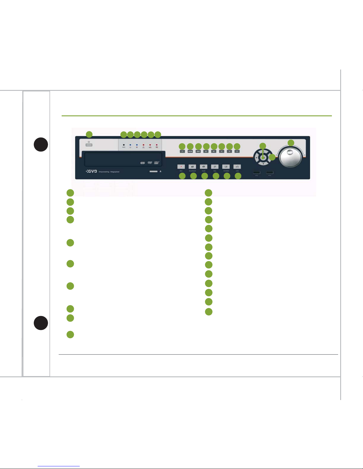
Power
11
Step by Step Backward Playback
12
Step by Step Forward Playback
13
Playback Backward
14
Pause
15
Playback Forward
16
Manual Recording
17
Snapshot
18
T oggle Tour
19
Toggle Full Screen
20
Switch Pattern
21
Back to Live
22
23
1x1 Display
Change Viewer Focus
Reset
3
Power LED
4
Recording LED
5
Alarm
On when NVR is recording
Off when NVR is not recording
On when NVR has active alarm
Off when NVR does not have active alarm
6
Video Loss
On when there is channel in video loss state
Off when there is no channel in video loss state
7
HDD Fail
8
Switch Monitor
9
Long Duration Playback
On when there is HDD in exception state
Off when all HDDs are in normal state
24
Rewind Dial
Outer :
Inner :
(Click once to playback forward/backward 5 mins)
10
Short Duration Playback
(Click once to playback forward/backward 30 secs)
Left = Playback backward with speed change
Right = Playback forward with speed change
Left = Playback backward frame by frame
Right = Playback forward frame by frame
Page 11
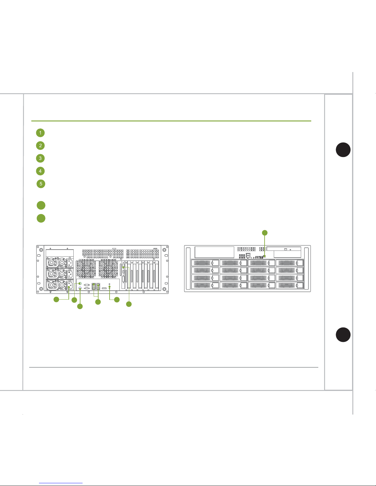
Connect the keyboard to the Keyboard PS2 port (purple)/USB port.
Connect the mouse to the mouse PS2 port (green)/another USB port.
Connect the display monitor to the VGA port.
Connect the power cord to the AC power socket at the rear panel of the unit.
Plug in a CAT-6 UTP cable to the RJ-45 Gigabit LAN port, and connect the other
end of the cable to a switch connecting to the camera network.
Plug in the speaker to the audio output port if necessary.
Plug in the all power cords to the AC power socket of power distribution unit and
system will turn on automatically.
6
7
2
5
6
1
4
3
* Please DO NOT plug any USB device other than keyboard & mouse to the machine
before entering operating system.
* For M610 series, it can support decoding resolution from D1 up to 1.3M.
For M620-M640 series, it can support decoding resolution from D1 up to 10M.
7
* GVD will not be liable for any malfunction of the system if customer installed any non-certified
3rd-party application in the system.
10
Hardware Quick Installation Guide
Hardware Installation M600 Series
Page 12
11
Hardware Quick Installation Guide
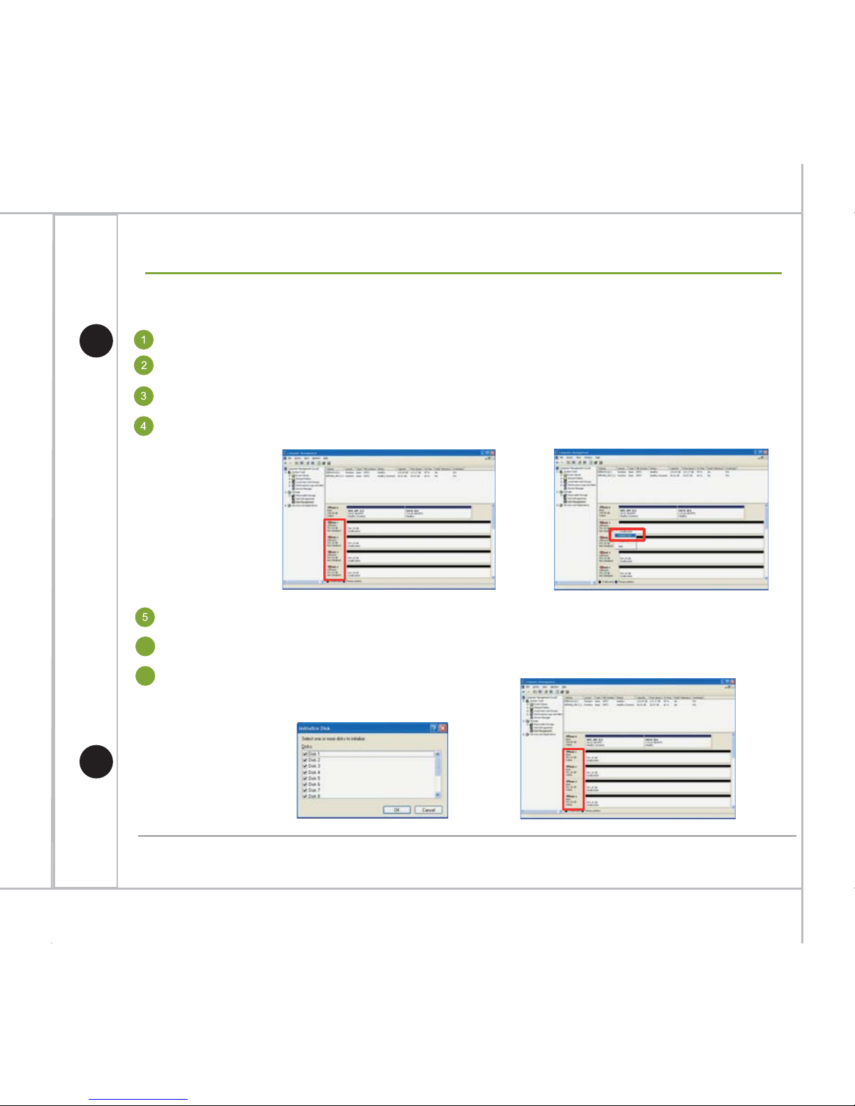
Recording HDDs Initialize Procedures
Log on to Windows®.
Right click “My Computer” icon on desktop.
Select the “Manage” option.
Select the item “Disk Management” under “Storage” node for initializing the newly
added HDDs.
Right click on “Non Initialized” HDDs then select the “Initialize Disk”.
User can check all checkboxes for the HDDs want to initialize then press “Ok”.
All HDDs will become “Online” status.
6
7
The newly added Hard Disks need to be initialized before volume creation
Non Inialized
Inialize Disk
Online
Page 13
Log on to Windows®.
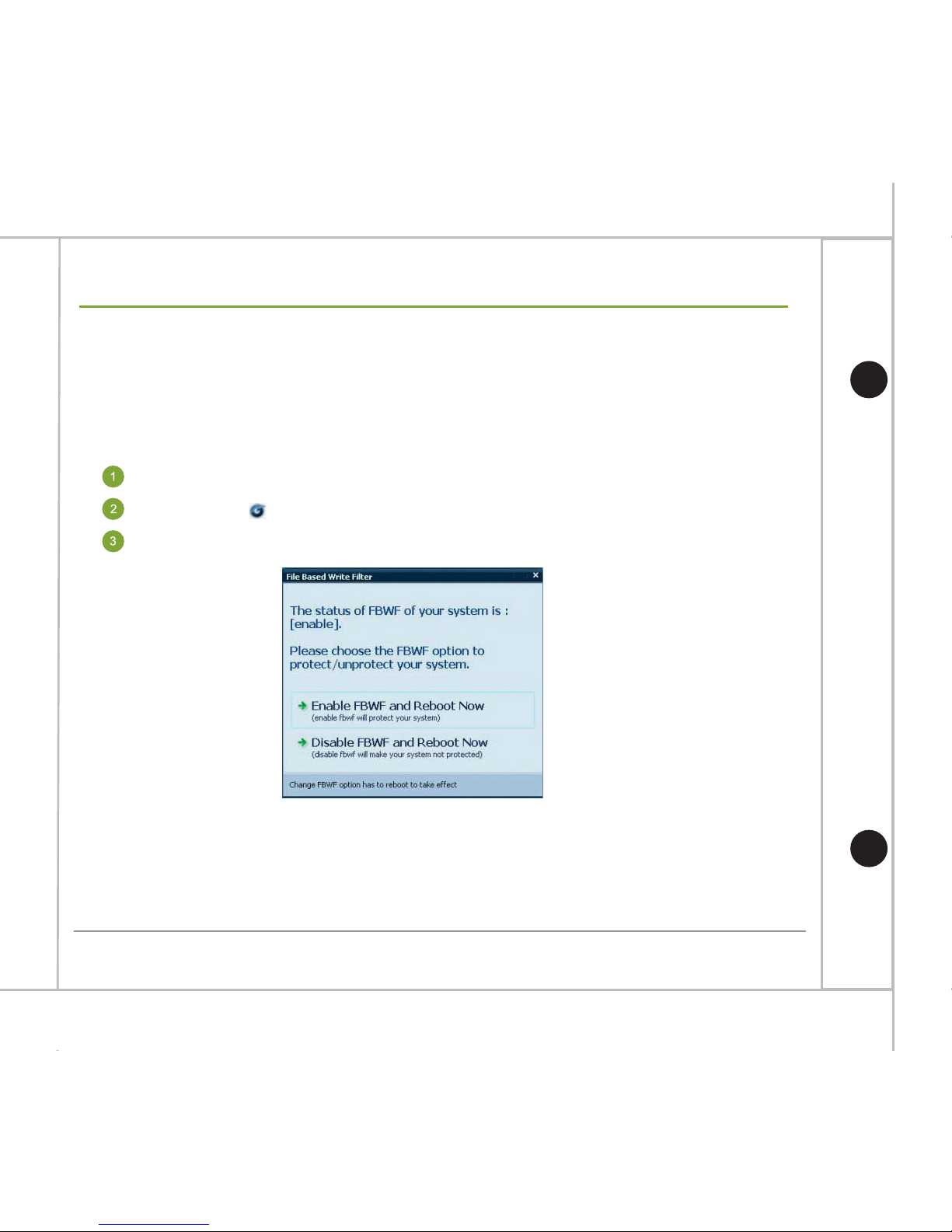
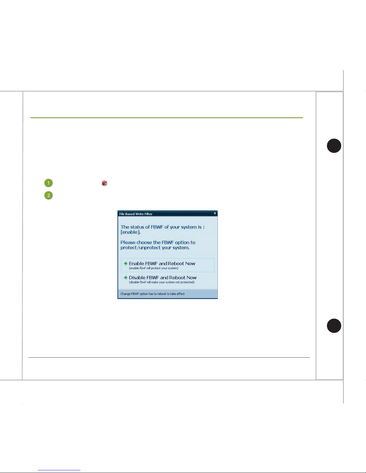
Before configure the system, user need to disable the system protection function first
and re-enable it after finishing configuration. Please follow the steps below to configure
the system:
After the reboot, user can start to configure the system as described in the following
pages.
*While in the system protection mode, all the changes made to the system will be gone after reboot.
Disable System Protection
Double click on the Windows Toolbar.
Click Disable FBWF and Reboot Now.
12
Hardware Quick Installation Guide
Software Configuration
Page 14
13
Hardware Quick Installation Guide
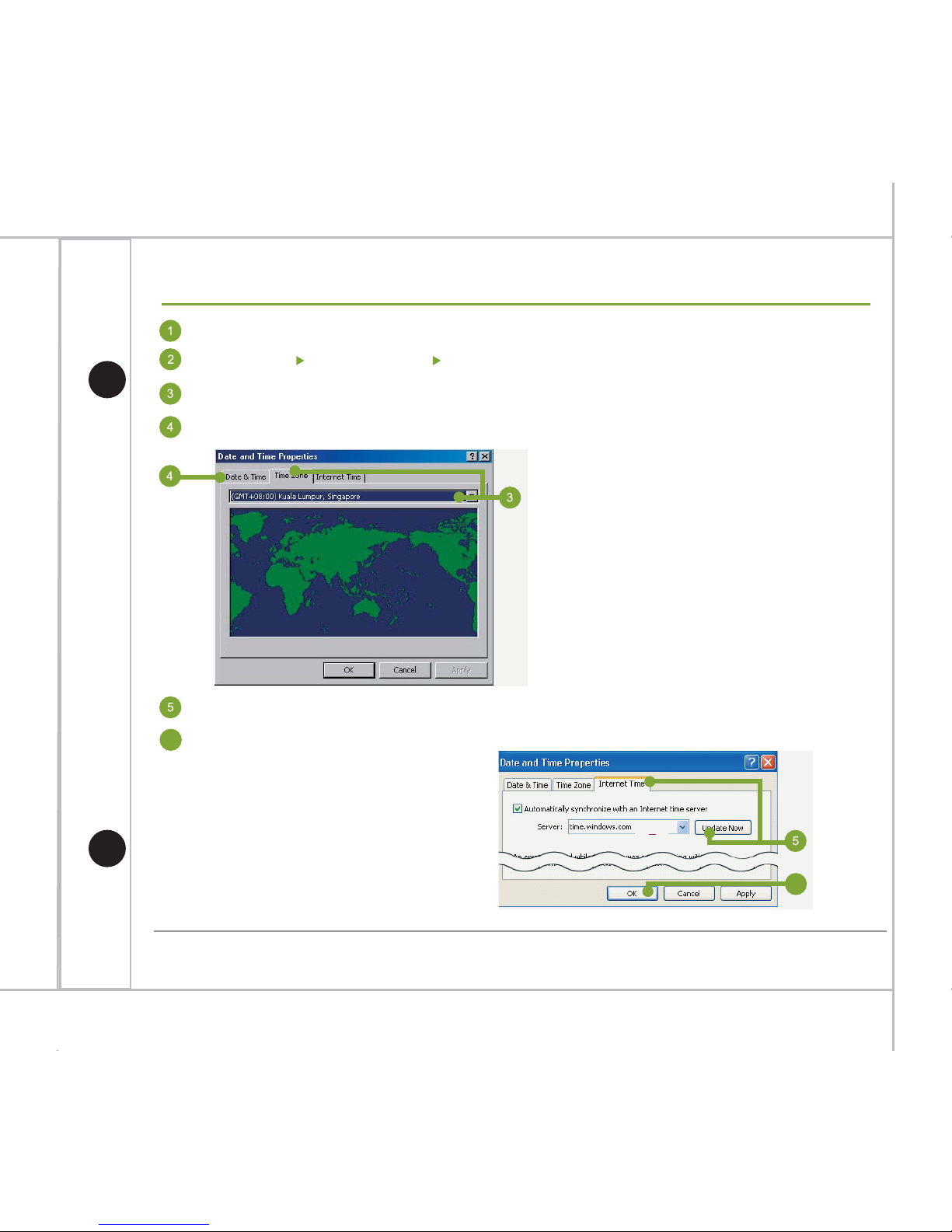
Date & Time/Time Zone Setup
Log on to Windows®.
Go to ‘Start Control Panel Date & Time’.
Select the ‘Time zone’ tab, set the correct time zone and apply.
Select the Date & Time tab, set the correct date & time and apply.
Select the ‘Internet Time’ tab and click ‘Update Now’ button to synchronize the time.
Press ‘OK’ to save the changes.
6
6
Page 15
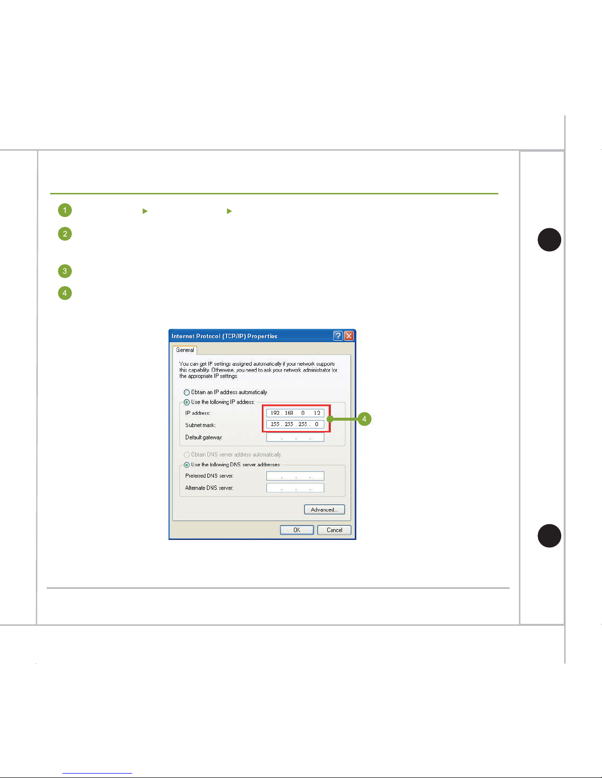
Go to ‘Start Control Panel Network’.
Right mouse click on the active connection icon and select ‘Properties’ from the
pop-up menu.
Select ‘Internet Protocol (TCP/IP) and then press ‘Properties’.
In the ‘General’ tab, set the preferred IP address and the subnet mask
then press ‘OK’.
*Before conducting the network configuration, please make sure the network environment is ready.
If the network is not available, contact your network administrator for further help.
14
Hardware Quick Installation Guide
Network Setup
Page 16
15
Hardware Quick Installation Guide
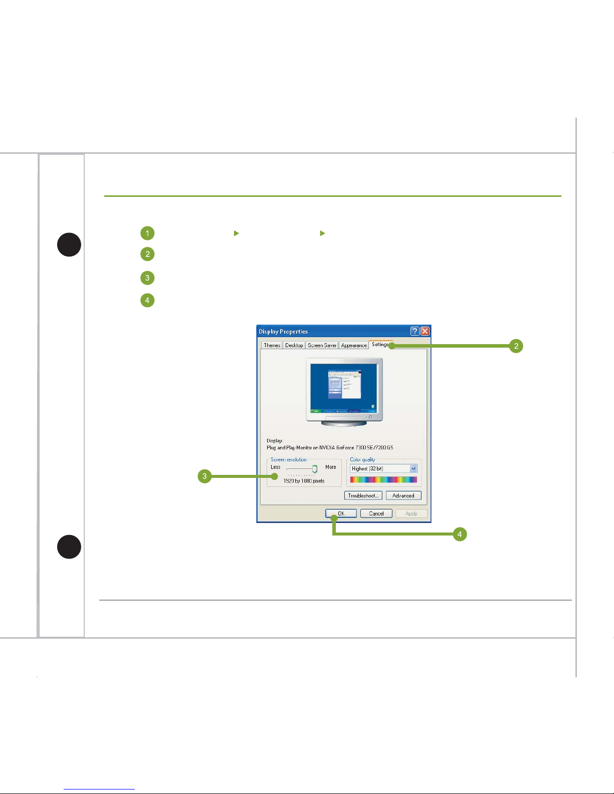
Screen Resolution Setup
Go to ‘Start Control Panel Display Properties’.
*The minimum supported screen resolution is 1280 x 1024.
Switch to Settings tab.
Change the ‘Screen resolution’ to 1680 x 1050 (recommend value).
Press ‘OK’ for saved the settings.
Page 17
16
Hardware Quick Installation Guide
Enable System Protection
Double click on the Windows Toolbar.
After the system has been configured, user needs to re-enable the system
protection function in order to keep the system away from harm. Please follow the
steps below to re-enable the system protection function:
After the reboot, the system will be in the system protection mode.
*In future, if system modification is necessary, please follow the steps “Disable System Protection”
in page 6.
Enable System Protection
Click Enable FBWF and Reboot Now.
Page 18
17
Hardware Quick Installation Guide
Create Volume for Recording
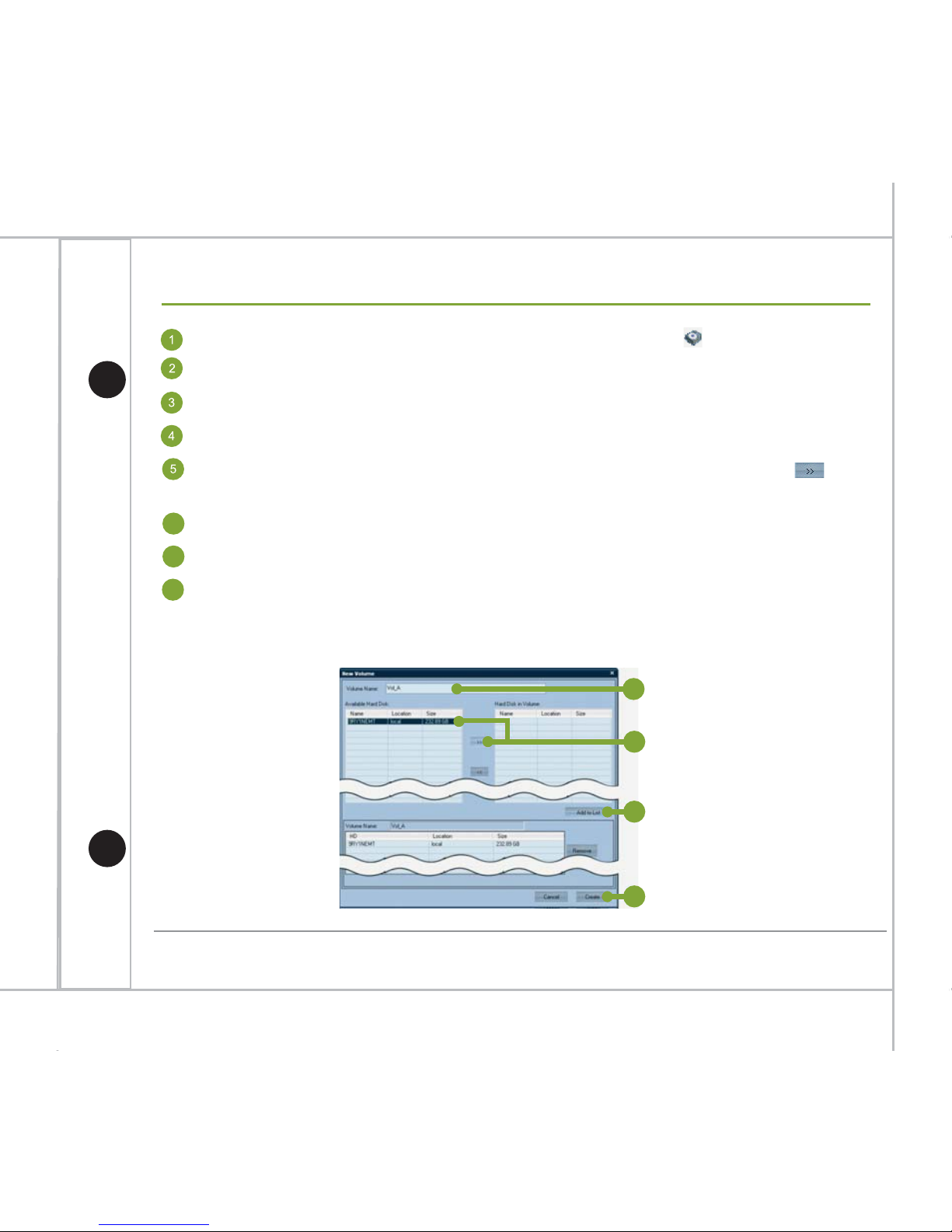
In Windows® desktop, double click the SCM program icon ( ).
Input default username
Admin and password 6001 to login.
In the SCM program, press the ‘New Volume’ button in the left panel.
Input the name of the volume in the ‘Volume Name’ field.
Select the preferred hard disk(s) from the available hard disk list. Click
(add) button to add the selected hard disk(s) to the list of ‘Hard Disk in Volume’.
Press ‘Add to List’ button to add the volume into queue for formatting.
Press ‘Create’ to continue.
6
7
The system shows a confirmation message – ‘Create Volume will reallocate your
hard disk and you will lose current data on the disk. Are you sure to keep doing
these jobs?’ Press ‘Yes’ to continue.
8
4
5
6
7
Page 19
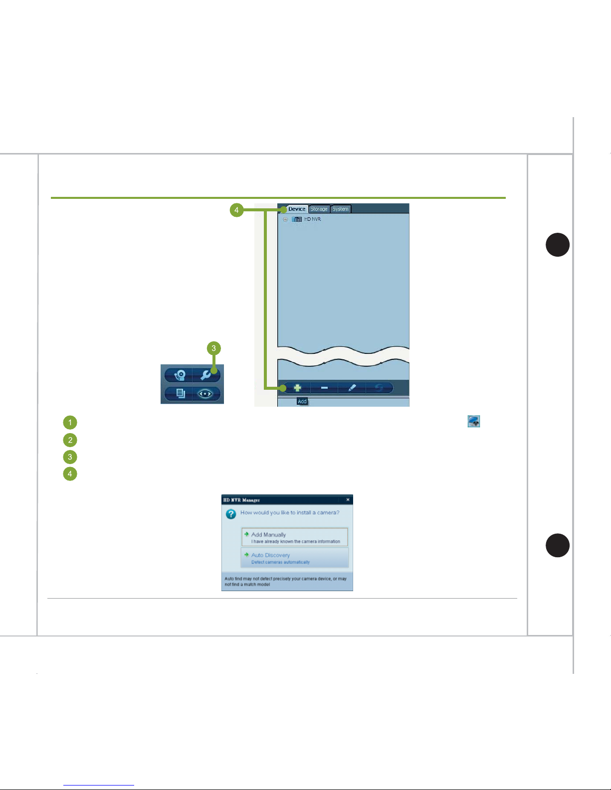
In Windows® desktop, double click the HD NVR Manager program icon ( ).
Log on HD NVR Manager using default username Admin and password 6001.
Go to Configuration Mode.
Select the ‘Device’ tab, click the ‘Add’ button.‘Add Camera Device’ dialog appears
as shown below.
18
Hardware Quick Installation Guide
Add Camera Automatically
Page 20
19
Add Camera Automatically (cont’d)
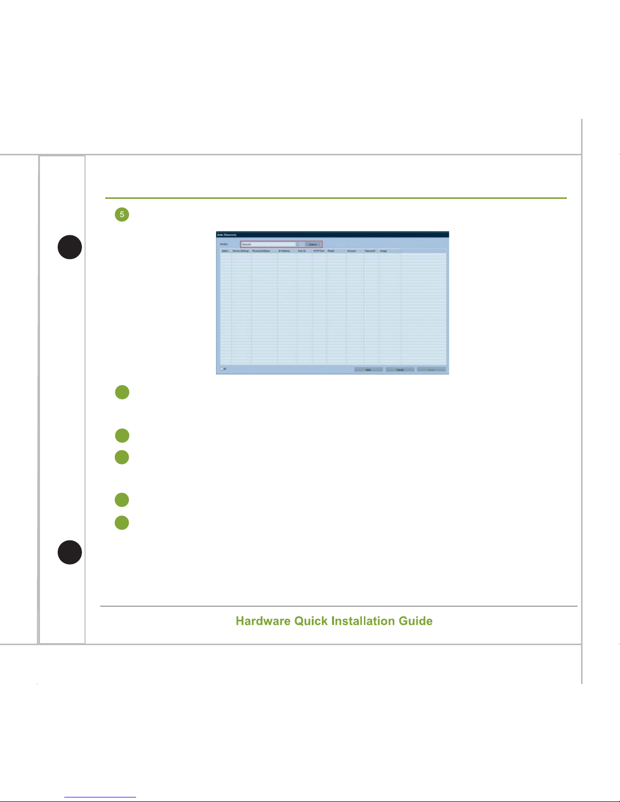
Select ‘Auto Discovery’ and the dialog appears as shown below.
Click the ‘Vendor’ dropdown box and select the preferred vendor name from the
list then pressing ‘Search’ to continue.
Input username and password of the vendor camera.
The system automatically searches all vendor’s connected IP cameras
in the network. The searching result will be listed.
6
7
Select the cameras to be installed and click ‘Import’ button.
8
The selected camera will be added to the system. A ‘Configuration
page’ shows for changing the setting of the cameras.
9
10
*Some cameras may not be added automatically. Refer to the details in the HD NVR user manual about
adding a camera manually.
Page 21
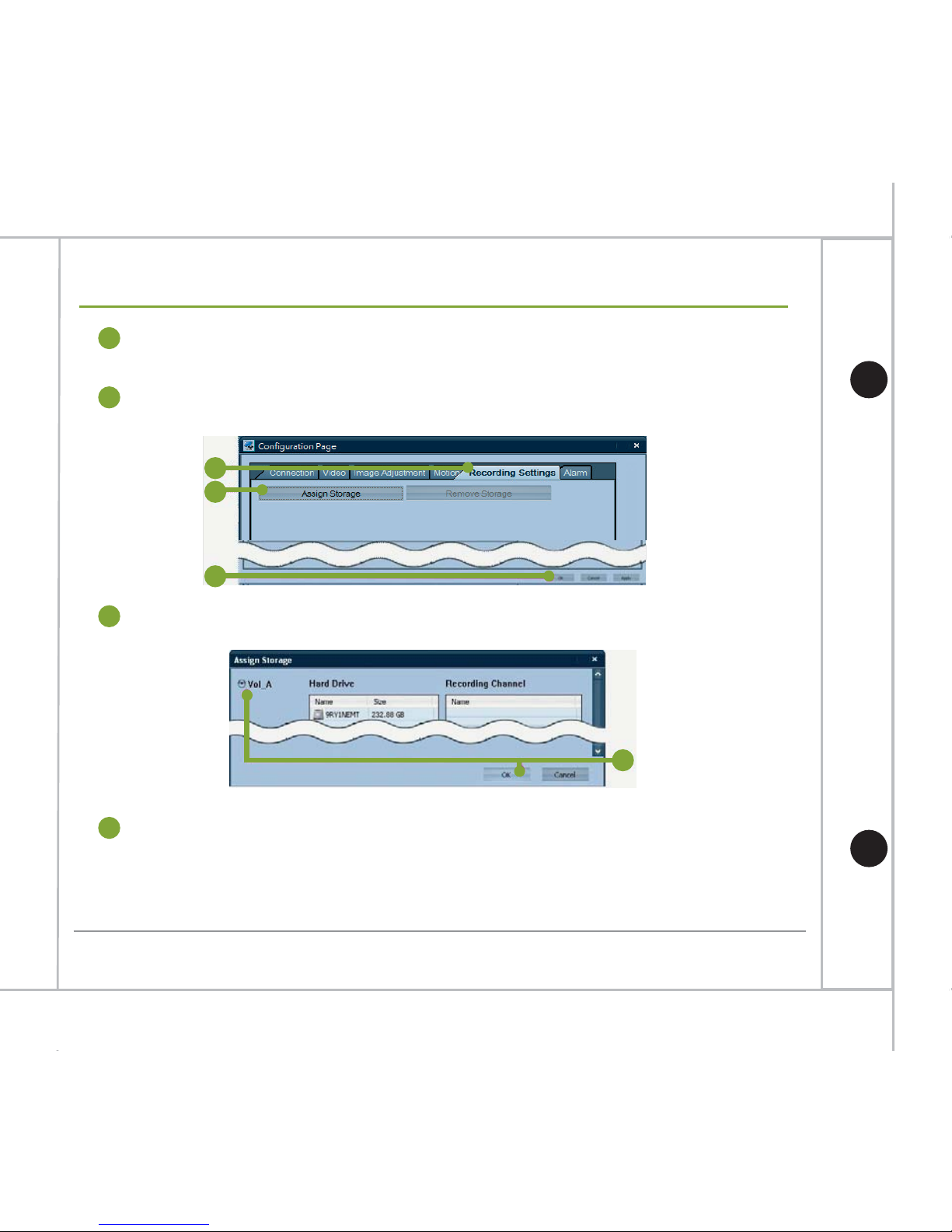
To activate the recording function of the camera, select the ‘Recording Settings’
tab in the Configuration page.
Press the ‘Assign Storage’ button. An ‘Assign Storage’ dialog appears.
Select the preferred volume and click ‘OK’.
12
13
Click ‘OK’ in the Configuration page to exit.
13
14
*To set up the schedule recording, refer to the HD NVR Manager user manual for more details.
11
14
20
Hardware Quick Installation Guide
Add Camera Automatically (cont’d)
11
12
Page 22
21
Hardware Quick Installation Guide
Setup Motion Recording
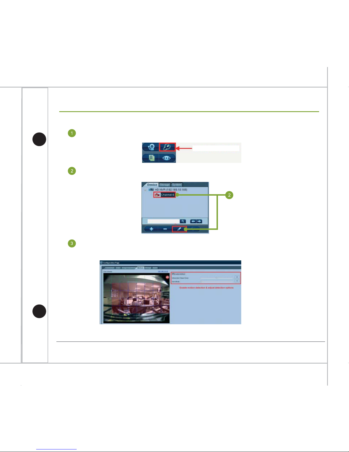
Motion Recording by Using Simple Alarm
Go to Configuration Mode
Select the camera that you want to setup for motion recording then click the
modify button.
In camera’s Configuration Page, select Motion tab to enable motion detection
of the camera and adjust detection sensitivity to the desired level.
*Different camera has different naming and ways to setup motion detection.
Configuration Mode
Page 23
22
Hardware Quick Installation Guide
Setup Motion Recording (cont’d)
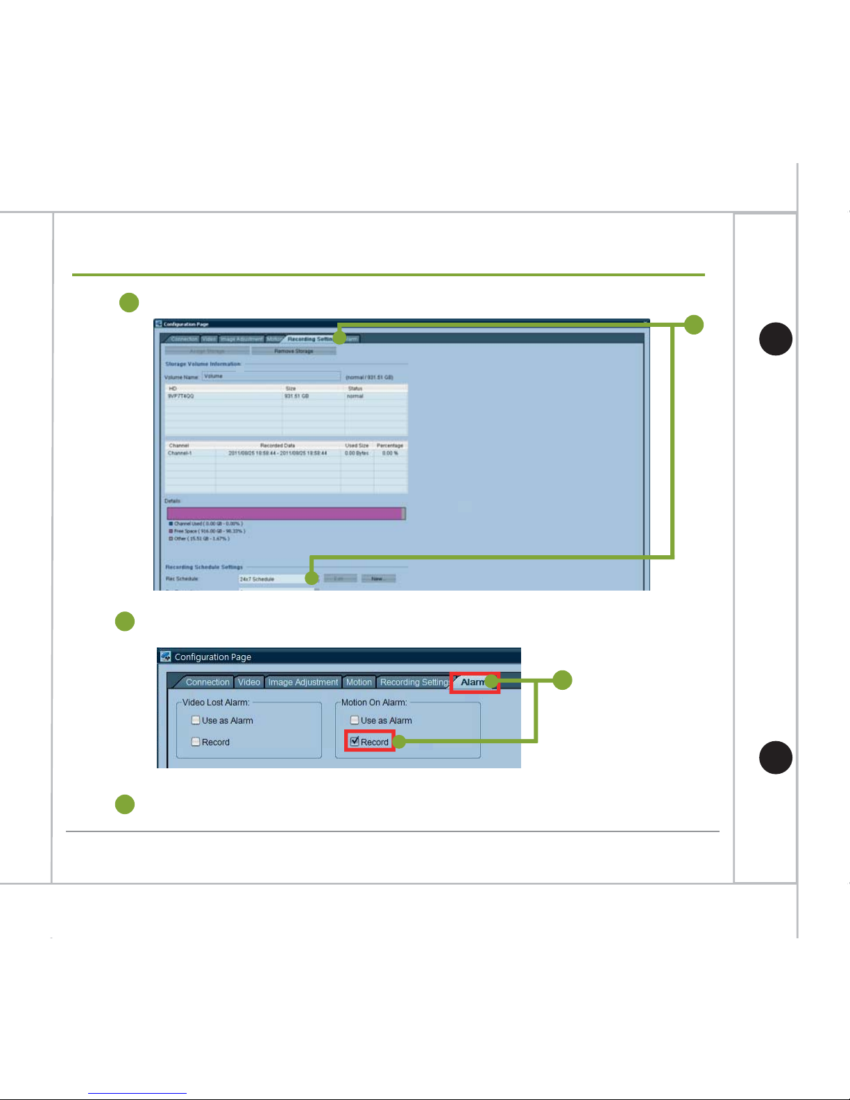
Select Recording Settings tab and disable camera’s recording.
Select Alarm tab to enable recording only when there is motion detected.
5
Click OK button to finish setup.
6
4
4
5
Page 24
23
Hardware Quick Installation Guide
12 & 16
12 & 13
12 & 15
Page 25
24
Hardware Quick Installation Guide
Why can't get video after adding camera?
Why the system IP address information of NVR manager screen shows
"0.0.0.0"?
Wrong user name and password
Wrong IP address
Firewall or Anti-Virus software blocks the communication port required on camera
(ex: 554 for Axis)
Network wire or power cable unplug
Total camera bandwidth is over network bandwidth.
The possible root cause might be:
There are two network interface cards in the system but HD NVR always uses the newly
added card by default. Disable one of the card and change IP setting if necessary then
restart the HD NVR service and HD NVR Manager software.
The network interface of NVR has not been connect to network switch yet. Please connect
the network interface cable to network switch then restart the HD NVR service and HD NVR
Manager software.
Why cannot find any camera using Auto Discovery method?
The IP address of camera does not have the same subnet with HD NVR (Ethernet card).
The camera may not be supported by HD NVR, please check the supported cameras list at
GVD website "http://www.gvdigital.com/support_device.html".
Troubleshooting FAQ (cont’d)
Page 26
25
Hardware Quick Installation Guide
Troubleshooting FAQ (cont’d)
How to install the Anti-Virus software for GVD HD NVR?
Before installing Anti-Virus software, please follow the instructions to disable the system
protection function first (refer to page 12) and enable it after finishing software installation
and configuration.
Since HD NVR writes enormous amount of data to recording hard drives, if antivirus
software scan those hard drives at the same time, it will seriously degraded the
system performance and even cause the system to crash and video data loss.
For those reasons, user must setup antivirus software not to scan the recording hard
drives to avoid degraded performance of the system.
HD NVR and cameras use port 80 as their transmission protocol, and the port was
scanned by Anti-Virus software as well. User must configure Anti-Virus software not
to scan the port or disable the HTTP checking function to avoid some Anti-Virus
software from creating enormous data files.
Page 27
26
Hardware Quick Installation Guide
This appendix chapter for M600 Series NVR only.
RAID System Creation
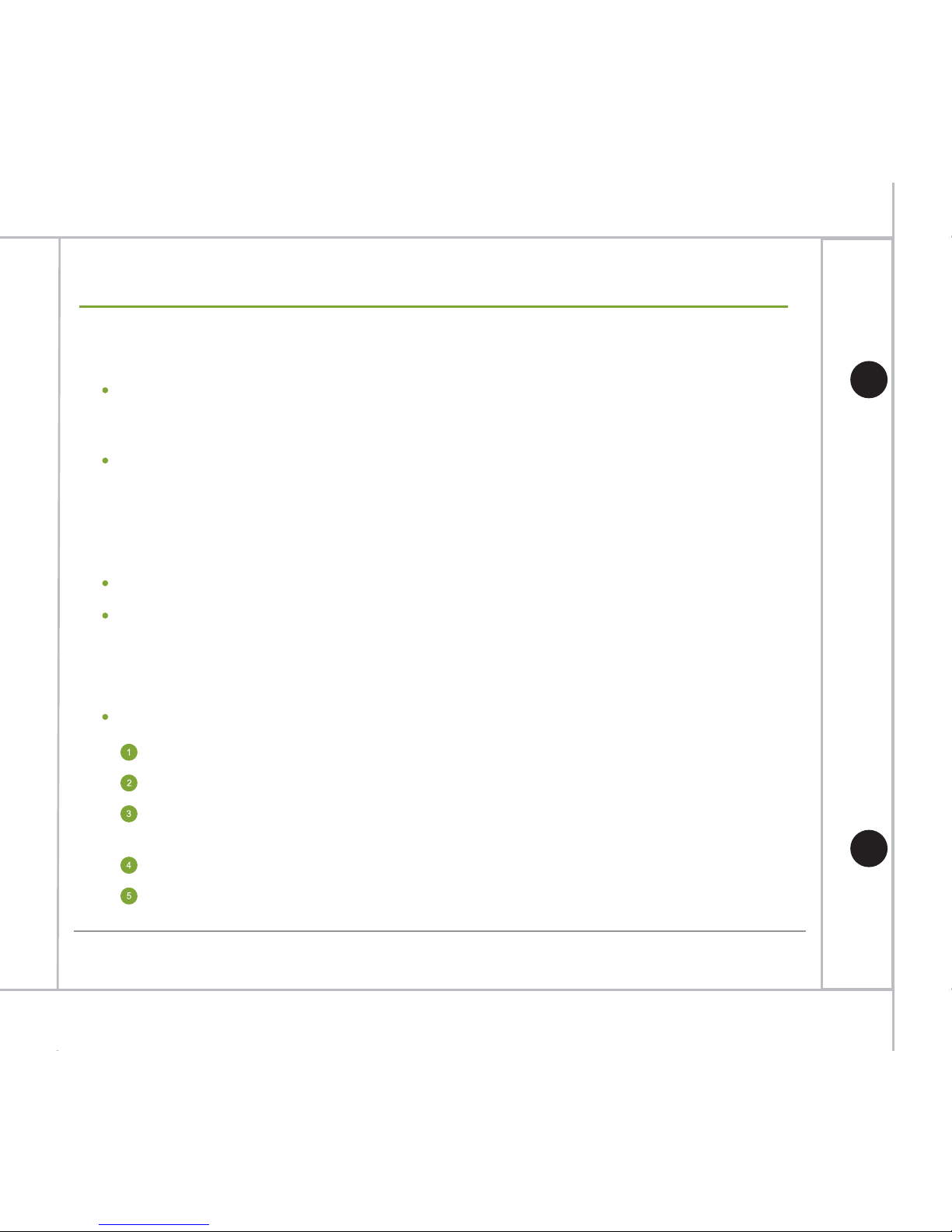
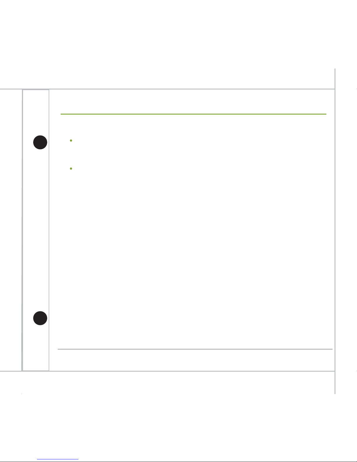
Open Areca HTTP Proxy Server GUI
Start Areca Technology Corp ArcHttpSrvGUI
Areca HTTP Proxy Server GUI
Select Controller #01(PCI),HTTP Port #81 and click “Launch Browser” button
Appendix. How to create RAID 5
Page 28
27
Hardware Quick Installation Guide
Appendix. How to create RAID 5
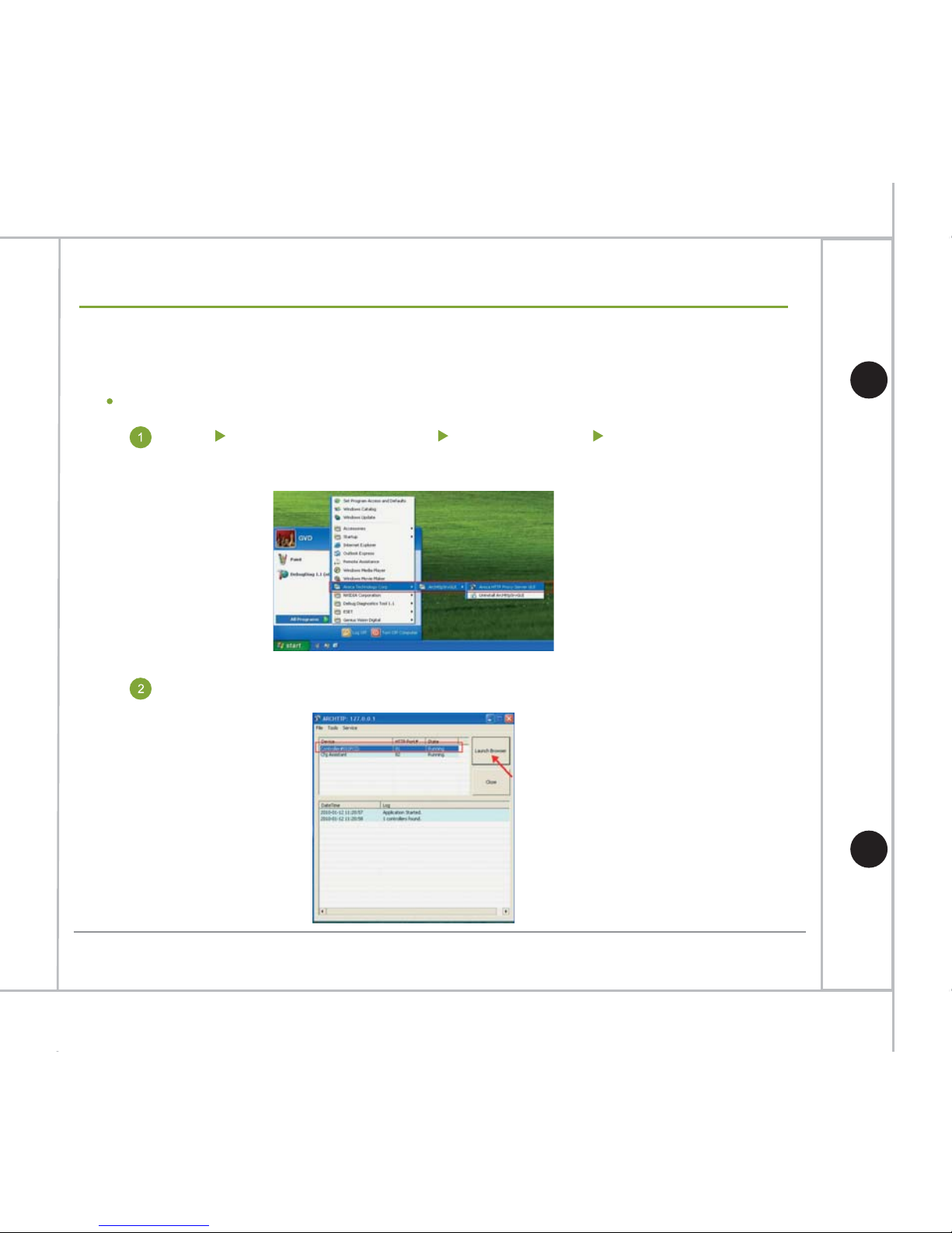
Input admin for username and 0000 for password to login.
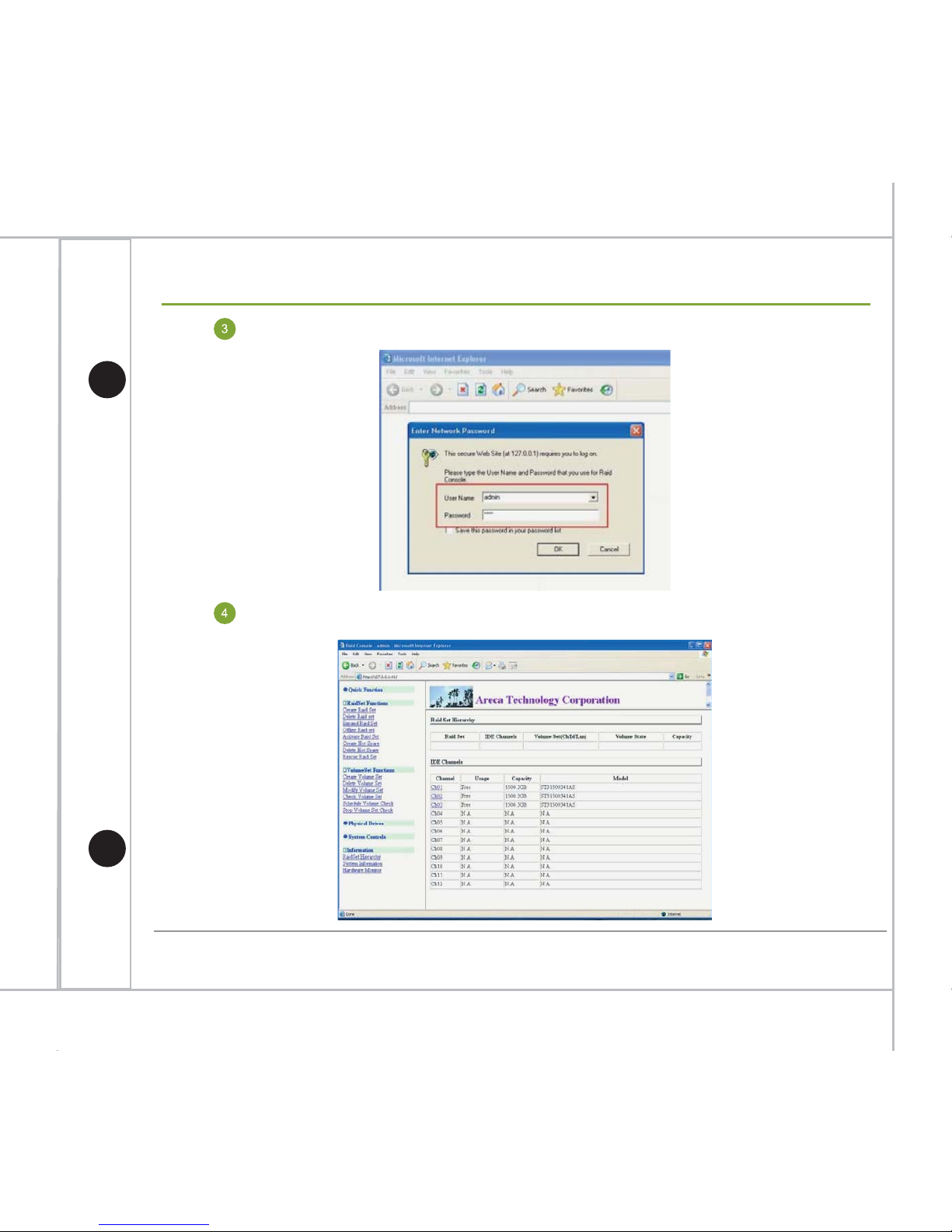
Successfully login to RAID Console page.
Page 29
28
Hardware Quick Installation Guide
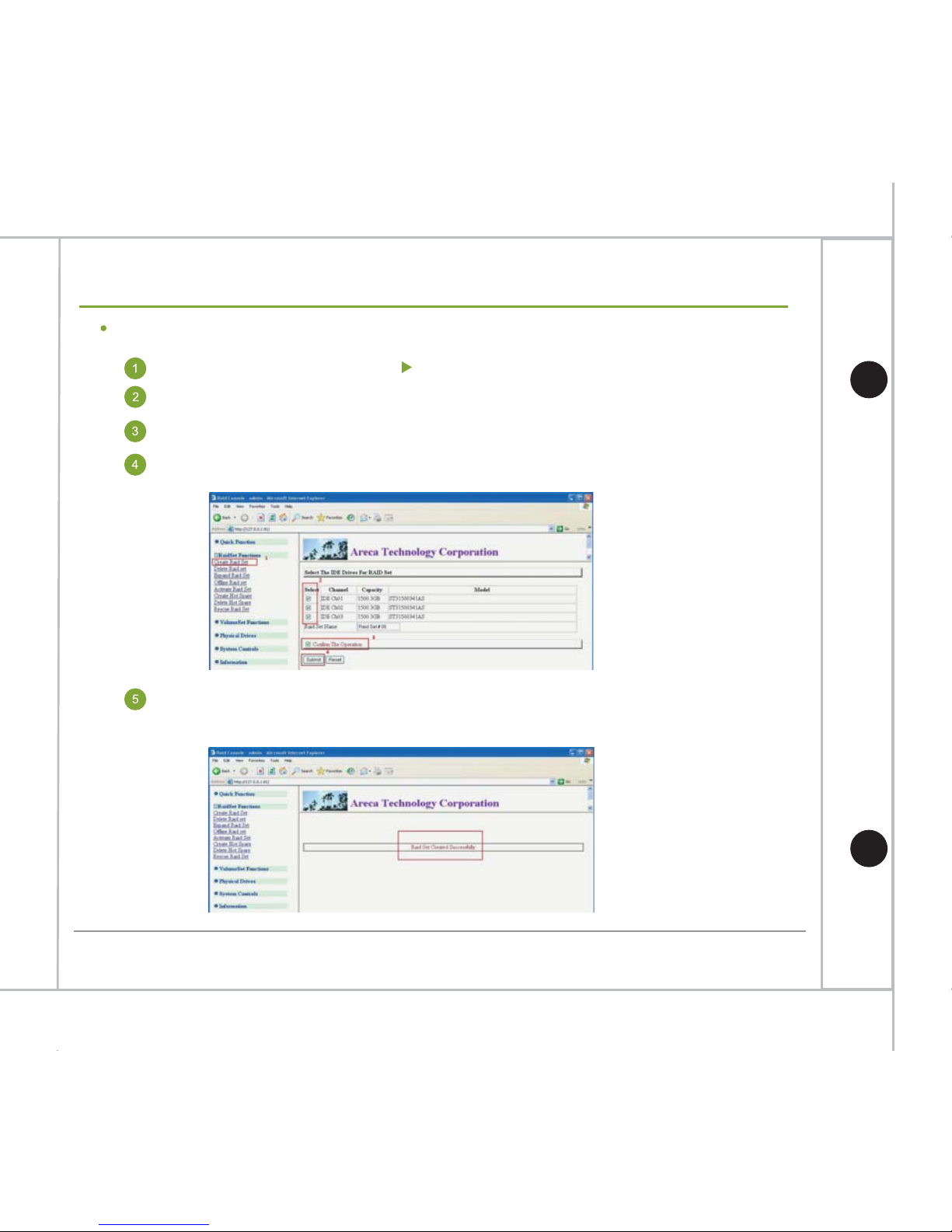
Create RAID Set
Select RaidSet Function Create Raid Set from the menu at the left.
Check the HDDs to be added in the Raid set
(here use 3 HDDs as an example)
Check Confirm The Operation checkbox
Click Submit button to create the Raid set
You should see the following message when the Raid set was created
successfully.
Appendix. How to create RAID 5
Page 30
29
Hardware Quick Installation Guide
Appendix. How to create RAID 5
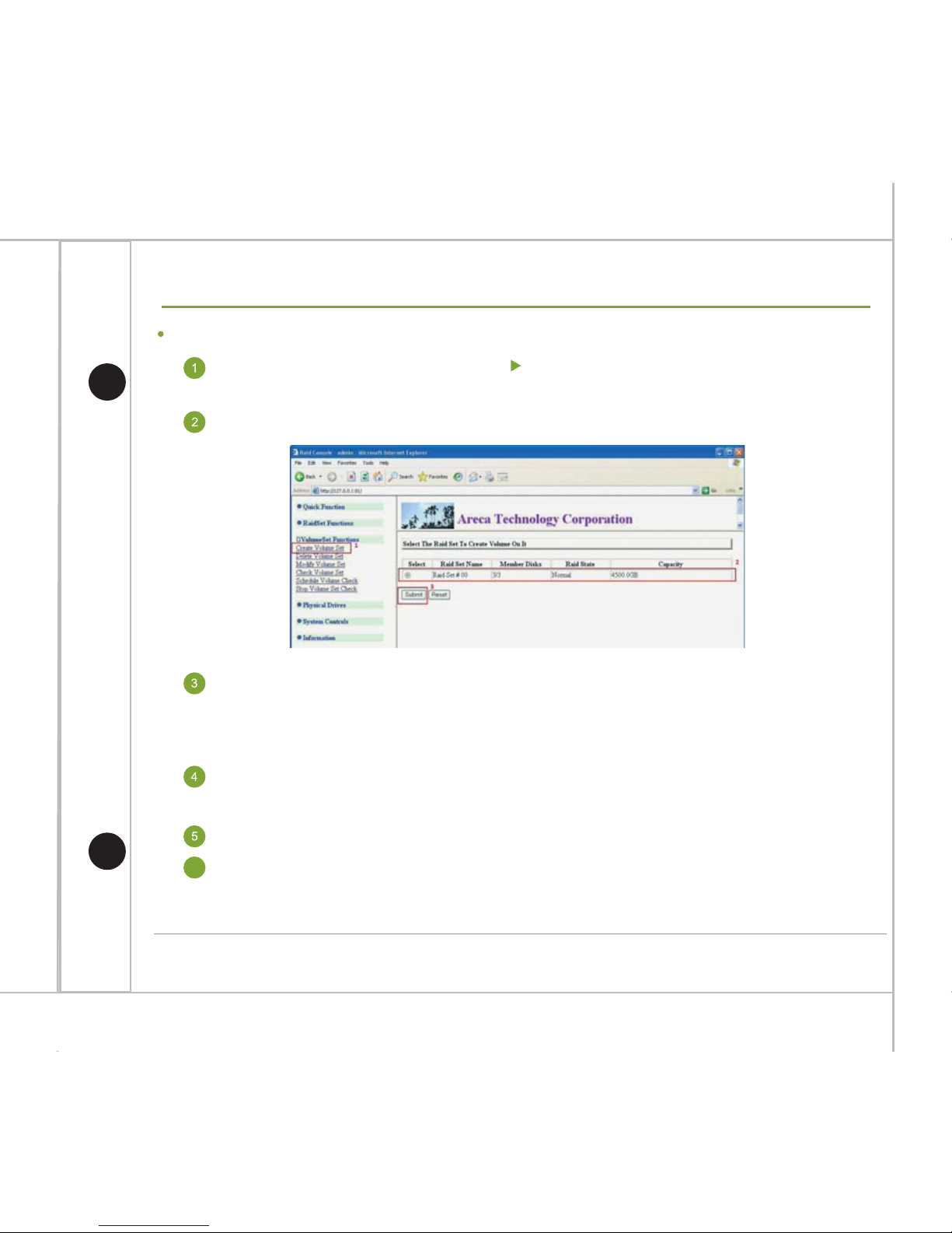
Create Volume Set
Select Volume Set Functions Create Volume Set from the menu at
the left.
Select the Raid set just created and click the Submit button.
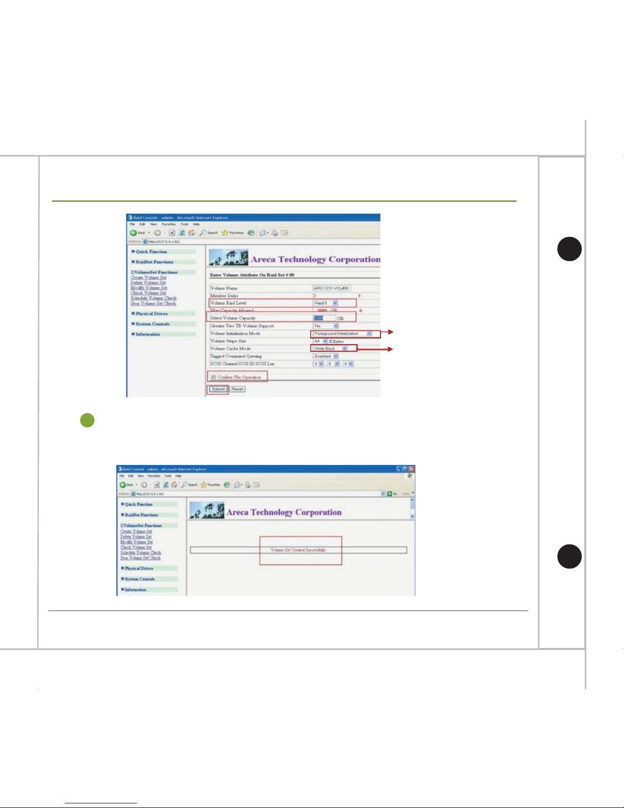
Select the Raid level wish to create (here use Raid 5 as an example).
Input the volume size “1000” each volume to have in Select Volume
Capacity field.
Check Confirm The Operation checkbox.
Click Submit button to create the Raid set
*In Raid 5, when one of the HDDs fails, we can replace it with the new HDD and the system will use
the remaining two HDDs to restore original data. Thus in this example, the total capacity is
1500GB x 2 = 3000GB
*The example just used 3 volumes, each with 1000GB as an example to demonstrate you how to
create a Raid system, you can create different amount of volumes as you wish.
6
Page 31
30
Hardware Quick Installation Guide
You should see the following message when the Volume set was created
successfully.
7
Change to Background Initialization
Change to Write Through
Appendix. How to create RAID 5
Page 32
31
Hardware Quick Installation Guide
Appendix. How to create RAID 5
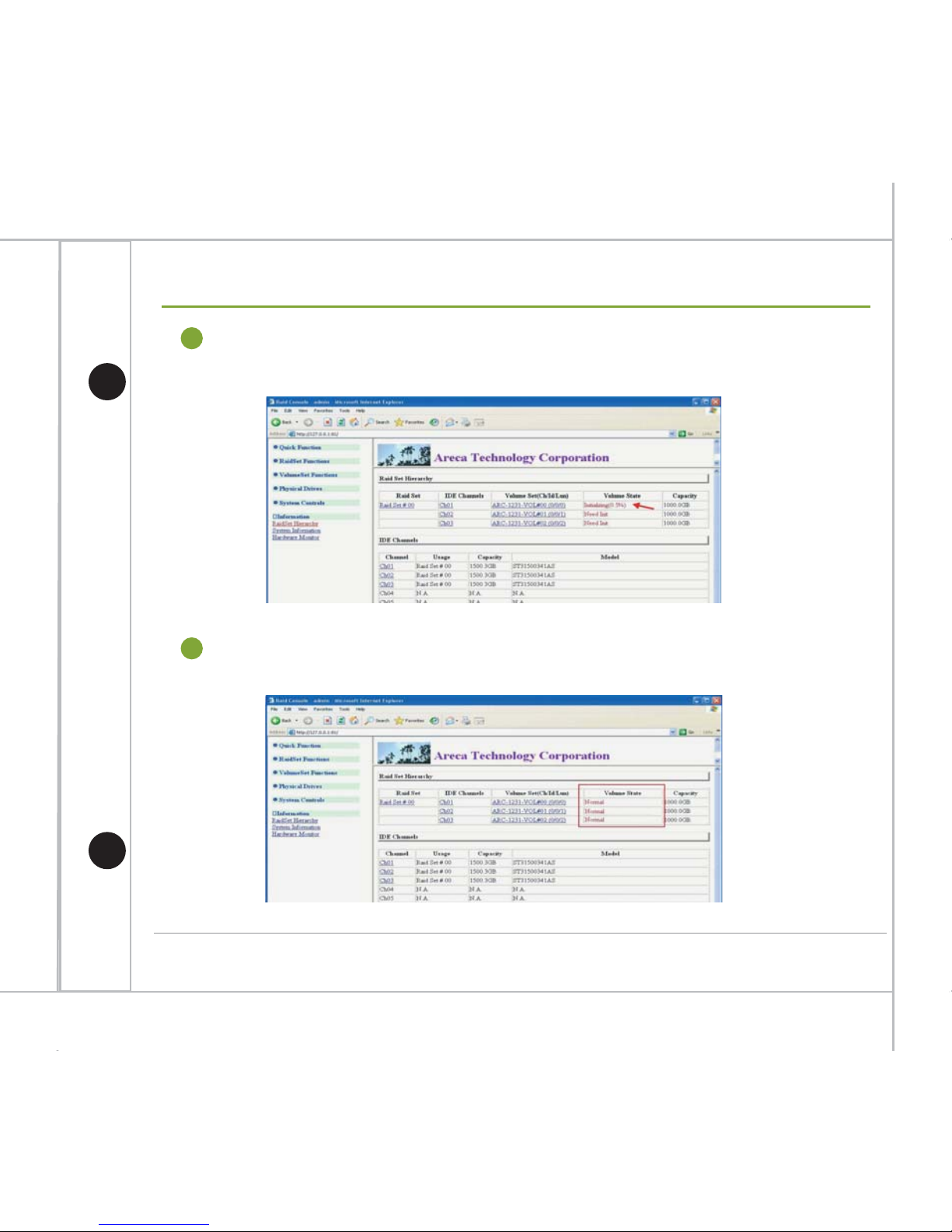
After partition completed, you should see Normal in all Volume State
columns.
9
After volume set was created, it will start to partition the volume set and show
you the completion rate of the process.
8
Page 33
32
Hardware Quick Installation Guide
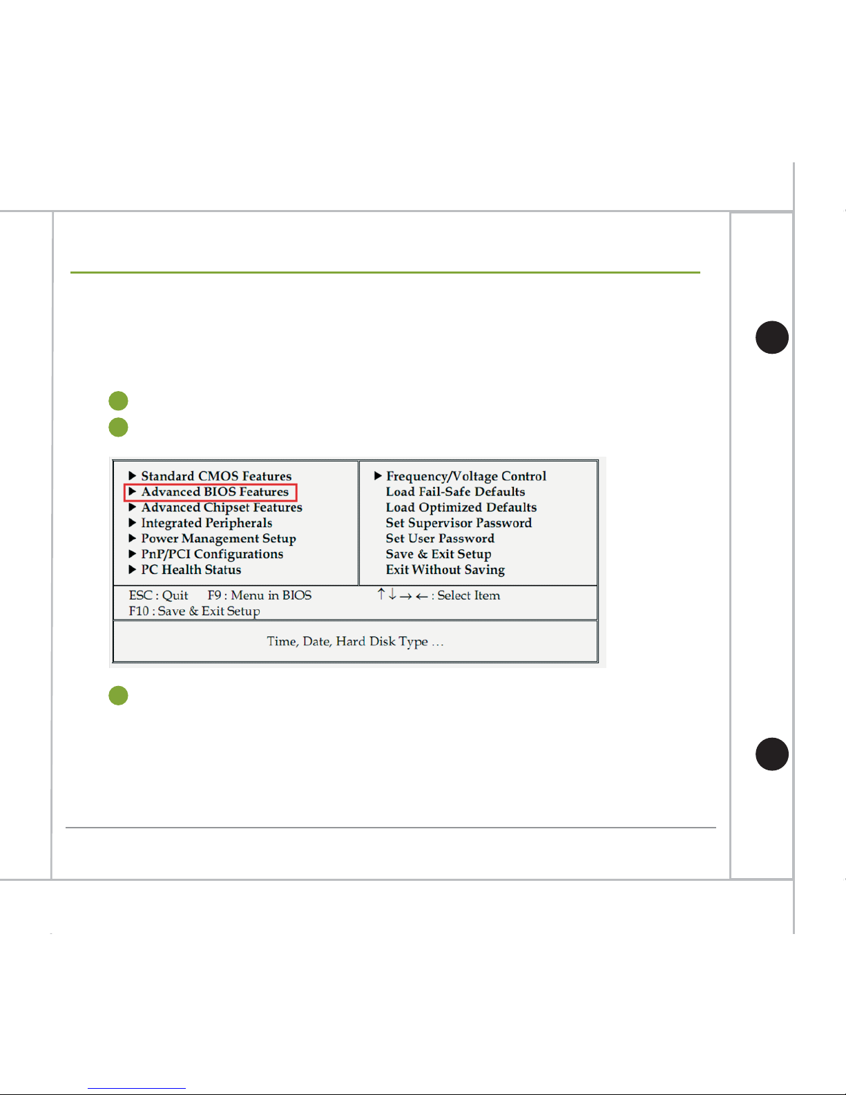
During system boot up, click “Del” key to get into BIOS.
1
Select “Advanced BIOS Features” and press Enter
2
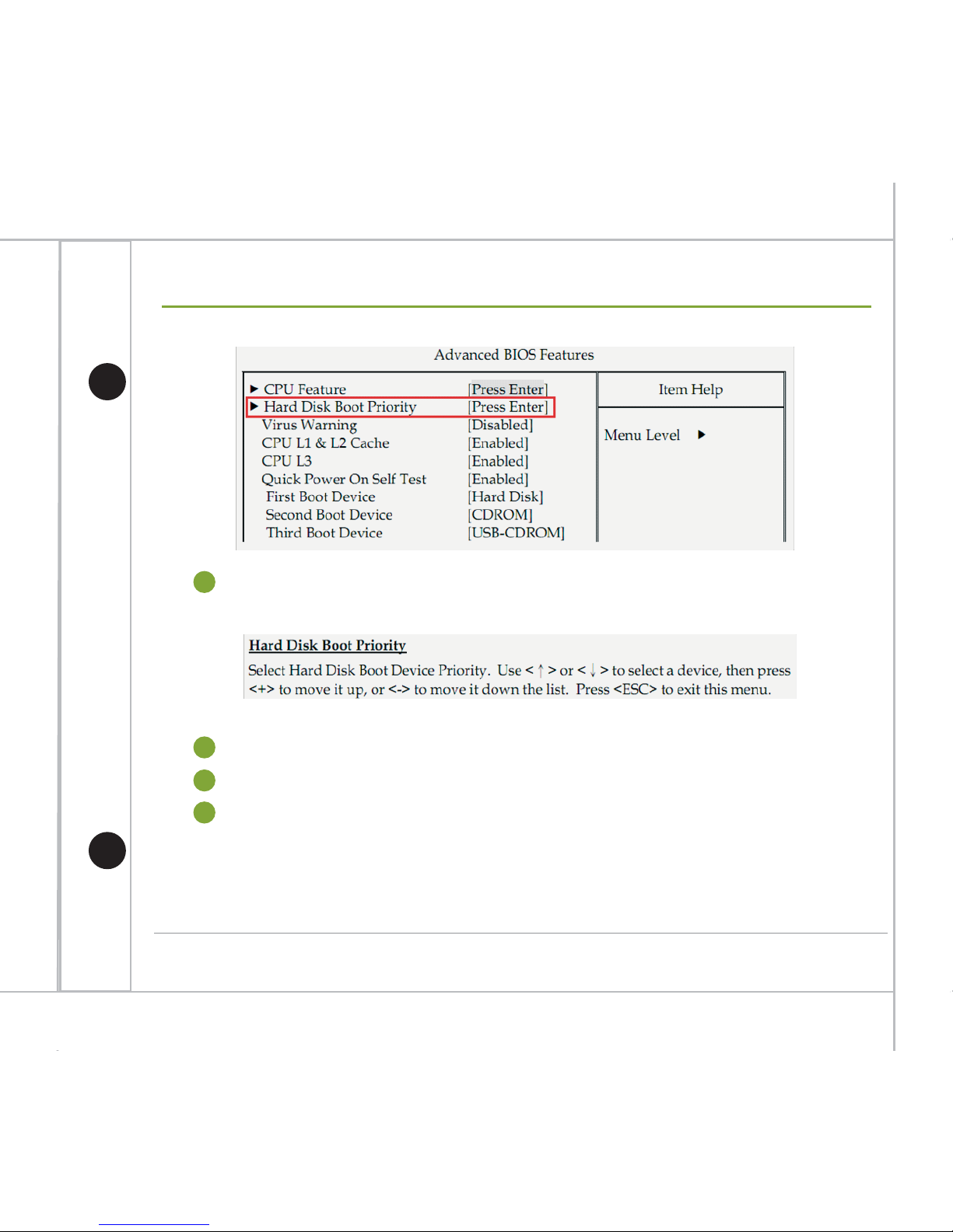
Select “Hard Disk Boot Priority” and press Enter
3
This appendix chapter is for M200-AR only.
Change M200’s boot priority after creating RAID set
Appendix. Change Boot Priority
Page 34
33
Hardware Quick Installation Guide
Appendix. Change Boot Priority
Change the hard disk boot priority and make the DOM device as the first boot device,
e.g. Device name: SATA:PS-4G SATA Flash Drive.
4
Press “ESC” key to return to the main menu.
5
Select “Save & Exit Setup” and press Enter.
6
Answer “Y” to confirm and exit BIOS.
7
Page 35
34
Hardware Quick Installation Guide
1
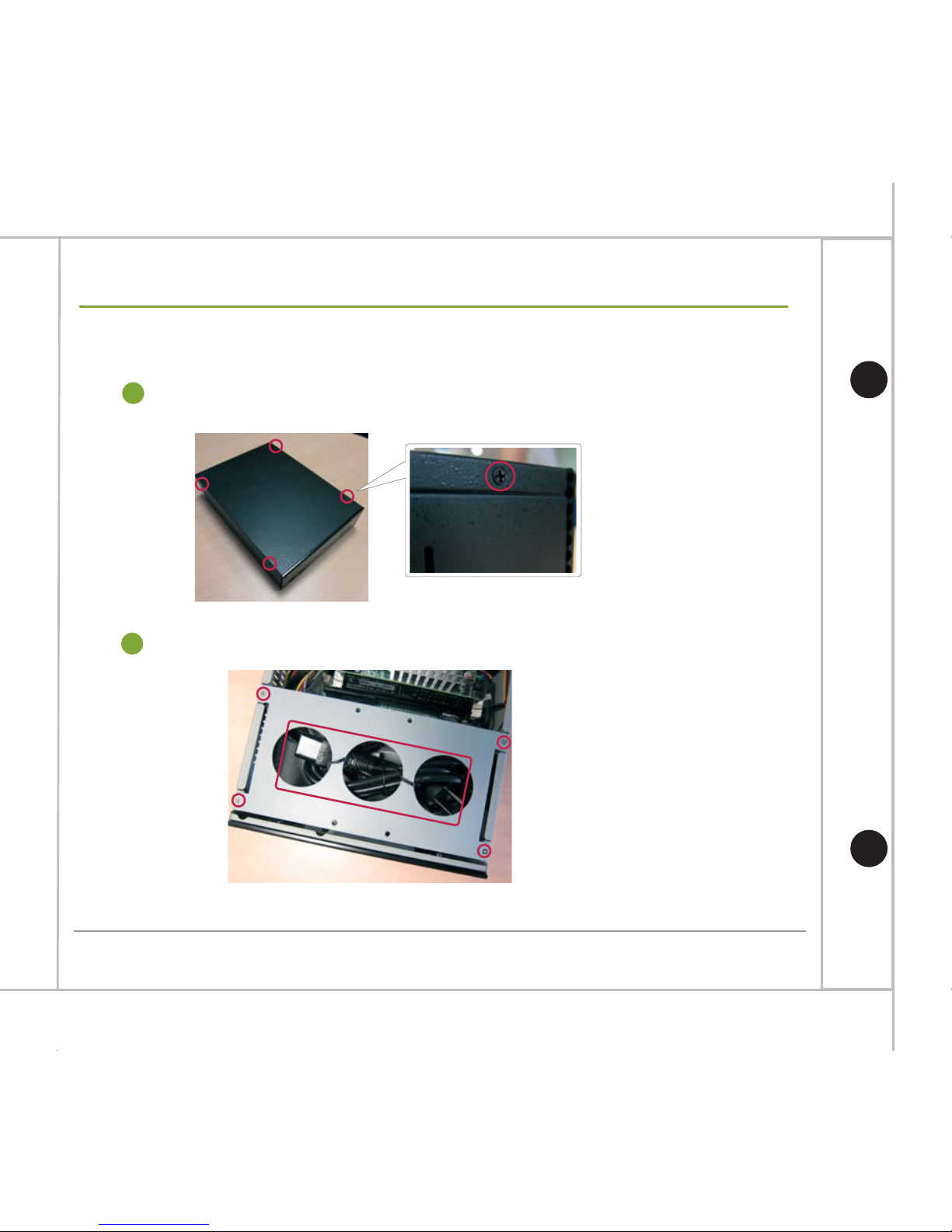
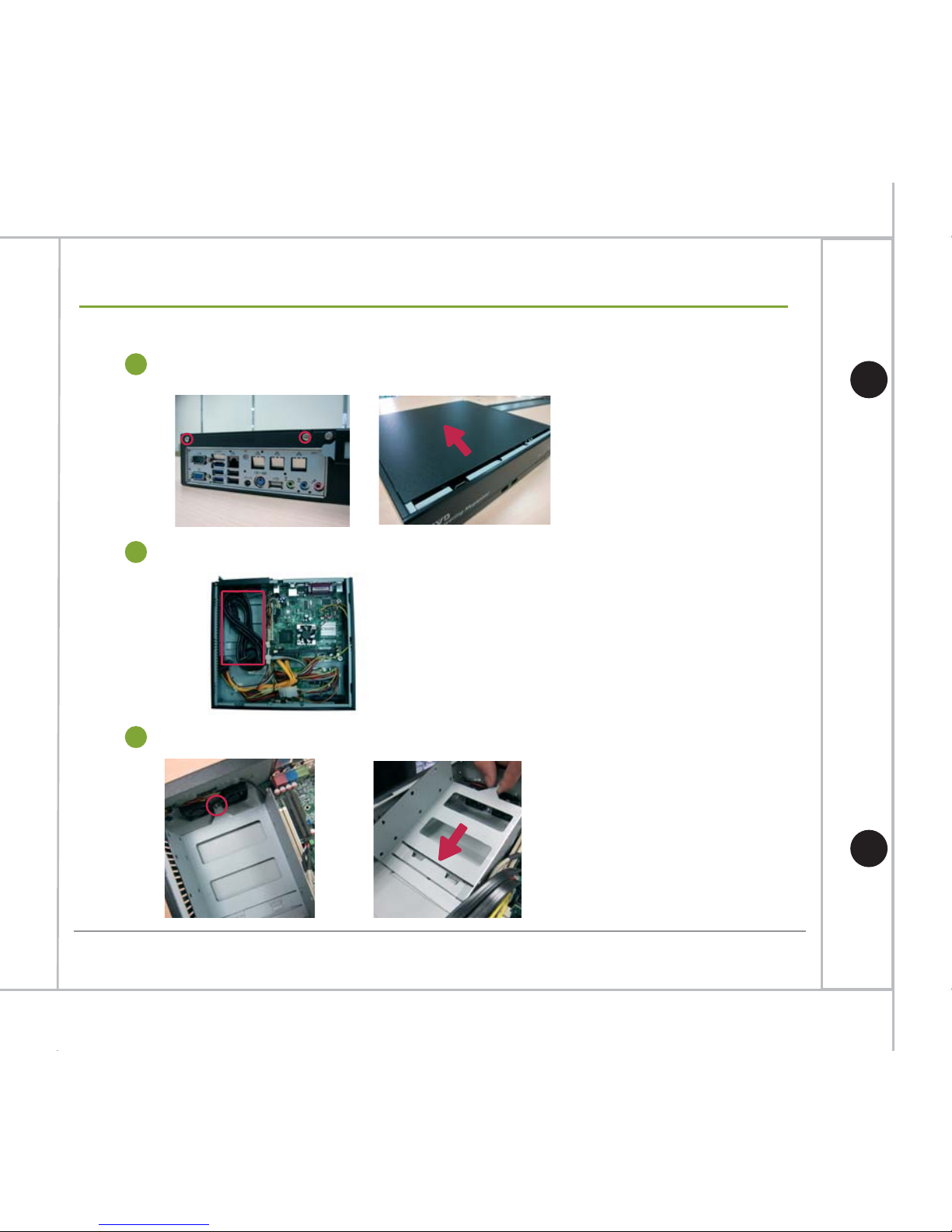
Unscrew the 4 screws to remove the HDD tray and take off the power cord.
2
M90 HDD Installation Guide
Unscrew the screws to remove the machine’s cover as indicated below.
Appendix. HDD Installation Guide
Page 36
35
Hardware Quick Installation Guide
Appendix. HDD Installation Guide
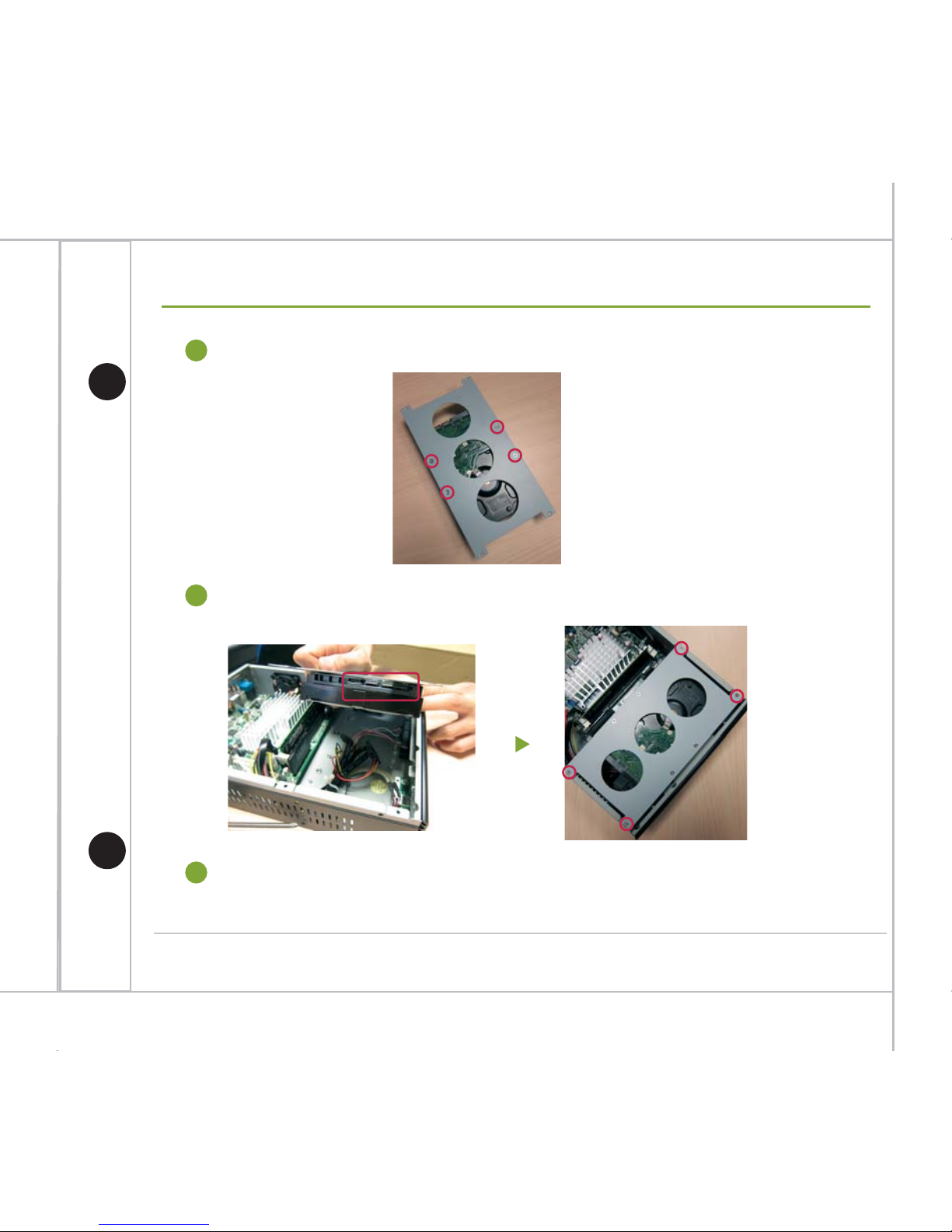
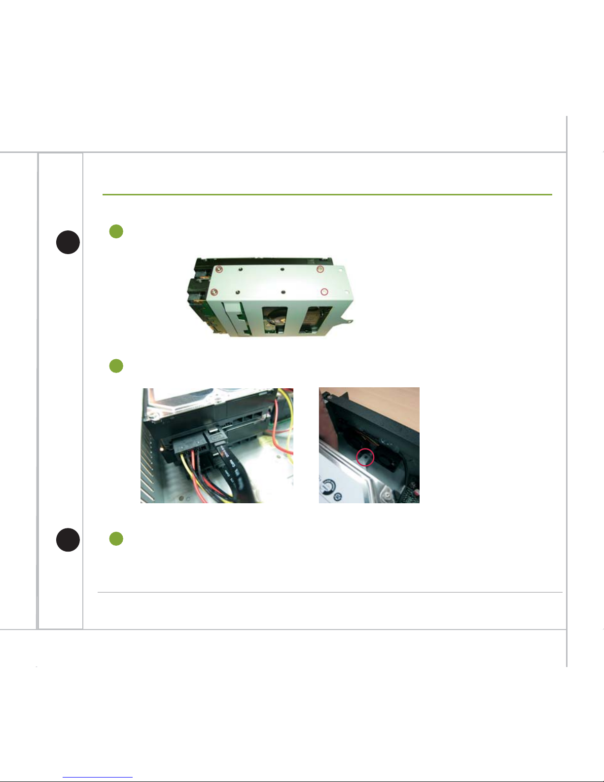
Install HDD to the HDD tray and screw the 4 screws as indicated below.
3
Connect HDD with SATA & power cables then install the HDD tray back to the machine.
4
Install the machine’s cover back.
5
Page 37
Unscrew the screw of the HDD tray and remove it as indicated below.
3
36
Hardware Quick Installation Guide
Unscrew the screws to remove the machine’s cover as indicated below.
1
Take out the power cable as indicated below.
2
M100 HDD Installation Guide
Appendix. HDD Installation Guide
Page 38
37
Hardware Quick Installation Guide
Appendix. HDD Installation Guide
Install HDDs to the HDD tray as indicated below.
4
Connect HDDs with SATA and power cables then install the HDD tray back to the machine.
5
Install the machine’s cover back.
6
Page 39
38
Hardware Quick Installation Guide
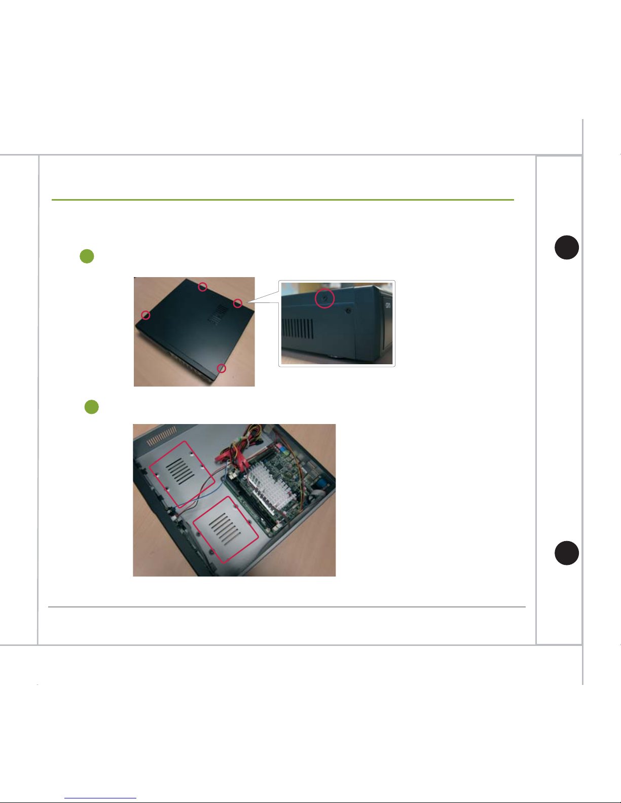
Unscrew the screws to remove the machine’s cover as indicated below.
1
The red rectangles area indicated below is where HDDs will be installed.
2
M150/M155 HDD Installation Guide
Appendix. HDD Installation Guide
Page 40
39
Hardware Quick Installation Guide
Appendix. HDD Installation Guide
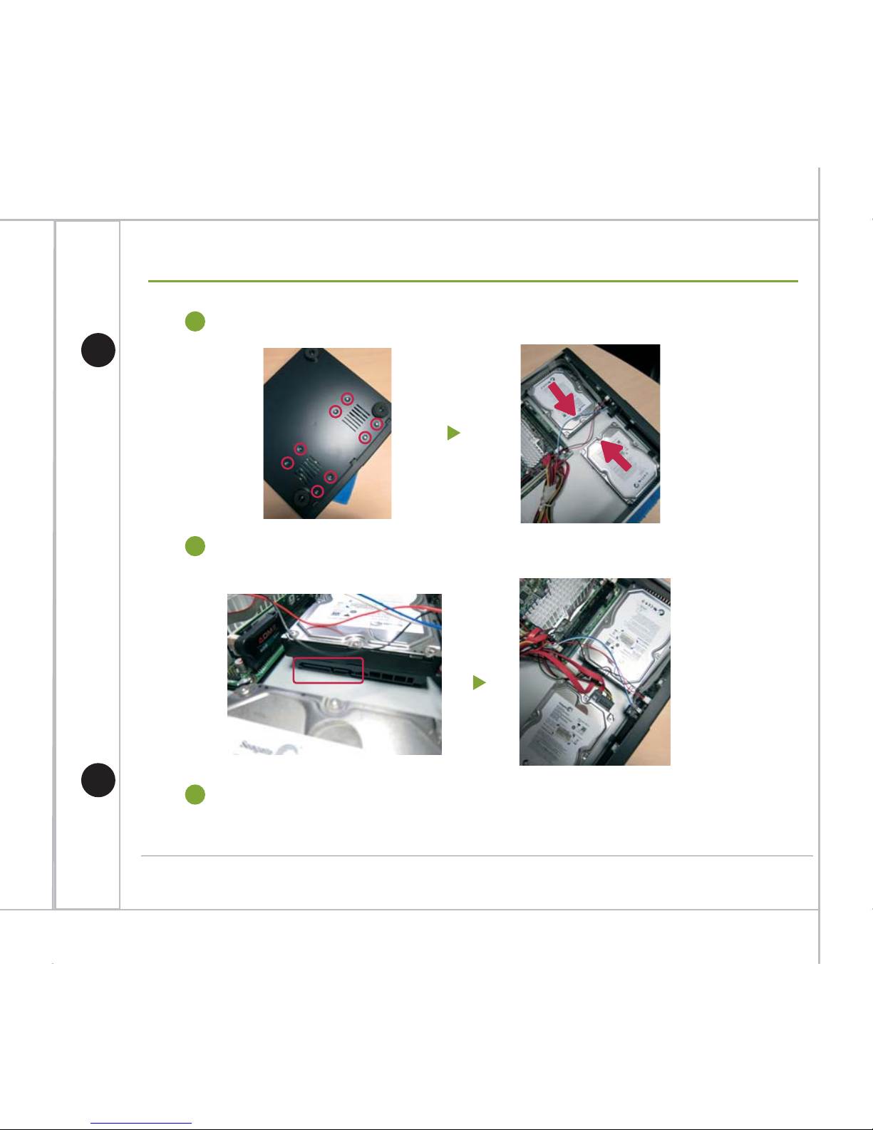
Screw the screws from the bottom side of the case to fix the HDDs.
3
Connect HDDs with SATA & power cables.
4
Install the machine’s cover back.
5
Page 41
40
Hardware Quick Installation Guide
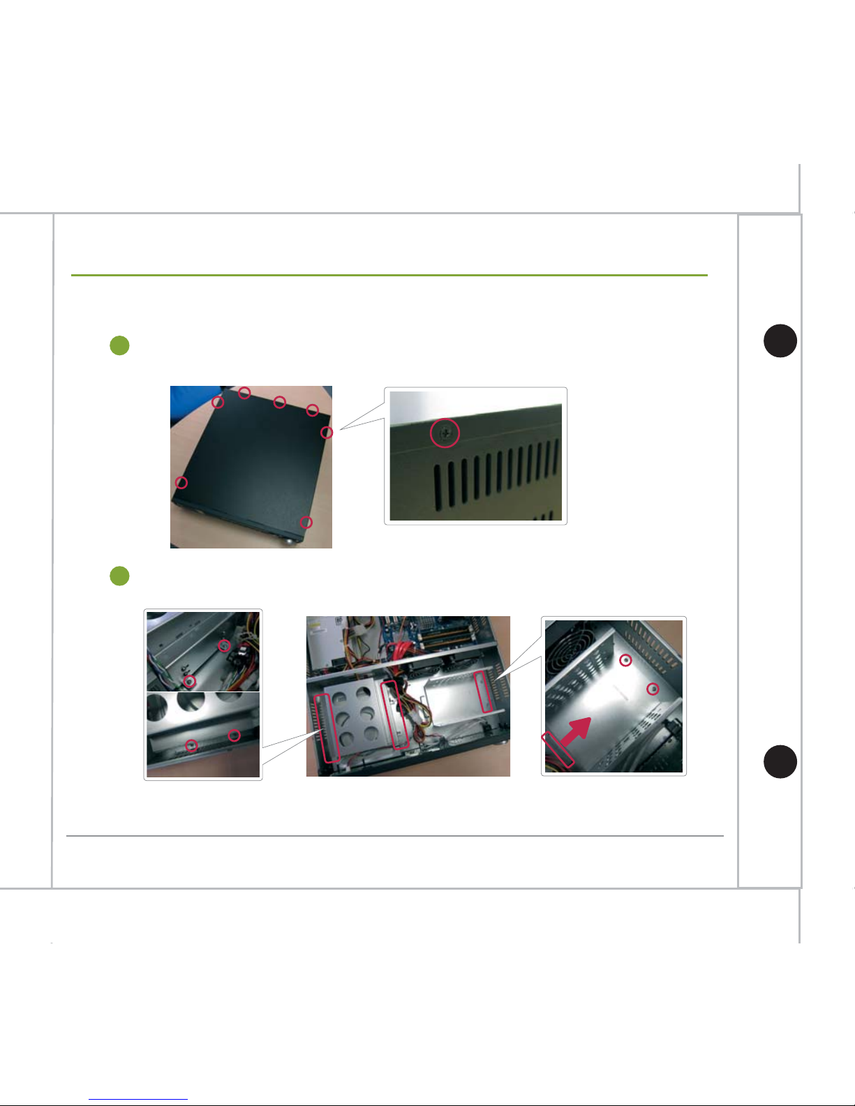
1
Unscrew the screws of CD-ROM & HDD trays as indicated below.
2
M350 HDD Installation Guide
Appendix. HDD Installation Guide
Unscrew the screws to remove the machine’s cover.
(2 screws at each side and 3 at the back, total 7 screws)
Page 42
41
Hardware Quick Installation Guide
Appendix. HDD Installation Guide
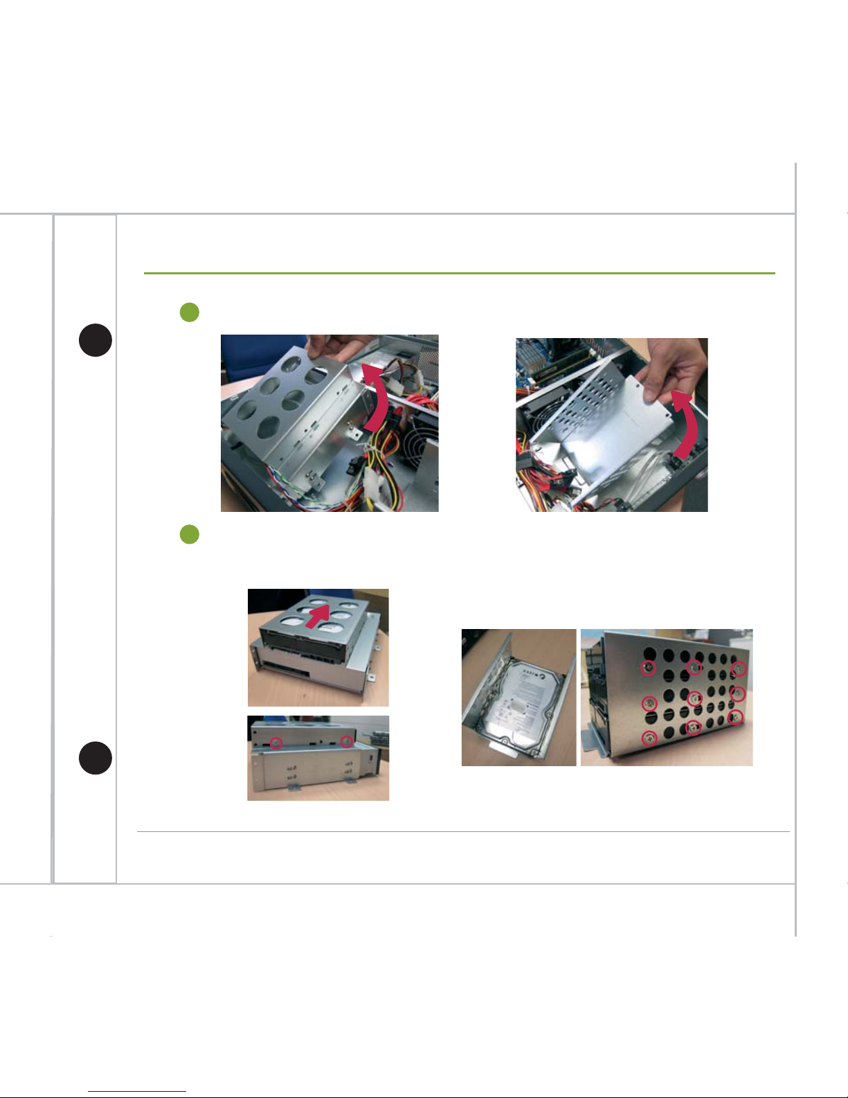
Lift the trays with care.
3
Install HDDs into both CD-ROM & HDD trays and screw the screws to fix the HDDs.
4
CD-ROM Tray
HDD Tray
Page 43
42
Hardware Quick Installation Guide
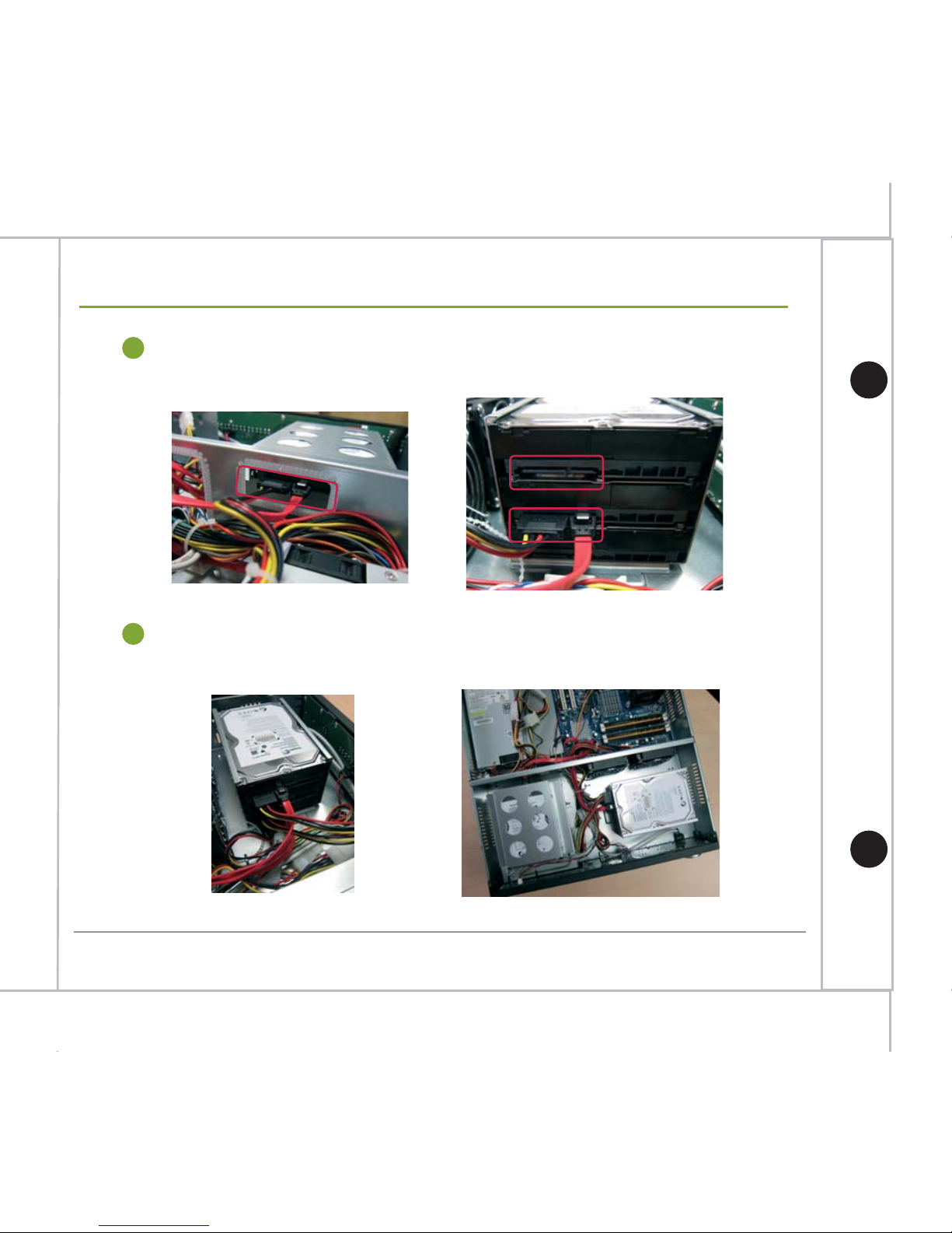
Install both CD-ROM & HDD tray back to the machine and connect both CD-ROM &
HDDs with SATA & power cables.
5
After all HDDs have been installed, it will look like the picture below. Install the
machine’s cover back to finish HDD installation.
6
Appendix. HDD Installation Guide
 Loading...