

GV LDK 400 User Manual

User’s Guide
LDK 400
CAMERA SYSTEM
3922 496 30531
version 1

Declaration of Conformity
We, Thomson Broadcast Solutions B.V., Kapittelweg 10, 4827 HG Breda, The Netherlands, declare under our sole responsibility that this
product is in compliance with the following standards:
EN60065 : Safety
EN55103-1 : EMC (Emission)
EN55103-2 : EMC (Immunity)
following the provisions of:
a. the Safety Directives 73/23//EEC and 93/68/EEC
b. the EMC Directives 89/336/EEC and 93/68/EEC
FCC Class A Statement
This product generates, uses, and can radiate radio frequency energy and if not installed and used in accordance with the instructions,
may cause interference to radio communications.
It has been tested and found to comply with the limits for a class A digital device pursuant to part 15 of the FCC rules, which are
designed to provide reasonable protection against such interference when operated in a commercial environment.
Operation of this product in a residential area is likely to cause interference in which case the user at his own expense will be required to
take whatever measures may be required to correct the interference.
Copyright
Für diese Unterlage behalten wir uns alle
Rechte vor (Gemäß DIN 34). Technische
Änderungen im Zuge der
Weiterentwicklung vorbehalten.
Copying of this document and giving it to
others, and the use or communication of
the contents thereof, are forbidden
without express authority. Offenders are
liable to the payment of damages. All
rights are reserved in the event of the grant
of a patent or the registration of a utility
model or design. Liable to technical
alterations in the course of further
development.
© Copyright Thomson Broadcast and Media Solutions 2005
Toute communication ou reproduction de
ce document, toute exploitation ou
communication de son contenu sont
interdites, sauf autorisation expresse. Tout
man-quement à cette règle est illicite et
expose son auteur au versement de
dommages et intérêts. Tous nos droits sont
réservés pour le cas de la délivrance d'un
modèle d'utilité. Sous réserve de
modification au cours de l'évolution
technique.

LDK 400 User’s Guide iii
Table of Contents
Chapter 1 – Introduction
Technology . . . . . . . . . . . . . . . . . . . . . . . . . . . . . . . . . . . . . . . . . . . . . . . . . . . . . . 1-1
Frame Transfer DPM sensor . . . . . . . . . . . . . . . . . . . . . . . . . . . . . . . . . . . . . . . 1-1
Digital Processing . . . . . . . . . . . . . . . . . . . . . . . . . . . . . . . . . . . . . . . . . . . . . . . 1-2
Film-like characteristics . . . . . . . . . . . . . . . . . . . . . . . . . . . . . . . . . . . . . . . . . . . 1-2
Features . . . . . . . . . . . . . . . . . . . . . . . . . . . . . . . . . . . . . . . . . . . . . . . . . . . . . . . . 1-2
Specifications. . . . . . . . . . . . . . . . . . . . . . . . . . . . . . . . . . . . . . . . . . . . . . . . . . . . . 1-4
Dimensions. . . . . . . . . . . . . . . . . . . . . . . . . . . . . . . . . . . . . . . . . . . . . . . . . . . . 1-7
Accessories . . . . . . . . . . . . . . . . . . . . . . . . . . . . . . . . . . . . . . . . . . . . . . . . . . . . . . 1-8
Chapter 2 – Installation
Packing/unpacking. . . . . . . . . . . . . . . . . . . . . . . . . . . . . . . . . . . . . . . . . . . . . . . . . 2-1
Transport case . . . . . . . . . . . . . . . . . . . . . . . . . . . . . . . . . . . . . . . . . . . . . . . . . . . . 2-2
Mounting a lens . . . . . . . . . . . . . . . . . . . . . . . . . . . . . . . . . . . . . . . . . . . . . . . . . . 2-3
1.5-inch Viewfinder . . . . . . . . . . . . . . . . . . . . . . . . . . . . . . . . . . . . . . . . . . . . . . . . 2-4
Mounting viewfinder and microphone holder . . . . . . . . . . . . . . . . . . . . . . . . . . 2-4
Positioning the viewfinder . . . . . . . . . . . . . . . . . . . . . . . . . . . . . . . . . . . . . . . . 2-5
1.5-inch Viewfinder Accessories. . . . . . . . . . . . . . . . . . . . . . . . . . . . . . . . . . . . . . . 2-5
Wide angle eyepiece. . . . . . . . . . . . . . . . . . . . . . . . . . . . . . . . . . . . . . . . . . . . . 2-5
Left eye adapter . . . . . . . . . . . . . . . . . . . . . . . . . . . . . . . . . . . . . . . . . . . . . . . . 2-6
Mounting a microphone . . . . . . . . . . . . . . . . . . . . . . . . . . . . . . . . . . . . . . . . . . . . 2-7
Tripod adapter plate . . . . . . . . . . . . . . . . . . . . . . . . . . . . . . . . . . . . . . . . . . . . . . . 2-8
Adjusting the shoulder pad . . . . . . . . . . . . . . . . . . . . . . . . . . . . . . . . . . . . . . . . . . 2-9
Mounting a top light . . . . . . . . . . . . . . . . . . . . . . . . . . . . . . . . . . . . . . . . . . . . . . 2-10
Zoom controls . . . . . . . . . . . . . . . . . . . . . . . . . . . . . . . . . . . . . . . . . . . . . . . . . . . 2-11
Attaching an adapter. . . . . . . . . . . . . . . . . . . . . . . . . . . . . . . . . . . . . . . . . . . . . . 2-12
Chapter 3 – Cabling and connectors
Configurations . . . . . . . . . . . . . . . . . . . . . . . . . . . . . . . . . . . . . . . . . . . . . . . . . . . 3-2
Camera with Triax adapter . . . . . . . . . . . . . . . . . . . . . . . . . . . . . . . . . . . . . . . . 3-2
Multiple Triax cameras with C2IP network . . . . . . . . . . . . . . . . . . . . . . . . . . . . 3-2
Camera with Triax adapter and SuperXpander . . . . . . . . . . . . . . . . . . . . . . . . . 3-4
Camera connectors . . . . . . . . . . . . . . . . . . . . . . . . . . . . . . . . . . . . . . . . . . . . . . . . 3-5
Viewfinder connector . . . . . . . . . . . . . . . . . . . . . . . . . . . . . . . . . . . . . . . . . . . . 3-5
Lens connector . . . . . . . . . . . . . . . . . . . . . . . . . . . . . . . . . . . . . . . . . . . . . . . . . 3-6
Audio microphone connector . . . . . . . . . . . . . . . . . . . . . . . . . . . . . . . . . . . . . . 3-6
RS232 serial connector . . . . . . . . . . . . . . . . . . . . . . . . . . . . . . . . . . . . . . . . . . . 3-7

LDK 400 User’s Guide iv
Triax adapter connectors . . . . . . . . . . . . . . . . . . . . . . . . . . . . . . . . . . . . . . . . . . . . 3-8
Triax connector. . . . . . . . . . . . . . . . . . . . . . . . . . . . . . . . . . . . . . . . . . . . . . . . . 3-9
CVBS output connector . . . . . . . . . . . . . . . . . . . . . . . . . . . . . . . . . . . . . . . . . . 3-9
Viewfinder / External video output connector . . . . . . . . . . . . . . . . . . . . . . . . . . 3-9
Script light power supply socket . . . . . . . . . . . . . . . . . . . . . . . . . . . . . . . . . . . 3-10
Teleprompter video output connector. . . . . . . . . . . . . . . . . . . . . . . . . . . . . . . 3-10
DC power and tally output socket. . . . . . . . . . . . . . . . . . . . . . . . . . . . . . . . . . 3-10
Audio microphone 2 connector . . . . . . . . . . . . . . . . . . . . . . . . . . . . . . . . . . . 3-11
DC power input socket . . . . . . . . . . . . . . . . . . . . . . . . . . . . . . . . . . . . . . . . . . 3-11
Audio microphone 1 connector . . . . . . . . . . . . . . . . . . . . . . . . . . . . . . . . . . . 3-12
Intercom headset connector . . . . . . . . . . . . . . . . . . . . . . . . . . . . . . . . . . . . . . 3-12
Reference input connector . . . . . . . . . . . . . . . . . . . . . . . . . . . . . . . . . . . . . . . 3-13
Tracker communications connector. . . . . . . . . . . . . . . . . . . . . . . . . . . . . . . . . 3-13
Auxiliary connector. . . . . . . . . . . . . . . . . . . . . . . . . . . . . . . . . . . . . . . . . . . . . 3-14
Chapter 4 – Operating instructions
Camera head controls . . . . . . . . . . . . . . . . . . . . . . . . . . . . . . . . . . . . . . . . . . . . . . 4-3
Viewfinder controls . . . . . . . . . . . . . . . . . . . . . . . . . . . . . . . . . . . . . . . . . . . . . . . . 4-4
Assigning functions to buttons . . . . . . . . . . . . . . . . . . . . . . . . . . . . . . . . . . . . . 4-5
Using the camera. . . . . . . . . . . . . . . . . . . . . . . . . . . . . . . . . . . . . . . . . . . . . . . . . . 4-6
Switching on the power . . . . . . . . . . . . . . . . . . . . . . . . . . . . . . . . . . . . . . . . . . 4-6
Controlling the camera . . . . . . . . . . . . . . . . . . . . . . . . . . . . . . . . . . . . . . . . . . . 4-6
Access and Security . . . . . . . . . . . . . . . . . . . . . . . . . . . . . . . . . . . . . . . . . . . . . . . . 4-7
Camera cards . . . . . . . . . . . . . . . . . . . . . . . . . . . . . . . . . . . . . . . . . . . . . . . . . . 4-7
Access control . . . . . . . . . . . . . . . . . . . . . . . . . . . . . . . . . . . . . . . . . . . . . . . . . 4-8
Camera card slot . . . . . . . . . . . . . . . . . . . . . . . . . . . . . . . . . . . . . . . . . . . . . . . 4-8
System Menu. . . . . . . . . . . . . . . . . . . . . . . . . . . . . . . . . . . . . . . . . . . . . . . . . . . . . 4-9
Entering the System menu . . . . . . . . . . . . . . . . . . . . . . . . . . . . . . . . . . . . . . . . 4-9
Finding your way . . . . . . . . . . . . . . . . . . . . . . . . . . . . . . . . . . . . . . . . . . . . . . 4-10
Leaving the System Menu . . . . . . . . . . . . . . . . . . . . . . . . . . . . . . . . . . . . . . . . 4-10
Making changes . . . . . . . . . . . . . . . . . . . . . . . . . . . . . . . . . . . . . . . . . . . . . . . 4-11
Undoing changes . . . . . . . . . . . . . . . . . . . . . . . . . . . . . . . . . . . . . . . . . . . . . . 4-11
Viewfinder preferences . . . . . . . . . . . . . . . . . . . . . . . . . . . . . . . . . . . . . . . . . . . . 4-12
Viewfinder picture quality . . . . . . . . . . . . . . . . . . . . . . . . . . . . . . . . . . . . . . . . 4-12
Video level indication . . . . . . . . . . . . . . . . . . . . . . . . . . . . . . . . . . . . . . . . . . . 4-12
Tally indicators . . . . . . . . . . . . . . . . . . . . . . . . . . . . . . . . . . . . . . . . . . . . . . . . 4-12
Viewfinder markers. . . . . . . . . . . . . . . . . . . . . . . . . . . . . . . . . . . . . . . . . . . . . 4-12
Lens preferences . . . . . . . . . . . . . . . . . . . . . . . . . . . . . . . . . . . . . . . . . . . . . . . . . 4-13
Lens type . . . . . . . . . . . . . . . . . . . . . . . . . . . . . . . . . . . . . . . . . . . . . . . . . . . . 4-13
Auto iris . . . . . . . . . . . . . . . . . . . . . . . . . . . . . . . . . . . . . . . . . . . . . . . . . . . . . 4-13
Extended Iris . . . . . . . . . . . . . . . . . . . . . . . . . . . . . . . . . . . . . . . . . . . . . . . . . . 4-13
Lens indicators . . . . . . . . . . . . . . . . . . . . . . . . . . . . . . . . . . . . . . . . . . . . . . . . 4-13

LDK 400 User’s Guide v
Video preferences . . . . . . . . . . . . . . . . . . . . . . . . . . . . . . . . . . . . . . . . . . . . . . . . 4-14
Standard settings . . . . . . . . . . . . . . . . . . . . . . . . . . . . . . . . . . . . . . . . . . . . . . 4-14
Test signal . . . . . . . . . . . . . . . . . . . . . . . . . . . . . . . . . . . . . . . . . . . . . . . . . . . 4-14
Studio mode selection . . . . . . . . . . . . . . . . . . . . . . . . . . . . . . . . . . . . . . . . . . 4-15
Gain selection. . . . . . . . . . . . . . . . . . . . . . . . . . . . . . . . . . . . . . . . . . . . . . . . . 4-15
Optical filter selection . . . . . . . . . . . . . . . . . . . . . . . . . . . . . . . . . . . . . . . . . . . 4-16
Colour temperature selection . . . . . . . . . . . . . . . . . . . . . . . . . . . . . . . . . . . . . 4-16
Exposure time. . . . . . . . . . . . . . . . . . . . . . . . . . . . . . . . . . . . . . . . . . . . . . . . . 4-19
Black stretch. . . . . . . . . . . . . . . . . . . . . . . . . . . . . . . . . . . . . . . . . . . . . . . . . . 4-21
Auto skin contour. . . . . . . . . . . . . . . . . . . . . . . . . . . . . . . . . . . . . . . . . . . . . . 4-21
Classic mode . . . . . . . . . . . . . . . . . . . . . . . . . . . . . . . . . . . . . . . . . . . . . . . . . 4-23
Managing files. . . . . . . . . . . . . . . . . . . . . . . . . . . . . . . . . . . . . . . . . . . . . . . . . . . 4-24
Scene files . . . . . . . . . . . . . . . . . . . . . . . . . . . . . . . . . . . . . . . . . . . . . . . . . . . 4-24
Operator files . . . . . . . . . . . . . . . . . . . . . . . . . . . . . . . . . . . . . . . . . . . . . . . . . 4-24
Standard files . . . . . . . . . . . . . . . . . . . . . . . . . . . . . . . . . . . . . . . . . . . . . . . . . 4-25
Customer standard files . . . . . . . . . . . . . . . . . . . . . . . . . . . . . . . . . . . . . . . . . 4-25
User levels . . . . . . . . . . . . . . . . . . . . . . . . . . . . . . . . . . . . . . . . . . . . . . . . . . . . . . 4-26
Selecting the user level . . . . . . . . . . . . . . . . . . . . . . . . . . . . . . . . . . . . . . . . . . 4-26
Smart-Touch™ . . . . . . . . . . . . . . . . . . . . . . . . . . . . . . . . . . . . . . . . . . . . . . . . . . 4-27
Triax adapter controls . . . . . . . . . . . . . . . . . . . . . . . . . . . . . . . . . . . . . . . . . . . . . 4-28
Powering the camera . . . . . . . . . . . . . . . . . . . . . . . . . . . . . . . . . . . . . . . . . . . 4-29
Selecting monitoring signals . . . . . . . . . . . . . . . . . . . . . . . . . . . . . . . . . . . . . . 4-29
Using audio . . . . . . . . . . . . . . . . . . . . . . . . . . . . . . . . . . . . . . . . . . . . . . . . . . 4-29
Intercom. . . . . . . . . . . . . . . . . . . . . . . . . . . . . . . . . . . . . . . . . . . . . . . . . . . . . 4-30
Communication . . . . . . . . . . . . . . . . . . . . . . . . . . . . . . . . . . . . . . . . . . . . . . . 4-31
Chapter 5 – Menu structure
Menu structure . . . . . . . . . . . . . . . . . . . . . . . . . . . . . . . . . . . . . . . . . . . . . . . . . . . 5-2
Main (top) menu . . . . . . . . . . . . . . . . . . . . . . . . . . . . . . . . . . . . . . . . . . . . . . . 5-2
Where to find a function . . . . . . . . . . . . . . . . . . . . . . . . . . . . . . . . . . . . . . . . . 5-6

LDK 400 User’s Guide vi

Important information vii
Important information
Read these instructions carefully and retain them for future reference.
During installation and operation of this equipment, local building safety and fire
protection standards must be observed.
Before connecting the equipment to the power supply of the installation, verify the
proper functioning of the protective earth lead.
Whenever it is likely that safe operation is impaired, the apparatus must be made
inoperative and secured against any unintended operation. The appropriate servicing
authority must then be informed. For example, safety is likely to be impaired if the
apparatus fails to perform the intended function or shows visible damage.
Any changes or modifications not expressly approved in this manual could void your
authority to operate this equipment.
Cautions and Warnings
Read and comply with the warning and caution notices that appear in the manual.
• Warnings indicate danger that requires correct procedures or practices to
prevent death or injury to personnel.
• Cautions indicate procedures or practices that should be followed to prevent
damage or destruction to equipment or property.

Important information viii
Warnings
WARNING
To prevent fire or shock hazard, do not expose the unit to rain or moisture. If the unit
is in a wet or damp environment, a rain cover must be used to protect it for personal
safety reasons (EN60065). The rain cover supplied with the unit protects it according to
safety specification EN60529 up to level IPX2 (spraying water).
To avoid electrical shock, do not remove covers or panels. Refer servicing to qualified
personnel only.
In case of an emergency ensure that the power is disconnected.
Use only fuses of the type and rating specified.
Connect the product only to a power source with the specified voltage rating.
The Base Station must always be connected to protective earth. Do not interrupt the
protection conductor inside or outside the unit. Do not disconnect the protective earth
terminal. Intentional interruption is prohibited and is likely to make the unit dangerous.
To prevent risk of overheating, ventilate the units correctly.
For safety reasons the Base Station must be mounted in a 19-inch rack which has
safety covers according to IEC65. When two Base Stations are mounted above each
other, the minimum distance between them must be 50mm or the rack must be forceair cooled.
Triax cable systems
WARNING
Only connect a Triax cable from the same LDK camera family to the unit.
Do not allow system ground currents to exceed 1.5A in the outer shield of the Triax
cable or 0.2A in other cable shields.
It is strickly prohibited to short circuit the inner and outer shields of a Triax cable used
to connect a camera to a base station.
Important information ix
Fibre optic transmission units
CLASS 1
LASER PRODUCT
LASER KLASSE 1
PRODUKT
The CLASS 1 LASER PRODUCT label is located on top of the fibre optic connector on
the rear panel.
Laser safety statement (Europe)
Fibre optic transmission units are classified as a "CLASS 1 Laser Product" according to
EN 60825-1, Safety of Laser products. Class 1 laser products are considered safe and
do not result in biological hazard if used according to the instructions.
Laser safety statement (US)
Fibre optic transmission units are classified as a "CLASS 1 Laser Product" according to
21CFR 1040.10 of the US Food and Drug Administration (FDA) Center for Devices and
Radiological Health.
WARNING
Use of controls, adjustments or performance of procedures other than those specified
herein may result in hazardous radiation exposure.
To ensure proper use of this product, please read this instruction manual carefully and
retain for future reference. Should the unit ever require maintenance, contact an
authorized service location.

Important information x
Mains lead wiring for UK users
The wires in the mains lead are coloured in accordance with the following code:
GREEN and YELLOW- EARTH
BLUE - NEUTRAL
BROWN - LIVE
As the colours of the wires in the mains lead of this apparatus may not correspond
with the coloured markings identifying the terminals in your plug proceed as follows:
• The wire coloured GREEN AND YELLOW must be connected to the terminal on the
plug marked with the letter E or by the safety earth symbol
or coloured GREEN
or GREEN AND YELLOW.
• The wire coloured BROWN must be connected to the terminal marked with the
letter L or coloured RED.
• The wire coloured BLUE must be connected to the terminal marked with the letter
N or coloured BLACK.
Ensure that your equipment is connected correctly - if you are in any doubt consult a
qualified electrician.

Important information xi
Precautions
To ensure continual high performance from the camera take the following precautions
into consideration:
• Avoid very damp places. If the environment is wet or damp a rain cover must be
used to protect the unit.
• Do not subject the unit to severe shocks or vibration.
• Do not expose the camera to extremes of temperature.
• Do not leave the unit in direct sunlight or close to heating appliances for extended
periods.
• Do not allow sunlight to shine into the viewfinder.
• Do not allow LASER beams to shine into the lens as this could damage the CCD
sensors.
• Avoid extreme highlights as these can cause various kinds of optical reflections.
• Be careful when connecting and disconnecting triax cables.
- Do not mix triax units from different types of camera systems (HD with SD, RGB
triax with digital triax).
- Make connections swiftly and firmly to avoid false error messages.
• In fibre optic cable systems always put the dust caps on cable and panel connectors
immediately after disconnecting a cable. Keep the dust caps clean.

Important information xii
Base Station earthing
The rear of the unit has two separate screw terminals for protective earth (PE) and
video earth (VE). These are normally connected by a metal strap.
Metal strap
VE
PE
The protective earth terminal is internally connected to the protective earth conductor
of the power cable. In normal circumstances the connection between the protective
earth and the video earth should not be broken. If required, the central earth
connection wire of the studio can be connected to terminal PE.
Only if the studio (or OB van) is equipped with separate protective and video earth
systems may the metal strap be removed. Under these circumstances the video earth
terminal must be connected to the central functional earth potential (video earth) of
the studio. This earth potential should have functional protective and noiseless earth
(FPE) qualities as stated in the VDE regulation 0800/part2. A low impedance
interconnection of both earth conductors must be provided at the central studio
earthing point.

Introduction 1-1
Chapter 1
Introduction
This section outlines the technology used in the camera system and describes how this
translates into a practical, useable camera. It lists the main features of the camera.
Contents
Technology . . . . . . . . . . . . . . . . . . . . . . . . . . . . . . . . . . . . . . . . . . . . . . . . . . . . . . 1-1
Frame Transfer DPM sensor . . . . . . . . . . . . . . . . . . . . . . . . . . . . . . . . . . . . . . . 1-1
Digital Processing . . . . . . . . . . . . . . . . . . . . . . . . . . . . . . . . . . . . . . . . . . . . . . . 1-2
Film-like characteristics . . . . . . . . . . . . . . . . . . . . . . . . . . . . . . . . . . . . . . . . . . . 1-2
Features . . . . . . . . . . . . . . . . . . . . . . . . . . . . . . . . . . . . . . . . . . . . . . . . . . . . . . . . 1-2
Specifications. . . . . . . . . . . . . . . . . . . . . . . . . . . . . . . . . . . . . . . . . . . . . . . . . . . . . 1-4
Dimensions. . . . . . . . . . . . . . . . . . . . . . . . . . . . . . . . . . . . . . . . . . . . . . . . . . . . 1-7
Accessories . . . . . . . . . . . . . . . . . . . . . . . . . . . . . . . . . . . . . . . . . . . . . . . . . . . . . . 1-8
1.1 Technology
The camera head uses three 2/3-inch CCD sensors. It is available with DPM, FT, IT or
ITW type sensors. A range of adapters can be connected to the head making a flexible
camera system that is equally at home in the studio or out on location in an OB
environment.
1.1.1 Frame Transfer DPM sensor
The Frame Transfer CCD DPM sensor offers superior performance and can handle
highlights of up to 600%. The 2/3-inch sensors have a high dynamic range and high
linear sensitivity over all camera lens apertures. Frame Transfer technology ensures that
there is no lag nor smear. The Frame Transfer DPM sensor uses Dynamic Pixel
Management which allows the format of the sensors to be switched between 4:3 and
16:9 aspect ratios at the touch of a switch without loss of horizontal or vertical
resolution. The 1000 pixels per line in both formats ensures that there is no loss in the
horizontal viewing angle but also ensures high resolution in the red, green and blue
channels.

Introduction | Features 1-2
1.1.2 Digital Processing
The advanced digital processing of the camera is based on 14-bit A/D converters and
more than 22-bit internal processing. Two DSPs combine all major camera functions in
the digital domain, including knee, gamma, contour, matrix and colour correction.
The intelligent continuous automatics facility provides automatic control of black levels
and black shading. Each sensor provides black reference signals that are used to
monitor temperature changes. This means that continuous automatic correction is
applied without operator intervention.
The digital contour processing uses full amplitude video RGB signals via an extended
dynamic range contour circuit.
A special Studio Mode provides the opportunity for capturing even higher quality
images with outstanding signal-to-noise ratios. This mode is especially useful in
environments where light levels and dynamic range are well controlled.
Colorimetry is selected by means of a variable 6-point digital matrix or via preset
matrices. Digital gamma circuits provide a wide range of standardised gamma curves
and enable soft contrast in black scenes to be enhanced, together with hard contrast
and saturated colour in bright scenes. The matrix and gamma sequence is software
programmable for precise colour matching.
1.1.3 Film-like characteristics
The pivoting knee circuit adapts both the knee point and the compression ratio
according to the highlight content of the picture to emulate the softly limiting
S-shaped transfer characteristics of film. Digital True Colour Knee circuitry maintains
the correct hue for compressed highlights, reproducing colours faithfully, even
overexposed skin tones.
Digital contrast circuitry provides a black stretch function for more detail in black areas
and a black press function for improving the contrast impression by simulating the
S-curve of film.
1.2 Features
• Three 2/3-inch switchable DPM FT sensors ensure no vertical smear.
• DPM Frame Transfer sensors with 1000 horizontal pixels in 4:3 and 16:9 aspect
ratios, and the same number of vertical lines in both formats. No change in
horizontal viewing angle - so no optical wide angle convertors required.
• 14-bit digital processing with unique software programmable video path.
• Excellent signal-to-noise ratio (typically 65 dB).
• Superior all digital highlight handling with a wide dynamic range.
• Unique circuitry for pivoting knee and True Colour Knee.
• Wide range of presets and variable 6-point digital matrix assure accurate colour
matching.

Introduction | Features 1-3
• Fluorescent light matrix
• Digital gamma with unique standard preset values and highest accuracy.
• Digital contour with an extensive range of parameters.
• Advanced contour correction includes two automatic skin settings.
• Intelligent Continuous Automatics black levels, black shading and video levels - no
set-up time required.
• Digital contrast with standard black stretch and black press.
• International standard 2/3-inch lens interface.
• Optical servo-controlled, four-position neutral density filter wheel.
• Optical servo-controlled, effect filter wheel (some versions only).
• Electronic colour filter for creating a special look (warm/cold) for a scene, or for a
smooth colour temperature control around the white balance setting.
• Camera card for personal settings and security.
• Owner's card for setting user levels, and for copying and storing control settings.
• Protected, easy-to-operate controls and switches with read-out of all settings.
• Viewfinder status read-out of primary camera functions.
• Clean scan feature allows capture of computer and other monitor pictures.
• Digital RS232 serial interface to PC.
Options
• Zoom control handgrip makes awkward shots easy.
• Transport case.
• Smart-Touch gives the operator instant, one-button access to 14 pre-defined
shooting characteristics.

Introduction | Specifications 1-4
1.3 Specifications
Table 1-1. LDK 400 Camera Head DPM FT version
Item Value
Power requirements supplied via adapter
Power consumption 35 W (Head + VF)
Operating temperatures -20 to +45°C (-4 to +113°F)
Storage temperatures -20 to +60°C (-4 to +140°F)
Weight (approx.) 4.8 kg incl. 1.5-inch VF and adapter
Pick-up device 3 x 2/3-inch DPM Frame Transfer CCDs
Aspect ratio switchable 4:3 and 16:9
Picture elements NTSC: 1000(h) x 498(v) in both aspect ratios
PAL: 1000(h) x 594(v) in both aspect ratios
Smear no vertical smear
Digital quantization 14-bit A to D
Digital signal processing 18 MHz and 36 MHz, 24-bit accuracy
Sensitivity 2000 lux at F9.0 reflectance 90%
Minimum illumination Approx. 2 lux at F 1.4 and +30 dB gain
Exposure control Down to 1/1000
Clean scanning NTSC: between 61.1 and 151.0 Hz
PAL: between 51.0 and 103.0 Hz
Optical system F1.4 with quartz filter
Optical filters Clear, 1/4 ND, 1/16 ND, 1/64 ND
Clear, 4-point star, 6-point star, soft focus (optional)
Modulation depth 70% at 5Mhz typical in both aspect ratios
S/N ratio Typical: 65 dB NTSC
Typical: 63 dB PAL
Registration <25 ns (0.05%) in all zones, without lens
Dynamic range >600% (>300% in studio mode)
Gain -6dB to +30dB in 3dB steps (user defined presets)
Viewfinder type 1.5-inch B/W
Viewfinder resolution > 600 TV lines

Table 1-2. LDK 400 Camera Head IT (ITW) version
Item Value
Power requirements supplied via adapter
Power consumption 35 W (Head + VF)
Operating temperatures -20 to +45°C (-4 to +113°F)
Storage temperatures -20 to +60°C (-4 to +140°F)
Weight (approx.) 4.8 kg incl. 1.5-inch VF and adapter
Pick-up device 3x 2/3-inch IT(W) CCDs, aspect ratio 4:3 (IT) and
switchable 4:3 and 16:9 (ITW)
Picture elements NTSC:
1020 (H) x 505 (V) in 16:9; 765 (H) x 505 (V) in 4:3
PAL:
1008(H) x 591(V) in 16:9; 756(H) x 591(V) in 4:3
Smear -140 dB typical
Digital quantization 14-bit A to D
Digital signal processing 18 MHz and 36 MHz, 24-bit accuracy
Sensitivity 2000 lux at F14.0 reflectance 90%
Minimum illumination Approx. 0.15 lux with F1.4 lens and +42 dB gain
Exposure control Down to 1/2000
Clean scanning NTSC: between 61.1 and 151.0 Hz
PAL: between 51.0 and 103.0 Hz
Optical system F1.4 with quartz filter
Optical filters Clear, 1/4 ND, 1/16 ND, 1/64 ND
Clear, 4-point star, 6-point star, soft focus (optional)
Modulation depth 70% at 5 MHz typical (16:9); 60% typical (4:3)
S/N ratio Typical: 65 dB NTSC
Typical: 63 dB PAL
Registration <25 ns (0.05%) in all zones, without lens
Dynamic range >400% (>200% in studio mode)
Gain -6dB to +42dB in 3dB steps (user defined presets)
Viewfinder type 1.5-inch B/W
Viewfinder resolution > 600 TV lines
Introduction | Specifications 1-5

Table 1-3. LDK 5430/5400 Triax Adapter
Item Value
Power requirements Triax powered or 12 Vdc
Operating temperatures -20 to +45°C (-4 to +113°F)
Storage temperatures -20 to +60°C (-4 to +140°F)
Weight (approx.) 2.3 kg
Dimensions 220 (L) x 120 (W) x 205 (H) without handgrip
Triax in/out Swivel connector; Fischer, ARD, Lemo or Trilock
Triax cable length 2.400m (7,875 ft) max. with 16mm (0.63") cable
3000m with RGB long triax modification (optional)
Intercom XLR5/Tuchel with channels ENG/PROD/PROG
Video (CVBS) out Optional: 1 Vpp; 75 Ohm; BNC
Video telepromter out 1 Vpp; 75 Ohm; BNC (not for LDK 5400)
Monitor (Y) 1 Vpp; 75 Ohm; BNC
Reference in 1 Vpp; 75 Ohm; BNC (not for LDK 5400)
Tracker 11 pins Communication / Signalling (not for LDK
5400)
Auxilary/ Data 11 pins private data (not for LDK 5400)
Rear microphone in XLR 3, balanced, +48V
DC12Volts in XLR-4 male
Scriptlight power 12 Volts, 0,25A, 3-pin Fisher
DC12Volts out 4-pin Fisher 1.5 Amp. (not for LDK 5400)
Introduction | Specifications 1-6

Introduction | Specifications 1-7
1.3.1 Dimensions
Figure 1-1. Dimensions

Introduction | Accessories 1-8
1.4 Accessories
SuperXpander LDK 4482/00
5-inch viewfinder 50Hz LDK 5310/00
5-inch viewfinder 60Hz LDK 5310/50
7-inch viewfinder 50Hz LDK4016/00
7-inch viewfinder 60Hz LDK 4016/50
7-inch viewfinder support LDK 6517/00
Wide Angle adapter 1.5" vf LDK 5390/00
Sunhood for 5" VF LDK 6992/02
Raincover DVCPRO camcorder LDK 5021/01
Raincover camera with 5"VF LDK 5021/05
Raincover camera with SuperXpander LDK 6989/00
Tripod plate LDK 5031/00
Headset dynamic XLR-5 double muff LDK 8111/37
Headset dynamic XLR-5 single muff LDK 8111/51
Scriptboard with light LDK 6985/21
Transport/flightcase LDK 5020/00
Carrying bag LDK 5020/01
Camera light 20W LDK 5950/00
AC power supply LDK 4377/40
Camera (IR) remote control LDK 5200/00
Zoombox for Angenieux lenses LDK 6113/16
Zoomcontrol for Canon lenses LDK 6113/26
Zoombox for Fujinon lenses LDK 6113/36
Camera cable triax 8mm Fischer LDK 8107/yy
Camera cable triax 11mm Fischer LDK 8109/yy
Camera cable triax 14mm Fischer LDK 8112/yy
Camera cable triax 8mm ARD LDK 8116/yy
Camera cable triax 11mm ARD LDK 8117/yy
Camera cable triax 8mm LEMO LDK 8119/yy
yy: 01= 10 m, 10= 100m, 99= 990m

Installation 2-1
Chapter 2
Installation
This section describes how to physically set-up the camera system and how to attach
asccessories. Information is also provided on the connectors used in the camera and
adapter.
Contents
Packing/unpacking. . . . . . . . . . . . . . . . . . . . . . . . . . . . . . . . . . . . . . . . . . . . . . . . . 2-1
Transport case . . . . . . . . . . . . . . . . . . . . . . . . . . . . . . . . . . . . . . . . . . . . . . . . . . . . 2-2
Mounting a lens . . . . . . . . . . . . . . . . . . . . . . . . . . . . . . . . . . . . . . . . . . . . . . . . . . 2-3
1.5-inch Viewfinder . . . . . . . . . . . . . . . . . . . . . . . . . . . . . . . . . . . . . . . . . . . . . . . . 2-4
Mounting viewfinder and microphone holder . . . . . . . . . . . . . . . . . . . . . . . . . . 2-4
Positioning the viewfinder . . . . . . . . . . . . . . . . . . . . . . . . . . . . . . . . . . . . . . . . 2-5
1.5-inch Viewfinder Accessories. . . . . . . . . . . . . . . . . . . . . . . . . . . . . . . . . . . . . . . 2-5
Wide angle eyepiece. . . . . . . . . . . . . . . . . . . . . . . . . . . . . . . . . . . . . . . . . . . . . 2-5
Left eye adapter . . . . . . . . . . . . . . . . . . . . . . . . . . . . . . . . . . . . . . . . . . . . . . . . 2-6
Mounting a microphone . . . . . . . . . . . . . . . . . . . . . . . . . . . . . . . . . . . . . . . . . . . . 2-7
Tripod adapter plate . . . . . . . . . . . . . . . . . . . . . . . . . . . . . . . . . . . . . . . . . . . . . . . 2-8
Adjusting the shoulder pad . . . . . . . . . . . . . . . . . . . . . . . . . . . . . . . . . . . . . . . . . . 2-9
Mounting a top light . . . . . . . . . . . . . . . . . . . . . . . . . . . . . . . . . . . . . . . . . . . . . . . 2-9
Zoom controls . . . . . . . . . . . . . . . . . . . . . . . . . . . . . . . . . . . . . . . . . . . . . . . . . . . 2-10
Attaching an adapter. . . . . . . . . . . . . . . . . . . . . . . . . . . . . . . . . . . . . . . . . . . . . . 2-11
2.1 Packing/unpacking
Inspect the shipping container for evidence of damage immediately after receipt. If the
shipping container or cushioning material is damaged, it should be kept until the
contents of the shipment have been checked for completeness and the units have
been checked mechanically and electrically.
The shipping container should be placed upright and opened from the top. Remove
the cushioning material and lift out the contents. The contents of the shipment should
be checked against the packing list. If the contents are incomplete, if there is
mechanical damage or defect, or if the units do not perform correctly when unpacked,
notify your Thomson Broadcast and Media Solutions sales or service centre within eight
days. If the shipping container shows signs of damage or stress, notify the carrier as
well.
Installation | Transport case 2-2
If a unit is being returned to Thomson Broadcast and Media Solutions for servicing, try
to use the containers and materials of the original packaging. Attach a tag indicating
the type of service required, return address, model number, full serial number and the
return number which will be supplied by your Thomson Broadcast and Media Solutions
service centre.
If the original packing can no longer be used, the following general instructions should
be used for repacking with commercially available materials:
1. Wrap unit in heavy paper or plastic.
2. Use strong shipping container.
3. Use a layer of shock-absorbing material around all sides of the unit to provide
firm cushioning and prevent movement inside container.
4. Seal shipping container securely.
5. Mark shipping container FRAGILE to ensure careful handling.
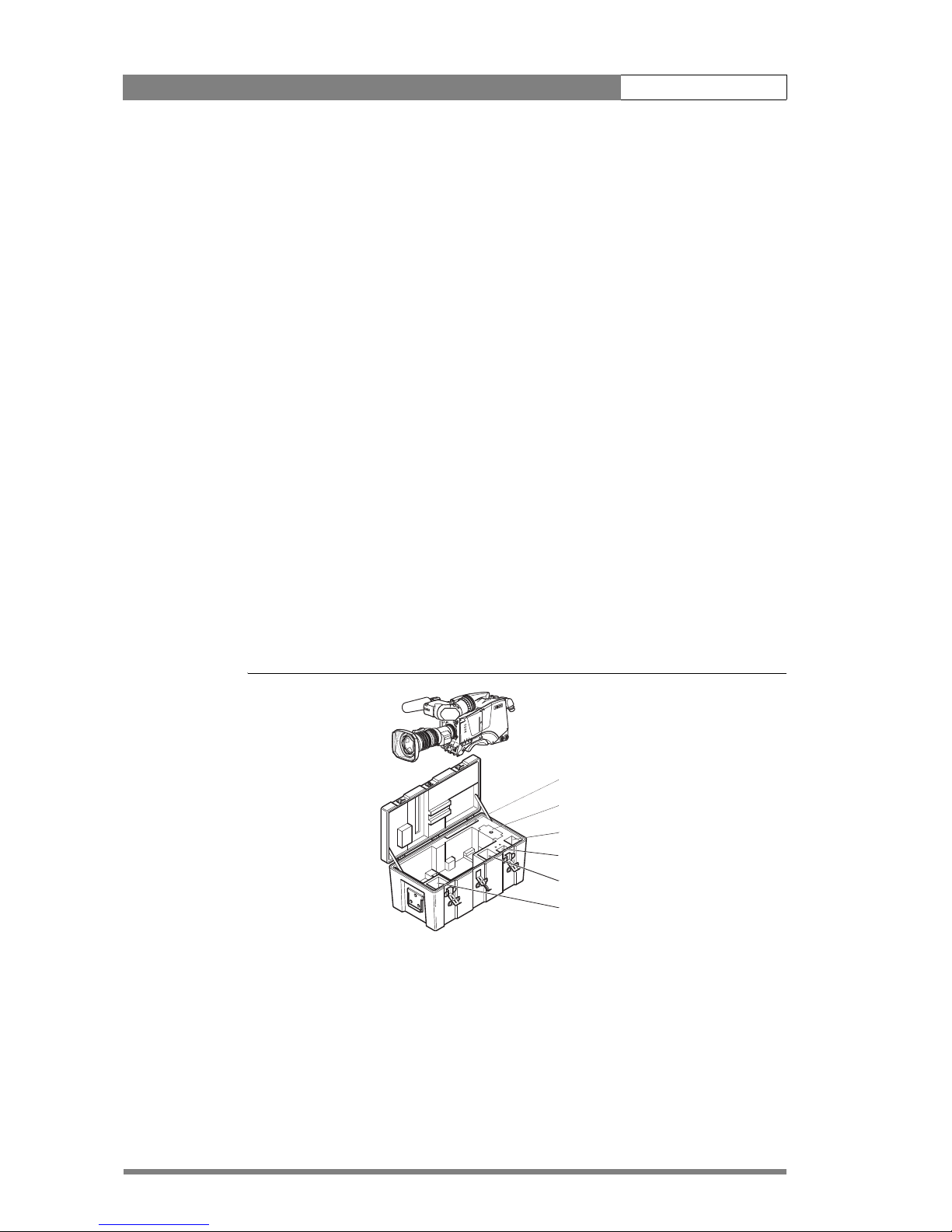
2.2 Transport case
It is important to protect your camera against damage when transporting it. To do this,
a transport case (LDK 5020/00) is optionally available for the camera, lens, viewfinder
and some accessories.
Figure 2-1. Transport case
C
l
e
a
r
C
le
a
r
A
1
S
t
a
r
4
P
N
D
1
/4
B
1
S
t
a
r
6
P
N
D
1
/
1
6
C
1
S
o
f
t
f
o
c
u
s
N
D
1
/
6
4
D
1
Documentation
Packing inserts
Top light
Tripod plate
Battery
Additional supplies
The camera is packed in the transport case as shown in the figure above. This ensures
that the camera is not damaged during transport. Turn the 1.5-inch viewfinder
downwards so that it does not protrude above the top of the camera. Several foam
packing inserts are provided to enable different configurations of the camera to be
packed securely. These inserts are used to support the rear of the camera. Make sure
you use the correct foam insert for your particular configuration.
Installation | Mounting a lens 2-3
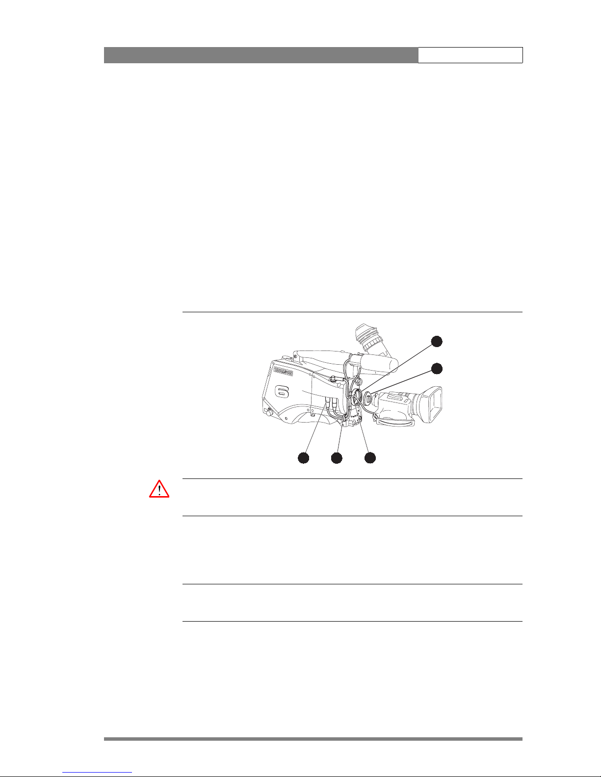
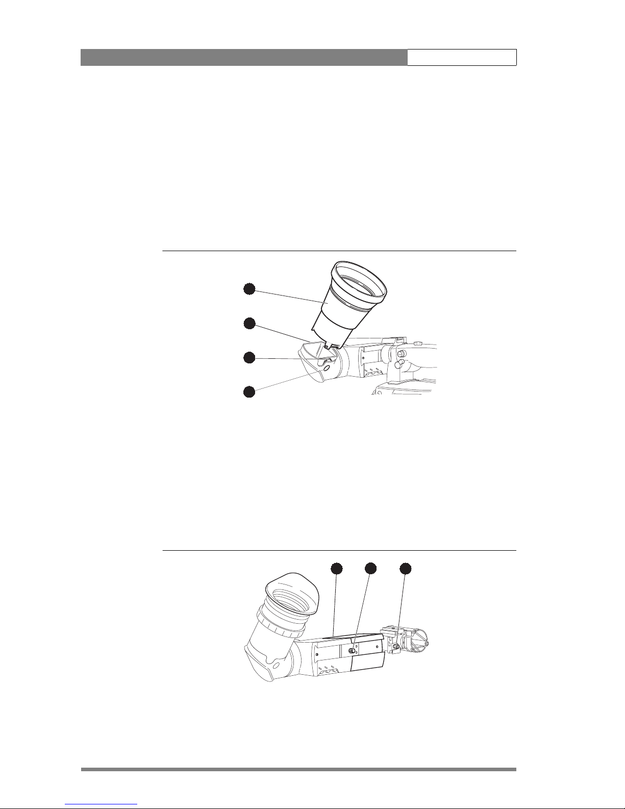
2.3 Mounting a lens
To attach a lens to the camera head proceed as follows:
1. Ensure that the lens locking ring (1) is in the unlocked position - turned
counterclockwise.
2. Remove the dust protection cap (2).
3. Slot the lens into the lens mount (3).
4. Turn the lens locking ring (1) clockwise to lock the lens in place.
5. Connect the lens cable to the lens connector (4) at the right side of the
camera.
6. Place the lens cable into the bottom clip at the front of the camera and clip (5)
located at the side. (Pull and twist clip to open it.)
Figure 2-2. Lens mounting
bts1009
4
5
3
2
1
Caution
Do not attach a lens weighing more than 5 kg to the camera without a support.
When a new lens is fitted to the camera it may be necessary to carry out some
adjustments to optimize its use, for example, back focus or shading. For more
information about these adjustments refer to the lens manufacturer’s documentation
☞
Note
Always mount the dust protection cap when the lens is not connected to the camera.
Installation | 1.5-inch Viewfinder 2-4
2.4 1.5-inch Viewfinder
2.4.1 Mounting viewfinder and microphone holder
To mount the 1.5-inch viewfinder proceed as follows:
1. Loosen locking ring (1) of viewfinder support bracket (2) at the front of the
camera handle. (As seen from the rear of the camera, turning the locking ring
counterclockwise moves it towards the handle.)
2. Slide the viewfinder onto the viewfinder support bracket.
3. Tighten the locking ring (1) by turning it clockwise (as seen from rear) so that
the viewfinder is mounted securely to the support.
4. Connect the viewfinder cable to the viewfinder connector socket (6) at the top
right of the camera.
5. Slide the microphone holder (4) onto the viewfinder and secure with the
knurled screw (5).
Caution
Always fit the microphone holder as it functions as a safety stop for the viewfinder.
6. To improve the comfort of the skin contact when using the viewfinder, fit the
eye piece cover (3) to the rubber eyepiece. Spare eye piece covers
(3922
405 00461) are available at your Thomson Broadcast and Media
Solutions representative.
Figure 2-3. Viewfinder mounting
5
6
4
3
2
1
Installation | 1.5-inch Viewfinder Accessories 2-5
2.4.2 Positioning the viewfinder
The horizontal position of the viewfinder can be adjusted as follows to suit your
requirements:
1. Loosen the locking ring (1). (As seen from the rear of the camera, turning the
locking ring counterclockwise moves it towards the handle.)
2. Slide the viewfinder horizontally along the rail to the desired position.
3. Tighten the locking ring (1) by turning clockwise.
The dioptre hood and eyepiece of the viewfinder can be rotated vertically.
The viewfinder can be positioned backwards and forwards along the camera axis.
Loosen the support bracket round bar retaining lever (2) and slide the round bar (3)
forwards or backwards. When the desired position is reached tighten the support
bracket round bar retaining lever (2) again.
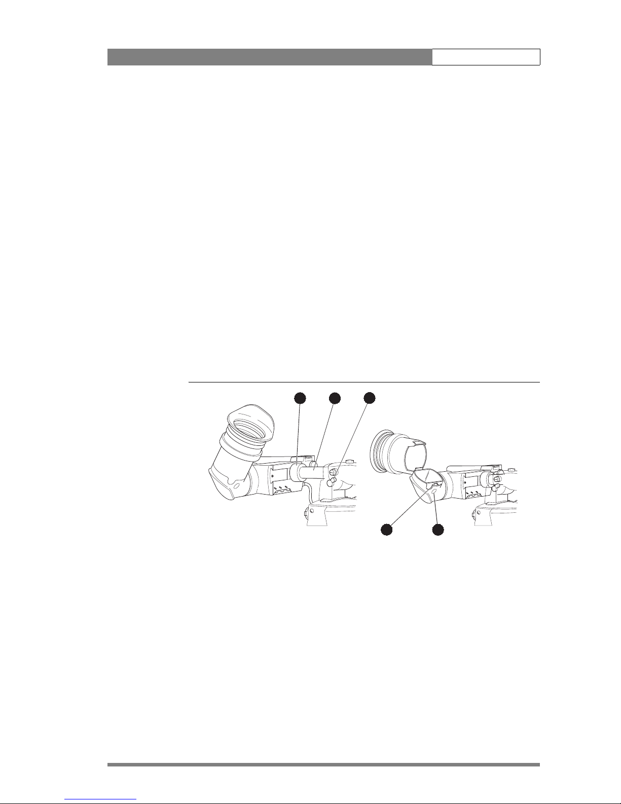
To use the viewfinder at a distance press the button (4) below or above the eyepiece
tube and swing it free of the associated clip (5). The display can now be seen from
further away.
Figure 2-4. Viewfinder positioning
5
4
2
1
3
2.5 1.5-inch Viewfinder Accessories
2.5.1 Wide angle eyepiece
If you regularly use the viewfinder at a distance, for example, when you use the camera
in the hand-held position, it is recommended that you fit the optionally available wide
angle eyepiece (LDK 5390/00).
Installation | 1.5-inch Viewfinder Accessories 2-6
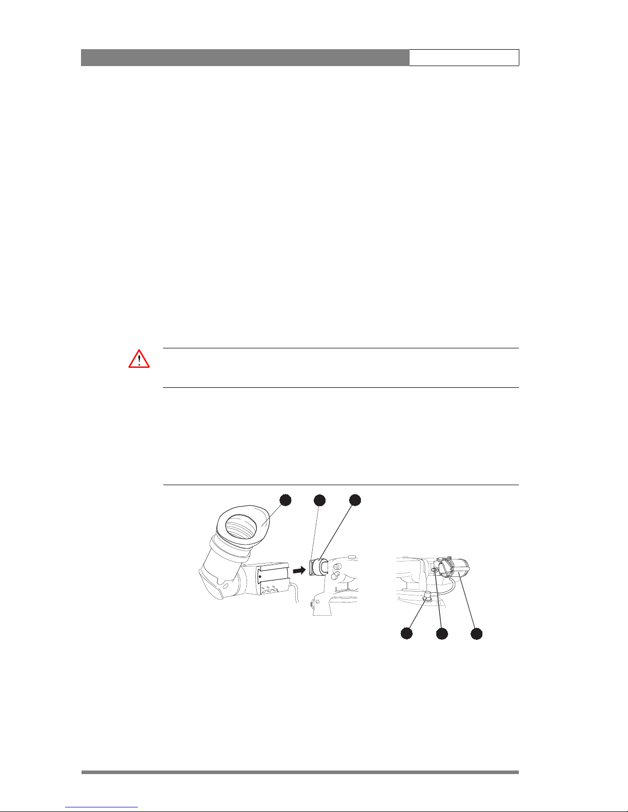
To fit the wide angle eyepiece proceed as follows:
1. Hold the eyepiece (1) securely.
2. Press the button (2) below the eyepiece tube and swing it free of the button
clip (3).
3. Press the button (4) above the eyepiece tube and remove the eyepiece.
4. Fit the wide angle eyepiece (1) to the two clips (3) ensuring that they both click
into place.
Figure 2-5. Viewfinder wide angle eyepiece
4
2
1
3
2.5.2 Left eye adapter
A left eye adapter is optionally available (LDK 5390/10) to allow the viewfinder to be
used with the left eye.
Before mounting the viewfinder onto the camera, attach the left eye adapter (1) to the
viewfinder and secure it using the screw (2). Do not forget to mount the microphone
support bracket (3) at the end of the left eye adapter.
Figure 2-6. Viewfinder left eye adapter
2
1
3
Installation | Mounting a microphone 2-7
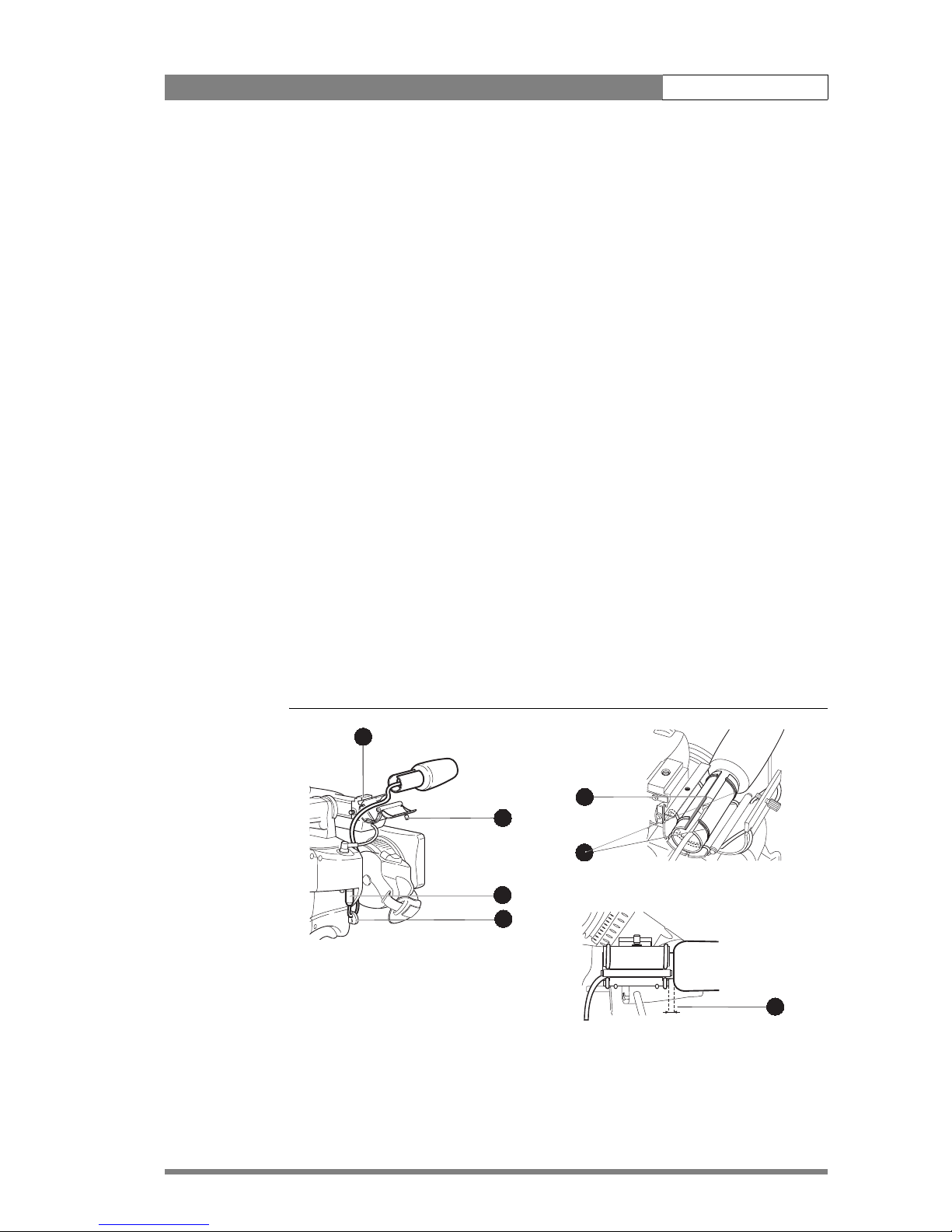
2.6 Mounting a microphone
To attach the optional microphone (AJ MC700) to the camera proceed as follows:
1. Open the microphone holder by unscrewing the knurled screw (2) of the
microphone support bracket (1) on the viewfinder and open.
2. Slide the microphone into the split tube until the microphone shoulder reaches
the mark (5) in the tube.
3. Place the tube with the microphone into the holder with the split facing
upwards. Mount the microphone as straight as possible.
4. Ensure that the rubber supports at the back and front of the holder fit into the
rims (6) around the tube.
5. Close the holder and tighten the knurled screw at the top. Don’t allow the
wind hood to touch the holder (7) as this reduces the damping effect.
6. Connect the microphone cable to the MIC audio connector (3) on the right
side of the camera. To avoid mechanical pick-up, do not let the microphone
cable touch the holder.
7. Place the microphone cable into the top clip at the front of the camera and
into clip (4) at the side of the camera. (Pull and twist clip to open it.)
Other microphones with a diameter of 21mm can also be used, however, ensure that
the phantom power and the sensitivity of the input that match that type of
microphone are correctly selected in the camera systems menu. When a longer
microphone is used, it is not necessary to place it in the split tube.
Figure 2-7. Microphone mounting
2
4
1
3
5
6
7
 Loading...