

GV Keyboard Instruction Manual
2005/03
Instruction Manual
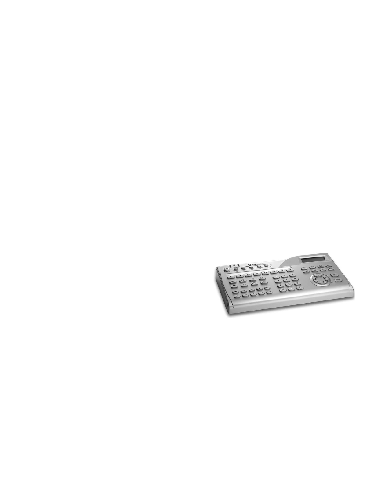
GV-Keyboard
Before attempting to connect or operate this product,
please read these instructions carefully and save this manual for future use.
1
GV-KeyboardGV-Keyboard
Introduction
Packing List
System Requirements
System Connections
Installation
ID & Password Settings in DVRs
Keyboard Overview
Programming and Operation
On-Screen Display Menu
Shortcut key Conflict Test
Troubleshooting
Specifications
1
1
1
2
2
3
4
5
5
7
8
9
10
11
14
15
16
17
18
19
20
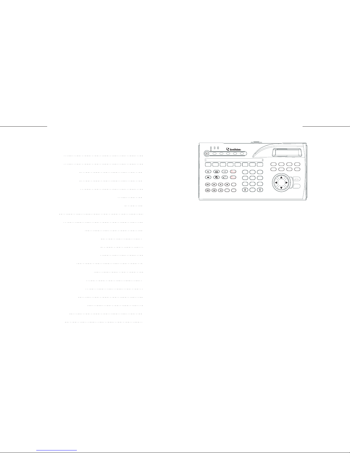
Table of Contents
The GV-Keyboard is used to program and operate GV-Systems. Through
RS-485 configuration, it can control up to 16 additional GV-Systems.
Introduction
Windows 2000 or XP
GV-System V7.0 or above
System Requirements
GV-Keyboard x 1
USB Cable (300 cm) x 1
RS-232 Cable (300 cm) x1
RJ-11 (RS-485) Cable (100 cm) x 1
AC Adapter (Input 100-240 V) x 1
Wall Terminal Block x 1
Packing List
Rear Panel Overview
Connecting GV-Keyboard to One GV-System
Connecting GV-Keyboard to Multiple GV-Systems
USB Driver
GV-Keyboard Application
The OSD in Main System
The OSD in ViewLog
Defining Eight Function Keys
Printing Function Key Labels
1
ALL
123
456
7809
AB
-
REC
REC STOP
SCH
SCH STOP
F1 F2
F3
F4 F5 F6 F7 F8
Zoom
In
Zoom
Out
Focus
In
Focus
Out
Auto
Focus
Auto Preset
Home
OK
Cancel
Menu
Speed
+
Speed
-
RX TX
P1 P2 P3 P4 P5
3
2
GV-KeyboardGV-Keyboard
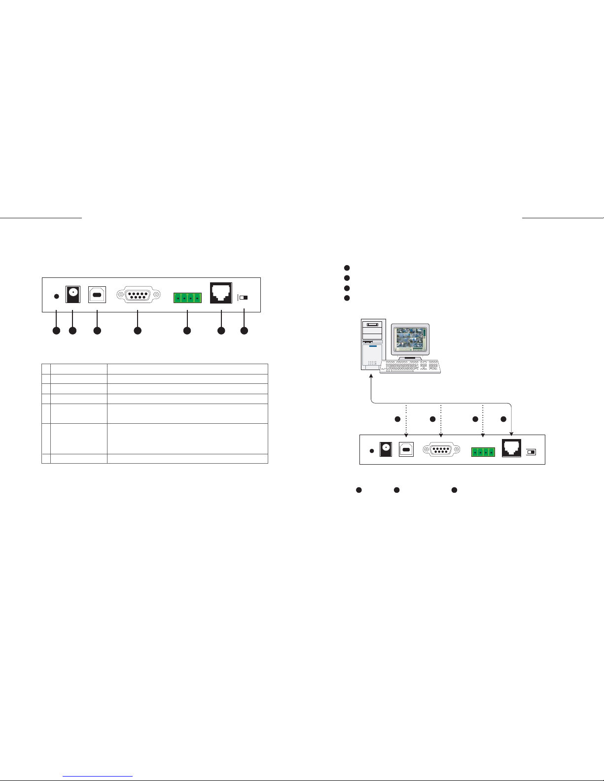
There are four ways to connect the keyboard and one GV-System, using:
USB Port,
RS-232 Port (DC power required),
Terminal Block (DC power required), or
RJ-11 Port (DC power required)
USB cable, RS-232 cable, and RJ-11(RS-485) cable are supplied with
the GV-Keyboard.
Connecting GV-Keyboard to One GV-System
Reset
DC IN 12V Power
USB Port
RS-232 Port
Terminal Block
RJ-11 Port
Terminal Resistance
Resets the keyboard when it does not respond to commands.
Connects to the AC adaptor's DC output plug.
Connects to GV-System.
Connects to GV-System.
The terminal block carries RS-485 signals.
It can connect up to 16 additional GV-Systems.
The RJ-11 port carries RS-485 signals.
Through the wall terminal block, it can connect up to
16 additional GV-Systems.
Used in the last daisy-chained GV-System.
1
2
3
4
5
6
7
RESET
DC 12V USB
RS232 RS485
12V
+
-
G
RS485
OFF NO
TERM
GV-System
GV-Keyboard
21 4
1 2 3 4
1
2
3
4
RESET
DC 12V USB
RS232 RS485
12V
+
-
G
RS485
OFF NO
TERM
*
System Connections
Rear Panel Overview
7654321
5
4
GV-KeyboardGV-Keyboard
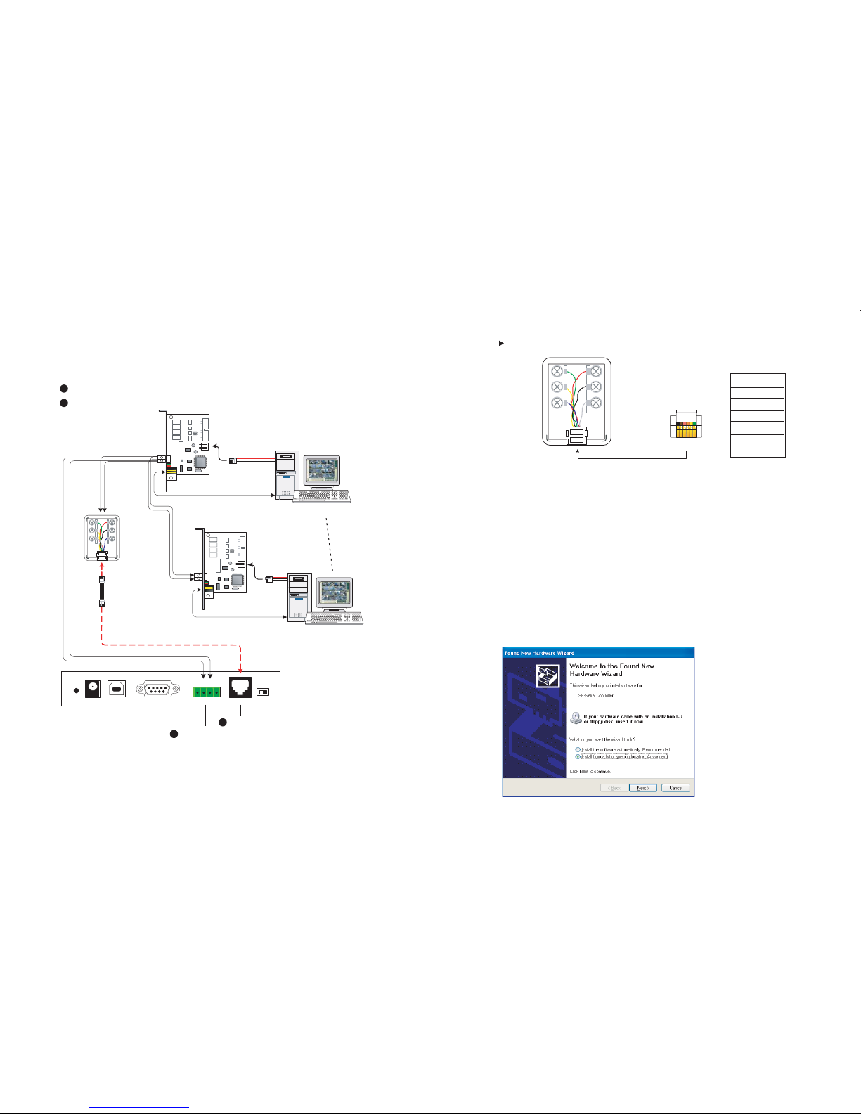
Wall Terminal Block
There are two ways to connect the keyboard and up to 16 additional
GV-Systems within 600 meters, using:
Terminal Block, or
RJ-11 Port
The RJ-11(RS-485) cable and Wall Terminal Block are supplied with the GV-Keyboard.
The GV-Net card can be replaced with other GV products, such as GV-Net,
GV-Net I/O card, and GV-Hub.
When you are using the wall terminal block for connection, the RS-485 + and RS485 - cables should be attached to the appropriate terminal screws.
It's not necessary to use extra power for RS-485 connection if the keyboard
adaptor is connected.
Note:
1.
2.
Use the USB cable to attach the keyboard to GV-System.
The Found New Hardware Wizard detects the keyboard and pops up.
1.
2.
*
**
Connecting GV-Keyboard to Multiple GV-Systems
1
2
1
2
Terminal Block
RJ-11
RESET
DC 12V USB
RS232 RS485
12V+-G
RS485
OFF N O
TERM
RS-485+
RS-485-
Connect s t o PC's
Power Supply
GV-Sys tem 1
Red
Black
White
Pin
1
2
3
4
5
6
Function
GND
12V
DATA-
DATA+
12V
GND
Green
Yellow
Blue
RS-232 (COM port)
Wall Terminal
Block *
RS-485 Cable
to RJ-11 Port *
or
GV-NET C ard **
RS-485+
RS-485-
Connect s to P C's
Power Suppl y
GV-Sys tem 16
RS-232 (COM port)
GV-NET C ard **
1 6
RJ-11 Cable
* RJ-11 Cable
Installation
USB Driver
If you are using the USB port to connect the keyboard and GV-System, it's
necessary to install the USB driver. These instructions are for Windows XP.
Installation under Windows 2000 is similar, but not necessarily identical.
 Loading...