

GV D1010S-046, D1010D-046 Instruction Manual
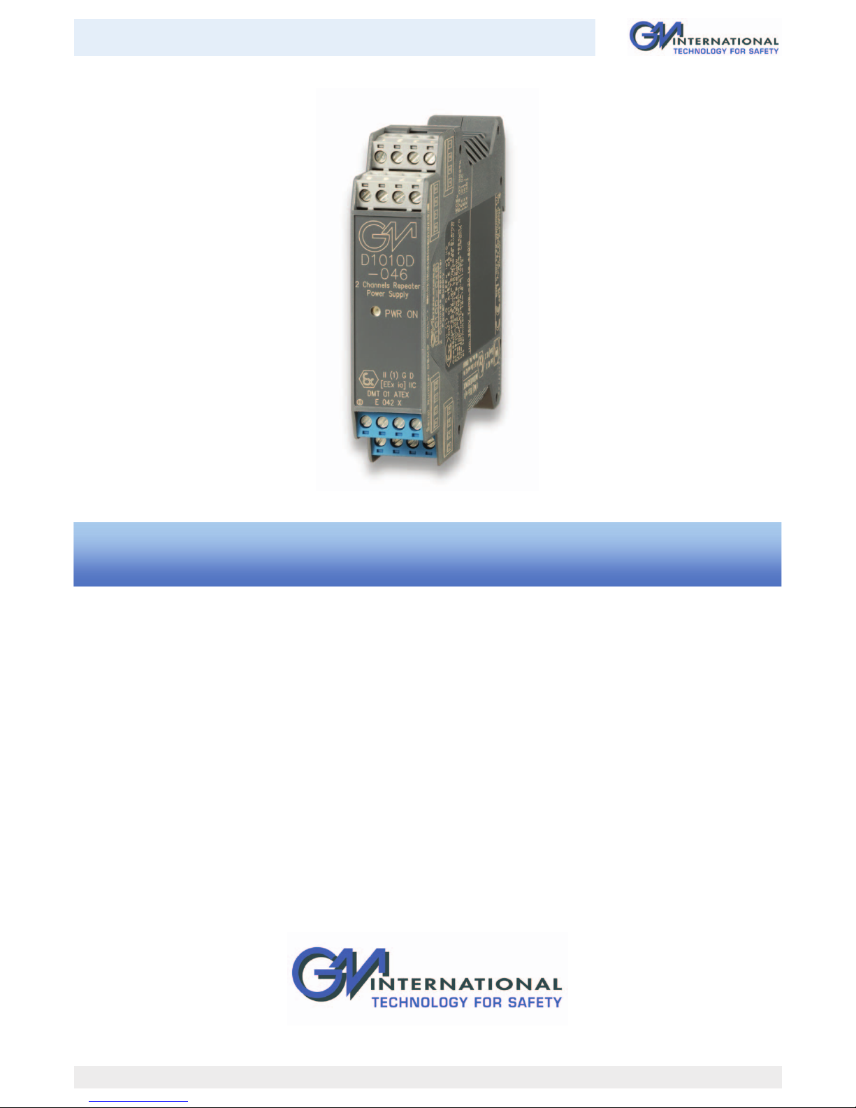
D1010-046 - Repeater Power Supply Smart-Hart compatible ISM0066-8
D1010S-046 - D1010D-046
INSTRUCTION MANUAL
INSTRUCTION MANUAL
Repeater Power Supply
Smart-Hart compatible
DIN-Rail Models D1010S-046, D1010D-046
2
D1010-046 - Repeater Power Supply Smart-Hart compatible G.M. International ISM0066-8
General Description: The single and dual channel DIN Rail Repeater Power Supply, D1010S-046 and D1010D-046, provides a fully floating dc supply for energizing conventional
2 wires 4-20 mA transmitters, or separately powered 3, 4 wires 4-20, 0-20 mA transmitters located in Hazardous Area, and repeats the current in floating circuit to drive a Safe Area load.
The circuit allows bi-directional communication signals, for Hart-Smart transmitters.
Function: 1 or 2 channels I.S. analog input for 2 wires loop powered or separately powered Smart transmitters,
provides 3 port isolation (input/output/supply) and current (source or sink) or voltage output signal.
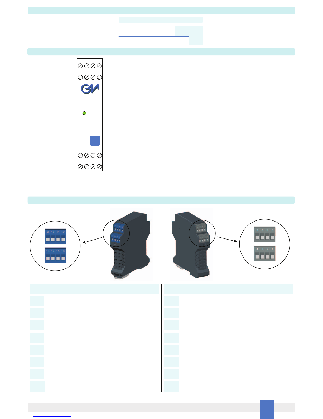
Signalling LED: Power supply indication (green).
Field Configurability: mA (source or sink) or V output signal.
Smart Communication Frequency Band: 0.5 to 40 KHz within 3 dB (Hart and higher frequency protocols).
EMC: Fully compliant with CE marking applicable requirements.
Supply: 24 Vdc nom (20 to 30 Vdc) reverse polarity protected, ripple within voltage limits 5 Vpp.
Current consumption @ 24 V: 115 mA for 2 channels D1010D-046, 60 mA for 1 channel D1010S-046 with 20 mA output typical.
Power dissipation: 1.9 W for 2 channels D1010D-046, 1.0 W for 1 channel D1010S-046 with 24 V supply voltage and 20 mA output typical.
Max. power consumption:
at 30 V supply voltage and short circuit condition, 3.7 W for 2 channels D1010D-046, 2.0 W for 1 channel D1010S-046.
Isolation (Test Voltage): I.S. In/Out 1.5 KV; I.S. In/Supply 1.5 KV; I.S. In/I.S. In 500 V; Out/Supply 500 V; Out/Out 500 V.
Input: 0/4 to 20 mA (separately powered input, voltage drop 1.1 V) or 4 to 20 mA (2 wire Tx current limited at 25 mA).
Transmitter line voltage: 14.0 V at 20 mA with max. 20 mVrms ripple on 0.5 to 40 KHz frequency band.
Output: 0/4 to 20 mA, on max. 600 load in source mode; V min. 5 V at 0 load V max. 30 V in sink mode, current limited at 23 mA or 0/1 to 5 V on internal 250 shunt
(or 0/2 to 10 V on internal 500 shunt on request).
Response time: 50 ms (10 to 90 % step change).
Output ripple: 20 mVrms on 250 communication load on 0.5 to 40 KHz band.
Frequency response: 0.5 to 40 KHz bidirectional within 3 dB (Hart and higher frequency protocols).
Performance: Ref. Conditions 24 V supply, 250 load, 23 ± 1 °C ambient temperature.
Calibration accuracy: ± 0.1 % of full scale.
Linearity error: ± 0.05 % of full scale.
Supply voltage influence: ± 0.05 % of full scale for a min to max supply change.
Load influence: ± 0.05 % of full scale for a 0 to 100 % load resistance change.
Temperature influence: ± 0.01 % on zero and span for a 1 °C change.
Compatibility:
CE mark compliant, conforms to 94/9/EC Atex Directive and to 2004/108/CE EMC Directive.
Environmental conditions: Operating: temperature limits -20 to + 60 °C, relative humidity max 90 % non condensing, up to 35 °C.
Storage: temperature limits – 45 to + 80 °C.
Safety Description:
II (1) G [Ex ia Ga] IIC, II (1) D [Ex ia Da] IIIC, I (M1) [Ex ia Ma] I, II 3G Ex nA II T4, [Ex ia Ga] IIC, [Ex ia Da] IIIC, [Ex ia Ma] I associated electrical apparatus.
Uo/Voc = 26.3 V, Io/Isc = 79 mA, Po/Po = 514 mW at terminals 14-15, 10-11.
Uo/Voc = 1.1 V, Io/Isc = 28 mA, Po/Po = 8 mW at terminals 15-16, 11-12. Ui/Vmax = 30 V, Ii/Imax = 104 mA, Ci = 1.05 nF, Li = 0 nH at terminals 15-16, 11-12.
Um = 250 Vrms, -20 °C Ta 60 °C.
Approvals:
DMT 01 ATEX E 042 X conforms to EN60079-0, EN60079-11, EN60079-26, EN61241-0, EN61241-11,
IECEx BVS 07.0027X conforms to IEC60079-0, IEC60079-11, IEC60079-26, IEC61241-0, IEC61241-11, IMQ 09 ATEX 013 X conforms to EN60079-0, EN60079-15,
Russia according to GOST 12.2.007.0-75, R 51330.0-99, R 51330.10-99 [Exia] IIC X.
Mounting:
T35 DIN Rail according to EN50022.
Weight: about 175 g D1010D-046, 125 g D1010S-046.
Connection: by polarized plug-in disconnect screw terminal blocks to accomodate terminations up to 2.5 mm
2
.
Location: Safe Area or Zone 2, Group IIC T4 installation.
Protection class: IP 20.
Dimensions: Width 22.5 mm, Depth 99 mm, Height 114.5 mm.
Technical Data
Characteristics
3
D1010-046 - Repeater Power Supply Smart-Hart compatible G.M. International ISM0066-8
Ordering information
Model: D1010
1 channel S-046
Power Bus enclosure
2 channels
D-046
/B
Front Panel and Features
1 2 3 4
9 10 11 12
16 15 14 13
5 6 7 8
PWR ON
D1010
-046
• Input from Zone 0 (Zone 20), installation in Zone 2.
• 4-20 or 0-20 mA Input, Output Signal.
• Wide Band Smart Communication, Hart compatible.
• Input and Output short circuit proof.
• High Accuracy.
• Three port isolation, Input/Output/Supply.
• EMC Compatibility to EN61000-6-2, EN61000-6-4.
• In-field programmability by DIP Switch.
• ATEX, IECEx, Russian Certifications.
• High Reliability, SMD components.
• High Density, two channels per unit.
• Simplified installation using standard DIN Rail and plug-in terminal blocks.
• 250 Vrms (Um) max. voltage allowed to the instruments associated with the barrier.
Not used
HAZARDOUS AREA SAFE AREA
+ Input Ch 2 for 2 wire Transmitters
- Input Ch 2 for 2 wire Transmitters or
+ Input Ch 2 for External Powered Transmitters
- Input Ch 2 for External Powered Transmitters
Not used
+ Input Ch 1 for 2 wire Transmitters
- Input Ch 1 for 2 wire Transmitters or
+ Input Ch 1 for External Powered Transmitters
- Input Ch 1 for External Powered Transmitters
9
10
11
12
13
14
15
16
+ Output Ch 1 for Current Source mode or
+ Output Ch 1 for Voltage Source mode
1
- Output Ch 1 for Current Source mode or - Output Ch 1 for
Voltage Source mode or + Output Ch 1 for Current Sink mode
2
+ Power Supply 24 Vdc
3
- Power Supply 24 Vdc
4
+ Output Ch 2 for Current Source mode or
+ Output Ch 2 for Voltage Source mode
5
- Output Ch 2 for Current Source mode or - Output Ch 2 for
Voltage Source mode or + Output Ch 2 for Current Sink mode
6
- Output Ch 2 for Current Sink mode
7
- Output Ch 1 for Current Sink mode
8
Terminal block connections
4
D1010-046 - Repeater Power Supply Smart-Hart compatible G.M. International ISM0066-8
Parameters Table
Must
be
Hazardous Area
Device Parameters
D1010-046 Associated
Apparatus Parameters
Must
be
Hazardous Area
Device + Cable Parameters
Uo / Voc = 26.3 V
Ui / Vmax
In the system safety analysis, always check the Hazardous Area devices to conform with the related system documentation, if the device is Intrinsically Safe check its suitability for the
Hazardous Area and gas group encountered and that its maximum allowable voltage, current, power (Ui/Vmax, Ii/Imax, Pi/Pi) are not exceeded by the safety parameters
(Uo/Voc, Io/Isc, Po/Po) of the D1010-046 series Associated Apparatus connected to it. Also consider the maximum operating temperature of the field device, check that added
connecting cable and field device capacitance and inductance do not exceed the limits (Co/Ca, Lo/La, Lo/Ro) given in the Associated Apparatus parameters for the effective gas group.
See parameters on enclosure side and the ones indicated in the table below:
D1010-046
Terminals
Ch1
Ch2
14 - 15
10 - 11
Uo / Voc = 1.1 V
Ch1
Ch2
15 - 16
11 - 12
Io / Isc = 79 mA
Ch1
Ch2
14 - 15
10 - 11
Io / Isc = 28 mA
Ch1
Ch2
15 - 16
11 - 12
Po / Po = 514 mW
Ch1
Ch2
14 - 15
10 - 11
Po / Po = 8 mW
Ch1
Ch2
15 - 16
11 - 12
Ii/ Imax
Pi / Pi
D1010-046
Terminals
Ch1
Ch2
14 - 15
10 - 11
Ch1
Ch2
15 - 16
11 - 12
Ch1
Ch2
14 - 15
10 - 11
Ch1
Ch2
15 - 16
11 - 12
Ch1
Ch2
14 - 15
10 - 11
Ch1
Ch2
15 - 16
11 - 12
D1010-046 Associated
Apparatus Parameters
Ci / Ci device + C cable
Li / Li device + L cable
Li / Ri device and
L cable / R cable
(IIC-A, B)
Co / Ca = 95 nF
Co / Ca = 738 nF
Co / Ca = 2.508 µF
(IIB-C)
(IIA-D)
(IIC-A, B)
Co / Ca = 100 µF
Co / Ca = 1000 µF
Co / Ca = 1000 µF
(IIB-C)
(IIA-D)
(IIC-A, B)
Lo / La = 5.8 mH
Lo / La = 23.2 mH
Lo / La = 46.5 mH
(IIB-C)
(IIA-D)
(IIC-A, B)
Lo / La = 45.3 mH
Lo / La = 181.4 mH
Lo / La = 362.8 mH
(IIB-C)
(IIA-D)
(IIC-A, B)
Lo / Ro = 69.2 µH/
Lo / Ro = 276.8 µH/
Lo / Ro = 553.6 µH/
(IIB-C)
(IIA-D)
(IIC-A, B)
Lo / Ro = 4654 µH/
Lo / Ro = 18618 µH/
Lo / Ro = 37236 µH/
(IIB-C)
(IIA-D)
 Loading...