

GUV Control System Cooper Lighting Solutions Installation Manual
Installation Instructions
GUV Control System
Cooper Lighting Solutions
GUV Control System
READ AND FOLLOW ALL SAFETY INSTRUCTIONS.
SAVE AND KEEP THESE INSTRUCTIONS WITH THE CONTROL PANEL.
Failure to comply with these instructions may result in death, serious bodily injury and property damage.
GUV Control System should only be operated by authorized personnel. Before operation, the installer must
complete and submit a checklist to Cooper Lighting Solutions to ensure the control system is installed correctly.
GUV Important Safeguards
a. READ AND FOLLOW ALL SAFETY INSTRUCTIONS
b. Safe use of this UV equipment relies primarily on equipment and site safeguards. It is the installer’s
responsibility to ensure that equipment is installed in accordance to the manufacturer’s instructions.
c. It is the operator’s responsibility to ensure the equipment is used in accordance with the manufacturer’s user guide.
(i.e. The device is operated when the room is unoccupied.)
d. This equipment is designed for use with germicidal xtures and must be installed in compliance with competent technical
directions to prevent the user’s eyes and bare skin from exposure to harmful UVC radiation.
e. UV radiation can reect off surrounding surfaces and may pass through certain clear or translucent materials. Follow the
manufacturer’s recommended practice for spacing this equipment from nearby objects and surfaces. Contact the manufacturer
for further guidance.
f. Equipment should be mounted in locations and at heights where it will not readily be subjected to tampering by unauthorized
personnel.
g. This equipment uses user-replaceable lamps, replace them only with the lamps for which the equipment is marked and intended.
h. The use of accessory equipment not recommended by the manufacturer may cause an unsafe condition.
i. Do not use this equipment for other than its intended use.
WARNING
Risk of Fire, Electrical Shock, Cuts or other Casualty Hazards- Installation and maintenance of this product must be
performed by a qualied electrician. This product must be installed in accordance with the applicable installation code
by a person familiar with the construction and operation of the product and hazards involved.
Risk of Fire and Electric Shock- Make certain power is OFF before starting installation or attempting any maintenance.
Disconnect power at fuse or circuit breaker.
Risk of Fire- Minimum 90°C supply conductors.
Risk of Personal Injury- Due to sharp edges, handle with care.
FCC Regulations state that any unauthorized changes or modications to this equipment not expressly approved by the
manufacturer could void the user’s authorization to operate this equipment.
GUV Control System should only be operated by authorized personnel. Before operation, the installer must complete
and submit a checklist to Cooper Lighting Solutions to ensure the control system is installed correctly.
DISCLAIMER OF LIABILITY: Cooper Lighting Solutions assumes no liability for damages or losses of any kind that may arise
from the improper, careless, or negligent installation, handling or use of this product.
IMPORTANT: Read carefully before installing product. Retain for future reference.
NOTICE: Product may become damaged and/or unstable if not installed properly.
Note: Specications and dimensions subject to change without notice.
ATTENTION Receiving Department: Note actual product description of any shortage or noticeable damage on delivery receipt. File claim for common
carrier (LTL) directly with carrier. Claims for concealed damage must be led within 15 days of delivery. All damaged material, complete with original
packing must be retained.
GENERAL: Upon receipt of controller thoroughly inspect for any freight damage, which should be brought to the attention of the delivery carrier.
Compare the catalog description listed on the packing slip with the label on the controller to assure you have received the correct parts.
NOTICE: These instructions do not claim to cover all details or variations in the equipment, procedure, or process described, or to provide directions
for meeting every possible contingency during installation, operation or maintenance. When additional information is desired to satisfy a problem not
covered suciently for user’s purpose, please contact your nearest representative.
NOTICE: Proper grounding is required to insure personal safety. Carefully observe grounding procedure under installation section.
CAUTION: See ratings on controller for appropriate voltage. Any other connection voids the warranty.
GUV Control SystemCooper Lighting Solutions
FCC Statement
This device complies with part 15 of the FCC Rules. Operation is subject to the following two conditions: (1) This device may not
cause harmful interference, and (2) this device must accept any interference received, including interference that may cause undesired
operation.
This equipment has been tested and found to comply with the limits for a Class A digital device, pursuant to part 15 of the FCC
Rules. These limits are designed to provide reasonable protection against harmful interference when the equipment is operated in a
commercial environment. This equipment generates, uses, and can radiate radio frequency energy and, if not installed and used in
accordance with the instruction manual, may cause harmful interference to radio communications. Operation of this equipment in a
residential area is likely to cause harmful interference in which case the user will be required to correct the interference at his own
expense.
FCC Regulations state that any unauthorized changes or modications to this equipment not expressly approved by the manufacturer
could void the user’s authorization to operate this equipment.
General Information
Following the instructions provided in this document is vital to ensure the GUV Control System is wired and installed correctly.
The GUV Control System is specifically designed to for the safe operation of Cooper Lighting Solutions’ GUV fixtures when installed
correctly, the system will:
1. Verify the area to be disinfected has been thoroughly inspected for occupants.
2. Ensure all points of entry including doors, windows and pass-throughs are closed.
3. Shut off fixtures automatically if anyone enters the space during operation.
Items needed for Site Installation and Commissioning
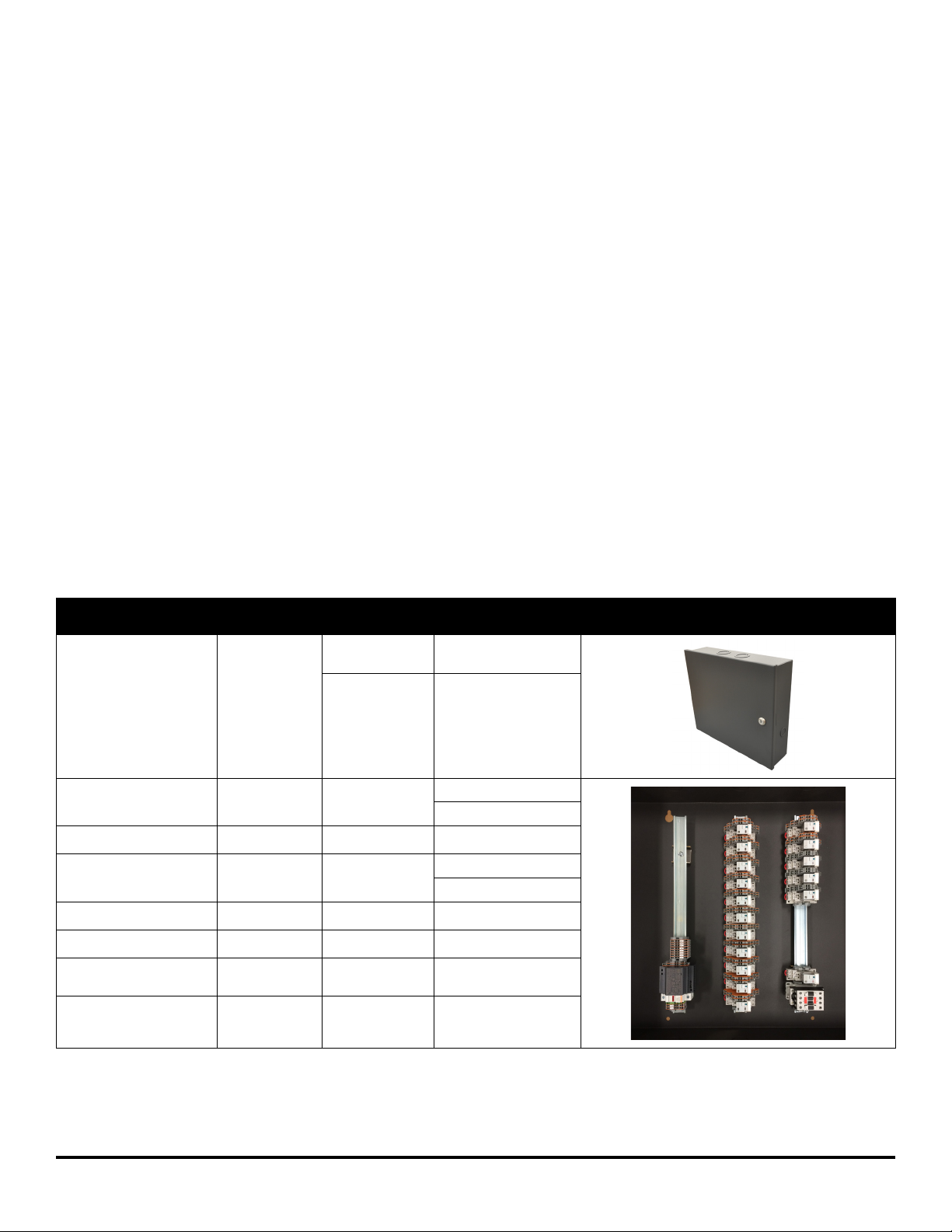
GUV Control Panel
Part Name
GUV Control Panel Onsite
Control Relay
Relay Socket
High Current Relay Factory DPBF09 10 D024
Timer
Timer Socket
Control Power Supply Factory Phoenix Contact 2904945
Circuit Protector Factory F1 CCP2-1-30CC
Terminal blocks Factory
All Class 2 Wiring except
for the branch circuit
power for the box
Factory/Onsite
Installed
Factory
Factory
Onsite For all class 2 wiring
Designator
or MFG
GUV-16-120-277
GUV-24-120-277
Part
Information
Supplied Panel with
16 Inputs
Supplied Panel with
24 Inputs
782-2C-24D
782-2C-SKT
MS4SA-CE-ADC
TP411X
Wago 2002
(all connection points)
IB503096ML page 2
October 2020
www.cooperlighting.com
GUV Control System Cooper Lighting Solutions
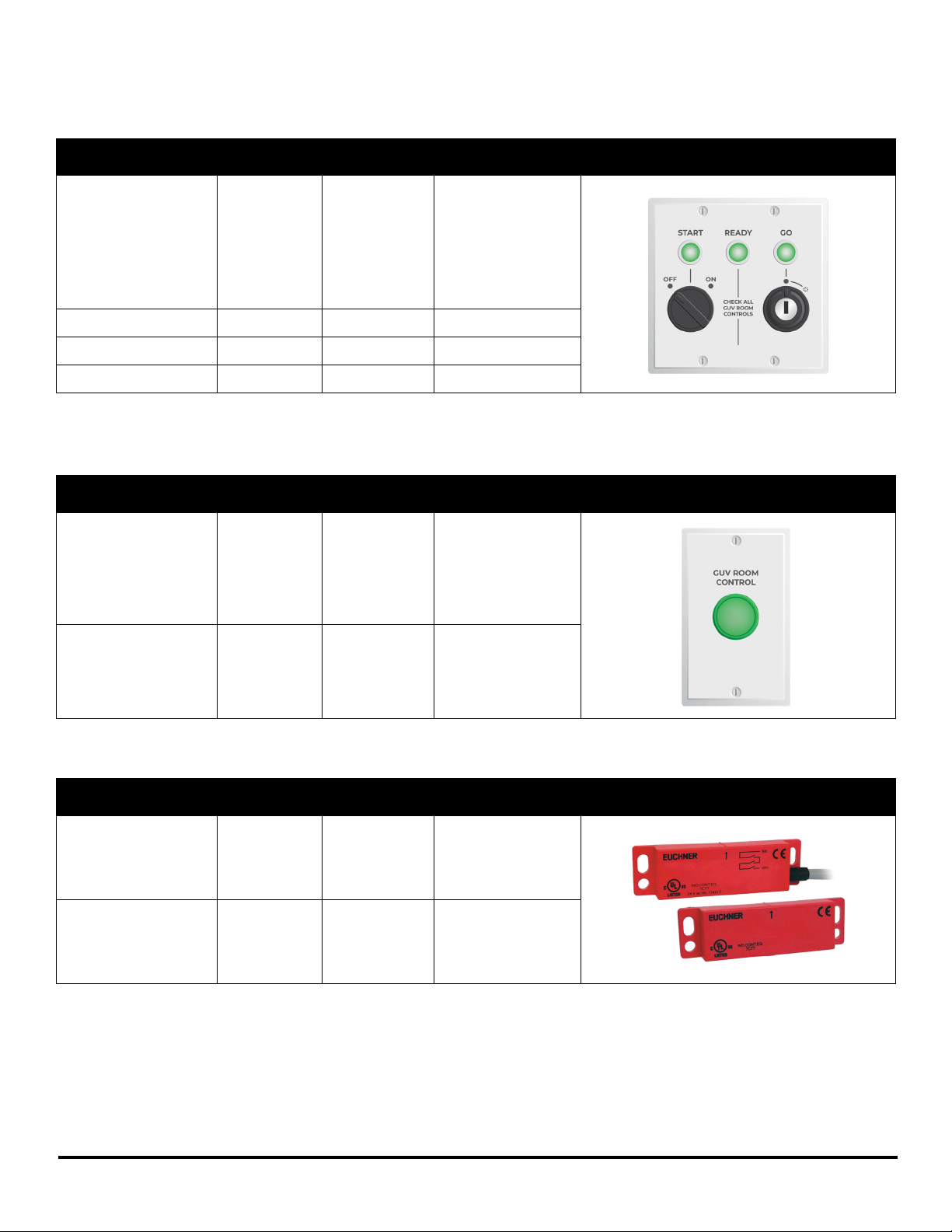
GUV User Station
Part Name
Factory/Onsite
Installed
Designator
or MFG
GUV User Station
Includes: selector
switch, key switch,
GUV User Station
Onsite GUV-USER-1
and panel light with
leads assembly is
prebuilt and only
wiring, and mounting
is required.
Panel Light with Leads Factory 20C843
Selector Switch Factory FUJII GCX3300
Key switch Factory FUJII GCX3430
GUV Clearance Pushbutton
Part Name
Factory/Onsite
Installed
Designator
or MFG
GUV Clearance
Pushbutton
Pushbutton kit
with plate
Onsite GUV-PB-1
Includes: a single
gang mounting plate
for every pushbutton
for ease of installation
Part
Information
Part
Information
All Class 2 Wiring Onsite
600V rated, 90C,
20AWG min
Contact Closures for doors/windows/openings
For all class 2 wiring
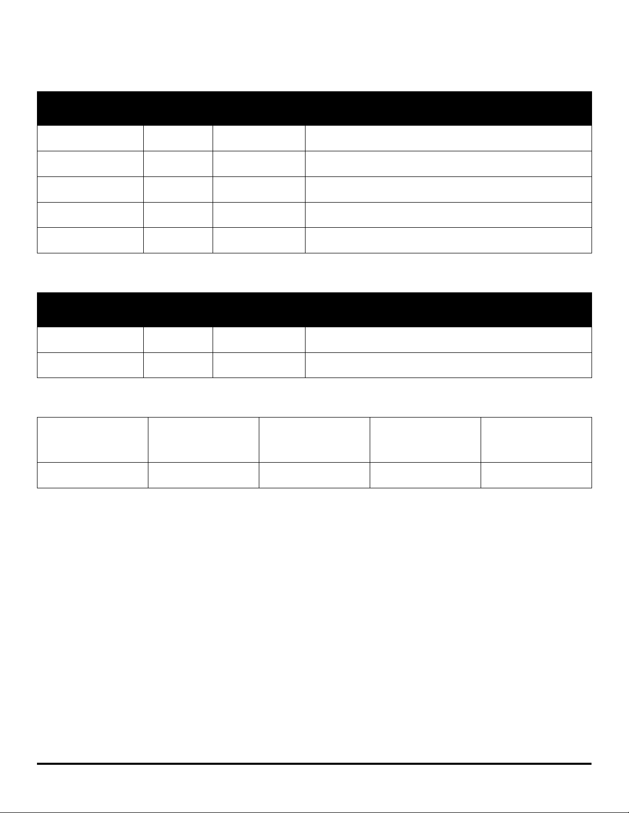
Part Name
Contact Closure /
GUV Magnetic
Access Sensor
Factory/Onsite
Installed
Onsite
Designator
or MFG
GUV-MAGSENSOR-1
Part
Information
CMS-R-AXF-03B
CMS-M-AB
Light Curtain Onsite Contrinex YCA-50S4-3400-G012
www.cooperlighting.com
IB503096ML page 3
October 2020
UV Emitters
GUV Control SystemCooper Lighting Solutions
Part Name
GH Germicidal UV
High Bay
GSL Germicidal UV
Striplight
GTR Germicidal UV
Troffer
GUC Germicidal UV
Undercabinet
GLR Germicidal UV
Louvered Recessed
UV Emitters
Part Name
UHB Germicidal UV
High Bay
UST Germicidal UV
Striplight
Factory/Onsite
Installed
Onsite
Onsite
Onsite
Onsite
Onsite
Factory/Onsite
Installed
Onsite
Onsite
Designator
or MFG
Cooper Lighting
Solutions Fail-Safe
Cooper Lighting
Solutions Fail-Safe
Cooper Lighting
Solutions Fail-Safe
Cooper Lighting
Solutions Fail-Safe
Cooper Lighting
Solutions Fail-Safe
Designator
or MFG
Alkco by Signify
Lighting NA
Alkco by Signify
Lighting NA
Part Information
(*1) = # Lamps (*2) = Lamp Type
(*3) = Distribution (*4) = Ballast Type (*5) = Wire Guard/Louver
GH - (*1) - (*2) - (*3) - (*4)
GSL - (*1) - (*2) - (*3) - (*4)
24GTR - (*5) - (*1) - (*2) - (*4)
GUC - (*1) - (*2) - (*4)
24GLR - (*2) - (*5) - (*4)
Part Information
(*1) = # Lamps (*2) = Lamp Type
(*3) = Ballast Type
UHB - (*1) - (*2) - (*3)
UST - (*1) - (*2) - (*3)
Technical Documentation
UV Layout Factory
GUV System Verification Onsite review
Plan for layout of UV
fixtures and controls
Filled out by installer and
approved by AHJ
Supplied by
Cooper Lighting Solutions
Layout diagram of UV
emitters and Controls
provided by CLS and
approved by Installer
Included in
Installation instructions
IB503096ML page 4
October 2020
www.cooperlighting.com
GUV Control System Cooper Lighting Solutions
Getting Started
1. Do not discard these installation instructions. Please keep for future reference and operation information.
2. Always disconnect all power before wiring or servicing.
3. Use only as intended and at the rated voltage.
4. All installation service must be performed by qualified personnel or service technicians.
5. Install in accordance with National Electrical Code and any other codes that may apply.
6. Multiple sources of high voltage are present inside the controller enclosure. Use extreme caution when performing maintenance
on this equipment.
7. It is recommended that all low voltage wiring be done with power removed to protect components from potential shorts during
the wiring process.
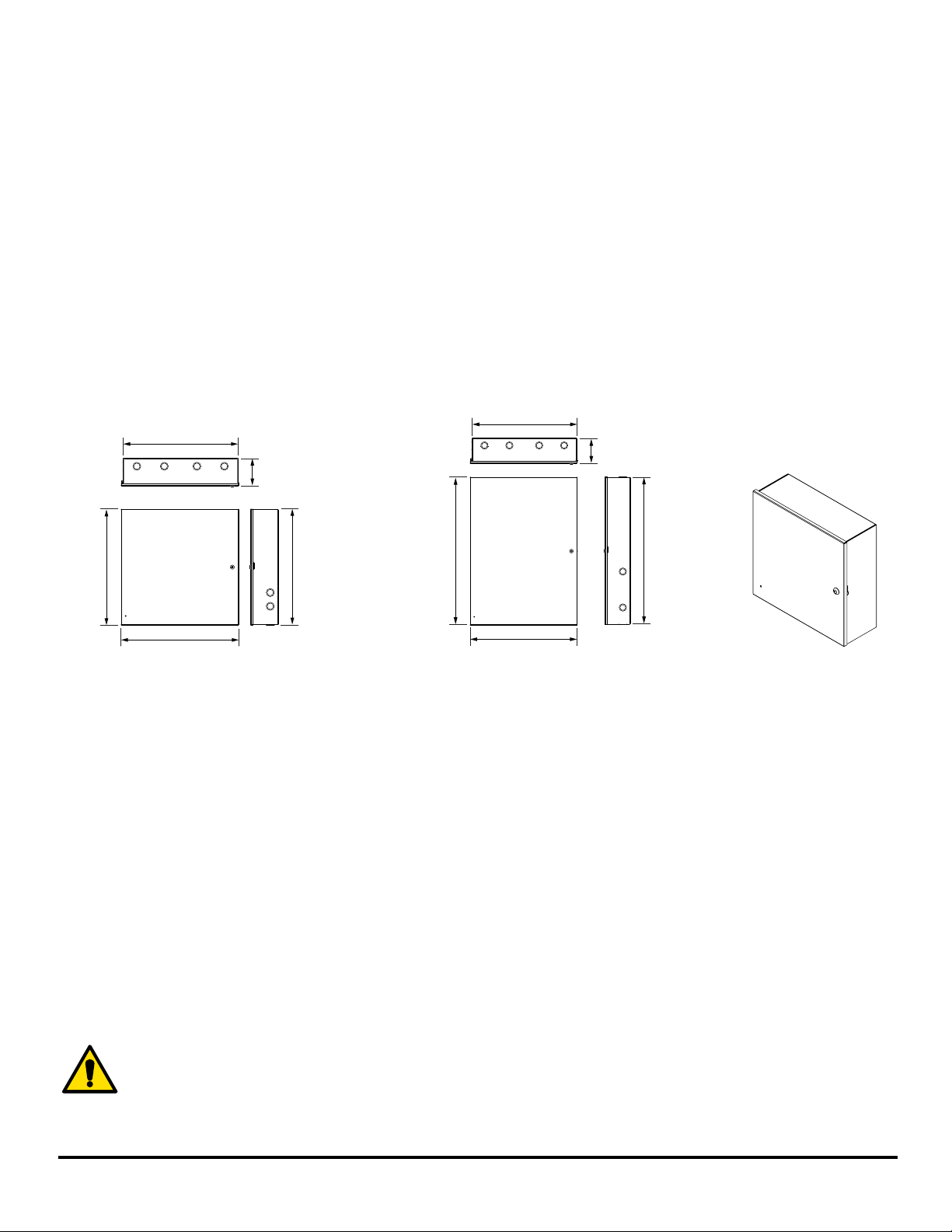
Mounting the GUV Control Panel
25-5/32” [639mm]
25-1/8” [638mm]
6-1/16”
[154mm]
6-1/16”
[154mm]
25-11/32”
[644mm]
25-43/64” [652mm]
Medium panel configuration
25-1/8”
[638mm]
35-35/64”
[903mm]
25-47/64” [654mm]
Large panel configuration
35-19/64”
[896mm]
1. Choose an indoor dry location convenient to the circuit breaker panel. The GUV control panel comes in medium and large sizes.
2. Mount the enclosure on a firm surface using predrilled holes.
3. A minimum of 14 inches (360 mm) must be maintained from the front of the chassis to any other components or walls.
Please make sure to check and follow local code requirements if additional clearance is needed per code in your area.
4. Allow space to open door.
5. Allow adequate space for future maintenance of the unit. Do not install in a location that will later be difficult to access.
6. Enclosure is designed to be mounted vertically.
7. Use suitable conduits and couplers to link the raceways to the enclosure.
8. Remove all cuttings and dirt.
ote: N Make certain that high voltage and low voltage wiring enters the enclosure separately. High voltage wiring should be brought
into the left and right sides of the enclosure. Low voltage wiring should enter from the top of side of the enclosure.
The enclosure is fully convection cooled; therefore, it is important to ensure that each unit is installed in a
ventilated location that permits enough airflow to remove heat and provide correct operating environment. The
cabinets do not contain fans. Allowing airflow around the panel will enhance the reliability and longevity of all
models. Locating panels away from heat generating equipment will also benefit long term reliability. Ensure that
the stated ambient atmosphere requirements are not exceeded.
www.cooperlighting.com
IB503096ML page 5
October 2020
 Loading...