

mega macs PC
.
User Manual
Original User Manual
HBMMPCV5400EN0818S0
460 987-91 / 08.18
en

Table of Contents
mega macs PC
Table of Contents
1 About this Manual ...............................................................................................................................8
1.1 Reading the Manual..............................................................................................................8
1.2 Marking of Text Parts ...........................................................................................................9
2 User Information ............................................................................................................................... 10
2.1 Safety Precautions .............................................................................................................10
2.1.1 General Safety Precautions ...................... ..... ..... ..... ............... ........................ ..... ..... ..... ......... 10
2.1.2 Safety Precautions – Risk of Injury .. ........................ ..... .......... ............... ........................ ..... ..... 10
2.1.3 Safety Precautions for the PC VCI.. ..... ..... ........................ .......... ..... .......... ........................ ..... .. 11
2.1.4 Safety Precautions for High Voltage/Line Voltage..................... ............... ..... ..... ..... .................... 12
2.1.5 Safety Precautions for Hybrid/Electric Vehicles .... ..... ..... ..... .................................. ..... ..... ..... ...... 13
2.2 Non-Liability ..................................................................................................................... 13
2.2.1 Software.... ..... .......... ........................ ..... ..... ..... ..... .................................. ..... ..... ..... ............. 13
2.2.1.1 Safety-Relevant Software Modifications ................... ..... ..... ..... ........................ ............... ..... ..... 13
2.2.1.2 Performing Safety-Relevant Software Modifications . ..... ..... ........................ ............... ..... ..... ..... .. 14
2.2.1.3 Prohibition of Safety-Relevant Software Modifications ..... .......... ............... ........................ ..... ..... 14
2.2.1.4 Waiver of the Use of Safety-Relevant Software Modifications . ..... ....................................... ..... ..... 14
2.2.2 Non-Liability .............. ........................ ..... ..... ..... .................................. ..... ..... ..... ..... ............ 14
2.2.2.1 Data and Information ....................... ..... ..... ..... ....................................... ..... ..... ..... ................ 14
2.2.2.2 Burden of Proof on the User... ............... ............... ........................ ..... ..... ..... ............... ............ 15
2.2.3 Data Protection .................... ............... ............... ........................ ..... ..... ..... ............... ............ 15
2.2.4 Documentation ... ............... ........................ ..... ..... ..... .................................. ..... ..... ..... ..... ..... 15
3 Device Description ............................................................................................................................ 16
3.1 Delivery Contents...............................................................................................................16
3.1.1 Checking Delivery Contents.... ..... ..... ..... ....................................... ..... ..... ..... ........................... 16
3.2 Intended Use...................................................................................................................... 17
3.3 Using the Bluetooth® Function.............................................................................................17
3.4 Range of Functions.............................................................................................................17
3.5 Connectors ........................................................................................................................ 17
3.5.1 Meaning of the Flashing Frequencies ................ ..... .......... ............... ........................ ..... ..... ..... .. 18
4 Installation of the Hella Gutmann Drivers Package............................................................................... 19
4.1 System Requirements of Hella Gutmann Drivers ..................................................................19
4.2 Installation of the Hella Gutmann Drivers Package................................................................19
5 Contents of the mega macs PC Software ............................................................................................. 20
5.1 Diagnostic Functions ..........................................................................................................20
5.2 Additional Functions and Contents (Depending on the License Type) ...................................... 20
6 Installation of the mega macs PC ....................................................................................................... 21
2

mega macs PC
Table of Contents
6.1 Supported Operating Systems for the mega macs PC ............................................................ 21
6.2 System Requirements for the mega macs PC........................................................................ 21
6.3 Installing the mega macs PC Software ................................................................................. 21
7 Putting the mega macs PC into Operation ........................................................................................... 22
7.1 Connection to the PC VCI..................................................................................................... 22
7.2 Executing the mega macs PC Software ................................................................................22
7.3 License Release ................................................................................................................. 23
7.4 Closing the mega macs PC Software .................................................................................... 23
8 Installation of the HGS PassThru Software ..........................................................................................24
8.1 Provision of HGS PassThru.................................................................................................. 24
8.2 Supported Operating Systems for HGS PassThru .................................................................. 24
8.3 System Requirements for HGS PassThru Driver ...................................................................24
8.4 Installation of the HGS PassThru Software ........................................................................... 24
9 Initial Start-Up of the HGS PassThru Software.....................................................................................26
9.1 Preconditions for Initial Start-Up of HGS PassThru ...............................................................26
9.2 Running the HGS PassThru Software ................................................................................... 26
10 Configuring the mega macs PC...........................................................................................................28
10.1 Setting company data .........................................................................................................28
10.1.1 Entering Company Data......... ..... ..... ..... ........................ ............... ..... ..... ..... ........................ ... 28
10.1.2 User name ..... ..... .......... ........................ ..... ..... ..... ............... ........................ ..... ..... ..... ......... 28
10.1.2.1 Entering the User Name .............................. ..... ..... ..... .................................. ..... ..... ..... ..... ..... 28
10.1.2.2 Assigning a Password.... ..... ........................ .......... ..... .......... ........................ ..... .......... ..... ..... 28
10.1.2.3 Deleting the Password ............. ............... ..... ..... ..... ........................ ............... .......... ..... ......... 29
10.1.2.4 Deleting the User Name ..................................... ..... ..... ..... .................................. ..... ..... ..... ... 29
10.1.2.5 Activating the Car History .................... ............... ..... ..... ..... ........................ .......... ..... .......... ... 29
10.1.2.6 Setting Up Password Protection....................... ............... .......... ..... ........................ .......... ..... .. 30
10.1.2.7 Creating Cost Estimates .... ..... ..... ..... ..... .................................. ..... ..... ..... ............................... 30
10.2 Update of the mega macs PC and PC VCI Software ................................................................30
10.2.1 Preconditions for an Update........................ ..... ..... ..... ..... .................................. ..... ..... ..... ...... 31
10.2.2 Calling Up System Information..... ........................ .......... ..... .......... ..... ................... ..... .......... ... 31
10.2.3 Setting the Language . ..... ............... ................... ..... ..... ..... ..... .................................. ..... ..... .... 31
10.2.4 Starting the Test .............. ..... ..... ..... ..... .................................. ..... ..... ..... ........................ ..... .. 31
10.2.5 Starting the Software Update .... ..... .......... ..... .......... ........................ ..... .......... ............... ......... 32
10.2.6 Calling up PC VCI Information ............ ..... ..... ..... ....................................... ..... ..... ..... ................ 32
10.2.7 PC VCI Update..................................... ..... ..... ..... .................................. ..... ..... ..... ..... ............ 32
10.3 Configuring the Interfaces...................................................................................................33
10.3.1 Configuring the BPC-Tool ........... ........................ ..... ..... ..... ............... ................... ..... ..... ..... ... 33
10.3.1.1 Searching for a BPC-Tool.... ....................................... ..... ..... ..... ....................................... ..... . 33
3

Table of Contents
mega macs PC
10.3.1.2 Deactivating the BPC-Tool Connection and Deleting the Assignment .......... .......... ..... .......... ..... ..... 34
10.3.1.3 Starting a BPC-Tool Update.... ............... .......... ..... ........................ .......... ..... .......... ..... ............ 34
10.3.1.4 Calling up System Information for the BPC-Tool ...... ..... ..... ....................................... ..... ..... ..... .. 34
10.3.2 Setting Up the Printer .............. ..... .......... ..... .......... ........................ ..... .......... ............... ......... 35
10.3.2.1 Printing with Standard PC Printer..................... ..... ..... ..... ........................ ............... ..... ..... ..... .. 35
10.4 Setting the Country ............................................................................................................ 35
10.4.1 Setting the Language Option .. ..... .................................. ..... ..... ..... ..... ................... ............... ... 35
10.4.2 Making Country Settings.... ..... .......... ..... .......... ........................ ..... .......... ............... ................ 36
10.4.3 Setting the Currency ......... ..... .......... ..... ........................ .......... ..... .......... ........................ ..... .. 36
10.5 Setting Units......................................................................................................................36
10.5.1 Assigning Units . ..... ..... .................................. ..... ..... ..... ....................................... ..... ..... ..... .. 36
10.6 Configuring Miscellaneous ..................................................................................................37
10.6.1 Configuring Other Matters......... ............... ..... ..... ..... ........................ ............... .......... ..... ......... 37
10.6.1.1 Setting the Demo Mode............. ..... ..... ..... ........................ .......... ..... .......... ..... ....................... 37
10.6.1.2 Setting Tips.. ..... ..... .................................. ..... ..... ..... ..... .................................. ..... ..... ..... ...... 37
10.6.1.3 Configuring Order Management ......... ..... .......... ........................ ..... .......... ............... ................ 37
10.6.1.4 Performing a Factory Reset .......... ..... ..... ..... ....................................... ..... ..... ..... .................... 38
10.6.2 Configuring the Car History ..... ....................................... ..... ..... ..... .................................. ..... .. 38
10.6.2.1 Automatic Car History Transfer .......... ..... ........................ .......... ..... .......... ........................ ..... .. 38
10.6.2.2 Manual Parameter Management .. .......... ............... ........................ ..... ..... ..... ............... ............ 39
10.6.2.3 Sending the Car History.......... ........................ ..... .......... ............... ........................ ..... ..... ..... .. 39
10.6.2.4 Parameter Management ............... ..... ..... ..... ........................ ............... ..... ..... ..... .................... 39
10.6.2.5 Displaying Error Logs ..... .................................. ..... ..... ..... ..... .................................. ..... ..... .... 40
10.6.3 Setting the Resolution.... ..... .................................. ..... ..... ..... ....................................... ..... ..... 40
10.7 Contracts ........................................................................................................................... 40
10.7.1 Retrieving the License.. .................................. ..... ..... ..... ........................ ............... ..... ..... ..... .. 40
10.7.2 Displaying the GTC... .................................. ..... ..... ..... ..... .................................. ..... ..... ..... ...... 40
10.7.3 Displaying Other Licenses.... .......... ........................ ..... .......... ............... ........................ ..... ..... 41
10.8 Test Functions ................................................................................................................... 41
10.8.1 Precondition for Test Functions ................... ..... ..... ..... ..... .................................. ..... ..... ..... ...... 41
10.8.2 Performing the VCI Plug Test ....................... .......... ..... .......... ........................ ..... .......... ..... ..... 41
10.8.3 Performing VCI Diagnostics..... .......... ..... ........................ .......... ..... .......... ........................ ..... .. 41
11 Working with the mega macs PC......................................................................................................... 43
11.1 Symbols ............................................................................................................................ 43
11.1.1 General Symbols ...... ..... ..... .................................. ..... ..... ..... ........................ ............... ..... ..... 43
11.1.2 Symbols in the Header .......... ..... .......... ............... ........................ ..... ..... ..... ............... ............ 45
11.1.3 Symbols in the Main Menu ....................... .......... ..... .......... ..... ........................ .......... ..... ......... 46
11.1.4 Symbols in the Vehicle Selection Menu.... ....................................... ..... ..... ..... ........................... 47
11.1.5 Symbols in the Diagnostics Menu .... ........................ ..... ..... ..... ....................................... ..... ..... 48
11.1.6 Symbols in the Vehicle Information Menu ... .......... ..... .......... ..... ........................ .......... ..... ......... 49
11.1.6.1 Symbols in the Car History Menu . ........................ ..... ..... ..... .................................. ..... ..... ..... ... 50
11.1.6.2 Symbols in the Component Help Menu .......... ............... ..... ..... ..... ........................ ............... ...... 50
4

mega macs PC
Table of Contents
11.1.6.3 Symbols in Service Data Menu......... ................... ..... ..... ..... ..... .................................. ..... ..... .... 51
11.1.6.4 Symbols in the Timing Belt Data Menu ... ..... ........................ ..... ..... ..... ............... ....................... 51
11.1.6.5 Symbols in the Wiring Diagram Menu .... ..... ..... ..... ..... .................................. ..... ..... ..... ............. 52
11.1.6.6 Symbols in the Fuses/Relays Menu .................. ..... ..... ..... ........................ ............... ..... ..... ..... .. 52
11.1.6.7 Symbols in the Component Test Values Menu..... ..... .......... ........................ ..... .......... ..... .......... .. 52
11.1.6.8 Symbols in the Flat Rate Units Menu..... ..... ..... .................................. ..... ..... ..... ........................ 53
11.1.6.9 Symbols in the Battery Management Menu ...... ........................ ..... ..... ..... .................................. 53
11.1.7 Symbols in the Applications Menu .. ..... .................................. ..... ..... ..... ..... .............................. 53
11.1.8 Symbols in the Settings Menu.... ..... ............... ........................ ..... ..... ..... .................................. 54
11.1.9 Symbols on the Virtual Keypad .......... .......... ..... .......... ..... ........................ .......... ..... .......... ...... 54
11.1.10 Symbols in the Manual . .......... ........................ ..... .......... ............... ........................ ..... ..... ..... .. 54
11.2 Vehicle Selection................................................................................................................ 55
11.2.1 Identifying a Vehicle by VIN .... ..... .................................. ..... ..... ..... ..... ................... ............... ... 55
11.3 Vehicle search ................................................................................................................... 57
11.3.1 Country-Specific Search of Vehicle ..... .......... ..... .......... ..... ........................ .......... ..... .......... ...... 57
11.3.2 Searching a Vehicle by VIN ..... ............... .......... ..... ........................ .......... ..... .......... ..... ............ 58
11.3.3 Searching a Vehicle by Registration Number .................................. ..... ..... ..... ..... ....................... 59
11.4 OBD diagnostics ................................................................................................................. 59
11.4.1 Performing an OBD Diagnostics Quick Start.............. ..... .......... ............... ........................ ..... ..... 59
11.5 Diagnostics ........................................................................................................................ 60
11.5.1 Preparing Vehicle Diagnostics ........... ..... ..... ..... ....................................... ..... ..... ..... ................ 60
11.5.2 Trouble codes ..... .......... ..... .......... ........................ ..... .......... ............... ........................ ..... ..... 62
11.5.2.1 Reading Out Trouble Codes ........ ..... ..... ..... ............... ................... ..... ..... ..... ..... ....................... 62
11.5.2.2 Deleting Trouble Codes in Vehicle System ............. ..... ..... ..... ..... .................................. ..... ..... .... 63
11.5.2.3 Global Check, Reading Trouble Codes .............................. ..... ..... ..... .................................. ..... .. 63
11.5.2.4 Global Check, Trouble Code Clearing............................... ..... ..... ..... ..... .................................. ... 65
11.5.3 Parameters ..... ........................ .......... ..... .......... ..... ................... ..... .......... ..... .......... ............. 65
11.5.3.1 Reading Out Parameters..................................... ..... ..... ..... .................................. ..... ..... ..... ... 65
11.5.4 Actuators..... ..... ..... .................................. ..... ..... ..... ..... .................................. ..... ..... ..... ...... 67
11.5.4.1 Activating the Actuator................. ..... ..... ..... ........................ ............... ..... ..... ..... .................... 67
11.5.5 Service reset ................... ............... ..... ..... ..... ........................ ............... .......... ..... ................ 69
11.5.5.1 Performing Manual Service Resets.. ........................ ..... .......... ............... ........................ ..... ..... 69
11.5.5.2 Performing Automatic Service Resets..... .......... ..... .......... ........................ ..... .......... ..... .......... .. 70
11.5.6 Basic settings............ .......... ..... .......... ........................ ..... .......... ..... .......... ........................ ... 71
11.5.6.1 Preconditions for Basic Settings .................. ..... .......... ..... .......... ........................ ..... .......... ...... 71
11.5.6.2 Performing Manual Basic Settings.. ..... ........................ ..... ..... ..... ............... ........................ ..... . 71
11.5.6.3 Performing Automatic Basic Settings..... ..... ..... ..... ..... .................................. ..... ..... ..... ............. 72
11.5.7 Codings ...... .......... ..... ........................ .......... ..... .......... ........................ ..... .......... ..... .......... .. 73
11.5.7.1 Performing Manual Coding Procedures .......... ............... ........................ ..... ..... ..... ............... ..... 73
11.5.7.2 Performing Automatic Coding Procedures ....................... ..... ..... ..... ..... .................................. ... 75
11.6 Vehicle Information ............................................................................................................77
11.6.1 Car History................ ..... ..... ..... .................................. ..... ..... ..... ..... ................... ..... .......... ... 78
11.6.1.1 Selecting Vehicles from the Car History........... ........................ ..... ..... ..... .................................. 78
5

Table of Contents
mega macs PC
11.6.1.2 Deleting Entries from the Car History................ ............... .......... ..... ........................ .......... ..... .. 78
11.6.1.3 Deleting Single Entries and the Entire Car History .................... ..... ..... ..... ..... .............................. 78
11.6.1.4 All Older Than.................. ..... ..... ..... ..... .................................. ..... ..... ..... ........................ ..... .. 79
11.6.2 Component help ..... .......... ..... .......... ..... ........................ .......... ..... .......... ........................ ..... .. 79
11.6.2.1 Calling Up Component Help.................. ..... ..... ..... ..... .................................. ..... ..... ..... ............. 79
11.6.3 Service data ...... ..... .......... ............... ........................ ..... ..... ..... ............... ........................ ..... . 80
11.6.3.1 Calling Up Service Data ... ..... ..... ..... ................... ............... ..... ..... ..... ........................ .............. 80
11.6.4 Timing belt data ...... ..... ..... ....................................... ..... ..... ..... ....................................... ..... . 82
11.6.4.1 Calling Up Timing Belt Data.................. ............... ..... ..... ..... ........................ .......... ..... .......... ... 82
11.6.5 Technical Data .... ............... ........................ ..... ..... ..... .................................. ..... ..... ..... ..... ..... 82
11.6.5.1 Calling Up Technical Data........... ..... ..... ..... ........................ .......... ..... .......... ..... ....................... 83
11.6.6 Wiring diagrams ............... .......... ..... .......... ........................ ..... .......... ..... .......... .................... 83
11.6.6.1 Calling Up Wiring Diagrams.... ..... ..... ..... ....................................... ..... ..... ..... ........................... 83
11.6.7 Fuses/relays................. ..... ..... ..... ....................................... ..... ..... ..... ........................ .......... 84
11.6.7.1 Calling Up Fuse and Relay Box Images .................. ..... ..... ..... .................................. ..... ..... ..... ... 84
11.6.8 Component test values..................... ..... ..... ..... ............... ........................ ..... ..... ..... ................ 85
11.6.8.1 Calling Up Component Test Values . ..... .......... ........................ ..... .......... ..... .......... .................... 85
11.6.9 Flat rate units .................. ..... .......... ..... .......... ........................ ..... .......... ............... ................ 85
11.6.9.1 Calling Up Flat Rate Units ... ..... ..... ..... .................................. ..... ..... ..... ..... .............................. 85
11.6.10 Exhaust Emission Data.... .......... ..... .......... ........................ ..... ..... ..... ............... ....................... 86
11.6.10.1 Calling Up Exhaust Emission Data ................. ..... ..... ..... .................................. ..... ..... ..... ..... ..... 86
11.6.11 Cabin Air Filter. .................................. ..... ..... ..... ..... ................... ............... ..... ..... ..... ............. 86
11.6.11.1 Calling up the Removal Instructions for the Cabin Air Filter... ........................ ..... ..... ..... .......... ...... 86
11.6.12 Recall campaigns ............. ..... .......... ..... .......... ........................ ..... .......... ............... ................ 87
11.6.12.1 Calling Up Recall Campaigns .. ..... ........................ ..... ..... ..... .......... ..... ................... ..... ..... ..... ... 87
11.6.13 Battery management ................... ............... .......... ..... ........................ .......... ..... .......... ..... ..... 87
11.6.13.1 Calling Up Battery Management............ ..... .......... ..... ..... ..... ........................ ..... ..... ..... .......... ... 87
11.7 OBD .................................................................................................................................. 88
12 Applications......................................................................................................................................89
12.1 Calculator ..........................................................................................................................89
12.1.1 Activating the Calculator.. ..... ..... ..... ................... ............... ..... ..... ..... ........................ .............. 89
12.2 Pass Thru ..........................................................................................................................89
12.2.1 Calling Up PassThru.... .......... ..... ........................ .......... ..... .......... ..... ................... ..... .......... ... 89
12.3 Calculations ....................................................................................................................... 89
12.3.1 Calling Up Calculations .......... ............... .......... ..... ........................ .......... ..... .......... ..... ............ 89
12.4 Cost estimate.....................................................................................................................90
12.4.1 Performing Cost Estimates ........ ..... ..... ..... ............... ................... ..... ..... ..... ..... ....................... 90
12.5 E-mail ............................................................................................................................... 91
12.5.1 Sending an E-Mail to Hella Gutmann Support ... .................................. ..... ..... ..... ........................ 91
13 Optional HGS Tools............................................................................................................................92
13.1 Battery Diagnostics ............................................................................................................ 92
6

mega macs PC
Table of Contents
13.1.1 Performing a System Test . ..... .......... ..... ........................ .......... ..... .......... ........................ ..... .. 92
13.1.2 Performing a Battery Test................. .......... ..... .......... ..... ........................ .......... ..... .......... ...... 93
13.1.3 Preconditions for Saving Test Results in the Car History. ..... ..... ..... ..... .................................. ..... .. 93
13.1.4 Saving Test Results in the Car History.... ..... ............... ................... ..... ..... ..... ..... ....................... 93
14 General Information .......................................................................................................................... 95
14.1 PassThru Troobleshooting...................................................................................................95
14.2 Troubleshooting ................................................................................................................. 96
14.3 Care and Maintenance ........................................................................................................ 96
14.4 Disposal ............................................................................................................................ 96
14.5 Technical Data of the PC VCI ............................................................................................... 97
7

About this Manual
Reading the Manual
1 About this Manual
1.1 Reading the Manual
This manual describes the version 54 for the mega macs PC.
This user manual contains important information relevant to operator safety.
mega macs PC
You can find the manual with detailed information about the use of your mega macs PC in the software under
Please read the user manual completely. Pay special attention to the first pages containing the safety notes and the
conditions of liability. They exclusively deal with your safety during the work with the mega macs PC and PC VCI
software.
When working with the mega macs PC and the PC VCI software, it is recommended to read the individual work steps
in the manual again to prevent hazard of persons and equipment or operating errors.
The mega macs PC and the PC VCI software shall be used exclusively by qualified persons. Information and knowledge
included this training is not explained in this user manual.
The manufacturer reserves the right to modify this manual and the equipment itself with no prior notice. We therefore
recommend checking it for any updates. This manual must accompany the mega macs PC software and the PC VCI in
case of sale or other transfer.
This user manual must be kept for the entire service life of the device and accessible at any time.
.
8
mega macs PC
1.2 Marking of Text Parts
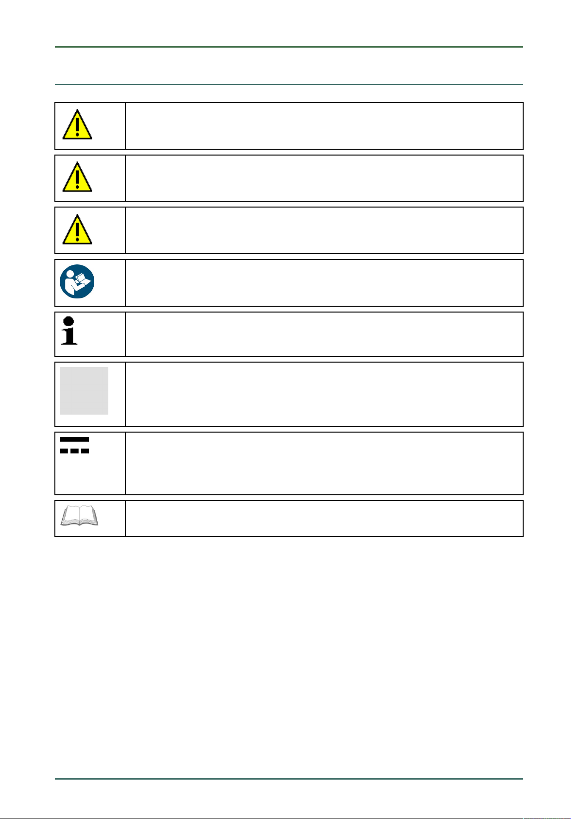
DANGER
Text parts marked in this way indicate an imminent dangerous situation which, if not avoided, will
lead to death or severe injuries.
WARNING
Text parts marked in this way indicate a potentially dangerous situation which, if not avoided, will
lead to death or severe injuries.
CAUTION
Text parts marked in this way indicate a potentially dangerous situation which, if not avoided, will
lead to minor or slight injuries if it is not avoided.
NOTICE
All texts labeled NOTICE refer to a hazard in the device or environment. Therefore, it is absolutely
necessary to observe the notes or instructions stored here.
About this Manual
Marking of Text Parts
NOTE
Texts marked with NOTE contain important and helpful information. It is recommended to
observe these texts.
Crossed out waste bin
This label indicates that the product must not be discarded as domestic waste.
The bar underneath the waste bin indicates whether the product was "placed on the market" after
August 13, 2005.
Direct current voltage
This label indicates a direct current voltage.
Direct current voltage means that the electrical voltage does not change over a longer period of
time.
Observe user manual
This label indicates that the user manual must always be read and always be available.
9
User Information
Safety Precautions
2 User Information
2.1 Safety Precautions
2.1.1 General Safety Precautions
• The PC VCI is intended for use on motor vehicles only. It is a precondition for the use of the PC
VCI that the user has knowledge of automotive technology and is therefore aware of the
sources of danger and risks in the workshop and on motor vehicles.
• Please read the entire user manual thoroughly and carefully before using the mega macs PC.
You can also find the user manual under
• All notes given in the individual sections of this user manual apply. The following measures
and safety precautions must also be followed.
• Furthermore, pay attention to all general instructions from labor inspectorates, trade
associations and vehicle manufacturers as well as all laws, legal ordinances and instructions
which have to be commonly obeyed by a repair shop.
mega macs PC
in the mega macs PC.
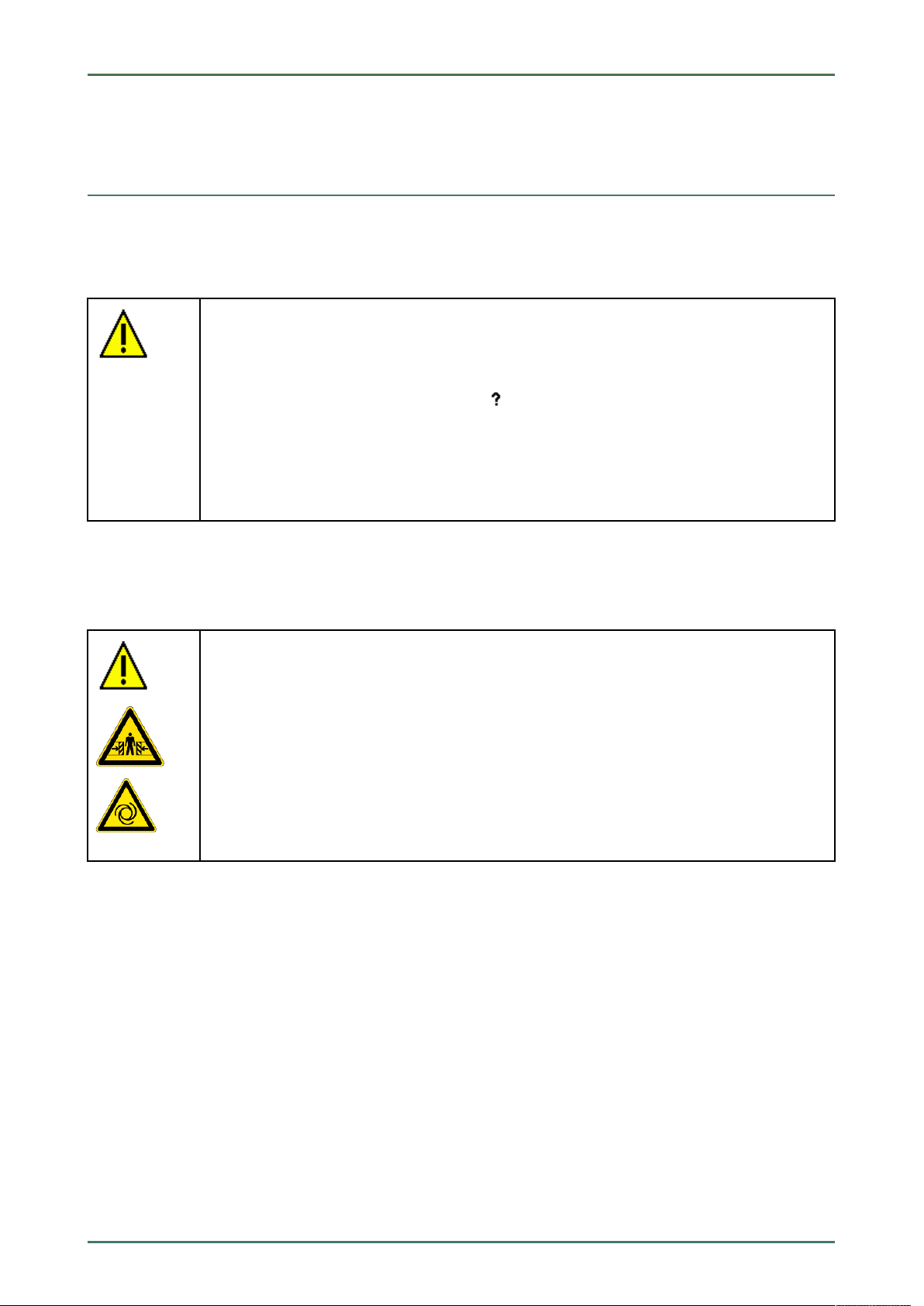
2.1.2 Safety Precautions – Risk of Injury
When working on the vehicle, there is a risk of injury through rotating parts or rolling of the
vehicle. Therefore regard the following:
• Prevent the vehicle from rolling.
• Additionally place gear selector lever of AT vehicles to park position.
• Deactivate the start/stop system to avoid an inadvertent engine startup.
• Connect the PC VCI to the vehicle only when engine is shut down.
• Do not reach into rotating components when engine is running.
• Do not run cables near rotating parts.
• Check the high-voltage parts for damage.
10
mega macs PC
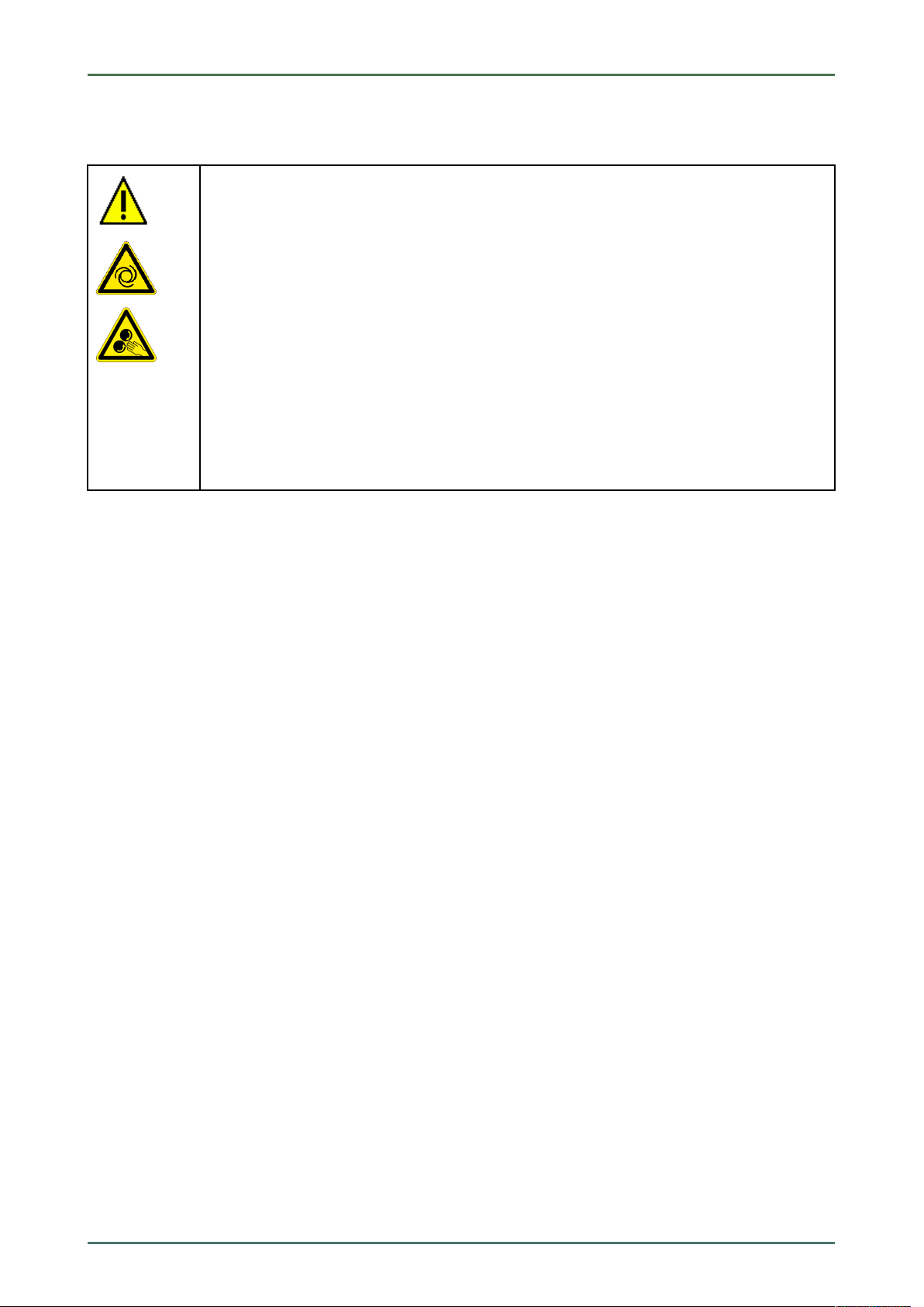
2.1.3 Safety Precautions for the PC VCI
Observe the following to avoid incorrect handling and injury to the user or destruction of the PC
VCI arising from this:
• Protect the PC VCI and the connecting cables from hot parts.
• Protect the PC VCI and the connecting cables from rotating parts.
• Regularly check connecting cables/accessory parts for damage (destruction of the PC VCI due
to short circuit).
• Connect the PC VCI exclusively according to user manual.
• Protect the PC VCI from fluids such as water, oil or gasoline. The PC VCI is not watertight.
• Protect the PC VCI from strong impacts and do not drop it.
• Do not open the PC VCI on your own. Only technicians authorized by Hella Gutmann are
allowed to open the PC VCI. Warranty and guarantee will be rendered void at any case of
unauthorized tampering of the device or if the protective seal is damaged.
• If the PC VCI is not working properly, contact Hella Gutmann or a Hella Gutmann trading
partner without delay.
User Information
Safety Precautions
11
User Information
Safety Precautions
2.1.4 Safety Precautions for High Voltage/Line Voltage
Very high voltages occur in electrical systems. Due to voltage flashover on damaged components,
such as marten damage or touching live components, the risk of electric shock is likely. High
voltage via the vehicle and line voltage via the building's mains supply can cause severe injury or
even death if adequate care is not taken. Therefore regard the following:
• Only use power supply cables with grounding contact.
• Only use a checked or the attached power cord.
• Always use the original cable set.
• Regularly check cables and adapters for damage.
• Perform any assembly work such as the connection of the PC VCI to the vehicle or the
replacement of components only when ignition is switched off.
• Do not touch live components when ignition is switched on.
mega macs PC
12

mega macs PC
2.1.5 Safety Precautions for Hybrid/Electric Vehicles
Very high tensions occur on hybrid and electric vehicles. Due to voltage flashover on damaged
components, such as marten damage or touching live components, the risk of electric shock is
likely. High voltage at or in the vehicle can lead to death in case of inattention. Therefore regard
the following:
• Only the following qualified employees are allowed to de-energize the high-voltage system:
– High-voltage technician
– Skilled electrician for predetermined operations – Hybrid or rather electric vehicles
– Skilled electrician
• Place warning signs and warning tapes.
• Check the high-voltage system and the high-voltage lines for damage (visual inspection!).
• De-energizing the high-voltage system:
– Switch off ignition.
– Disconnect the service disconnect plug.
– Remove the fuse.
• Securing the high-voltage system against re-activation:
– Withdraw the ignition key and keep it safe.
– Keep the service disconnect plug safe or secure the battery master switch against re-
activation.
– Insulate the battery master switch, the plug connections etc. with dummy plugs, covering
caps or insulating tape with the corresponding warning notice.
• Check the de-energized state with a voltage tester. Even with disconnected high-voltage
system, residual voltage can still be present.
• Ground and short-circuit the high-voltage system (necessary only if voltage is higher than
1000 V).
• Voltage below 1000 V: Cover the parts which are close to the system or which are energized e.
g. with insulating cloth, hoses or plastic coverings. Voltage higher than 1000 V: Cover the parts
with insulating plates/protective panels specially developed for this purpose so that sufficient
protection against contact to adjacent parts is ensured.
• Regard the following before re-energizing the high-voltage system:
– All tools and utilities are removed from the hybrid/electric vehicle.
– Remove the grounding and short circuit of the high-voltage system. Do not touch any of
the cables now.
– Attach the protective paneling that has been removed before.
– Remove the protective measures at the switching system.
User Information
Non-Liability
2.2 Non-Liability
2.2.1 Software
2.2.1.1 Safety-Relevant Software Modifications
The present device software provides numerous diagnostic and configuration functions. Some of these functions affect
the behavior of electronic components. These components also include components in safety-related vehicle systems,
13

User Information
Non-Liability
e.g., airbag or brakes. The following notes and instructions also apply to future updates and related software
extensions.
mega macs PC
2.2.1.2 Performing Safety-Relevant Software Modifications
• Work on safety-related areas, e.g. the occupant safety system and the brake system, is only allowed to be
performed if the user has read and accepted this note.
• The user of the diagnostic device must comply fully with all work steps and conditions given by the device and the
vehicle manufacturer, and follow the related instructions without fail.
• Diagnostic programs that make safety-related software modifications in the vehicle may and are only allowed to
be used if the related warning notes including the declaration given in the following are accepted without
reservation.
• It is imperative that the diagnostic program is used correctly, as programs, configurations, settings, and indicator
lamps can be deleted/cleared with it. These changes affect and modify safety-related data and electronic controls,
in particular safety systems.
2.2.1.3 Prohibition of Safety-Relevant Software Modifications
Changes or modifications to electronic controls and safety-related systems are not allowed to be made in the
following situations:
• The ECU is damaged and it is not possible to read out the data.
• The ECU and its allocation cannot be read out unambiguously.
• Reading out is not possible due to data loss.
• The user does not have the related training and knowledge necessary.
In these cases the user is not allowed to change programs, configurations, or to make other changes in the safety
system. To avoid any danger, the user has to contact an authorized dealer instantly. Only an authorized dealer can
guarantee the safe function of vehicle electronics together with the factory.
2.2.1.4 Waiver of the Use of Safety-Relevant Software Modifications
The user undertakes not to use any safety-related software functions if one of the following conditions arise:
• There are doubts about the specialized skills of third parties to use these functions.
• The user does not have the prescribed training qualifications.
• There are doubts about the correct function of the safety-related software engagement.
• The device is transferred to a third party. Hella Gutmann Solutions GmbH is unaware of this fact and has not
authorized the third party to use the diagnostic program.
2.2.2 Non-Liability
2.2.2.1 Data and Information
The information in the database of the diagnostic program has been compiled based on automotive and importer
information. Great care was taken to ensure the correctness of the information. The Hella Gutmann Solutions GmbH
accepts no liability for any mistakes and the resulting consequences. This statement also applies to the use of data
and information that are found to be incorrect or that were incorrectly displayed, also to errors that occurred
inadvertently during compilation of the data.
14

mega macs PC
User Information
Non-Liability
2.2.2.2 Burden of Proof on the User
The burden of proof is on the user of the device, that he has paid attention to technical explanations, notes on
operation, equipment care as well as maintenance and safety without exception.
2.2.3 Data Protection
The Customer agrees that its data may be stored for implementing and executing the contractual relationship and that
technical data may be stored for performing data audits relevant to data security, statistical analysis and quality
control. The technical data shall be stored separately from personal data and shared only with our contractors. We are
obliged to treat all customer data that we receive confidentially. We may only disclose customer data if statutory
provisions permit or require such disclosure or if the Customer has agreed.
2.2.4 Documentation
The notes given in the device describe the most common fault reasons. However, there are often further reasons for
existing faults, which cannot be listed here, or there are further sources of error, which are unknown yet. The Hella
Gutmann Solutions GmbH is not liable for failed or unnecessary repair work.
The Hella Gutmann Solutions GmbH does not accept any liability for the usage of data and information that are found
to be incorrect or that were incorrectly displayed, also for errors that occurred inadvertently during the compilation of
the data.
Notwithstanding the above, the Hella Gutmann Solutions GmbH does not accept any liability for any losses in relation
to loss of profit, goodwill, or any other loss, including financial loss.
Hella Gutmann Solutions GmbH accepts no liability for damages or operating trouble resulting from failure to observe
the "mega macs" user manual and the special safety precautions.
The burden of proof is on the user of the device, that he has paid attention to technical explanations, notes on
operation, equipment care as well as maintenance and safety without exception.
15
Device Description mega macs PC
Delivery Contents
3 Device Description
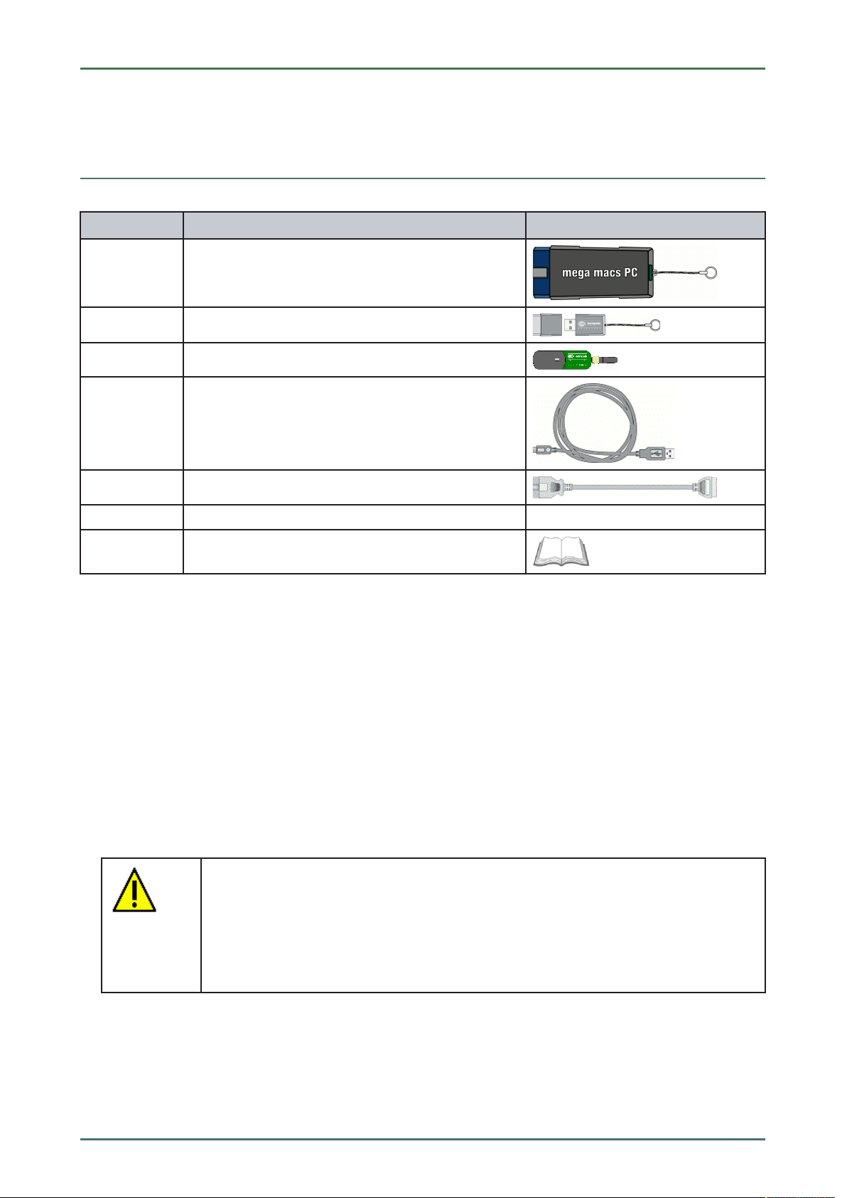
3.1 Delivery Contents
QQuuaannttiittyy DDeessiiggnnaattiioonn
1 PC VCI
1
1
1
1
1
1
Pen drive for installing the mega macs PC
Bluetooth® adapter
USB cable for connecting the PC VCI to the PC
OBD cable extension 0.3 m (optional)
HGS data carrier
Quick Start Guide
3.1.1 Checking Delivery Contents
Please check the delivery contents upon receiving your device so that complaints can be issued immediately regarding
any potential damage.
Proceed as follows to check the delivery contents:
1. Open the package supplied and check for completeness based on the delivery slip.
Should you identify any damage to the package, then open the package in the presence of the delivery service and
check the PC VCI for hidden damage. Any transport damage to the package supplied and damage to the PC VCI
shall be registered in a damage report by the delivery service.
2. Take the PC VCI out of the packaging.
CAUTION
Danger of short circuit due to loose parts in or on the PC VCI
Danger of destruction of the PC VCI and/or the automotive electronics
Never put the PC VCI into operation if you suspect that there are loose parts in or at the
module. In this case please contact the Hella Gutmann repair service or a Hella Gutmann
trading partner immediately.
3. Check the PC VCI for mechanical damage and shake it lightly to ensure that there are no loose parts inside.
16
mega macs PC Device Description
Intended Use
3.2 Intended Use
The mega macs PC software and the PC VCI are systems used for detecting and rectifying faults in automotive
electronic systems.
It uses a diagnostic interface to establish a connection to the automotive electronics and to provide access to
descriptions of the vehicle system. A lot of this data is transferred to the PC directly via an Internet connection from
the Hella Gutmann diagnostic database. Therefore, the PC should be permanently online.
The mega macs PC software is not suitable for repairing electrical machines and devices or home electrics. Diagnostic
devices from other manufacturers will not be supported.
If the mega macs PC software and the PC VCI is used in a way not authorized by Hella Gutmann the protection of the
device may be influenced.
The PC VCI is intended for industrial use. Outside of industrial environments, e.g., in commercial areas or in the centre
of a town, radio interference suppression measures may need to be taken.
3.3 Using the Bluetooth® Function
The terms of use of the Bluetooth® function may be restricted or prohibited through law or corresponding legal
regulations in certain countries.
Observe the provisions in force in the respective country before using the Bluetooth® function.
3.4 Range of Functions
The range of functions of the mega macs PC software depends on the country, the licenses acquired, and/or the
optionally available hardware. This documentation may therefore describe functions that are not available on the
individual device. Missing functions can be enabled by acquiring a corresponding license subject to charge and/or
additional hardware.
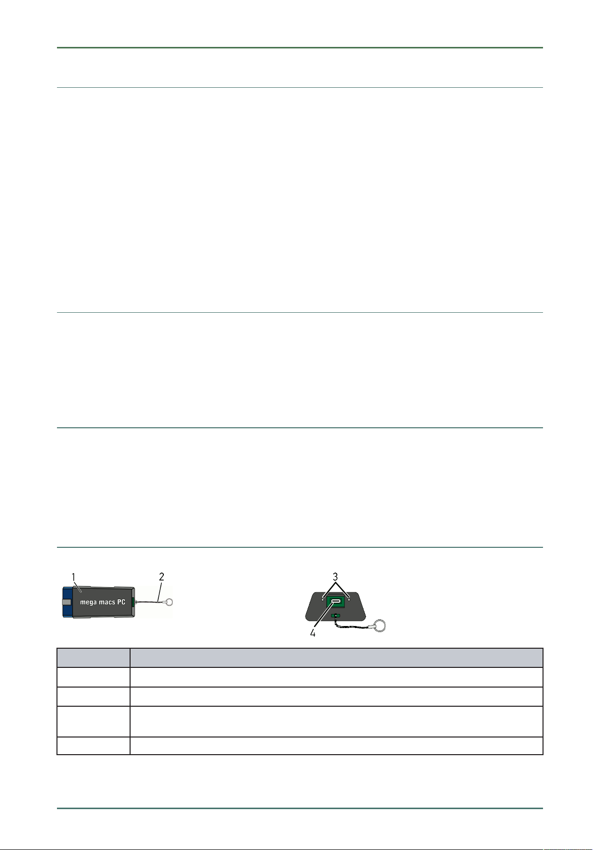
3.5 Connectors
DDeessiiggnnaattiioonn
1
2
3
4
PC VCI for diagnostic connection to the vehicle
Retaining strap for mounting e.g. a lanyard
Green and blue indicator lamp (LED)
The indicator lights show the operating state of the PC VCI.
Micro USB interface for USB cable to USB interface of the PC
17

Device Description mega macs PC
Connectors
3.5.1 Meaning of the Flashing Frequencies
SSttaattuuss ddiissppllaayy
BBlluuee LLEEDD
LED switched off. LED switched off.
LED flashes quickly (1x per sec.). LED switched off.
LED flashes slowly (every 3
sec.).
LED flashes slowly (every 3
sec.).
LED switched off.
LED permanently on with
regular brief interruptions.
GGrreeeenn LLEEDD
MMeeaanniinngg
• Software inactive/faulty.
• No voltage present.
• PC VCI faulty.
• Update failed.
• Update invalid.
• PC VCI faulty.
• Update failed.
• Update invalid.
• PC VCI faulty.
PC VCI ready for operation.
18

mega macs PC
Installation of the Hella Gutmann Drivers Package
System Requirements of Hella Gutmann Drivers
4 Installation of the Hella Gutmann Drivers Package
4.1 System Requirements of Hella Gutmann Drivers
• Windows 7 SP1 or higher
• Windows administrator rights
4.2 Installation of the Hella Gutmann Drivers Package
To obtain all the data about the related vehicle provided by Hella Gutmann, the device requires a permanent online
connection and the installed driver package Hella Gutmann Drivers. To keep the connection costs down, Hella
Gutmann recommends a DSL connection and a flat rate.
1. Install the Hella Gutmann Drivers on the office or repair shop PC.
The driver package Hella Gutmann Drivers program is on the supplied HGS data carrier.
2. Connect the device to a web-compatible PC.
Once the connection symbol
been set up successfully and is active.
in the top symbol bar changes from black to green, the online connection has
19

Contents of the mega macs PC Software
Diagnostic Functions
mega macs PC
5 Contents of the mega macs PC Software
5.1 Diagnostic Functions
• Reading/deleting trouble codes
• Parameter readout
• Actuator tests
• Service reset
• Basic settings
• Codings
• Test function
5.2 Additional Functions and Contents (Depending on the
License Type)
• Vehicle information, e.g.:
– Timing belt data
– Service data
– Recall campaigns
• 2 updates per year, e.g.:
– Diversification of the existing functions by new vehicle models
20

mega macs PC
Supported Operating Systems for the mega macs PC
Installation of the mega macs PC
6 Installation of the mega macs PC
6.1 Supported Operating Systems for the mega macs PC
• Microsoft Windows Vista
• Microsoft Windows 7/8
6.2 System Requirements for the mega macs PC
• at least 512 MB free internal memory
• at least 2 GB free hard drive space
• at least 1 free USB port at the PC
• Screen resolution at least 800 x 600
6.3 Installing the mega macs PC Software
An installation wizard guides you through the necessary installation steps.
Proceed as follows to install the mega macs PC software:
1. Switch on your PC.
2. Plug in the supplied pen drive (2) into the USB port of the PC.
The USB drive mega macs PC opens automatically.
3. Click >Open folder< and start the file mega_macs_pc.exe.
• You can also open the USB drive as follows: Start > My Computer > mega macs PC.
The mega macs PC Setup window appears.
4. Select the required language and click >OK<.
The selection will be saved automatically.
5. Click >Next<.
A selection window appears. A target directory for the mega macs PC software files is already suggested. If you
wish to have another target directory, you can use the >Search< function to select a suitable directory. At the end
of installation, the files will be copied into the selected target directory.
6. Click >Next<.
7. Click >Install<.
Installation is started.
8. Wait until installation is finished.
9. Click >Finish<.
A link to the mega macs PC is automatically created on the desktop.
10. Disconnect the pen drive.
Installation of the mega macs PC software is complete now.
21
Putting the mega macs PC into Operation
Connection to the PC VCI
mega macs PC
7 Putting the mega macs PC into Operation
This section gives a description of how to switch on and off the mega macs PC software as well as all the necessary
steps for the first use of the mega macs PC software.
7.1 Connection to the PC VCI
NOTE
The PC VCI must always be connected via Bluetooth® to the PC on which the mega macs PC
software is used.
The PC VCI is a regular feature of the mega macs PC software. The PC VCI contains software components. Various
functions of the mega macs PC software therefore require a connection to the PC VCI.
7.2 Executing the mega macs PC Software
NOTE
When putting the device into operation for the first time and after every software update, you need
to confirm the general terms and conditions (GTC) of the Hella Gutmann Solutions GmbH.
Otherwise, certain device functions will be unavailable.
NOTE
Upon the first start-up of the device, you must couple the mega macs PC software with the PC
VCI. This requires the mega macs PC software to be connected to the PC VCI via USB cable. A
Bluetooth® connection is sufficient when starting up in the future.
Proceed as follows to execute the mega macs PC software:
1. Connect the PC and the PC VCI with the USB cable.
2. Go to Start > All programs > Hella Gutmann Solutions > mega macs PC and select > mega macs PC.
The mega macs PC can also be executed as follows:
• Windows 8: Click on the mega macs PC symbol on the start screen.
• Windows 7 and lower: Click on the mega macs PC shortcut on the desktop.
The mega macs PC software will be started.
The GTCs appear.
3. Read the GTCs and confirm them at the end of the text.
A user selection window appears. The user name is saved for all data stored in the Car History. This enables
quicker identification of the mechanic who performed the repair work if a query is subsequently made.
4. Double-click
5. Enter the user name.
6. Confirm your entry with
7. Activate the Stay logged in check box if necessary.
If the Stay logged in check box is activated, you will not need to select a user name when switching on in the
future.
8. Confirm your entry with
The input will be saved automatically.
9. Disconnect the USB cable from PC VCI and PC.
22
.
.
.

mega macs PC
10. Insert the Bluetooth® adapter into the USB port of the PC.
Once the PC recognized the Bluetooth® adapter the LED becomes blue.
The main menu appears.
Now you can work with the mega macs PC software.
Putting the mega macs PC into Operation
7.3 License Release
NOTE
In order to use the full scope of the purchased licenses you need to connect the mega macs PC
software to the HGS server prior to the first start-up.
Proceed as follows to connect the mega macs PC software with the HGS server:
1. Select Contracts under > Settings in the main menu.
2. Select >License<.
3. Call up My licenses with
Data download is in progress. Purchased licenses are displayed.
4. Start the mega macs PC software again.
Now you can work with the mega macs PC software.
.
License Release
7.4 Closing the mega macs PC Software
Proceed as follows to close the mega macs PC software:
1. Close the mega macs PC software with
2. Observe the confirmation prompt.
3. Close the mega macs PC software with
The mega macs PC software will be closed.
.
. Abort the procedure with .
23

Installation of the HGS PassThru Software
Provision of HGS PassThru
mega macs PC
8 Installation of the HGS PassThru Software
8.1 Provision of HGS PassThru
Since 2010, the Euro 5 standard has been applicable for all new vehicles. It regulates, among other things, the typeapproval of vehicles with regard to emissions. With the Euro 5 standard, manufacturers are obligated to provide
independent repairers with unrestricted Internet access to all information relating to the maintenance and repair of the
vehicles.
Only Euro 5-capable devices may be used to to program the ECUs. HGS PassThru is an interface used to install the
latest software version from the online portal of the manufacturer on the vehicle ECU. The PassThru function is an
add-on and does not replace the diagnostic procedure. Here, Hella Gutmann establishes a direct communication
between the manufacturer's OEM server (Original Equipment Manufacturer) and the vehicle.
Provision of the software varies depending on the manufacturer. The following options are available:
• Download the PC software
• Request the PC software on CD or DVD
• Online solutions
Here charges may accrue depending on the manufacturer e.g. for:
• Registration
• Licenses
• Software
The software content (scope of information and function) varies depending on the manufacturer. Some manufacturers
provide the legally required functions and information only, whereas others provide additional data.
8.2 Supported Operating Systems for HGS PassThru
• at least Microsoft Windows 7 (32/64 bit)
8.3 System Requirements for HGS PassThru Driver
Hella Gutmann requires the following for installation of the HGS PassThru driver:
• at least 2 GB free internal memory
• at least 40 GB free hard disc space
• at least 1 free 2.0 USB port on the laptop/tablet
• web-compatible laptop or tablet
8.4 Installation of the HGS PassThru Software
An installation wizard guides you through the necessary installation steps.
Proceed as follows to install the HGS PassThru software:
1. Switch on the laptop/tablet.
2. Call up the website of Hella Gutmann.
3. Select WORKSHOP SOLUTIONS > SERVICE > PassThru.
24

mega macs PC
Installation of the HGS PassThru Software
Installation of the HGS PassThru Software
4. Select DOWNLOADS > Software – PassThru.
The window HGS PassThru Setup is displayed.
5. Save the PassThru setup.exe with >Save file<.
A target directory is suggested for the files of the PassThru setup.exe. If you wish to have another target directory
then select a suitable directory. At the end of installation, the files will be copied into the selected target directory.
6. Save the PassThru setup.exe with >Save<.
The PassThru setup.exe will be saved in the target directory.
7. Click the PassThru setup.exe in the target directory.
The window HGS PassThru Setup is displayed.
8. Select the requested language with
.
9. Confirm the selection with >OK<.
The selection is saved automatically. The setup wizard of HGS PassThru is displayed.
10. Click >Next<.
The general terms and conditions (GTCs) appear.
11. Read the GTCs and confirm them at the end of the text.
12. Click >Next<.
Select a product to be able to install the HGS PassThru Setup software successfully.
13. Select >HGS VCI<.
14. Install the product with >Install<.
Installation is started.
15. Wait until installation is finished.
16. Click >Finish<.
A link to HGS PassThru will be automatically created on the desktop.
Installation of the HGS PassThru software is complete now.
25
Initial Start-Up of the HGS PassThru Software
Preconditions for Initial Start-Up of HGS PassThru
mega macs PC
9 Initial Start-Up of the HGS PassThru Software
This section describes how the HGS PassThru software is used.
9.1 Preconditions for Initial Start-Up of HGS PassThru
• Voltage supply of device and laptop or tablet through mains supply and mains cable is ensured.
• Laptop or tablet is booted.
• Laptop or tablet available for connecting vehicle to the Internet
• HGS PassThru file correctly installed on laptop or tablet.
• Admin rights available.
• Latest Java version installed.
• Stable Internet connection
• All processes/programs that have been started or are running in the background are closed.
9.2 Running the HGS PassThru Software
CAUTION
Pay attention that the voltage supply during the entire procedure is no lower than 12 V.
A voltage drop may lead to the abortion of the download and the ECU may be damaged.
The old software version of the ECU cannot be re-established if an update is intended.
Proceed as follows to run the HGS Pass Thru software:
1. Select Applications > PassThru in the main menu.
The disclaimer is displayed.
2. Read the disclaimer and confirm it at the end of the text.
The PassThru function is active.
3. Insert the USB cable into the USB connection of the PC VCI.
CAUTION
Pulling off of the PC VCI when actuating the clutch
Risk of injury or material damage
Proceed as follows before starting:
1. Apply the parking brake.
2. No gear is engaged.
3. Regard the window with infos and instructions.
NOTICE
Short circuit and voltage peaks when connecting the PC VCI
Danger of destruction of automotive electronics
Switch off ignition before connecting the PC VCI to the vehicle.
4. Insert the PC VCI into the vehicle's diagnostic interface.
Both LEDs of the PC VCI flash. The PC VCI is ready for operation.
26

mega macs PC
Initial Start-Up of the HGS PassThru Software
Running the HGS PassThru Software
5. Insert the USB cable into the USB port of the laptop/tablet.
Connection is established. Laptop/tablet is connected to the vehicle via HGS VCI.
6. Switch on the vehicle ignition.
7. Observe the manufacturer's specifications.
8. Select Start > All Programs > Hella Gutmann Solutions > HGS PassThru communication.
Alternatively you can run the HGS PassThru software as follows.
• Windows 7: Select the HGS PassThru shortcut in the desktop.
9. Select the requested language.
10. Start the communication test with >Start test<.
The communication test is started. Connection between laptop/tablet and HGS VCI is tested.
The connection between laptop/tablet and HGS VCI is active if the left row of arrows is green.
The connection between HGS VCI and vehicle is tested afterwards.
The connection between HGS VCI and vehicle is active if the right row of arrows is green.
The connection between laptop/tablet and vehicle via HGS VCI has been successfully established now.
11. Finish the communication test with >Finish<.
12. Call up the requested manufacturer website online with the laptop/tablet.
13. Follow the instructions on the manufacturer portal.
14. Select PassThru (HGS VCI) of Hella Gutmann.
27

Configuring the mega macs PC
Setting company data
10 Configuring the mega macs PC
Configure all interfaces and functions under >Settings< in the main menu.
10.1 Setting company data
Enter the company data that shall appear on the hard-copy printout, e.g.:
• Company address
• Fax number
• Homepage
10.1.1 Entering Company Data
Proceed as follows to enter the company data:
mega macs PC
1. Select Company under > Settings in the main menu.
2. Select >Company data<.
3. Open the virtual keypad under Company name with
4. Enter the company name.
5. Confirm your entry with
The input will be saved automatically.
6. Repeat steps 3-5 for further entries.
.
.
10.1.2 User name
10.1.2.1 Entering the User Name
Here you can manage the different users.
The respective user name is saved for all data stored in the Car History. This enables quicker identification of the
mechanic who performed the repair work if a query is subsequently made.
Proceed as follows to enter the user name:
1. Select Company under > Settings in the main menu.
2. Select >User<.
3. Open the virtual keypad with
4. Enter the user name.
5. Confirm your entry with
The input will be saved automatically.
.
.
10.1.2.2 Assigning a Password
Here you have the option to assign passwords to the users.
The assigned password must be entered when selecting the user.
Proceed as follows to assign a password to a user:
1. Select Company under > Settings in the main menu.
28

mega macs PC
2. Select >User<.
3. Selected the requested user name.
Configuring the mega macs PC
Setting company data
4. Open the virtual keypad under Password (optional) with
5. Enter the requested password.
6. Confirm your input with
The input will be saved automatically.
.
10.1.2.3 Deleting the Password
Proceed as follows to delete the password:
1. Select Company under > Settings in the main menu.
2. Select >User<.
3. Selected the requested user name with assigned password.
4. Delete the password under Password (optional) with
5. Observe the confirmation prompt.
6. Confirm the confirmation prompt with
Password will be deleted.
.
.
.
10.1.2.4 Deleting the User Name
Proceed as follows to delete the user name:
1. Select Company under > Settings in the main menu.
2. Select >User<.
3. Select the required user name.
4. Delete the user name with
5. Observe the confirmation prompt.
6. Confirm the confirmation prompt with
The user name is deleted.
.
.
10.1.2.5 Activating the Car History
Proceed as follows to activate the Car History:
NOTE
Only if the check box Car History active is activated the data records will be saved automatically
in the Car History.
1. Select Company under > Settings in the main menu.
2. Select >User<.
3. Activate the check box Car History active.
Now data records will be saved in the Car History.
29
Configuring the mega macs PC
Update of the mega macs PC and PC VCI Software
mega macs PC
10.1.2.6 Setting Up Password Protection
Introduction of the General Data Protection Regulation (GDPR) of the European Union on 25 May 2018 includes the
requirement to ensure better protection for customer-related data in devices and equipment.
To prevent access to our diagnostic devices by third parties, we have integrated the function Password protection.
NOTE
Due to legal requirements concerning third party access, the device can only be reactivated via the
function >Starting the factory reset< or the Technical Hotline of Hella-Gutmann Solutions. In
this case the personal data and the Car History will be cleared and might possibly not be restored.
Proceed as follows to set up the password protection:
1. Select Company under > Settings in the main menu.
2. Select >User<.
3. Call up Password management with
NOTE
The length of the password must not exceed 10 characters.
4. Enter a password and confirm by entering it again.
5. Observe the warning notice and confirm.
The device can now be accessed only with the selected password.
.
10.1.2.7 Creating Cost Estimates
Here you can enter the base values for the cost estimate.
You can enter 3 different hourly rates (net) and one VAT rate. These values are used to calculate the total amount of
the work to be done.
Proceed as follows to enter the basic values in the cost estimate:
1. Select Company under > Settings in the main menu.
2. Select >Cost estimate<.
3. Open the virtual keypad under Hourly rate 1 (Net in EUR) with
4. Enter the required hourly rate.
.
5. Confirm your input with
The input will be saved automatically.
6. Repeat steps 3 to 5 for further entries.
.
10.2 Update of the mega macs PC and PC VCI Software
Here you can perform the updates of the software the PC VCI. Various system parameters are also displayed, e.g.:
• Package version
• Module type (ID)
• Software version
Hella Gutmann Solutions supplies customers with regular software updates. The update is subject to charge. These
updates contain new vehicle systems as well as technical modifications and improvements. We recommend keeping
your software up to date.
30

mega macs PC
Update of the mega macs PC and PC VCI Software
Configuring the mega macs PC
10.2.1 Preconditions for an Update
Ensure the following to perform updates:
• The mega macs PC software is installed on a web-compatible PC.
• The PC VCI is connected to a web-compatible PC through USB cable or Bluetooth®.
• A Bluetooth®-compatible PC or Bluetooth® adapter is plugged into the PC.
• The corresponding licenses are activated by Hella Gutmann.
• The driver package Hella Gutmann Drivers is installed on the PC.
• Voltage supply of PC and PC VCI is guaranteed.
10.2.2 Calling Up System Information
Here you will find all information required for the identification of the mega macs PC software.
Proceed as follows to call up system information:
1. Select Update under > Settings in the main menu.
2. Select >System<.
An info window appears.
Here you can find information including the software and hardware version and the device number.
10.2.3 Setting the Language
Here you can set the language version if the software is multilingual. After having set the language, the update will be
installed in this language.
Proceed as follows to set the language:
1. Select Update under > Settings in the main menu.
2. Select >System<.
3. Open the list under Language setting with
The compilation of languages depends on the prevailing software.
4. Select the requested language.
The selection will be saved automatically.
.
10.2.4 Starting the Test
Check the present software for incorrect or missing files here.
Proceed as follows to start the test:
1. Select Update under > Settings in the main menu.
2. Select >System<.
3. Open the list under Step with
4. Select >Check<.
5. Start the check with
Installation is being checked.
The delivered list after completion of the installation test must not include an incorrect file.
The message Device software OK appears if the present software is OK.
.
.
31

Configuring the mega macs PC
Update of the mega macs PC and PC VCI Software
6. Should the list nevertheless include incorrect files, start the update again.
10.2.5 Starting the Software Update
Start the software updates here.
Proceed as follows to start the software update:
1. Select Update under > Settings in the main menu.
2. Select >System<.
mega macs PC
3. Open the list under Step with
4. Select >Update<.
NOTICE
Insufficient voltage supply
System data loss
Do not switch off the PC and the PC VCI during the software update and do not disconnect both
from voltage supply.
Ensure sufficient voltage supply.
5. Start Update with
The device searches for a new update that will then be downloaded and installed.
The mega macs PC software will be finished automatically upon a successful software update. The installation will be
checked automatically after startup.
.
.
10.2.6 Calling up PC VCI Information
Here you will find all information required for the identification of the PC VCI.
Proceed as follows to call up the PC VCI information:
1. Select Update under > Settings in the main menu.
2. Select >PC VCI<.
An info window appears.
This menu provides the software and hardware version and the module type of the PC VCI.
10.2.7 PC VCI Update
NOTICE
Insufficient voltage supply
System data loss
Do not switch off the PC and the PC VCI during the PC VCI update and do not disconnect both from
voltage supply.
Ensure sufficient voltage supply.
Proceed as follows to start the PC VCI update:
1. Select Update under > Settings in the main menu.
32

mega macs PC
2. Select >PC VCI<.
CAUTION
Pulling off of the PC VCI when actuating the clutch
Risk of injury or material damage
Proceed as follows before starting:
1. Apply the parking brake.
2. No gear is engaged.
3. Regard the window with infos and instructions.
NOTICE
Short circuit and voltage peaks when connecting the PC VCI
Danger of destruction of automotive electronics
Switch off ignition before connecting the PC VCI to the vehicle.
3. Connect the PC VCI to the vehicle's diagnostic connector.
Configuring the mega macs PC
Configuring the Interfaces
Alternatively, you can ensure voltage supply via USB cable.
Both LEDs of the PC VCI flash. The PC VCI is ready for operation.
4. Start the PC VCI update with
5. Regard the window with infos and instructions.
6. Confirm the window with infos and instructions with
The PC VCI update will be started. Data is copied from the mega macs PC software to PC VCI.
The message PC VCI update successfully done. appears if the update was successful.
.
.
10.3 Configuring the Interfaces
Here you can configure the interfaces for the printer and the BPC-Tool.
All interfaces of the mega macs PC software are configured under Settings > Interfaces.
10.3.1 Configuring the BPC-Tool
10.3.1.1 Searching for a BPC-Tool
Proceed as follows to search for a BPC-Tool:
1. Switch on the BPC-Tool and connect it with the mega macs PC software (see operating instructions of the BPCTool).
2. Select Interfaces under > Settings in the main menu.
3. Select >BPC<.
4. Search for a BPC-Tool with
5. Observe the info window.
6. Confirm the info window with
The connection to the BPC-Tool is established.
Once the connection from the mega macs PC software to the BPC-Tool has been set up successfully, a drop-down
list of the BPC-Tools that have been found is displayed.
.
.
33

Configuring the mega macs PC
Configuring the Interfaces
7. Select the required BPC-Tool.
The selection will be saved automatically.
The selected BPC-Tool address is displayed in the field BPC address.
mega macs PC
10.3.1.2 Deactivating the BPC-Tool Connection and Deleting the Assignment
Here you can deactivate the BPC-Tool connection and delete the assignment.
Proceed as follows to deactivate the BPC-Tool connection and delete the assignment:
1. Select Interfaces under > Settings in the main menu.
2. Select >BPC<.
3. Deactivate the connection to the BPC-Tool and delete the assignment with
4. Observe the confirmation prompt.
5. Confirm the confirmation prompt with
The BPC-Tool connection is deactivated and the assignment is deleted.
.
10.3.1.3 Starting a BPC-Tool Update
Proceed as follows to start the BPC Tool update:
1. Connect the BPC-Tool to the battery.
2. Select Interfaces under > Settings in the main menu.
3. Select >BPC<.
NOTICE
Insufficient voltage supply
System data loss
Do not switch off the PC and the BPC-Tool during the update and do not disconnect both from
voltage supply.
Ensure sufficient voltage supply.
.
4. Start BPC-Tool update with
5. Regard the window with infos and instructions.
6. Confirm the window with infos and instructions with
Update of the BPC-Tool will start. The device searches for a new update that will then be downloaded and
installed.
The message BPC-Tool update successful. appears if the update was successful.
.
.
10.3.1.4 Calling up System Information for the BPC-Tool
Here you can find all information required for identification of the BPC-Tool.
Proceed as follows to call up system information of the BPC-Tool:
1. Select Interfaces under > Settings in the main menu.
2. Select >BPC<.
3. Call up System information with
An info window appears.
Here you can find information including the product name, the product ID and the operating system.
34
.

mega macs PC
Configuring the mega macs PC
Setting the Country
10.3.2 Setting Up the Printer
10.3.2.1 Printing with Standard PC Printer
Here you can set the standard printer for printing with the PC on which the mega macs PC software is installed.
For this, the mega macs PC software must forward the data to be printed to the Hella Gutmann Drivers. Then the
Hella Gutmann Drivers sends the data to the standard printer of the system.
Proceed as follows to print out results with the standard printer:
1. Select Interfaces under > Settings in the main menu.
2. Select >Printer<.
3. Open a list under Interface with
4. Select >Gutmann Portal<.
The selection will be saved automatically.
5. Use
The margins are set ex works to 15 mm.
6. Delete the number set ex works with
7. Enter the requested height of the margins in mm.
8. Confirm your entry with
The input will be saved automatically.
9. Repeat steps 5-8 for further entries.
10. Where necessary, activate the check box Blank out company logo to print out results without the company logo
of Hella Gutmann.
This function enables hard-copy printouts on printed paper.
Now you can start printing via PC.
to open the virtual keypad under top (mm).
.
.
or where necessary.
10.4 Setting the Country
Configure the following data here:
• Language setting
• Country setting
• Currency
10.4.1 Setting the Language Option
Here you can set the language if the software is multilingual (optional).
Proceed as follows to set the language:
1. Select Country under > Settings in the main menu.
2. Open the list under Language setting with
The compilation of languages depends on the prevailing software.
3. Select the requested language.
4. Regard the window with infos and instructions.
5. Close the window with infos and instructions with
The mega macs PC software will be finished automatically. The language setting will be saved automatically.
.
.
35

Configuring the mega macs PC
Setting Units
6. Execute the mega macs PC software again.
mega macs PC
7. Confirm the user selection window with
The main menu appears.
.
10.4.2 Making Country Settings
Make your country settings here.
The country version contains certain information, such as the print format for letters.
Proceed as follows to make the country settings:
1. Select Country under > Settings in the main menu.
2. Open the list under County with
The compilation of countries depends on the prevailing software.
3. Select the country to the corresponding language.
The selection will be saved automatically.
.
10.4.3 Setting the Currency
Here you can set the prevailing currency.
Proceed as follows to set the currency:
1. Select Country under > Settings in the main menu.
2. Open the list under Currency with
The compilation of currencies depends on the prevailing software.
3. Select the requested currency.
The selection will be saved automatically.
.
10.5 Setting Units
Adapt physical units to the prevailing regional metric system here.
10.5.1 Assigning Units
Proceed as follows to assign regional units to physical sizes:
1. Select Units under > Settings in the main menu.
2. Open a list under the requested unit with
3. Select the requested unit.
The selection will be saved automatically.
36
.

mega macs PC
10.6 Configuring Miscellaneous
Configure the following data here:
• Other stipulations
• Car History
• Resolution
10.6.1 Configuring Other Matters
Here you can configure settings such as:
• Tips
• Demo mode
• Order management
Configuring the mega macs PC
Configuring Miscellaneous
10.6.1.1 Setting the Demo Mode
Here you can set whether the device shall give predetermined values during the vehicle communication. This setting is
mainly intended for marketing and sales presentations.
NOTE
In the course of vehicle diagnostics the demo mode must be switched off. Otherwise the device
will deliver predetermined diagnostic results and no real values.
Proceed as follows to set the demo mode:
1. Select Miscellaneous under > Settings in the main menu.
2. Select >Miscellaneous<.
3. Open the list under Demo mode with
4. Select >on< or >off<.
Demo mode is switched off or on.
.
10.6.1.2 Setting Tips
Here you can activate or deactivate additional information on different functions.
Proceed as follows to set the indication of tips:
1. Select Miscellaneous under > Settings in the main menu.
2. Select >Miscellaneous<.
3. Open the list under Tips with
4. Select >on< or >off<.
Tips are switched off or on. The selection will be saved automatically.
.
10.6.1.3 Configuring Order Management
Here you can set the data exchange between the mega macs PC software and the order management.
Proceed as follows to set the order management:
1. Select Miscellaneous under > Settings in the main menu.
2. Select >Miscellaneous<.
37

Configuring the mega macs PC
Configuring Miscellaneous
mega macs PC
3. Open a list under Order management with
4. Select >on< or >off<.
Order management is switched off or on. The selection will be saved automatically.
.
10.6.1.4 Performing a Factory Reset
Here you can reset the mega macs PC software to factory settings.
The following data and files will be reset to the state of delivery if you do the factory reset:
• Data stored in the Car History
• Downloaded files such as wiring diagrams or service schedules
• User data such as company data
The following functions will be also modified or deleted:
• IP address mode
• Telekom HotSpot
• Bluetooth® MAC address
• asanetwork
• Display settings
• Confirmation of General terms and conditions
• Printer settings
Proceed as follows to perform a factory reset:
1. Select Miscellaneous under > Settings in the main menu.
2. Select >Miscellaneous<.
3. Start Factory reset with
4. Observe the confirmation prompt.
5. Confirm the confirmation prompt with
The mega macs PC software will be automatically reset to the condition at delivery.
.
.
10.6.2 Configuring the Car History
This menu provides the diagnostic results to the present vehicle from the functions >Trouble codes<, >Parameters<,
>Basic settings< and >Codings. This has the following advantages:
• You can evaluate the diagnostic results later.
• Compare previously performed diagnostics to present diagnostic results.
• You can show the customer the diagnostic results without needing to reconnect the vehicle.
10.6.2.1 Automatic Car History Transfer
If you have selected the option Automatic Car History Transfer, the data saved in the Car History will be automatically transferred to Hella Gutmann.
Proceed as follows to transfer the Car History automatically:
1. Select Miscellaneous under > Settings in the main menu.
2. Select >Car History<.
3. Open a list under Automatic Car History Transfer with
38
.

mega macs PC
4. Select >on< or >off<.
The selection will be saved automatically.
Configuring the mega macs PC
Configuring Miscellaneous
10.6.2.2 Manual Parameter Management
Here you can select whether the device offers to delete existing parameter records in the Car History if there is not
enough memory space.
Proceed as follows to manage the parameters manually:
1. Select Miscellaneous under > Settings in the main menu.
2. Select >Car History<.
3. Open a list under Administrating parameters manually with
4. Select >on< or >off<.
NOTE
If >on< is selected, you can determine existing measurements in the Car History to be deleted.
If >off< is selected, the device will automatically delete the oldest entries in the Car History.
The selection will be saved automatically.
10.6.2.3 Sending the Car History
Here you can send the Car History to Hella Gutmann.
Proceed as follows to send the Car History data:
1. Select Miscellaneous under > Settings in the main menu.
2. Select >Car History<.
3. Send Car History with
The Car History is sent to Hella Gutmann.
.
10.6.2.4 Parameter Management
.
NOTE
The menu point Parameter management can be done only if Manage parameters manually is
set to on.
With the Parameter management function, you can delete parameter records from the Car History. This is useful if more memory space is required for further parameter records.
Proceed as follows to delete parameter records:
1. Select Miscellaneous under > Settings in the main menu.
2. Select >Car History<.
3. Call up Parameter management with
An info and selection window appears.
Deactivate all parameter records with
Activate all parameter records with
4. Activate or deactivate the required parameter records.
5. Delete the selected parameter records with
The parameter records are deleted.
.
.
.
.
39

Configuring the mega macs PC
Contracts
mega macs PC
10.6.2.5 Displaying Error Logs
If an error occurs when sending the Car History data, the error log is stored in the memory of the mega macs PC
software.
Proceed as follows to call up the error log:
1. Select Miscellaneous under > Settings in the main menu.
2. Select >Car History<.
3. Call up Error logs with
4. Select the required error log.
The error log is displayed.
It displays the troubles that occurred while sending the Car History data.
.
10.6.3 Setting the Resolution
Configure the screen resolution of the mega macs PC software here.
Proceed as follows to set the resolution:
1. Select Miscellaneous under > Settings in the main menu.
2. Select >Resolution<.
3. Open the list under Resolution with
4. Select the requested resolution.
5. Regard the window with infos and instructions.
6. Close the window with infos and instructions with
The selection will be saved automatically. The mega macs PC software will be started again.
.
.
10.7 Contracts
Here you can see the general terms and conditions as well as the licenses and notes of the programs and functions
used by the Hella Gutmann Solutions GmbH.
10.7.1 Retrieving the License
Here you can see an overview of the purchased licenses.
Proceed as follows to retrieve licenses:
1. Select Contracts under > Settings in the main menu.
2. Select >License<.
3. Call up My licenses with
Data download is in progress. Purchased licenses are displayed.
10.7.2 Displaying the GTC
Here you will find the general terms and conditions (GTC) of Hella Gutmann Solutions GmbH. The agreement to the
terms can only be revoked by doing a factory reset.
Proceed as follows to have the GTCs indicated:
1. Select Contracts under > Settings in the main menu.
.
40

mega macs PC
2. Select >GTC<.
The GTCs appear.
Configuring the mega macs PC
Test Functions
10.7.3 Displaying Other Licenses
Here you can view a list of the licenses and notes of the programs and functions used by the Hella Gutmann.
Proceed as follows to retrieve licenses:
1. Select Contracts under > Settings in the main menu.
2. Select >Miscellaneous<.
A list with the licenses and notes of the programs and functions used by the Hella Gutmann appears.
10.8 Test Functions
Here you can perform various tests.
10.8.1 Precondition for Test Functions
Regard the following to perform the test functions:
• Voltage supply of the PC VCI through power adapter and mains cable is ensured.
• The PC VCI is connected with USB cable and PC.
• The PC VCI is not inserted in the vehicle's diagnostic connector.
10.8.2 Performing the VCI Plug Test
This test serves as a function check for defects in the PC VCI.
Proceed as follows to perform the test functions:
1. Select Test functions under > Settings in the main menu.
2. Start the VCI plug (USB) test with
The message VCI OK, no malfunction detected appears if the test was successful.
.
10.8.3 Performing VCI Diagnostics
This diagnostics is used to test the functionality of Bluetooth® for defects to determine data loss.
Proceed as follows to perform VCI diagnostics:
1. Insert the Bluetooth® adapter into the USB port of the PC.
41

Configuring the mega macs PC
Test Functions
2. Select Test functions under > Settings in the main menu.
CAUTION
Pulling off of the PC VCI when actuating the clutch
Risk of injury or material damage
Proceed as follows before starting:
1. Apply the parking brake.
2. No gear is engaged.
3. Regard the window with infos and instructions.
NOTICE
Short circuit and voltage peaks when connecting the PC VCI
Danger of destruction of automotive electronics
Switch off ignition before connecting the PC VCI to the vehicle.
3. Connect the PC VCI to the vehicle's diagnostic connector.
Both LEDs of the PC VCI flash. The PC VCI is ready for operation.
mega macs PC
4. Start VCI diagnostics (Bluetooth®) with
.
The Wireless diagnostics window appears. The Bluetooth® function will be checked.
VCI diagnostics is completed successfully if 0 is displayed under Defective protocols and Diagnostics complete is
displayed under Status.
42

mega macs PC
11 Working with the mega macs PC
11.1 Symbols
11.1.1 General Symbols
Working with the mega macs PC
Symbols
SSyymmbboollss
DDeessiiggnnaattiioonn
Switch off
Exit the mega macs PC software.
Enter
Call up the selected menu.
Confirm
Perform the following functions:
• Start the selected function.
• Confirm the present entry.
• Confirm your menu selection.
Cancel
Cancel the following functions:
• Active function
• Input
Start
Start a function or procedure.
Delete
Delete data or entries.
Arrow keys
Navigate with the cursor in menus or functions.
Print
Print the current window.
Help
Open the user manual and explanations on the individual menus or functions.
Virtual keypad
Open the virtual keypad for text input.
43

Working with the mega macs PC
Symbols
mega macs PC
SSyymmbboollss
DDeessiiggnnaattiioonn
Selection window
Open a selection window.
Select all
Select all available elements.
Unselect all
Unselect all available elements.
Zoom in
Zoom in the present view.
Zoom out
Zoom out of the present view.
44

mega macs PC
11.1.2 Symbols in the Header
Working with the mega macs PC
Symbols
SSyymmbboollss
DDeessiiggnnaattiioonn
Vehicle data
This menu contains the data of the currently selected vehicle.
User
Here you can click the symbol to change the user or double-click
user name.
Help
Select the menus >Assistance in selection< and >User Manual<.
• >Assistance in selection<
Indication of the active assistance for the different icons and the drop-down menu
Black symbol: Help function is inactive
Green symbol: Help function is active
• >User Manual<
Calling up the complete manual
Shopping cart
The spare parts booked for order are indicated with the following information:
• Quantity
• Component name
• Manufacturer
• Item number
The shopping cart symbol is dark if there are spare parts in the cart.
to enter a new
Order network
This network is used for data exchange between the mega macs PC and order
network.
Printer
Printer is ready for operation
• Black symbol: Printer is ready
• Symbol flashes green-black: Print job is in progress
• Red symbol: Connecting error between printer and PC
Vehicle connection status
Here you can view the active and inactive connections between the PC and the PC VCI.
The symbol shows the active connection.
• Black symbol: Connection to PC VCI is inactive.
• Green symbol: Connection to PC VCI is active.
PC connection status
Here you can view the active and inactive connections PC and HGS data server.
• Black symbol: Connection to HGS data server is inactive.
• Green symbol: Connection to HGS data server is active.
45

Working with the mega macs PC
Symbols
11.1.3 Symbols in the Main Menu
mega macs PC
SSyymmbboollss
DDeessiiggnnaattiioonn
Home
Return to the main menu.
Vehicle Selection
Select a vehicle or access the Car History. First select a vehicle to access the following
functions depending on the vehicle:
• Diagnostics
• Vehicle Information
Diagnostics
Here you can find vehicle-specific ECU diagnostics, e.g.:
• Trouble code readout
• Parameter readout
• Codings
Vehicle Information
Here you can find information regarding the selected vehicle, e.g.:
• Assistance in finding the installation location of a component
• Timing belt and service data
• Technical Data
• Wiring diagrams
• Recall campaigns of vehicle manufacturers and importers
Applications
Useful applications are stored here:
• Calculator
• Calculations
Optional HGS Tools
Functions for linked accessory devices are stored here, e.g., for battery diagnostics.
Settings
Configure the mega macs PC software here.
46

mega macs PC
11.1.4 Symbols in the Vehicle Selection Menu
Working with the mega macs PC
Symbols
SSyymmbboollss
DDeessiiggnnaattiioonn
Preselect the vehicle type
Pre-filter the database according to vehicle type:
• Passenger car
• Motorcycle
• Truck
Vehicle database
Select a vehicle from the database, e.g., according to the following criteria:
• Manufacturer
• Type
• Year of manufacture
• Engine code
Car History
Call up the Car History here.
Display Car History files
Call up a list of saved diagnostic data records on a certain vehicle.
VIN identification
Read out the VIN of the vehicle using the OBD plug.
OBD diagnostics
Here you can only start the OBD diagnostics by selecting the vehicle manufacturer and
the fuel type.
Page forward
Go one page forward.
Page back
Go one page back.
Information
Call up additional information regarding the selected vehicle, e.g.:
• Vehicle type
• Engine displacement
• Output
• Engine code
Update the Car History
Update the list of vehicles in the Car History and the vehicle status here.
Vehicle search in the vehicle database
Search for a vehicle in the vehicle database using its VIN, its manufacturer key no., or
its license plate number.
47

Working with the mega macs PC
Symbols
11.1.5 Symbols in the Diagnostics Menu
mega macs PC
SSyymmbboollss
DDeessiiggnnaattiioonn
System information
Here you can find information and help texts on the selected system.
Expand view
Here you can call up a print preview with individual trouble codes after a global check
of the trouble codes. More detailed information on the individual trouble codes in the
systems appears.
Reduce view
Here you can close a print preview after a global check of the trouble codes.
Selection to the right
Add available individual parameters to the selected parameters here.
Selection to the left
Relocate single parameters back to the list of available parameters here.
Select all
Relocate all parameters selected back to the list of available parameters.
Parameter information
Call up detailed information on the selected parameter.
Parameter selection
Return to the parameter list.
Save parameters
Here you can save the automatic recording of the parameters in the Car History.
48

mega macs PC
11.1.6 Symbols in the Vehicle Information Menu
Working with the mega macs PC
Symbols
SSyymmbboollss
DDeessiiggnnaattiioonn
Car History
This menu contains all the work with the mega macs PC done on vehicles provided
that you have entered a license plate number or a keyword for the vehicle selection.
The data is saved under the license plate number or keyword entered previously.
Component help
Call up detailed information on the certain components, e.g.:
• Engine compartment image
• Component test values
• Repair instruction
• Component image
Service data
This menu contains vehicle-specific service schedules and oil change intervals.
Timing belt data
This menu contains the removal and installation instructions for timing belts and
timing chains.
Diagnostic Database
This menu contains manufacturer and vehicle-specific solutions for various
problematic cases.
All suggested solutions are from the practice and are retrieved from the Hella
Gutmann diagnostics database.
Technical Data
Here you can find all of the data required for service and repair work, e.g.:
• Timing marks
• Wheel alignment data
• Spark plug type
Wiring diagrams
This menu contains the wiring diagrams of various vehicle systems e.g.:
• Engine
• ABS
• Airbag
• Comfort
Fuses/relays
This menu includes the location and function of fuses and relays.
Component test values
This menu contains measurement and test data for components with electrical cables
connected to an ECU plug.
Flat rate units
This menu contains the common labor rates and flat rates for diverse work on the
vehicle including the service of collecting, bringing and towing assistance.
49

Working with the mega macs PC
Symbols
mega macs PC
SSyymmbboollss
DDeessiiggnnaattiioonn
Exhaust Emission Data
This menu contains the exhaust emission values determined by the manufacturer and
the test steps necessary for a German exhaust-emission check.
Cabin Air Filter
This menu contains the demounting and installation instructions for the cabin air filter.
11.1.6.1 Symbols in the Car History Menu
SSyymmbboollss
DDeessiiggnnaattiioonn
Next entry
Here you can call up the next entry in the Car History.
Previous entry
Here you can call up the previous entry in the Car History.
11.1.6.2 Symbols in the Component Help Menu
SSyymmbboollss
DDeessiiggnnaattiioonn
Search a component
Search a certain component by its name in the component help list.
Search the next component
Here you can search for a related entry that corresponds to the entered search
pattern.
Add components to shopping cart
Add selected components to the shopping cart.
50

mega macs PC
11.1.6.3 Symbols in Service Data Menu
Working with the mega macs PC
Symbols
SSyymmbboollss
DDeessiiggnnaattiioonn
Service interval timing belt data
Here you can call up the service interval for the timing belt change.
Flat rate units for service
Here you can find the common flat rate units and times (FRUs) for the vehicle service.
Change to diagnostic database
Change directly to the diagnostic database from the service database.
Component list
Here you can call up a list with context-relevant components.
Additional information
Here you can view additional vehicle information about the manufacturer, model, or
type.
Select service interval
Here you can find and select the vehicle-specific service intervals of the vehicle.
Back to flat rate units
Here you can return to the general flat rate units and times for the vehicle service.
11.1.6.4 Symbols in the Timing Belt Data Menu
SSyymmbboollss
DDeessiiggnnaattiioonn
Service interval timing belt data
Here you can call up the service interval for the timing belt change.
51

Working with the mega macs PC
Symbols
11.1.6.5 Symbols in the Wiring Diagram Menu
mega macs PC
SSyymmbboollss
DDeessiiggnnaattiioonn
Assembly/system selection
Here you can return directly to the wiring diagram selection page.
Component selection
Here you can see an overview of all the components included in the wiring diagram.
These are sorted alphabetically and indicated with a colored border in the wiring
diagram depending on the selection.
Indicating/blanking the general view of the wiring diagram
If you zoomed the wiring diagram you can view an overview bottom left. If you move
the frame in general view you can view the section in the zoomed view.
Component help
Here you can find additional information on the selected component, e.g.:
• Wiring diagrams
• Parts information
11.1.6.6 Symbols in the Fuses/Relays Menu
SSyymmbboollss
DDeessiiggnnaattiioonn
Fuses/relays for component
Here you can view components with fuses/relays in the selected fuse box. These are
sorted alphabetically and are indicated with a colored border in the fuse box
depending on the selection.
11.1.6.7 Symbols in the Component Test Values Menu
SSyymmbboollss
DDeessiiggnnaattiioonn
Component help
Call up detailed information on the certain components, e.g.:
• Engine compartment image
• Component test values
• Repair instruction
• Component image
Component selection
This menu returns you to the component test values selection.
52

mega macs PC
11.1.6.8 Symbols in the Flat Rate Units Menu
Working with the mega macs PC
Symbols
SSyymmbboollss
DDeessiiggnnaattiioonn
NOTICE
Steps that are particularly important when performing work steps are emphasized
separately here.
Information
Here you can see additional work steps that can arise during work.
Additional work
If applicable, you can see additional work steps that can arise during work here.
11.1.6.9 Symbols in the Battery Management Menu
SSyymmbboollss
DDeessiiggnnaattiioonn
Display explanation
Here you can call up explanations for the test result and the specialist terms to be
used.
11.1.7 Symbols in the Applications Menu
SSyymmbboollss
DDeessiiggnnaattiioonn
Calculator
Perform general calculations here.
Calculations
Here you can perform the the following conversions:
• Fuel consumption
• Piston speed
• Current/power output/resistance
• Conversion of technical units
53

Working with the mega macs PC
Symbols
11.1.8 Symbols in the Settings Menu
mega macs PC
SSyymmbboollss
DDeessiiggnnaattiioonn
Add user
Here you can add a new user the the list of users.
The respective user name is saved for all data stored in the Car History. This enables
quicker identification of the mechanic who performed the repair work if a query is
subsequently made.
Start diagnostics
Here you can start a connection test of the prevailing interface.
Language management
Uses this symbol to set language-specific keypad layouts and to delete installed
languages.
11.1.9 Symbols on the Virtual Keypad
SSyymmbboollss
DDeessiiggnnaattiioonn
Copy/paste
Here you can copy text into the clipboard or paste text from the clipboard.
Insert special characters
Use this symbol to insert special characters into the text.
Select the keypad
Here you can select and manage the country-specific keypads.
Manage keypad languages
Here you can select language-specific and country-specific keypads.
Add keypad to list
Here you can add country-specific keypads from the Available keypads list to the
Keypad list.
Remove keypad from list
Here you can remove country-specific keypads from the Keypad list.
11.1.10 Symbols in the Manual
SSyymmbboollss
DDeessiiggnnaattiioonn
Search for entries
54
Hear you can search for certain words.
Search for next entry
Here you can search for a related entry that corresponds to the entered search
pattern.

mega macs PC
11.2 Vehicle Selection
Here you can select vehicles according to the following parameters:
• Vehicle type
• Manufacturer
• Model
• Fuel type
NOTE
You require an online connection if you wish to access all available information.
Proceed as follows to select a vehicle:
1. Select >Vehicle selection< in the main menu.
2. Select >i<.
Working with the mega macs PC
Vehicle Selection
3. Activate the check box
4. Select Vehicle database with
5. Select the requested manufacturer.
6. Select the requested fuel type.
7. Select the requested model.
8. Double-click to the requested vehicle type.
The Vehicle data menu appears.
Here you can enter either the registration number or the customer name (max. 10 characters).
9. Open the virtual keypad with
NOTE
If you do not enter a registration number or the customer name, the device does not store any
data of the current vehicle in the Car History.
One registration number or customer name can be used for several vehicles.
10. Enter the registration number or customer name.
11. Click
The input will be saved automatically.
Vehicle selection is now ready for >Diagnostics< and >Vehicle data< and the data will be stored in the >Car
history<.
twice to confirm the input.
for passenger cars, for motorcycles, or for trucks.
, or .
.
The mega macs PC software switches automatically back to the main menu.
11.2.1 Identifying a Vehicle by VIN
NOTE
Reading out the VIN via PC VCI is not possible for every vehicle.
Proceed as follows to identify a vehicle by VIN:
1. Select >Vehicle selection< in the main menu.
2. Select >i<.
3. Activate the check box
4. Select VIN identification with
for passenger cars, for motorcycles, or for trucks.
.
55

Working with the mega macs PC
Vehicle Selection
5. Select the requested manufacturer.
CAUTION
Pulling off of the PC VCI when actuating the clutch
Risk of injury or material damage
Proceed as follows before starting:
1. Apply the parking brake.
2. No gear is engaged.
3. Regard the window with infos and instructions.
NOTICE
Short circuit and voltage peaks when connecting the PC VCI
Danger of destruction of automotive electronics
Switch off ignition before connecting the PC VCI to the vehicle.
6. Connect the PC VCI to the vehicle's diagnostic connector.
Both LEDs of the PC VCI flash. The PC VCI is ready for operation.
mega macs PC
7. Confirm the selection with
.
Data download is in progress. Communication with the vehicle is established.
8. Regard the window with infos and instructions.
The message VIN could not be read out appears if the VIN could not be read out.
9. Confirm the window with infos and instructions with
where necessary.
10. Repeat steps 5 to 8 where necessary.
11. Confirm the window with infos and instructions with
.
Communication to vehicle is being established. A drop-down list appears.
The corresponding vehicles are selected from the database.
12. Double-click the required vehicle to select.
13. Perform steps 8 to 11 as described in the section Vehicle selection (Page 55).
56

mega macs PC
Working with the mega macs PC
Vehicle search
11.3 Vehicle search
Here you can search for vehicles in the vehicle database using the following parameters:
• VIN
• Manufacturer key
• License plate number
11.3.1 Country-Specific Search of Vehicle
The country-specific vehicle search determines the vehicle type depending on the country using various search criteria,
such as registration number or manufacturer key.
NOTE
The country-specific vehicle search is only possible in the following countries:
• Germany
• Denmark
• France
• Ireland
• Netherlands
• Norway
• Sweden
• Switzerland
• Austria
Proceed as follows to search for a vehicle by country:
1. Select >Vehicle selection< in the main menu.
2. Select >i<.
3. Activate the check box
4. Select Vehicle search with
5. Select >Country-specific<.
6. Open list under Country with
7. Select the requested country.
The search criteria are adapted on a country-specific basis.
8. Open the virtual keypad on the first search criterion with
9. Enter the requested value.
10. Confirm your entry with
11. Repeat steps 8 to 10 for the second search criterion where necessary.
12. Start the country-specific search with
Data download is in progress. The corresponding vehicles are selected from the database.
A drop-down list appears.
for passenger cars, for motorcycles, or for trucks.
.
.
.
.
.
13. Double-click the required vehicle to select.
The Vehicle data menu appears.
Here you can enter either the registration number or the customer name (max. 10 characters).
57

Working with the mega macs PC
Vehicle search
14. Open the virtual keypad with .
NOTE
If you do not enter a registration number or the customer name, the device does not store any
data of the current vehicle in the Car History.
One registration number or customer name can be used for several vehicles.
15. Enter the registration number or customer name.
mega macs PC
16. Click
The input will be saved automatically.
twice to confirm the input.
11.3.2 Searching a Vehicle by VIN
NOTE
Searching a vehicle by its VIN is not possible for every manufacturer.
Proceed as follows to search a vehicle by VIN:
1. Select >Vehicle selection< in the main menu.
2. Select >i<.
3. Activate the check box
4. Select Vehicle search with
5. Select >VIN<.
6. Open the list under Manufacturer (VIN) with
7. Select the requested manufacturer.
for passenger cars, for motorcycles, or for trucks.
.
.
8. Open the virtual keypad under VIN (at least 1st to 13th digit) with
9. Enter the VIN.
10. Click
Data download is in progress. The corresponding vehicles are selected from the database.
A drop-down list appears.
11. Double-click the required vehicle to select.
The Vehicle data menu appears.
Here you can enter either the registration number or the customer name (max. 10 characters).
12. Open the virtual keypad with
13. Enter the registration number or customer name.
14. Click
The input will be saved automatically.
twice to confirm the input.
.
NOTE
If you do not enter a registration number or the customer name, the device does not store any
data of the current vehicle in the Car History.
One registration number or customer name can be used for several vehicles.
twice to confirm the input.
.
58

mega macs PC
Working with the mega macs PC
11.3.3 Searching a Vehicle by Registration Number
NOTE
Vehicle search by registration number is possible only for the following countries:
• Denmark
• France (type mine)
• Ireland
• Netherlands
• Norway
• Austria (national code)
• Sweden
• Switzerland (type approval number)
Proceed as follows to search for a vehicle according to its registration number:
1. Select >Vehicle selection< in the main menu.
OBD diagnostics
2. Select >i<.
3. Activate the check box
4. Select Vehicle search with
5. Select >Car History<.
6. Open the virtual keypad under Registration number with
7. Enter the registration number or customer name.
8. Click
Data download is in progress. The corresponding vehicles are selected from the database.
A drop-down list appears.
9. Double-click the required vehicle to select.
The Vehicle data menu appears.
Here you can enter either the registration number or the customer name (max. 10 characters).
10. Open the virtual keypad with
11. Enter the registration number or customer name.
twice to confirm the input.
NOTE
If you do not enter a registration number or the customer name, the device does not store any
data of the current vehicle in the Car History.
One registration number or customer name can be used for several vehicles.
for passenger cars, for motorcycles, or for trucks.
.
.
.
12. Click
The input will be saved automatically.
twice to confirm the input.
11.4 OBD diagnostics
Switch to the OBD diagnostics directly only by selecting the vehicle manufacturer and the fuel type.
11.4.1 Performing an OBD Diagnostics Quick Start
Proceed as follows to perform an OBD diagnostics quick start:
59

Working with the mega macs PC
Diagnostics
1. Select >Vehicle selection< in the main menu.
2. Select >i<.
mega macs PC
3. Select OBD diagnostics with
4. Select the requested manufacturer.
5. Select the requested fuel type.
6. Select the requested system.
7. Start the diagnostic process with
8. Observe the info window.
9. Confirm the info window with
The diagnostics start.
.
.
if appears.
11.5 Diagnostics
Here you can exchange data between vehicle systems that have to be checked by using the mega macs PC software
and the PC VCI. The respective scope of inspection and variety of functions depend on the "intelligence" of the vehicle
system.
The following parameters are available under >Diagnostics<:
• >Trouble codes<
Here you can read out and delete trouble codes stored in the ECU memory. Information on the fault code are
available too.
• >Measured value<
Here the device indicates the present flat rate units or states of the ECU graphically and alphanumerically.
• >Actuators<
Here you can activate actuators with the help of the ECU.
• >Service reset<
Here you can reset the service interval manually or automatically.
• >Basic settings<
Here you can assign basic setting values to ECUs and actuators.
• >Codings<
Here you can code tasks to actuators and ECUs and you can adapt new components to the vehicle.
• >Test function<
Here the device evaluates and depicts the performance of the individual cylinders.
11.5.1 Preparing Vehicle Diagnostics
The selection of the correct vehicle is a basic precondition for trouble-free vehicle diagnostics. The mega macs PC
software provides assistance to simplify the selection, e.g., indicating the installation position of the diagnostic
connector or vehicle identification by VIN.
The following ECU functions are possible in the >Diagnostics< menu:
• Trouble code readout
• Parameter readout
• Actuator tests
• Service reset
60

mega macs PC
• Basic settings
• Codings
• Test function
Proceed as follows to prepare vehicle diagnostics:
1. Insert the Bluetooth® adapter into the USB port of the PC.
2. Start the mega macs PC software.
3. Perform steps 1 to 11 as described in the section Vehicle selection (Page 55).
Working with the mega macs PC
Diagnostics
CAUTION
Pulling off of the PC VCI when actuating the clutch
Risk of injury or material damage
Proceed as follows before starting:
1. Apply the parking brake.
2. No gear is engaged.
3. Regard the window with infos and instructions.
NOTICE
Short circuit and voltage peaks when connecting the PC VCI
Danger of destruction of automotive electronics
Switch off ignition before connecting the PC VCI to the vehicle.
4. Connect the PC VCI to the vehicle's diagnostic connector.
Both LEDs of the PC VCI flash. The PC VCI is ready for operation.
5. Select >Diagnostics< in the main menu.
Now you can select the type of diagnostics.
61

Working with the mega macs PC
Diagnostics
mega macs PC
11.5.2 Trouble codes
If a component malfunction is detected while ECU carries out an internal test, a trouble code will be set in memory and
the corresponding warning lamp will be activated. The device reads out the trouble code and displays it in plain text. It
also indicates information about the trouble code, such as possible effects and causes.
11.5.2.1 Reading Out Trouble Codes
Proceed as follows to read out the trouble codes:
1. Perform steps 1 to 11 as described in the section Vehicle selection (Page 55).
CAUTION
Pulling off of the PC VCI when actuating the clutch
Risk of injury or material damage
Proceed as follows before starting:
1. Apply the parking brake.
2. No gear is engaged.
3. Regard the window with infos and instructions.
NOTICE
Short circuit and voltage peaks when connecting the PC VCI
Danger of destruction of automotive electronics
Switch off ignition before connecting the PC VCI to the vehicle.
2. Connect the PC VCI to the vehicle's diagnostic connector.
Both LEDs of the PC VCI flash. The PC VCI is ready for operation.
3. Select Diagnostics > Function > Trouble codes.
NOTE
The selection of the following possibilities depends on the selected manufacturer and vehicle
type:
• Functions
• Assemblies
• Systems
• Data
4. Select the requested assembly.
5. Observe the information and instructions windows.
6. Select the requested system.
When only one system is available for a vehicle, then the device selects this system automatically.
7. Observe the info window.
8. Select further sub-categories where necessary.
9. Call up the >Information< tab.
10. Follow the instructions on the screen.
11. Start trouble code reading with
Communication to vehicle is being established. All trouble codes read out are indicated.
62
.

mega macs PC
12. Select the requested trouble code.
Corresponding repair tips are indicated.
The repair tips contain the following information:
• Trouble code number, original trouble code number in addition where necessary
• Title of trouble code
• Explanation of the function and task of the component
• Vehicle-specific data, e.g., wiring diagrams
• Possible effects
• Possible causes, when, and under which conditions the trouble occurred, and when it was saved.
• General diagnostic information regardless of the vehicle type and which does not always apply to the present
problematic case.
13. Repair the vehicle. Then clear the saved trouble codes from the vehicle system.
Working with the mega macs PC
Diagnostics
11.5.2.2 Deleting Trouble Codes in Vehicle System
Here you can delete the read-out trouble codes of a vehicle system.
Proceed as follows to delete the trouble codes of a vehicle system:
1. Perform steps 1 to 13 as described in section Reading out fault codes (Page 62).
NOTE
All trouble codes selected will be irrevocably deleted from the ECU memory after the deletion
process.
Therefore, always save the read-out data read in the Car History.
2. Clear the saved trouble codes from the vehicle system with
All trouble codes in the ECU memory will be cleared.
The message Trouble code deletion done. appears if the trouble codes have been cleared successfully.
.
11.5.2.3 Global Check, Reading Trouble Codes
The global check scans all ECUs assigned to the vehicle software for stored trouble codes.
NOTE
The stored trouble codes cannot be retrieved any more after global check with trouble code
deletion. Therefore, it is recommended to perform the global check with trouble code reading
first.
Proceed as follows to perform the global check with trouble code reading:
63

Working with the mega macs PC
Diagnostics
1. Perform steps 1 to 11 as described in the section Vehicle selection (Page 55).
CAUTION
Pulling off of the PC VCI when actuating the clutch
Risk of injury or material damage
Proceed as follows before starting:
1. Apply the parking brake.
2. No gear is engaged.
3. Regard the window with infos and instructions.
NOTICE
Short circuit and voltage peaks when connecting the PC VCI
Danger of destruction of automotive electronics
Switch off ignition before connecting the PC VCI to the vehicle.
2. Connect the PC VCI to the vehicle's diagnostic connector.
Both LEDs of the PC VCI flash. The PC VCI is ready for operation.
mega macs PC
3. Select Diagnostics > Function > Trouble codes.
NOTE
The selection of the following possibilities depends on the selected manufacturer and vehicle
type:
• Functions
• Assemblies
• Systems
• Data
4. Select >Global check<.
5. Call up the >Information< tab.
6. Follow the instructions on the screen.
7. Call up the ECU overview with
.
8. Select further sub-categories where necessary.
The device indicates all ECUs installed in the vehicle.
The device automatically activates all ECUs.
Deactivate all ECUs with
Activate all ECUs with
.
.
9. Activate/deactivate the requested ECUs.
10. Start the global check with trouble code reading with
.
Communication to vehicle is being established.
Activated ECUs are read out. This may take a few minutes.
The number of trouble codes in the prevailing ECU memory is indicated.
You can call up a print preview with a list of the individual trouble codes for the respective ECU with
You can close the print preview with a list of the individual trouble codes for the respective ECU with
11. Call up the required trouble codes under Faults in the respective ECU memory with
.
The device indicates all trouble codes and repair tips.
64
.
.

mega macs PC
Working with the mega macs PC
11.5.2.4 Global Check, Trouble Code Clearing
Here you can clear all the trouble codes stored in the ECUs.
NOTE
The stored trouble codes cannot be retrieved any more after global check with trouble code
deletion. Therefore, it is recommended to perform the global check with trouble code reading
first.
Proceed as follows to perform the global check with trouble code deletion:
1. Perform steps 1 to 10 as described in the section Global check, trouble code reading (Page 63).
NOTE
Clearing all trouble codes in all vehicle systems is possible only if all systems can be read out
with the same OBD plug.
Diagnostics
2. Delete all trouble codes in the bottom toolbar with
3. Regard the window with infos and instructions.
4. Confirm the window with infos and instructions with
5. Observe the info window.
6. Confirm the info window with
All saved trouble codes will be deleted.
.
.
.
11.5.3 Parameters
Many of the on-board systems supply digital measured values in the form of parameters for fast diagnostics.
Parameters indicate the present state or nominal and actual values of the components. The device displays the
parameters alphanumerically and graphically.
Example 1
The engine temperature can be within a range of -30 °C to 120 °C.
If the temperature sensor reports 9 °C but the engine actually has a temperature of 80 °C, the ECU calculates an
incorrect injection time.
A trouble code is not stored, as this temperature is logical for the ECU.
Example 2
Fault text: Oxygen sensor signal faulty
In both cases, diagnostics can be significantly eased if the corresponding parameters are read out.
The mega macs PC software reads the parameters and displays them in plain text. It additionally provides information
on the parameters.
11.5.3.1 Reading Out Parameters
NOTE
Calling up the ECU parameters for the fault diagnostics after the trouble codes have been read has
priority over all other work steps.
Proceed as follows to read out the parameters:
65

Working with the mega macs PC
Diagnostics
1. Perform steps 1 to 11 as described in the section Vehicle selection (Page 55).
CAUTION
Pulling off of the PC VCI when actuating the clutch
Risk of injury or material damage
Proceed as follows before starting:
1. Apply the parking brake.
2. No gear is engaged.
3. Regard the window with infos and instructions.
NOTICE
Short circuit and voltage peaks when connecting the PC VCI
Danger of destruction of automotive electronics
Switch off ignition before connecting the PC VCI to the vehicle.
2. Connect the PC VCI to the vehicle's diagnostic connector.
Both LEDs of the PC VCI flash. The PC VCI is ready for operation.
mega macs PC
3. Select Diagnostics > Function > Parameters.
4. Regard the warning notice.
NOTE
The selection of the following possibilities depends on the selected manufacturer and vehicle
type:
• Functions
• Assemblies
• Systems
• Data
5. Select the requested assembly.
6. Regard the warning notice if appears.
7. Select the requested system.
8. Observe the information and instructions windows.
9. Call up the >Information< tab.
10. Follow the instructions on the screen.
11. Call up the parameter with
.
12. Select the OBD plug and system.
13. Regard the window with infos and instructions.
14. Confirm the window with infos and instructions with
.
Communication to vehicle is being established. A selection window appears.
The device automatically adds the most important parameters to the list Selected parameters:.
Use
in the bottom toolbar to call up information on the selected parameters in the parameter selection menu, e.
g. component descriptions.
An explanation of the selected parameter appears.
15. Select the requested parameter group under Groups.
Diagnose a certain problematic case directly by selecting a parameter group, as only the parameters required for it
are stored.
66

mega macs PC
16. Select additionally required parameters in the list Available parameters: by double-clicking if required.
You can select maximum 16 parameters at the same time.
Working with the mega macs PC
Diagnostics
17. Start the parameter reading with
During the readout procedure, the recordings are automatically saved in the Car History under the previously
entered registration number.
NOTE
A light blue bar in the top toolbar indicates how much of the memory space reserved for this
purpose in the Car History has been used. If the blue bar is complete, the first data of the
present measurement will be removed from the memory and the free capacity is filled with
new data.
18. Press
The recordings are saved in the Car History.
The parameter readout will start again afterwards.
19. Return to the list of parameter selection with
to cache the records of the selected parameters.
.
.
11.5.4 Actuators
Use this menu to activate components in electronic systems. You are hence able to check basic functions and cable
connections of those components.
11.5.4.1 Activating the Actuator
DANGER
Rotating/moving parts (electric fan, brake calliper piston, etc.)
Danger of cutting or pinching fingers or device parts
Remove the following things from the danger zone before actuating actuators:
• Limbs
• Persons
• Device parts
• Cables
Proceed as follows to activate the actuator:
1. Perform steps 1 to 11 as described in the section Vehicle selection (Page 55).
CAUTION
Pulling off of the PC VCI when actuating the clutch
Risk of injury or material damage
Proceed as follows before starting:
1. Apply the parking brake.
2. No gear is engaged.
3. Regard the window with infos and instructions.
NOTICE
Danger of short circuit and voltage peaks when connecting the PC VCI
Danger of destruction of automotive electronics
Switch off ignition before connecting the PC VCI to the vehicle.
67

Working with the mega macs PC
Diagnostics
2. Insert the PC VCI into the vehicle's diagnostic connector.
Both LEDs of the PC VCI flash. The PC VCI is ready for operation.
3. Select Diagnostics > Function > Actuators.
4. Regard the warning notice if appears.
NOTE
The selection of the following possibilities depends on the selected manufacturer and vehicle
type:
• Functions
• Assemblies
• Systems
• Data
5. Select the requested assembly.
6. Select the requested system.
mega macs PC
7. Observe the info window.
8. Call up the >Information< tab.
9. Follow the instructions on the screen.
10. Start the actuator test with
.
11. Select the OBD plug and system.
12. Regard the window with infos and instructions.
13. Confirm the window with infos and instructions with
Communication to vehicle is being established.
14. Activate the check box for the requested component.
NOTE
If the vehicle offers the automatic actuator test, all ECUs and actuators connected to them will
be automatically actuated one after the other.
NOTE
The actuator test of a component must be finished completely first before the next test can be
started.
15. Observe the info window.
.
16. Follow the on-screen instructions.
17. Confirm the info window with
.
18. Push the button indicated.
The actuator test is performed.
The message Actuator test successfully done appears if the actuator test was successful.
68

mega macs PC
Working with the mega macs PC
Diagnostics
11.5.5 Service reset
Use this menu to reset service intervals provided that this function is supported by the vehicle. Here you will find a
description for the manual reset or the mega macs PC performs the reset automatically.
11.5.5.1 Performing Manual Service Resets
CAUTION
Pulling off of the PC VCI when actuating the clutch
Risk of injury or material damage
Proceed as follows before starting:
1. Apply the parking brake.
2. No gear is engaged.
3. Regard the window with infos and instructions.
Proceed as follows to perform the manual service reset:
1. Perform steps 1 to 11 as described in the section Vehicle selection (Page 55).
CAUTION
Pulling off of the PC VCI when actuating the clutch
Risk of injury or material damage
Proceed as follows before starting:
1. Apply the parking brake.
2. No gear is engaged.
3. Regard the window with infos and instructions.
NOTICE
Short circuit and voltage peaks when connecting the PC VCI
Danger of destruction of automotive electronics
Switch off ignition before connecting the PC VCI to the vehicle.
2. Connect the PC VCI to the vehicle's diagnostic connector.
Both LEDs of the PC VCI flash. The PC VCI is ready for operation.
3. Select Diagnostics > Function > Service reset.
NOTE
The selection of the following possibilities depends on the selected manufacturer and vehicle
type:
• Functions
• Assemblies
• Systems
• Data
4. Select the requested system.
5. Observe the info window.
6. Call up the >Information< tab.
7. Follow the instructions on the screen.
8. Start the manual service reset with
.
69

Working with the mega macs PC
Diagnostics
9. Select the OBD plug in the subsystem where necessary.
10. Regard the window with infos and instructions.
11. Follow the instructions on the screen.
mega macs PC
12. Confirm the performed service reset with
.
11.5.5.2 Performing Automatic Service Resets
Proceed as follows to perform the automatic service reset:
1. Perform steps 1 to 11 as described in the section Vehicle selection (Page 55).
CAUTION
Pulling off of the PC VCI when actuating the clutch
Risk of injury or material damage
Proceed as follows before starting:
1. Apply the parking brake.
2. No gear is engaged.
3. Regard the window with infos and instructions.
NOTICE
Short circuit and voltage peaks when connecting the PC VCI
Danger of destruction of automotive electronics
Switch off ignition before connecting the PC VCI to the vehicle.
2. Connect the PC VCI to the vehicle's diagnostic connector.
Both LEDs of the PC VCI flash. The PC VCI is ready for operation.
3. Select Diagnostics > Function > Service reset.
NOTE
The selection of the following possibilities depends on the selected manufacturer and vehicle
type:
• Functions
• Assemblies
• Systems
• Data
4. Select the requested system.
5. Observe the info window.
6. Call up the >Information< tab.
7. Follow the instructions on the screen.
8. Start the automatic service reset with
9. Select the OBD plug and subsystem where necessary.
10. Regard the window with infos and instructions.
.
11. Confirm the window with infos and instructions with
Communication to vehicle is being established. The service reset will be done automatically.
The message Service interval reset appears if the service reset was successful.
12. Confirm the info window with
70
.
.

mega macs PC
Working with the mega macs PC
11.5.6 Basic settings
Here you can adjust or adapt components and ECUs according to manufacturer's specifications.
11.5.6.1 Preconditions for Basic Settings
Regard the following in order to perform basic settings:
• Vehicle system is working properly.
• No trouble codes saved in ECU memory
• Vehicle-specific preparations performed.
11.5.6.2 Performing Manual Basic Settings
WARNING
Wrong or incorrectly performed basic settings
Diagnostics
Risk of injury or material damage to vehicles
Regard the following when performing basic settings:
• Select the correct vehicle type.
• Regard the window with infos and instructions.
Proceed as follows to perform the manual basic setting:
1. Perform steps 1 to 11 as described in the section Vehicle selection (Page 55).
CAUTION
Pulling off of the PC VCI when actuating the clutch
Risk of injury or material damage
Proceed as follows before starting:
1. Apply the parking brake.
2. No gear is engaged.
3. Regard the window with infos and instructions.
NOTICE
Short circuit and voltage peaks when connecting the PC VCI
Danger of destruction of automotive electronics
Switch off ignition before connecting the PC VCI to the vehicle.
2. Connect the PC VCI to the vehicle's diagnostic connector.
Both LEDs of the PC VCI flash. The PC VCI is ready for operation.
3. Select Diagnostics > Function > Basic settings.
NOTE
The selection of the following possibilities depends on the selected manufacturer and vehicle
type:
• Functions
• Assemblies
• Systems
• Data
71

Working with the mega macs PC
Diagnostics
4. Select the requested assembly.
5. Select the requested system.
6. Observe the information and instructions windows.
7. Call up the >Information< tab.
8. Follow the instructions on the screen.
mega macs PC
9. Start the manual basic setting with
10. Regard the window with infos and instructions.
11. Follow the instructions on the screen.
12. Confirm the performed basic setting with
.
.
11.5.6.3 Performing Automatic Basic Settings
WARNING
Wrong or incorrectly performed basic settings
Risk of injury or material damage to vehicles
Regard the following when performing basic settings:
• Select the correct vehicle type.
• Regard the window with infos and instructions.
Proceed as follows to perform the automatic basic setting:
1. Perform steps 1 to 11 as described in the section Vehicle selection (Page 55).
CAUTION
Pulling off of the PC VCI when actuating the clutch
Risk of injury or material damage
Proceed as follows before starting:
1. Apply the parking brake.
2. No gear is engaged.
3. Regard the window with infos and instructions.
NOTICE
Short circuit and voltage peaks when connecting the PC VCI
Danger of destruction of automotive electronics
Switch off ignition before connecting the PC VCI to the vehicle.
2. Connect the PC VCI to the vehicle's diagnostic connector.
Both LEDs of the PC VCI flash. The PC VCI is ready for operation.
3. Select Diagnostics > Function > Basic settings.
NOTE
The selection of the following possibilities depends on the selected manufacturer and vehicle
type:
• Functions
• Assemblies
• Systems
• Data
72

mega macs PC
4. Select the requested assembly.
5. Select the requested system.
6. Observe the information and instructions windows.
7. Call up the >Information< tab.
8. Follow the instructions on the screen.
Working with the mega macs PC
Diagnostics
9. Start the automatic basic setting with
10. Regard the window with infos and instructions.
11. Confirm the window with infos and instructions with
Communication to vehicle is being established.
12. Select further sub-categories where necessary.
13. Confirm the selection with
14. Regard the window with infos and instructions.
15. Confirm the window with infos and instructions with
Communication to vehicle is being established. Basic settings are made automatically.
The message Basic setting successfully done. appears if the basic setting was successful.
.
.
.
.
11.5.7 Codings
Here you can code components and ECUs. Codings are necessary, if components were replaced or additional functions
in an electronic system must be activated.
11.5.7.1 Performing Manual Coding Procedures
WARNING
The ECU is not coded or is incorrectly coded
Death or severe injuries of persons due to improper or even wrong ECU operation
Material damage of the vehicle or the ambient area
Regard the following when performing coding procedures:
• Some working procedures require a specific training, e.g., working on the airbag.
• Regard the window with infos and instructions.
Proceed as follows to perform manual coding:
73

Working with the mega macs PC
Diagnostics
1. Perform steps 1 to 11 as described in the section Vehicle selection (Page 55).
CAUTION
Pulling off of the PC VCI when actuating the clutch
Risk of injury or material damage
Proceed as follows before starting:
1. Apply the parking brake.
2. No gear is engaged.
3. Regard the window with infos and instructions.
NOTICE
Short circuit and voltage peaks when connecting the PC VCI
Danger of destruction of automotive electronics
Switch off ignition before connecting the PC VCI to the vehicle.
2. Connect the PC VCI to the vehicle's diagnostic connector.
Both LEDs of the PC VCI flash. The PC VCI is ready for operation.
mega macs PC
3. Select Diagnostics > Function > Codings.
NOTE
The selection of the following possibilities depends on the selected manufacturer and vehicle
type:
• Functions
• Assemblies
• Systems
• Data
4. Select the requested assembly.
5. Select the requested system.
6. Observe the info window.
7. Call up the >Information< tab.
8. Follow the instructions on the screen.
9. Start the manual coding with
.
10. Regard the window with infos and instructions.
11. Follow the instructions on the screen.
12. Confirm the coding performed with
74
.

mega macs PC
11.5.7.2 Performing Automatic Coding Procedures
WARNING
The ECU is not coded or is incorrectly coded
Death or severe injuries of persons due to improper or even wrong ECU operation
Material damage of the vehicle or the ambient area
Regard the following when performing coding procedures:
• Some working procedures require a specific training, e.g., working on the airbag.
• Regard the window with infos and instructions.
Proceed as follows to perform an automatic coding procedure:
1. Perform steps 1 to 11 as described in the section Vehicle selection (Page 55).
CAUTION
Pulling off of the PC VCI when actuating the clutch
Risk of injury or material damage
Working with the mega macs PC
Diagnostics
Proceed as follows before starting:
1. Apply the parking brake.
2. No gear is engaged.
3. Regard the window with infos and instructions.
NOTICE
Short circuit and voltage peaks when connecting the PC VCI
Danger of destruction of automotive electronics
Switch off ignition before connecting the PC VCI to the vehicle.
2. Connect the PC VCI to the vehicle's diagnostic connector.
Both LEDs of the PC VCI flash. The PC VCI is ready for operation.
3. Select Diagnostics > Function > Codings.
NOTE
The selection of the following possibilities depends on the selected manufacturer and vehicle
type:
• Functions
• Assemblies
• Systems
• Data
4. Select the requested assembly.
5. Select the requested system.
6. Observe the info window.
7. Call up the >Information< tab.
8. Follow the instructions on the screen.
9. Start automatic coding with
Communication to vehicle is being established.
10. Regard the window with infos and instructions.
11. Confirm the window with infos and instructions with
Coding is performed automatically.
.
.
75

Working with the mega macs PC
Diagnostics
The message Coding successfully done. appears if the coding process was successful.
mega macs PC
76

mega macs PC
Working with the mega macs PC
Vehicle Information
11.6 Vehicle Information
Here you have an overview of the following vehicle information:
• Car History
Here you will find the diagnostic results.
• Component help
Here you can find the components that are installed in the selected vehicle. The following are available:
– Components relevant for diagnostics
Here you can find the components that are installed in the selected vehicle and relevant for diagnostic work.
– Parts catalog
Here you can find the components that are installed in the selected vehicle. There are also additional
information on the component and you can jump to related data.
• Service data
This menu contains vehicle-specific service schedules. Use
relevant components such as parts information. The Parts information menu provides information about the
selected component as well as alternatives that are identical in design. In the Engine compartment image menu,
the component location is indicated with a red arrow. This facilitates the identification of the requested component.
The Fuses/relays menu indicates the location of the main fuse box, the fuse box and the relay box in the vehicle
depending on the selection.
to call up various information about the service-
• Timing belt data
Here you can retrieve the tools required for repairing the timing belt, as well as the vehicle-specific removal and
installation instructions via the Hella Gutmann Drivers.
• Diagnostic Database
Here you can retrieve vehicle-specific online assistance via the Hella Gutmann Drivers.
• Technical Data
View all the necessary data for service and repair work on the vehicle here.
• Wiring diagrams
Here you can find the vehicle-specific wiring diagrams such as for engine, ABS and airbag.
• Fuses/relays
Here you can view the installation position of the main fuse box, the fuse box and the relay box as well as the
individual fuses.
• Component test values
The following is displayed here:
– ECU plug
– Pin assignment
– Signal graphs
– Nominal values
• Flat rate units
View the common labor rates and times for repair work on different components. The sub-categories supplied
within a selection can be filtered with the help of TecDoc criteria.
• Exhaust Emission Data
This menu contains the exhaust emission values determined by the manufacturer and the test steps necessary for
a German exhaust-emission check.
• Cabin Air Filter
Here you can find the removal instructions for the cabin air filter.
• Recall campaigns
77

Working with the mega macs PC
Vehicle Information
This menu contains the recall campaigns of manufacturers and importers.
mega macs PC
11.6.1 Car History
This menu provides the diagnostic results to the present vehicle from the functions >Trouble codes<, >Parameters<,
>Basic settings< and >Codings. This has the following advantages:
• You can evaluate the diagnostic results later.
• Compare previously performed diagnostics to present diagnostic results.
• You can show the customer the diagnostic results without needing to reconnect the vehicle.
11.6.1.1 Selecting Vehicles from the Car History
NOTE
Diagnostic results automatically stored here can be retrieved only if the function Automatic Car
History Transfer is set to >on< under Settings > Miscellaneous > Car History.
Proceed as follows to select a vehicle from the Car History:
1. Select >Vehicle selection< in the main menu.
2. Select the
3. Double-click the required vehicle to select.
The mega macs PC software switches back to the main menu automatically.
The vehicle selected appears in the top toolbar.
Car History tab.
11.6.1.2 Deleting Entries from the Car History
Proceed as follows to clear one or more entries from the Car History:
1. Select >Vehicle selection< in the main menu.
2. Select the
3. Call up Delete Car History with
A drop-down list appears.
Following functions are available:
• Delete single entry
• Clear entire Car History
Car History tab.
.
• All Older Than
11.6.1.3 Deleting Single Entries and the Entire Car History
Proceed as follows to delete single entries and/or the entire Car History:
1. Activate the requested check box.
2. Confirm the deletion process with
3. Observe the confirmation prompt.
4. Confirm the confirmation prompt with
The selected entries will be deleted.
78
.
.

mega macs PC
11.6.1.4 All Older Than
Proceed as follows to delete defined entries from the Car History:
1. Activate the check box All older than.
Working with the mega macs PC
Vehicle Information
2. Open the drop-down list with
3. Open the list under Day with
4. Select the required day.
5. Repeat steps 3 and 4 for Month and Year.
6. Confirm the selection twice with
7. Observe the confirmation prompt.
8. Confirm the confirmation prompt with
The selected entries will be deleted.
.
.
.
.
11.6.2 Component help
Here you can find the components that are installed in the selected vehicle. The following are available:
• Components relevant for diagnostics
Here you can find the components that are installed in the selected vehicle and relevant for diagnostic work.
• Parts catalog
Here you can find the components that are installed in the selected vehicle. There are also additional information
on the component and you can jump to related data.
11.6.2.1 Calling Up Component Help
Proceed as follows to retrieve the component help:
1. Select >Vehicle information< in the main menu.
2. Select Component help with
Data download is in progress.
3. Open the Parts catalog with with
4. Select the requested component with
.
.
.
79

Working with the mega macs PC
Vehicle Information
mega macs PC
5. Select additional subcomponents with
A drop-down list appears.
Depending on the selected component, the following information is available:
• Parts information
Here you will find information on spare parts and parts that are identical in design and construction. You can
also add spare parts to your shopping cart.
Deactivate all parts with
Activate all parts with
Add activated parts to the shopping cart with
• Cabin image
In the cabin image, the component location is indicated by a red triangle. This helps identify the required
component.
• Engine compartment image
In the engine compartment image, the component location is indicated with a red triangle. This helps identify
the required component.
• Component test values
This menu contains measurement and test data for components with cables connected to an ECU plug.
You will leave the Component help menu when selecting Component test values. Return to the Component
help with
.
.
.
if required.
.
• Fuses/relays
Here you can view the installation position of the main fuse box, the fuse box and the relay box as well as the
individual fuses.
You will leave the Component help menu when selecting Fuses/relays. Return to the Component help with
• Service data
This menu contains vehicle-specific service schedules.
You will leave the Component help menu when selecting Service data. Return to the Component help with
6. Call up the component with
7. Select the required information.
Data download is in progress.
8. Select additional subitems if required.
Image and/or text information is displayed.
.
11.6.3 Service data
This menu contains vehicle-specific service schedules and oil change intervals.
.
.
11.6.3.1 Calling Up Service Data
Proceed as follows to call up service data:
1. Select >Vehicle information< in the main menu.
2. Select Service data with
3. Observe the info window.
4. Close the info window with
80
.
where necessary.

mega macs PC
Working with the mega macs PC
5. Select the required service types.
The individual service types differ depending on the manufacturer and vehicle type selected.
Vehicle Information
You can retrieve additional vehicle information about the manufacturer, model, or type with
.
6. Select the another service interval where necessary.
7. Continue with
.
Another tab is indicated.
The individual tabs differ depending on the manufacturer and vehicle type selected.
8. Activate the requested check box.
9. Continue with
.
The service data with the individual working positions appears.
NOTE
We recommend printing out the service data and processing the single working positions
systematically. This information will not be saved in the Car History.
10. Activate the check box for the processed working positions.
11. Enter the tire tread depth and the tire pressure under Further points after having done all working positions.
12. Open the virtual keypad under mm with
.
13. Enter the tire tread depth.
14. Confirm your entry with
.
15. Repeat steps 12 to 14 for further entries.
16. Open the virtual keypad under bar with
.
17. Enter the tire pressure.
18. Confirm your entry with
.
19. Repeat steps 16 to 18 for further entries.
20. Open the selection window under Date of next vehicle safety and emissions inspection: with
21. Open the list under Month with
.
22. Selected the required month.
23. Repeat steps 21 and 22 for Year.
24. Confirm the selection with
25. Open the selection window under First-aid kit expiry date with
.
.
26. Repeat steps 20 to 22 for further selections.
27. Open the virtual keypad under Remark with
.
28. Enter your remark.
.
29. Confirm your entry with
30. Print the service data using
.
.
81

Working with the mega macs PC
Vehicle Information
11.6.4 Timing belt data
This menu contains the removal and installation instructions for timing belts and timing chains.
11.6.4.1 Calling Up Timing Belt Data
WARNING
Risk of shifting or falling vehicle parts
Risk of injury or pinching
Remove or secure all loosened mounting parts.
NOTE
You need an online connection to access the timing belt data.
Proceed as follows to retrieve toothed belt data:
mega macs PC
1. Select >Vehicle information< in the main menu.
2. Select Timing belt data with
Data download is in progress. An info window appears.
The following information is available:
• Tool
This displays text and images for the devices required for removal and installation.
• Removal Instructions
This displays text and images for the individual work steps for the removal process.
• Installation instructions
This displays text and images for the individual work steps for the installation process.
NOTE
If multiple removal and installation instructions appear, these are indicated with numbers,
e.g., Removal 1, Removal 2, Installation 1.
You need to click on the removal and installation instructions consecutively.
3. Select the required information.
The selected information is shown.
.
11.6.5 Technical Data
Here you can view all the necessary data, among other things, for service and repair work on the vehicle, e.g.:
• Adjustment values for ignition and exhaust system
• Recommended spark plug types
• Tightening torques
• Capacity of the air conditioning
Where necessary or helpful, the data records are supplemented by illustrative images.
82

mega macs PC
11.6.5.1 Calling Up Technical Data
NOTE
You need an online connection to access the technical data.
NOTE
The selection of the following possibilities depends on the selected manufacturer and vehicle type:
• Functions
• Assemblies
• Systems
• Data
Proceed as follows to retrieve technical data:
1. Select >Vehicle information< in the main menu.
Working with the mega macs PC
Vehicle Information
2. Select Technical data with
3. Select the requested data record.
The technical data appear.
Additional image or text information is available if a blue
this information.
.
11.6.6 Wiring diagrams
View a vast number of vehicle-specific wiring diagrams here.
11.6.6.1 Calling Up Wiring Diagrams
NOTE
You need an online connection to access the wiring diagrams.
NOTE
The selection of the following possibilities depends on the selected manufacturer and vehicle type:
• Functions
• Assemblies
• Systems
• Data
is displayed at the end of the text. Just click to view
Proceed as follows to retrieve wiring diagrams:
1. Select >Vehicle information< in the main menu.
2. Select Wiring diagrams with
3. Select the requested assembly.
4. Select the requested system.
Several system types can be installed in one vehicle model range. The system type is mostly written on the ECU or
can be determined through parameter readout.
The wiring diagram appears.
.
83

Working with the mega macs PC
Vehicle Information
5. Select the requested component by clicking on it.
mega macs PC
If you do not know the position of a component, you can select the component directly with
The component is indicated by a colored frame and the appropriate designation.
6. Select the requested component.
Call up further component information with
The component is indicated by a colored frame and the appropriate designation.
.
.
11.6.7 Fuses/relays
Here you can view the installation position of the main fuse box, the fuse box and the relay box as well as the
individual fuses.
11.6.7.1 Calling Up Fuse and Relay Box Images
Proceed as follows to call up fuse and relay box images:
1. Select >Vehicle information< in the main menu.
2. Select Fuses/relays with
.
3. Select the required fuse/relay box.
The device indicates the fuse box and or the relay box.
The right-hand window displays an overview of the fuse or relay box.
The top left window indicates the installation position of the fuse or relay box in the vehicle with a red circle.
The relays are marked with grey rectangles.
Fuses are marked with colored rectangles.
4. Selected the required fuse or relay by clicking it.
If the position of the fuse or relay is unknown, you can directly select the component that it supplies with
Information on the component and the designation of the fuse or relay is displayed in the bottom left window.
You can call up additional information on the selected component with
.
.
84

mega macs PC
Working with the mega macs PC
Vehicle Information
11.6.8 Component test values
This menu contains measurement and test data for components with cables connected to an ECU plug.
11.6.8.1 Calling Up Component Test Values
NOTE
You need an online connection to access the component test values menu.
NOTE
The selection of the following possibilities depends on the selected manufacturer and vehicle type:
• Functions
• Assemblies
• Systems
• Data
Proceed as follows to retrieve component test values:
1. Select >Vehicle information< in the main menu.
2. Select Component test values with
3. Select the requested assembly.
4. Select the requested system.
All components installed in the vehicle are indicated in red font.
5. Double-click on the required component to select.
• Alternatively, you can select the component with
A selection window appears.
Depending on the selected component, the following information is available:
• Parts information
• Cabin image
• Wiring diagrams
6. Select the required information.
Image and text information is displayed.
.
and .
11.6.9 Flat rate units
Here you can view the common labor rates and repair times on different components.
11.6.9.1 Calling Up Flat Rate Units
NOTE
You need an online connection to access the flat rate units.
Proceed as follows to retrieve flat rate units:
1. Select >Vehicle information< in the main menu.
2. Select Flat rate units with
Data download is in progress.
.
85

Working with the mega macs PC
Vehicle Information
3. Select the requested category.
Data download is in progress.
4. Select the required subcategory.
Data download is in progress.
The following information appears:
• Removal works
• Installation works
• Test works
• Flat rate units
The tasks that are indicated in bold letters contain single working steps. These can be displayed by clicking the bold
text.
mega macs PC
11.6.10 Exhaust Emission Data
This menu contains the nominal exhaust emission values determined by the manufacturer and the test steps
necessary for a German exhaust-emission check.
11.6.10.1Calling Up Exhaust Emission Data
NOTE
You need an online connection to access the exhaust emission data.
Proceed as follows to retrieve exhaust-emission data:
1. Select >Vehicle information< in the main menu.
2. Select Exhaust-emission data with
3. Select the correct vehicle type.
The exhaust-emission data appear.
Text marked in blue in the exhaust-emission data menu indicates an extra image or text information. Just click to it to
view this information.
.
11.6.11 Cabin Air Filter
Here you can find the removal instructions for the cabin air filter.
11.6.11.1Calling up the Removal Instructions for the Cabin Air Filter
NOTE
You need an online connection to access removal instructions for the cabin air filter.
Proceed as follows to call up the removal instructions for the cabin air filter:
1. Select >Vehicle information< in the main menu.
2. Select Cabin air filter with
The removal instructions appear.
The removal instructions appear as individual images in the left-hand window.
A large-format version of the selected image appears in the right-hand window.
86
.

mega macs PC
3. Click the images on the left from top to bottom consecutively.
The image that is currently clicked is indicated with a colored border and is displayed in a large format.
Working with the mega macs PC
Vehicle Information
11.6.12 Recall campaigns
This menu contains the recall campaigns of manufacturers and importers.
Recall campaigns aim to protect consumers against unreliable products. Models affected by a recall campaign from
within the last 2 years are identified by a
Hella Gutmann Solutions GmbH is only a supplier of these contents and is therefore not responsible for its exactness,
correctness and reliability. Please direct potential questions regarding the scope and handling directly to the
authorized repair shops/manufacturers. For reasons of liability, the Hella Gutmann Technical Help Line does not
provide information on this matter.
11.6.12.1Calling Up Recall Campaigns
.
NOTE
You need an online connection to access recall campaigns.
Proceed as follows to retrieve recall campaigns:
1. Select >Vehicle information< in the main menu.
2. Select Recall campaigns with
Data download is in progress.
3. Select the requested recall campaign in the left drop-down list.
Here you can view the following information:
• Cause
• Effect
• Solution
.
11.6.13 Battery management
Here you will find removal and installation instructions as well as general information on the battery.
11.6.13.1Calling Up Battery Management
Proceed as follows to call up the battery management:
1. Select >Vehicle information< in the main menu.
2. Select Battery management with
A drop-down list appears.
.
87

Working with the mega macs PC
OBD
3. Select the required information.
A drop-down list appears.
Depending on the vehicle, the following is available here:
• >Replace battery<
This displays the individual work steps for removing and installing the battery.
• >Installation location, charging, and jump start<
This displays the battery position and the individual work steps for charging and jump starting the battery.
• >Start/stop system<
This displays the individual steps for the start/stop system.
• >Battery diagnostics<
Here you can perform battery diagnostics. A test result together with an evaluation appears for every battery
diagnostics.
• >Battery registration<
Here you can perform the battery registration.
Image and text information is displayed.
4. Click the images on the left from top to bottom consecutively.
The image that is currently clicked is indicated with a colored border and is displayed in a large format.
mega macs PC
11.7 OBD
Indication of the individual OBD modes for petrol and Diesel vehicles as well as the pre-test of the German exhaustemission check and the VW short trip.
OOBBDD mmooddeess aanndd OOBBDD tteessttss
Pre-test of German
exhaust-emission analysis
Readiness code Indication of the type of diagnostic connector.
Parameters
Freeze frame data Indication of ambient data (rpm, coolant temperature) of the stored fault code.
Permanent trouble codes Indication of all permanent trouble codes that are emission-relevant.
Delete trouble codes Deletion of all trouble codes from "Mode 2/3/7".
Oxygen sensor test results Check and evaluation of oxygen sensor function. This mode is not supported at CAN
Result of sporadic system
test
Sporadic trouble codes This mode displays all sporadic and emission-relevant trouble codes.
Quick test of the exhaust-gas relevant parameters of an OBD vehicle. This test should
be done before the actual exhaust-gas emission inspection.
Indication of all emission-relevant parameters. The number of the available
parameters depends on the vehicle.
bus protocols.
Indication of manufacturer-specific parameters.
Actuator tests
Vehicle Information Here you can call up vehicle and system information, e.g., the VIN.
Inactive trouble codes Here you can view freeze frame data as well as permanent and sporadic fault codes.
88
Here you can actuate the actuators that have been determined by the manufacturer as
emission-relevant.

mega macs PC
12 Applications
An overview of the available applications is shown here.
12.1 Calculator
Perform general calculations here.
12.1.1 Activating the Calculator
Proceed as follows to make calculations:
1. Select >Applications< in the main menu.
Applications
Calculator
2. Select Calculator with
3. Perform the requested calculations.
.
12.2 Pass Thru
Here you can transmit data from the shop PC to the vehicle in the shop.
12.2.1 Calling Up PassThru
Perform the steps as described in section Executing the HGS PassThru Software to call up PassThru.
12.3 Calculations
Here you can perform the the following conversions:
• Fuel consumption
• Piston speed
• Current/power output/resistance
• Conversion of technical units
12.3.1 Calling Up Calculations
Proceed as follows to call up calculations:
1. Select >Applications< in the main menu.
2. Select Calculations with
3. Select the required calculation type.
4. Select the required size.
5. Open the virtual keypad with
6. Enter the requested value.
.
.
89

Applications
Cost estimate
7. Confirm your entry with .
8. Repeat steps 5 to 7 for further entries where necessary.
The calculation result is displayed under Result.
12.4 Cost estimate
Prepare vehicle-specific cost estimates for the repair time and the costs to be expected.
12.4.1 Performing Cost Estimates
NOTE
To perform cost estimates, you have to enter at least 1 hourly rate and the VAT rate under
Settings > Company > Cost estimate (see section Entering Cost Estimates (Page 30)).
mega macs PC
Proceed as follows to perform a cost estimate:
1. Select >Applications< in the main menu.
2. Select Cost estimates with
3. Add a new cost estimate with
4. Observe the info window.
5. Close the info window with
6. Open the selection window under First registration with
7. Open the list under Day with
8. Select the day of the first registration.
9. Repeat steps 7 and 8 for Month and Year.
10. Confirm the selection with
11. Open the virtual keypad under Odometer reading with
12. Enter the odometer reading.
13. Confirm your entry with
14. Repeat steps 6 to 8 for the Vehicle safety and emissions inspection date.
15. Confirm the selection with
16. Add a new cost estimate with
Data download is in progress.
.
.
.
.
.
.
.
.
.
.
17. Select the requested category.
Data download is in progress.
18. Select the required subcategory.
Data download is in progress. A list with working steps appears.
The tasks that are indicated in bold letters contain single working steps. These can be displayed by clicking the
bold text.
19. Activate the check box for the required work.
20. Confirm the selection with
A cost estimate is displayed.
21. Open the list under Hourly rate unit price with
22. Select the required hourly rate.
90
.
.

mega macs PC
23. Perform steps 19 and 20 for each additional working position.
The calculated cost estimate is displayed.
Applications
E-mail
Add further working steps with
Delete working steps from the cost estimate with
24. Save the cost estimate with
The cost estimate is saved to the vehicle currently selected in the Car History.
.
.
.
12.5 E-mail
Here you can send a written request or message of any nature to the Hella Gutmann support.
12.5.1 Sending an E-Mail to Hella Gutmann Support
Proceed as follows to send an e-mail to Hella Gutmann Support:
1. Select >Applications< in the main menu.
2. Select E-mail with
3. Open input window with
4. Open the virtual keypad under Subject with
5. Enter the required subject.
.
.
.
6. Confirm your entry with
7. Open the list under Contact person with
8. Select the requested contact person.
9. Open the virtual keypad in the e-mail window with
10. Enter your text here.
11. Confirm your entry with
12. Send the e-mail with
The e-mail will be sent to the Hella Gutmann Technical Help Line.
.
.
.
.
.
91

Optional HGS Tools
Battery Diagnostics
mega macs PC
13 Optional HGS Tools
NOTE
The optional accessory devices (BPC-Tool) are required to use the >Optional HGS Tools<.
Here you can find an overview of the available HGS Tools.
The >Optional HGS Tools< menu contains functions with which additional hardware can be used. These are displayed
only if the additional hardware is connected to the device.
13.1 Battery Diagnostics
Here you can test a battery using the BPC-Tool or import a test result from the BPC-Tool into the Car History.
You are given an overview of the following functions:
• >System test<
Here you can perform a system test using the BPC-Tool. The following is displayed during the system test:
– Battery test with battery state of charge and state of health
– Starter test with voltage and current intensity when starting the internal combustion engine
– Alternator test with voltage and current intensity when the power consumer is switched on and switched off
– Drain Current
• >Import result (system test)<
Here you can import the most recent system test into the Car History.
• >Battery test<
Here you can perform a battery test using the BPC-Tool. The battery state of charge and state of health are tested.
• >Import result (battery test)<
Here you can import the most recent battery test into the Car History.
13.1.1 Performing a System Test
The following tests are performed consecutively by the BPC-Tool during the system test:
• Battery test
• Starter test
• Alternator test
• No-load current test
NOTE
A blue amp clamp (CP 700) is required for the complete system test. Without an amp clamp, the
current intensity is not measured during the starter and alternator tests. The resistor test is not
applicable at all.
Proceed as follows to perform the system test:
1. Connect the BPC-Tool to the battery (see operating instructions for the BPC-Tool).
2. Insert the electrical plug connection of the clamp meter into the ST3 connector of the BPC-Tool with the arrow
pointing up.
3. Select >Optional HGS Tools< in the main menu.
4. Select Battery diagnostics with
92
.

mega macs PC
5. Select >System test<.
Optional HGS Tools
Battery Diagnostics
6. Open the list under Temperature measurement with
7. Select the required type of temperature measurement.
8. Repeat steps 6 to 7 for another selection.
9. Open the virtual keypad under Cold cranking amps [A] with
10. Enter a value.
11. Confirm your entry with
12. Start the function System test under Diagnostic type with
The connection to the BPC-Tool is established.
The system test is started.
From here, the system test is controlled using the keys on the BPC-Tool (see operating instructions of the BPC-Tool).
A summary of the system test is displayed on the BPC-Tool and is automatically imported into the device.
.
.
where necessary.
.
13.1.2 Performing a Battery Test
Proceed as follows to perform the battery test:
1. Connect the BPC-Tool to the battery (see operating instructions for the BPC-Tool).
2. Insert the electrical plug connection of the clamp meter into the ST3 connector of the BPC-Tool with the arrow
pointing up.
3. Select >Optional HGS Tools< in the main menu.
4. Select Battery diagnostics with
5. Select >Battery test<.
6. Open the list under Battery position with
7. Select >In the vehicle< or >Outside the vehicle<.
8. Repeat steps 6 to 7 for another selection.
9. Open the virtual keypad under Cold cranking amps [A] with
10. Enter a value.
11. Confirm your entry with
12. Start the Battery diagnostics with
The connection is established and the device searches for the BPC-Tool.
The battery test is started.
From here, the system test is controlled using the keys on the BPC-Tool (see operating instructions of the BPC-Tool).
.
.
.
where necessary.
.
13.1.3 Preconditions for Saving Test Results in the Car History
Ensure the following to save the most recent test results of the system and battery test in the Car History:
• Required vehicle selected in the mega macs PC software.
• BPC-Tool on.
• BPC-Tool connected to the mega macs PC software.
13.1.4 Saving Test Results in the Car History
Proceed as follows to save the most recent test result from the battery test or system test in the Car History:
93

Optional HGS Tools
Battery Diagnostics
1. Select >Optional HGS Tools< in the main menu.
mega macs PC
2. Select Battery diagnostics with
.
3. Select >Import result (system test)< or >Import result (battery test)<.
4. Start the import with
.
5. Observe the confirmation prompt.
6. Confirm the confirmation prompt with
.
The connection to the BPC-Tool is established.
The test results are saved in the Car History.
94

mega macs PC
General Information
PassThru Troobleshooting
14 General Information
14.1 PassThru Troobleshooting
The following list shall help you to repair smaller problems yourself. Select the relevant problem description and
check and perform the steps listed under Solution in sequence until the problem is solved.
PPrroobblleemm SSoolluuttiioonn
The left row of arrows between the laptop/
tablet and the HGS VCI is red. The second
test does not start.
The left row of arrows between the laptop/
tablet and the HGS VCI is green. The right
row of arrows between the HGS VCI and the
vehicle remains red.
• Check the connections of the USB cable and plug connections to
the laptop/tablet and PC VCI.
• Check USB cable and plug connectors for damage.
• Insert the USB cable and plug connectors correctly.
• Disconnect the PC VCI from the diagnostic connection of the
vehicle. Remove the USB cable from the PC VCI. Wait approx. 2
or 3 sec and then plug in the USB cable into the USB connection
of the PC VCI again. Insert the PC VCI into the vehicle's
diagnostic interface. Regard potential Windows messages.
Repeat the communication test.
• The PC VCI is properly inserted in the vehicle's diagnostic
connector.
• Check if 12 V voltage supply through vehicle is ensured at pin 16
of the PC VCI (PC VCI may be defective).
• Perform the VCI plug test.
95

General Information
Troubleshooting
mega macs PC
14.2 Troubleshooting
The following list shall help you to repair smaller problems yourself. Select the relevant problem description and
check and perform the steps listed under Solution in sequence until the problem is solved.
PPrroobblleemm SSoolluuttiioonn
The program hangs up or
is without function.
Printout function with the
mega macs PC does not
work.
Communication to vehicle
cannot be established.
• Briefly interrupt the voltage supply. Start the mega macs PC software again.
• Check the present software for incorrect or missing files.
• Perform a software update.
• Switch on the printer.
• Ensure that the printer is online.
• Ensure the paper feed.
• Exactly adjust the paper feed mode (continuous or rather single sheet).
• Check the printer configuration.
• Correctly connect the printer cable.
• Exchange the printer cable for testing purpose.
• Select another printer for testing purpose.
• Select the correct vehicle by engine code.
• Strictly follow the notes in the window with infos and instructions.
• Check if there is 12 V supply through the vehicle on pin 16 of the PC VCI (PC VCI
possibly defective).
• Perform a PC VCI (wireless) diagnostics.
14.3 Care and Maintenance
Like any device, the PC VCI must be handled carefully. Therefore regard the following:
• Regularly clean the PC VCI with a mild cleaning detergent.
• Use commercial household cleaning detergents and a moistened, soft cleaning cloth.
• Replace damaged cables/accessories immediately.
• Always use original spare parts.
14.4 Disposal
NOTE
The guideline listed here is exclusively valid within the European Union.
In compliance with Directive 2012/19/EU of the European Parliament and Council of 4 July 2012 relating to Waste
Electrical and Electronic Equipment (WEEE), and the German national statute governing the distribution, return and
environmental disposal of electrical and electronic equipment (Electrical and Electronic Equipment Act – ElektroG) of
16 March 2005, we are obliged to take back this device, distributed by us after 13 August 2005, at the end of its
service life free of charge and to dispose of it in accordance with the above-mentioned directives.
Because this device is equipment that is used exclusively commercially (B2B), it must not be handed over to a public
disposal facility.
96

mega macs PC
Technical Data of the PC VCI
The device can be disposed of at the following address (specifying the date of purchase and the device number):
Hella Gutmann Solutions GmbH
Am Krebsbach 2
79241 Ihringen
GERMANY
WEEE reg. no. DE 25419042
Phone: +49 7668 9900-0
Fax: +49 7668 9900-3999
Mail: info@hella-gutmann.com
General Information
14.5 Technical Data of the PC VCI
PC VCI
Rated current
Voltage supply 12 - 15 V (+/- 10%)
Ambient temperature Recommended: 10 - 35 °C
Dimensions
Type of protection
Data transfer rate max. 3 Mbit/s
Frequency band
Interfaces
Range
200 mA
Working range: 0 - 45 °C
110 x 50 x 26 mm (H x W x D)
IP20
2.4 GHz
• Bluetooth® class 1
• Micro USB
inside: 3 - 10 m
outside: max. 50 m
97

HELLA GUTMANN SOLUTIONS GMBH
Am Krebsbach 2
79241 Ihringen
GERMANY
Phone: +49 7668 9900–0
Fax: +49 7668 9900–3999
info@hella-gutmann.com
www.hella-gutmann.com
© 20178 HELLA GUTMANN SOLUTIONS GMBH
1 STUECK/PIECE(S)
*9XQ 460 987-911*
9XQ 460 987-911
Made in Germany
 Loading...