

GUTMANN mega macs 56 Bike, mega macs 56 User Manual
mega macs 56 Bike
.
User Manual
Original User Manual
HBMM56V5400EN0818S1
460 990-37 / 08.18
en

Table of Contents mega macs 56 Bike
Table of Contents
1 About this Manual ...............................................................................................................................8
1.1 Reading the Manual..............................................................................................................8
1.2 Marking of Text Parts ...........................................................................................................8
1.3 Symbols on the Product ........................................................................................................9
2 User Information ............................................................................................................................... 11
2.1 Safety Precautions .............................................................................................................11
2.1.1 General Safety Precautions ...................... ..... ..... ..... ............... ........................ ..... ..... ..... ......... 11
2.1.2 Safety Precautions for the mega macs 56 Bike .... ............... ........................ ..... ..... ..... ................ 11
2.1.3 Safety Precautions for High Voltage/Line Voltage..................... ............... ..... ..... ..... .................... 12
2.1.4 Safety Precautions – Risk of Injury .. ........................ ..... .......... ............... ........................ ..... ..... 12
2.1.5 Safety Precautions – Chemical Burns.............. ........................ ..... ..... ..... .................................. 12
2.1.6 Safety Precautions Regarding the Risk of Pinching/Crushing ........................ ..... ..... ..... ..... ............ 12
2.1.7 Safety Precautions for Hybrid/Electric Vehicles .... ..... ..... ..... .................................. ..... ..... ..... ...... 13
2.1.8 Safety Precautions for Testing/Measuring Devices ...... ............... ........................ ..... ..... ..... ......... 14
2.2 Non-Liability ..................................................................................................................... 14
2.2.1 Software.... ..... .......... ........................ ..... ..... ..... ..... .................................. ..... ..... ..... ............. 14
2.2.1.1 Safety-Relevant Software Modifications ................... ..... ..... ..... ........................ ............... ..... ..... 14
2.2.1.2 Performing Safety-Relevant Software Modifications . ..... ..... ........................ ............... ..... ..... ..... .. 14
2.2.1.3 Prohibition of Safety-Relevant Software Modifications ..... .......... ............... ........................ ..... ..... 14
2.2.1.4 Waiver of the Use of Safety-Relevant Software Modifications . ..... ....................................... ..... ..... 15
2.2.1.5 Offer for All ................................ ..... ..... ..... ........................ ............... ..... ..... ..... .................... 15
2.2.2 Non-Liability .............. ........................ ..... ..... ..... .................................. ..... ..... ..... ..... ............ 15
2.2.2.1 Data and Information ....................... ..... ..... ..... ....................................... ..... ..... ..... ................ 15
2.2.2.2 Burden of Proof on the User... ............... ............... ........................ ..... ..... ..... ............... ............ 15
2.2.3 Data Protection .................... ............... ............... ........................ ..... ..... ..... ............... ............ 15
2.2.4 Documentation ... ............... ........................ ..... ..... ..... .................................. ..... ..... ..... ..... ..... 15
3 Device Description ............................................................................................................................ 17
3.1 Delivery Contents...............................................................................................................17
3.1.1 Checking Delivery Contents.... ..... ..... ..... ....................................... ..... ..... ..... ........................... 17
3.2 Intended Use...................................................................................................................... 18
3.3 Using the Bluetooth® Function.............................................................................................18
3.4 Range of Functions.............................................................................................................18
3.5 Operating the Device .......................................................................................................... 18
3.6 Connections of the mega macs 56 Bike ................................................................................ 19
3.7 DT VCI Connections ............................................................................................................20
3.7.1 Meaning of the Flashing Frequencies ................ ..... .......... ............... ........................ ..... ..... ..... .. 20
4 Installation of the Hella Gutmann Drivers Package............................................................................... 21
2

mega macs 56 Bike Table of Contents
4.1 System Requirements of Hella Gutmann Drivers ..................................................................21
4.2 Installation of the Hella Gutmann Drivers Package................................................................21
5 Initial Start-Up ..................................................................................................................................22
5.1 Charging the Battery .......................................................................................................... 22
5.2 Switching on the Device...................................................................................................... 22
5.3 License Release ................................................................................................................. 22
5.4 Switching off the Device ..................................................................................................... 23
6 Configuring the Device ......................................................................................................................24
6.1 Setting company data .........................................................................................................24
6.1.1 Entering Company Data......... ..... ..... ..... ........................ ............... ..... ..... ..... ........................ ... 24
6.1.2 User Name........ ..... .......... ............... ........................ ..... ..... ..... ............... ........................ ..... . 24
6.1.2.1 Entering the User Name .............................. ..... ..... ..... .................................. ..... ..... ..... ..... ..... 24
6.1.2.2 Assigning a Password.... ..... ........................ .......... ..... .......... ........................ ..... .......... ..... ..... 24
6.1.2.3 Deleting the Password ............. ............... ..... ..... ..... ........................ ............... .......... ..... ......... 25
6.1.2.4 Deleting the User Name ..................................... ..... ..... ..... .................................. ..... ..... ..... ... 25
6.1.2.5 Activating the Car History .................... ............... ..... ..... ..... ........................ .......... ..... .......... ... 25
6.1.2.6 Setting Up Password Protection....................... ............... .......... ..... ........................ .......... ..... .. 26
6.2 Updating the Device, DT VCI and Modules ............................................................................ 26
6.2.1 Preconditions for an Update........................ ..... ..... ..... ..... .................................. ..... ..... ..... ...... 27
6.2.2 Calling Up System Information..... ........................ .......... ..... .......... ..... ................... ..... .......... ... 27
6.2.3 Setting the Language . ..... ............... ................... ..... ..... ..... ..... .................................. ..... ..... .... 27
6.2.4 Starting the System Update............................. ..... ..... ..... ........................ ............... ..... ..... ..... .. 27
6.2.5 Calling Up DT VCI Information................................. ..... ..... ..... ........................ ............... ..... ..... 28
6.2.6 DT VCI Update.................. ..... ..... ..... ..... .................................. ..... ..... ..... ........................ ..... .. 28
6.2.6.1 Starting a DT VCI Update ...................... ..... ..... ..... .................................. ..... ..... ..... ..... ............ 28
6.2.7 Module Update . ..... ..... .................................. ..... ..... ..... ........................ ............... ..... ..... ..... .. 29
6.2.7.1 Starting the Module Update... ..... ..... .................................. ..... ..... ..... ...................................... 29
6.3 Configuring the Interfaces................................................................................................... 29
6.3.1 Configuring the Printer . ........................ ..... ..... ..... .................................. ..... ..... ..... ..... ............ 30
6.3.1.1 Printing via USB Port ......... .......... ..... ........................ .......... ..... .......... ..... ........................ ...... 30
6.3.1.2 Printing with Standard PC Printer..................... ..... ..... ..... ........................ ............... ..... ..... ..... .. 30
6.3.1.3 Printing with Expert Mode........................ .......... ..... .......... ..... ........................ .......... ..... ......... 31
6.3.2 Configuring the Bluetooth® Adapter..... .................................. ..... ..... ..... ..... .............................. 31
6.3.2.1 Searching for the Bluetooth® Adapter ...... ..... ..... ............... ........................ ..... ..... ..... ................ 31
6.3.2.2 Disconnecting the Bluetooth® Adapter Connection and Deleting the Assignment . .......... ..... .......... ... 32
6.3.2.3 Performing Bluetooth® Diagnostics ......................... ..... ..... ..... ....................................... ..... ..... 32
6.3.3 Configuring WLAN...... ..... ..... ..... .................................. ..... ..... ..... ..... ................... ............... ... 33
6.3.3.1 Searching and Installing a WLAN Interface.. .......... ..... .......... ..... ........................ .......... ..... ......... 33
6.3.3.2 Performing WLAN Diagnostics .......... ..... ..... ..... ............... ........................ ..... ..... ..... ................ 34
6.3.3.3 Resetting the WLAN Configuration .... ..... ....................................... ..... ..... ..... ........................... 34
3

Table of Contents mega macs 56 Bike
6.4 Setting the Country ............................................................................................................35
6.4.1 Setting the Language Option .. ..... .................................. ..... ..... ..... ..... ................... ............... ... 35
6.4.2 Making Country Settings.... ..... .......... ..... .......... ........................ ..... .......... ............... ................ 35
6.4.3 Setting the Currency ......... ..... .......... ..... ........................ .......... ..... .......... ........................ ..... .. 35
6.4.4 Setting the Date Format ..... .......... ..... .......... ........................ ..... .......... ..... .......... .................... 36
6.4.5 Setting the Time Format..... ........................ ............... ..... ..... ..... ........................ ............... ...... 36
6.4.6 Setting the Date ...... .......... ........................ ..... .......... ..... .......... ........................ ..... .......... ...... 36
6.4.7 Setting the Time............... ............... ..... ..... ..... ........................ ............... .......... ..... ................ 36
6.4.8 Setting the Time Zone .... ..... ..... ..... ............... ........................ ..... ..... ..... .................................. 37
6.5 Setting Units ...................................................................................................................... 37
6.5.1 Assigning Units . ..... ..... .................................. ..... ..... ..... ....................................... ..... ..... ..... .. 37
6.6 Configuring Miscellaneous .................................................................................................. 37
6.6.1 Configuring the Hardware .......... ..... ..... ..... .................................. ..... ..... ..... ..... ....................... 37
6.6.1.1 Setting the Display Brightness... ..... ........................ ............... .......... ..... ........................ .......... 37
6.6.1.2 Calibrating the Touch Screen...................................... ..... ..... ..... ....................................... ..... . 38
6.6.1.3 Configuring the Energy Management ............................... ..... ..... ..... .................................. ..... .. 38
6.6.2 Configuring the Car History ..... ....................................... ..... ..... ..... .................................. ..... .. 38
6.6.2.1 Automatic Car History Transfer .......... ..... ........................ .......... ..... .......... ........................ ..... .. 38
6.6.2.2 Manual Parameter Management .. .......... ............... ........................ ..... ..... ..... ............... ............ 39
6.6.2.3 Sending the Car History.......... ........................ ..... .......... ............... ........................ ..... ..... ..... .. 39
6.6.2.4 Parameter Management ............... ..... ..... ..... ........................ ............... ..... ..... ..... .................... 39
6.6.2.5 Displaying Error Logs ..... .................................. ..... ..... ..... ..... .................................. ..... ..... .... 40
6.6.3 Configuring Other Matters......... ............... ..... ..... ..... ........................ ............... .......... ..... ......... 40
6.6.3.1 Setting the Demo Mode............. ..... ..... ..... ........................ .......... ..... .......... ..... ....................... 40
6.6.3.2 Setting Tips.. ..... ..... .................................. ..... ..... ..... ..... .................................. ..... ..... ..... ...... 40
6.6.3.3 Automatic E-mail Actualization.. ..... ............... ........................ ..... ..... ..... .................................. 41
6.6.3.4 Configuring Order Management ......... ..... .......... ........................ ..... .......... ............... ................ 41
6.6.3.5 Performing a Factory Reset .......... ..... ..... ..... ....................................... ..... ..... ..... .................... 41
6.6.3.6 Screenshot.... ..... ....................................... ..... ..... ..... .................................. ..... ..... ..... ..... ..... 42
Creating a Screenshot .... ..... .................................. ..... ..... ..... ....................................... ..... ..... 42
Sending Screenshots to the Hella Gutmann Drivers ..... ........................ ............... .......... ..... ......... 42
6.7 Contracts........................................................................................................................... 42
6.7.1 Retrieving the License.. .................................. ..... ..... ..... ........................ ............... ..... ..... ..... .. 42
6.7.2 Displaying the GTC... .................................. ..... ..... ..... ..... .................................. ..... ..... ..... ...... 42
6.7.3 Displaying Other Licenses.... .......... ........................ ..... .......... ............... ........................ ..... ..... 43
6.8 Test Functions ................................................................................................................... 43
6.8.1 Precondition for Test Functions ................... ..... ..... ..... ..... .................................. ..... ..... ..... ...... 43
6.8.2 Performing the VCI Plug Test ....................... .......... ..... .......... ........................ ..... .......... ..... ..... 43
6.8.3 Performing VCI Diagnostics..... .......... ..... ........................ .......... ..... .......... ........................ ..... .. 43
7 Working with the Device .................................................................................................................... 45
7.1 Symbols ............................................................................................................................ 45
7.1.1 General Symbols ...... ..... ..... .................................. ..... ..... ..... ........................ ............... ..... ..... 45
4

mega macs 56 Bike Table of Contents
7.1.2 Symbols in the Header .......... ..... .......... ............... ........................ ..... ..... ..... ............... ............ 47
7.1.3 Symbols in the Main Menu ....................... .......... ..... .......... ..... ........................ .......... ..... ......... 49
7.1.4 Symbols in the Vehicle Selection Menu.... ....................................... ..... ..... ..... ........................... 50
7.1.5 Symbols in the Diagnostics Menu .... ........................ ..... ..... ..... ....................................... ..... ..... 51
7.1.6 Symbols in the Vehicle Information Menu ... .......... ..... .......... ..... ........................ .......... ..... ......... 51
7.1.6.1 Symbols in the Car History Menu . ........................ ..... ..... ..... .................................. ..... ..... ..... ... 52
7.1.7 Symbols in the Measurements Menu ..... ..... ............... ................... ..... ..... ..... ..... ....................... 53
7.1.7.1 Symbols in the Cursor Settings Menu ..... ..... ..... ..... .................................. ..... ..... ..... ..... ............ 54
7.1.7.2 Symbols in the Trigger Menu ....................... ..... .......... ..... .......... ........................ ..... .......... ...... 55
7.1.7.3 Setting Symbols in the Measurements Menu... ..... ..... ..... .................................. ..... ..... ..... ..... ..... 56
7.1.7.4 Symbols in the Measuring Range Menu.... ..... ..... ............... ........................ ..... ..... ..... ................ 57
7.1.8 Symbols in the Applications Menu .. ..... .................................. ..... ..... ..... ..... .............................. 57
7.1.8.1 Symbols in the Glossary ................... ..... ..... ..... ............... ........................ ..... ..... ..... ................ 58
7.1.9 Symbols in the Settings Menu.... ..... ............... ........................ ..... ..... ..... .................................. 58
7.1.10 Symbols on the Virtual Keypad .......... .......... ..... .......... ..... ........................ .......... ..... .......... ...... 59
7.1.11 Symbols in the Manual . .......... ........................ ..... .......... ............... ........................ ..... ..... ..... .. 59
7.2 Vehicle Selection................................................................................................................59
7.2.1 Vehicle search ................. ..... ..... ..... ..... .................................. ..... ..... ..... ........................ ..... .. 60
7.2.1.1 Country-Specific Search of Vehicle ..... .......... ..... .......... ..... ........................ .......... ..... .......... ...... 60
7.2.1.2 Searching a Vehicle by Registration Number .................................. ..... ..... ..... ..... ....................... 61
7.3 OBD diagnostics ................................................................................................................. 62
7.3.1 Performing an OBD Diagnostics Quick Start.............. ..... .......... ............... ........................ ..... ..... 62
7.4 Diagnostics ........................................................................................................................ 62
7.4.1 Preparing Vehicle Diagnostics ........... ..... ..... ..... ....................................... ..... ..... ..... ................ 63
7.4.2 Trouble codes ..... .......... ..... .......... ........................ ..... .......... ............... ........................ ..... ..... 64
7.4.2.1 Reading Out Trouble Codes ........ ..... ..... ..... ............... ................... ..... ..... ..... ..... ....................... 64
7.4.2.2 Deleting Trouble Codes in Vehicle System ............. ..... ..... ..... ..... .................................. ..... ..... .... 65
7.4.2.3 Global Check, Reading Trouble Codes .............................. ..... ..... ..... .................................. ..... .. 65
7.4.2.4 Global Check, Trouble Code Clearing............................... ..... ..... ..... ..... .................................. ... 67
7.4.3 Parameters ..... ........................ .......... ..... .......... ..... ................... ..... .......... ..... .......... ............. 67
7.4.3.1 Reading Out Parameters..................................... ..... ..... ..... .................................. ..... ..... ..... ... 67
7.4.4 Actuators..... ..... ..... .................................. ..... ..... ..... ..... .................................. ..... ..... ..... ...... 69
7.4.4.1 Activating the Actuator................. ..... ..... ..... ........................ ............... ..... ..... ..... .................... 69
7.4.5 Service reset ................... ............... ..... ..... ..... ........................ ............... .......... ..... ................ 71
7.4.5.1 Performing Manual Service Resets.. ........................ ..... .......... ............... ........................ ..... ..... 71
7.4.5.2 Performing Automatic Service Resets..... .......... ..... .......... ........................ ..... .......... ..... .......... .. 72
7.4.6 Basic settings............ .......... ..... .......... ........................ ..... .......... ..... .......... ........................ ... 73
7.4.6.1 Preconditions for Basic Settings .................. ..... .......... ..... .......... ........................ ..... .......... ...... 73
7.4.6.2 Performing Manual Basic Settings.. ..... ........................ ..... ..... ..... ............... ........................ ..... . 73
7.4.6.3 Performing Automatic Basic Settings..... ..... ..... ..... ..... .................................. ..... ..... ..... ............. 74
7.4.7 Codings ...... .......... ..... ........................ .......... ..... .......... ........................ ..... .......... ..... .......... .. 75
7.4.7.1 Performing Manual Coding Procedures .......... ............... ........................ ..... ..... ..... ............... ..... 75
7.4.7.2 Performing Automatic Coding Procedures ....................... ..... ..... ..... ..... .................................. ... 77
5

Table of Contents mega macs 56 Bike
7.5 Vehicle Information............................................................................................................78
7.5.1 Car History................ ..... ..... ..... .................................. ..... ..... ..... ..... ................... ..... .......... ... 78
7.5.1.1 Selecting Vehicles from the Car History........... ........................ ..... ..... ..... .................................. 78
7.5.1.2 Deleting Entries from the Car History................ ............... .......... ..... ........................ .......... ..... .. 78
7.5.1.3 Deleting Single Entries and the Entire Car History .................... ..... ..... ..... ..... .............................. 78
7.5.1.4 All Older Than.................. ..... ..... ..... ..... .................................. ..... ..... ..... ........................ ..... .. 79
7.5.1.5 Sending a Help Call........ ..... .......... ........................ ..... .......... ............... ........................ ..... ..... 79
Contacting the Technical Help Line ................... ..... ..... ..... ....................................... ..... ..... ..... .. 80
Requesting Data . ............... ........................ ..... ..... ..... .................................. ..... ..... ..... ..... ..... 81
7.6 OBD .................................................................................................................................. 83
8 Measurements ..................................................................................................................................84
8.1 Oscilloscope....................................................................................................................... 84
8.1.1 Oscilloscope Channels...................... ..... ..... ..... ............... ........................ ..... ..... ..... ................ 85
8.1.2 Performing Oscilloscope Measurements........ ..... .......... ..... ........................ .......... ..... .......... ...... 85
8.1.2.1 Connecting the Test Lead to the MT 56. .......... ........................ ..... .......... ..... .......... .................... 85
8.1.2.2 Measuring Voltage or Resistance .......... ..... .......... ..... .......... ........................ ..... ..... ..... ............. 85
8.1.2.3 Measuring Current............ ..... ..... ..... ..... .................................. ..... ..... ..... ............................... 85
8.1.3 Setting Measuring Ranges ..... ..... ..... ..... ....................................... ..... ..... ..... ........................... 86
8.1.3.1 Manual Setting of Measuring Ranges ................ ............... .......... ..... ........................ .......... ..... .. 86
8.1.3.2 Automatic Setting of Measuring Ranges ..... ..... ..... ..... ........................ ............... .......... ..... ......... 87
8.1.3.3 Deactivating Automatic Measuring Range Adaptation for Resistance Measurement . ........................ 87
8.1.4 Configuring the Trigger....... .......... ..... ........................ .......... ..... .......... ..... ........................ ...... 87
8.1.4.1 Setting the Trigger Position ..... ........................ ............... .......... ..... ........................ .......... ..... .. 87
8.1.4.2 Setting the Trigger Mode ..................... ..... ..... ..... ..... ................... ............... ..... ..... ..... ............. 88
8.1.4.3 Setting the Trigger Edge ........ ..... .......... ........................ ..... .......... ..... .......... ........................ ... 88
8.1.4.4 Setting the Trigger Level.... ..... ..... ..... ..... .................................. ..... ..... ..... ........................ ....... 89
8.1.5 Other Functions .. ............... ........................ ..... ..... ..... .................................. ..... ..... ..... ..... ..... 89
8.1.5.1 Calibrating Signals... .......... ........................ ..... .......... ..... .......... ........................ ..... .......... ...... 89
8.1.5.2 Measuring Signals............................... ..... ..... ..... .................................. ..... ..... ..... ..... ............ 89
8.1.5.3 Zero Reset of Values .......... .......... ..... ........................ .......... ..... .......... ..... ........................ ..... . 90
8.1.6 Other Configurations............. ..... .......... ............... ........................ ..... ..... ..... ............... ............ 90
8.1.6.1 Configuring Indications.............. .......... ..... .......... ..... ................... ..... .......... ..... .......... ............. 90
8.1.6.2 Activating the Expert Mode ... ..... ..... .................................. ..... ..... ..... ...................................... 90
8.1.6.3 Configuring the Coupling ........... ..... ..... ..... ............... ................... ..... ..... ..... ..... ....................... 91
8.1.6.4 Inverting the Signal............................. ..... ..... ..... ..... ................... ............... ..... ..... ..... ............. 91
8.1.7 Recording Measurements .... ..... ..... ........................ ............... .......... ..... ........................ .......... 91
8.1.7.1 Saving the Measurement in Oscilloscope .. ........................ ..... ..... ..... .................................. ..... .. 91
8.1.8 Displaying Recorded Measurements ...... ............... ..... ..... ..... ........................ .......... ..... .......... ... 92
9 Applications...................................................................................................................................... 93
9.1 Calculator.......................................................................................................................... 93
9.1.1 Activating the Calculator.. ..... ..... ..... ................... ............... ..... ..... ..... ........................ .............. 93
6

mega macs 56 Bike Table of Contents
9.2 Glossary ............................................................................................................................93
9.2.1 Calling Up the Glossary ......... ............... .......... ..... ........................ .......... ..... .......... ..... ............ 93
9.3 Calculations....................................................................................................................... 93
9.3.1 Calling Up Calculations .......... ............... .......... ..... ........................ .......... ..... .......... ..... ............ 93
10 General Information .......................................................................................................................... 95
10.1 Troubleshooting ................................................................................................................. 95
10.2 Care and Maintenance ........................................................................................................ 95
10.2.1 Replacing the Battery... ..... ..... ....................................... ..... ..... ..... .................................. ..... .. 96
10.3 Disposal ............................................................................................................................ 96
10.4 Technical data of the mega macs 56 Bike .............................................................................97
10.4.1 General Data ................ ..... ..... ..... ........................ ............... .......... ..... ........................ ..... ..... 97
10.4.2 DT VCI .................. ..... ..... ..... ....................................... ..... ..... ..... ........................ .......... ..... .. 98
10.4.3 Measurement Module .. ..... ..... ............... ........................ ..... ..... ..... .................................. ..... .. 99
7
About this Manual mega macs 56 Bike
Reading the Manual
1 About this Manual
1.1 Reading the Manual
This manual describes the version 54 for the mega macs 56 Bike.
This user manual contains important information relevant to operator safety.
You can find the manual with detailed information about the use of your mega macs 56 Bike in the diagnostic device
under
Please read the user manual completely. Pay special attention to the first pages containing the safety notes and the
conditions of liability. They exclusively deal with your safety during the work with the device.
When working with the device, it is recommended to read the individual work steps in the manual again to prevent
hazard of persons and equipment or operating errors.
The device shall be used exclusively by a qualified person. Information and knowledge included this training is not
explained in this user manual.
The manufacturer reserves the right to modify this manual and the device itself without prior notice. We therefore
recommend checking it for any updates. This manual must accompany the device in case of sale or other transfer.
.
This user manual must be kept for the entire service life of the device and accessible at any time.
1.2 Marking of Text Parts
DANGER
Text parts marked in this way indicate an imminent dangerous situation which, if not avoided, will
lead to death or severe injuries.
WARNING
Text parts marked in this way indicate a potentially dangerous situation which, if not avoided, will
lead to death or severe injuries.
CAUTION
Text parts marked in this way indicate a potentially dangerous situation which, if not avoided, will
lead to minor or slight injuries if it is not avoided.
8
mega macs 56 Bike About this Manual
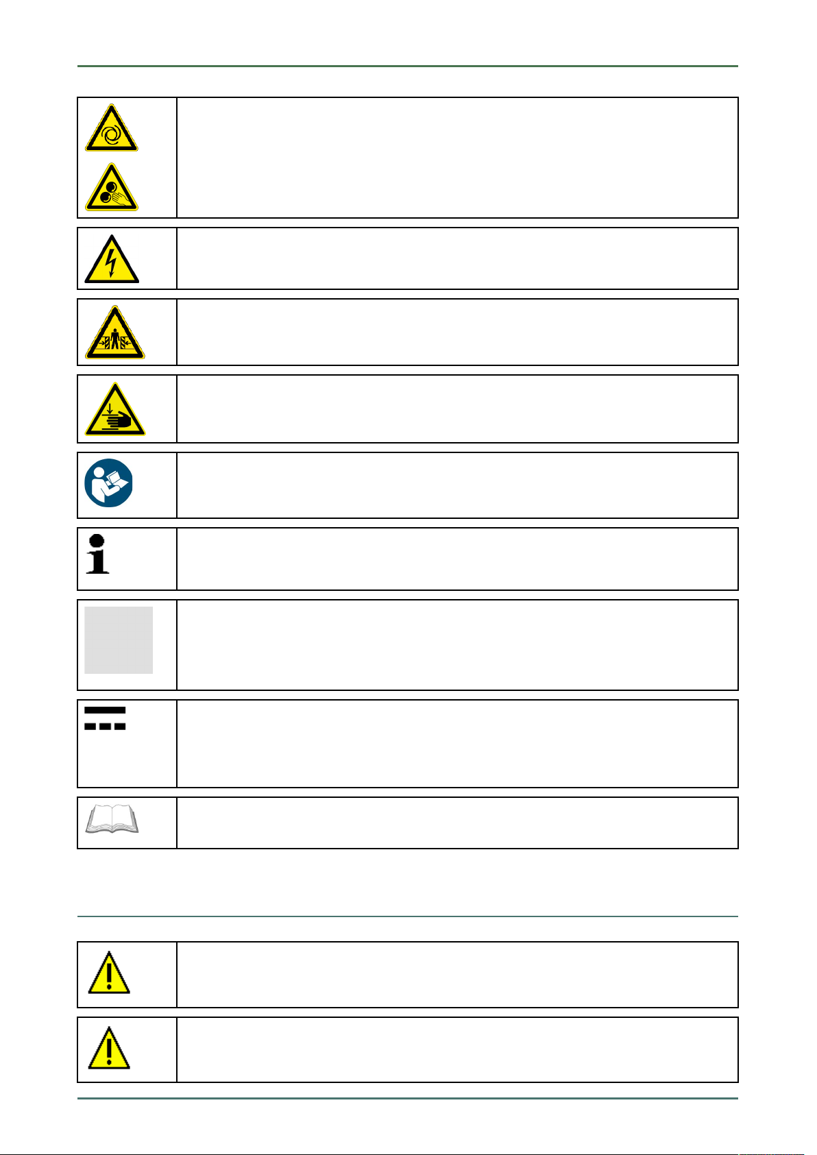
Symbols on the Product
These symbols indicate rotating parts.
This symbol indicates dangerous electric voltage/high voltage.
This symbol indicates the risk of crushing limbs.
This symbol indicates a potential injury of the hand.
NOTICE
All texts labeled NOTICE refer to a hazard in the device or environment. Therefore, it is absolutely
necessary to observe the notes or instructions stored here.
NOTE
Texts marked with NOTE contain important and helpful information. It is recommended to
observe these texts.
Crossed out waste bin
This label indicates that the product must not be discarded as domestic waste.
The bar underneath the waste bin indicates whether the product was "placed on the market" after
August 13, 2005.
Direct current voltage
This label indicates a direct current voltage.
Direct current voltage means that the electrical voltage does not change over a longer period of
time.
Observe user manual
This label indicates that the user manual must always be read and always be available.
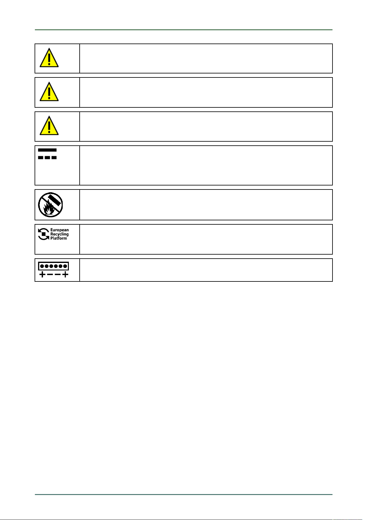
1.3 Symbols on the Product
DANGER
Text parts marked in this way indicate an imminent dangerous situation which, if not avoided, will
lead to death or severe injuries.
WARNING
Text parts marked in this way indicate a potentially dangerous situation which, if not avoided, will
lead to death or severe injuries.
9
About this Manual mega macs 56 Bike
Symbols on the Product
CAUTION
Text parts marked in this way indicate a potentially dangerous situation which, if not avoided, will
lead to minor or slight injuries if it is not avoided.
Observe user manual
This marking indicates that the user manual/the operating instructions must always be read and
always be available.
Observe user manual
This marking indicates that the user manual/the operating instructions must always be read and
always be available.
Direct current voltage
This label indicates a direct current voltage.
Direct current voltage means that the electrical voltage does not change over a longer period of
time.
Fire hazard
This label indicates that the object must not be thrown into open fire.
European Recycling Platform (ERP)
The label indicates the possibility of region-wide return of private electronic devices by post as
packages.
Polarity
This label indicates electric voltage between 2 points.
10
mega macs 56 Bike User Information
Safety Precautions
2 User Information
2.1 Safety Precautions
2.1.1 General Safety Precautions
• The device is intended for use on motor vehicles only. It is a precondition for the use of the
device that the user has knowledge of automotive technology and is therefore aware of the
sources of danger and risks in the workshop and on motor vehicles.
• Please read the entire user manual thoroughly and carefully before using the mega macs 56
Bike. You can also find the user manual under
enclosed.
• All notes given in the individual sections of this user manual apply. The following measures
and safety precautions must also be followed.
• Furthermore, pay attention to all general instructions from labor inspectorates, trade
associations and vehicle manufacturers as well as all laws, legal ordinances and instructions
which have to be commonly obeyed by a repair shop.
in the mega macs 56 Bike or on the DVD
2.1.2 Safety Precautions for the mega macs 56 Bike
To prevent incorrect handling and consequent injuries to the user or damage to the device,
observe the following:
• Select functions and menus on the touch screen display only with clean fingers. Do not use a
tool, e.g. screwdriver.
• Only connect original power adapter to the power cord (supply voltage 12–15 V).
• Protect the TFT LCD and the device from long periods of exposure to solar radiation.
• Protect the device and the connecting cable from hot components.
• Protect the device and the connecting cables from rotating parts.
• Regularly check the connecting cables/accessory parts for damage (destruction of the device
due to short circuit).
• Connect the device exclusively according to user manual.
• Keep the device away from fluids such as water, oil or gasoline. The mega macs 56 Bike is not
waterproof.
• Protect the device from strong impacts and do not drop it.
• Do not open the device on your own. Only technicians authorized by Hella Gutmann are
allowed to open the device. Warranty and guarantee will be rendered void at any case of
unauthorized tampering of the device or if the protective seal is damaged.
• If the device malfunctions, contact Hella Gutmann or a Hella Gutmann trading partner without
delay.
11
User Information mega macs 56 Bike
Safety Precautions
2.1.3 Safety Precautions for High Voltage/Line Voltage
Very high voltages occur in electrical systems. Due to voltage flashover on damaged components,
such as marten damage or touching live components, the risk of electric shock is likely. High
voltage via the vehicle and line voltage via the building's mains supply can cause severe injury or
even death if adequate care is not taken. Therefore regard the following:
• Only use power supply cables with grounding contact.
• Only use a checked or the attached power cord.
• Always use the original cable set.
• Regularly check cables and adapters for damage.
• Always connect the ground cable from device to vehicle first.
• Perform any assembly work such as the connection of the device to the vehicle or the
replacement of components only when ignition is switched off.
• Do not touch live components when ignition is switched on.
2.1.4 Safety Precautions – Risk of Injury
When working on the vehicle, there is a risk of injury through rotating parts or rolling of the
vehicle. Therefore regard the following:
• Prevent the vehicle from rolling.
• Additionally place gear selector lever of AT vehicles to park position.
• Deactivate the start/stop system to avoid an inadvertent engine startup.
• Connect the device to the vehicle only when engine is shut down.
• Do not reach into rotating components when engine is running.
• Do not run cables near rotating parts.
• Check the high-voltage parts for damage.
2.1.5 Safety Precautions – Chemical Burns
If the TFT display is damaged, there is a danger of chemical burns due to the escape of liquid
crystal. Therefore regard the following:
• Immediately rinse affected parts of the body or clothing with water (consult a doctor).
• Seek medical attention immediately after inhaling or swallowing.
2.1.6 Safety Precautions Regarding the Risk of Pinching/Crushing
Pay attention not to pinch or crush any limbs when removing/inserting the modules in the mega
macs 56 Bike. Therefore regard the following:
• Pay attention not to reach into the danger zone when inserting the module into the device.
12

mega macs 56 Bike User Information
Safety Precautions
2.1.7 Safety Precautions for Hybrid/Electric Vehicles
Very high tensions occur on hybrid and electric vehicles. Due to voltage flashover on damaged
components, such as marten damage or touching live components, the risk of electric shock is
likely. High voltage at or in the vehicle can lead to death in case of inattention. Therefore regard
the following:
• Only the following qualified employees are allowed to de-energize the high-voltage system:
– High-voltage technician
– Skilled electrician for predetermined operations – Hybrid or rather electric vehicles
– Skilled electrician
• Place warning signs and warning tapes.
• Check the high-voltage system and the high-voltage lines for damage (visual inspection!).
• De-energizing the high-voltage system:
– Switch off ignition.
– Disconnect the service disconnect plug.
– Remove the fuse.
• Securing the high-voltage system against re-activation:
– Withdraw the ignition key and keep it safe.
– Keep the service disconnect plug safe or secure the battery master switch against re-
activation.
– Insulate the battery master switch, the plug connections etc. with dummy plugs, covering
caps or insulating tape with the corresponding warning notice.
• Check the de-energized state with a voltage tester. Even with disconnected high-voltage
system, residual voltage can still be present.
• Ground and short-circuit the high-voltage system (necessary only if voltage is higher than
1000 V).
• Voltage below 1000 V: Cover the parts which are close to the system or which are energized e.
g. with insulating cloth, hoses or plastic coverings. Voltage higher than 1000 V: Cover the parts
with insulating plates/protective panels specially developed for this purpose so that sufficient
protection against contact to adjacent parts is ensured.
• Regard the following before re-energizing the high-voltage system:
– All tools and utilities are removed from the hybrid/electric vehicle.
– Remove the grounding and short circuit of the high-voltage system. Do not touch any of
the cables now.
– Attach the protective paneling that has been removed before.
– Remove the protective measures at the switching system.
13
User Information mega macs 56 Bike
Non-Liability
2.1.8 Safety Precautions for Testing/Measuring Devices
• Perform measurements only on electric circuits that are not directly connected to the line
voltage.
• Never exceed the maximum permissible voltage load of 30 V alternating voltage (AC) or 60 V
direct current voltage (DC) respectively.
• Do not exceed the voltage limits indicated on the connecting cables.
• The voltage values to be measured must be shielded extra or even twice from dangerous line
voltage. The voltage limits printed on the test leads must not be exceeded. Pay attention that
the allowed measuring range of 60 V/DC / 42 V peak is not exceeded when measuring positive
and negative voltage at the same time.
• Never perform measurements on ignition systems.
• Regularly check the test and measuring devices for damage.
• Always connect the test and measuring devices to the measurement module (MT 56) first.
• Do not touch the connections/measurement points during the measurement.
2.2 Non-Liability
2.2.1 Software
2.2.1.1 Safety-Relevant Software Modifications
The present device software provides numerous diagnostic and configuration functions. Some of these functions affect
the behavior of electronic components. These components also include components in safety-related vehicle systems,
e.g., airbag or brakes. The following notes and instructions also apply to future updates and related software
extensions.
2.2.1.2 Performing Safety-Relevant Software Modifications
• Work on safety-related areas, e.g. the occupant safety system and the brake system, is only allowed to be
performed if the user has read and accepted this note.
• The user of the diagnostic device must comply fully with all work steps and conditions given by the device and the
vehicle manufacturer, and follow the related instructions without fail.
• Diagnostic programs that make safety-related software modifications in the vehicle may and are only allowed to
be used if the related warning notes including the declaration given in the following are accepted without
reservation.
• It is imperative that the diagnostic program is used correctly, as programs, configurations, settings, and indicator
lamps can be deleted/cleared with it. These changes affect and modify safety-related data and electronic controls,
in particular safety systems.
2.2.1.3 Prohibition of Safety-Relevant Software Modifications
Changes or modifications to electronic controls and safety-related systems are not allowed to be made in the
following situations:
• The ECU is damaged and it is not possible to read out the data.
• The ECU and its allocation cannot be read out unambiguously.
• Reading out is not possible due to data loss.
14

mega macs 56 Bike User Information
Non-Liability
• The user does not have the related training and knowledge necessary.
In these cases the user is not allowed to change programs, configurations, or to make other changes in the safety
system. To avoid any danger, the user has to contact an authorized dealer instantly. Only an authorized dealer can
guarantee the safe function of vehicle electronics together with the factory.
2.2.1.4 Waiver of the Use of Safety-Relevant Software Modifications
The user undertakes not to use any safety-related software functions if one of the following conditions arise:
• There are doubts about the specialized skills of third parties to use these functions.
• The user does not have the prescribed training qualifications.
• There are doubts about the correct function of the safety-related software engagement.
• The device is transferred to a third party. Hella Gutmann Solutions GmbH is unaware of this fact and has not
authorized the third party to use the diagnostic program.
2.2.1.5 Offer for All
The Hella Gutmann Solutions GmbH uses open source software components in the mega macs 56 diagnostic device.
The open source software must be made generally available to all if needed. A standard data carrier should be used
for this purpose. The actual costs incurred are invoiced. The offer is valid for 3 years starting from the date the
diagnostic device is purchased or a change is made to the software specified above.
2.2.2 Non-Liability
2.2.2.1 Data and Information
The information in the database of the diagnostic program has been compiled based on automotive and importer
information. Great care was taken to ensure the correctness of the information. The Hella Gutmann Solutions GmbH
accepts no liability for any mistakes and the resulting consequences. This statement also applies to the use of data
and information that are found to be incorrect or that were incorrectly displayed, also to errors that occurred
inadvertently during compilation of the data.
2.2.2.2 Burden of Proof on the User
The burden of proof is on the user of the device, that he has paid attention to technical explanations, notes on
operation, equipment care as well as maintenance and safety without exception.
2.2.3 Data Protection
The Customer agrees that its data may be stored for implementing and executing the contractual relationship and that
technical data may be stored for performing data audits relevant to data security, statistical analysis and quality
control. The technical data shall be stored separately from personal data and shared only with our contractors. We are
obliged to treat all customer data that we receive confidentially. We may only disclose customer data if statutory
provisions permit or require such disclosure or if the Customer has agreed.
2.2.4 Documentation
The notes given in the device describe the most common fault reasons. However, there are often further reasons for
existing faults, which cannot be listed here, or there are further sources of error, which are unknown yet. The Hella
Gutmann Solutions GmbH is not liable for failed or unnecessary repair work.
15

User Information mega macs 56 Bike
Non-Liability
The Hella Gutmann Solutions GmbH does not accept any liability for the usage of data and information that are found
to be incorrect or that were incorrectly displayed, also for errors that occurred inadvertently during the compilation of
the data.
Notwithstanding the above, the Hella Gutmann Solutions GmbH does not accept any liability for any losses in relation
to loss of profit, goodwill, or any other loss, including financial loss.
Hella Gutmann Solutions GmbH accepts no liability for damages or operating trouble resulting from failure to observe
the "mega macs" user manual and the special safety precautions.
The burden of proof is on the user of the device, that he has paid attention to technical explanations, notes on
operation, equipment care as well as maintenance and safety without exception.
16
mega macs 56 Bike
3 Device Description
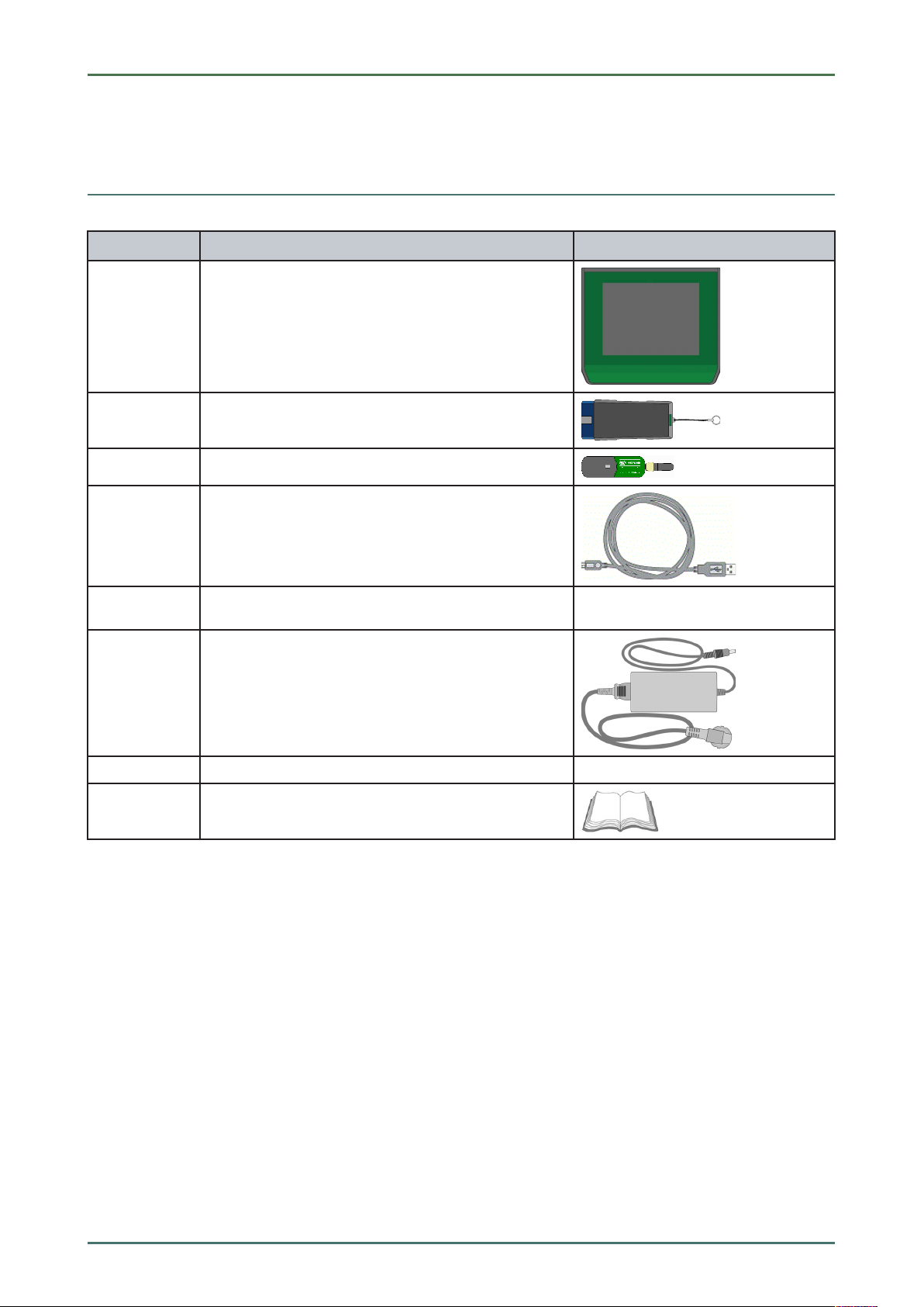
3.1 Delivery Contents
QQuuaannttiittyy DDeessiiggnnaattiioonn
Device Description
Delivery Contents
1
1 DT VCI
1
1
1
1 each Power adapter and power cord for the mega macs 56
mega macs 56 Bike
Bluetooth® adapter
USB cable for connecting the DT VCI to the device
USB cable for connection to a PC
Bike
1
1
HGS data carrier
Quick Start Guide
3.1.1 Checking Delivery Contents
Please check the delivery contents upon receiving your device so that complaints can be issued immediately regarding
any potential damage.
Proceed as follows to check the delivery contents:
1. Open the package supplied and check for completeness based on the delivery slip.
Should you identify any damage to the package, then open the package in the presence of the delivery service and
check the device for hidden damage. Any transport damage to the package supplied and damage to the device
shall be registered in a damage report by the delivery service.
17
Device Description
Intended Use
2. Take the device out of the packaging.
CAUTION
Danger of short circuit due to loose parts in or on the device
Danger of destruction of the device and/or the automotive electronics
Never put the device into operation if you suspect that there are loose parts inside or on the
device. In this case please contact the Hella Gutmann repair service or a Hella Gutmann trading
partner immediately.
3. Check the device for mechanical damage and shake it slightly to ensure that there are no loose parts inside.
mega macs 56 Bike
3.2 Intended Use
The mega macs 56 Bike is a mobile diagnostic device for detecting and rectifying faults in automotive electronic
systems.
It uses a diagnostic interface to establish a connection to the automotive electronics and to provide access to
descriptions of the vehicle system. A lot of this data is transferred to the device directly from the Hella Gutmann
diagnostic database via online connection. Therefore, the device must be permanently online.
The device is not suitable for repairing electrical machines and equipment or home electrics. Diagnostic devices from
other manufacturers will not be supported.
If the device is used in a way not authorized by Hella Gutmann, the safety of the device may be influenced.
3.3 Using the Bluetooth® Function
The terms of use of the Bluetooth® function may be restricted or prohibited through law or corresponding legal
regulations in certain countries.
Observe the provisions in force in the respective country before using the Bluetooth® function.
3.4 Range of Functions
The range of functions of the mega macs 56 Bike depends on the country, the licenses acquired, and/or the optionally
available hardware. This documentation may therefore describe functions that are not available on the individual
device. Missing functions can be enabled by acquiring a corresponding license subject to charge and/or additional
hardware.
3.5 Operating the Device
NOTICE
Damage or destruction of the display
Never touch the display using a tool or pointed metal object.
Always use your finger.
The device is equipped with a touch screen display. All menus and functions can be selected and or activated by
slightly touching with the finger or just by pressing the arrow keys
18
.

mega macs 56 Bike
Connections of the mega macs 56 Bike
3.6 Connections of the mega macs 56 Bike
DDeessiiggnnaattiioonn
Device Description
1
2
3
4
5
6
7 ST3 connector
USB device interface
Use the USB device interface for data exchange between the PC and the device.
2 USB host interfaces
Connect external devices such as a printer or the DT VCI through the USB host interfaces (USB
interfaces for short).
Power supply socket
Voltage supply of the device and battery charge connection.
ON/OFF button
Switch the device on and off.
Measurement module MT 56
The module contains a 2-channel oscilloscope for the following measured variables:
• Voltage
• Current (with amp clamp)
• Resistance
Oscilloscope 1 connectors
Connect a test lead to Scope 1.
• blue = signal
• black = ground
Here you can connect an amp clamp.
8
9
Oscilloscope 2 connectors
Connect a test lead to Scope 2.
• red = signal
• black = ground
Additional module slot
Spare slot. Insert another module here.
Internal: 1x WLAN, 1x Bluetooth® module
All wireless connections are integrated in the device and are permanently switched on.
19
Device Description
DT VCI Connections
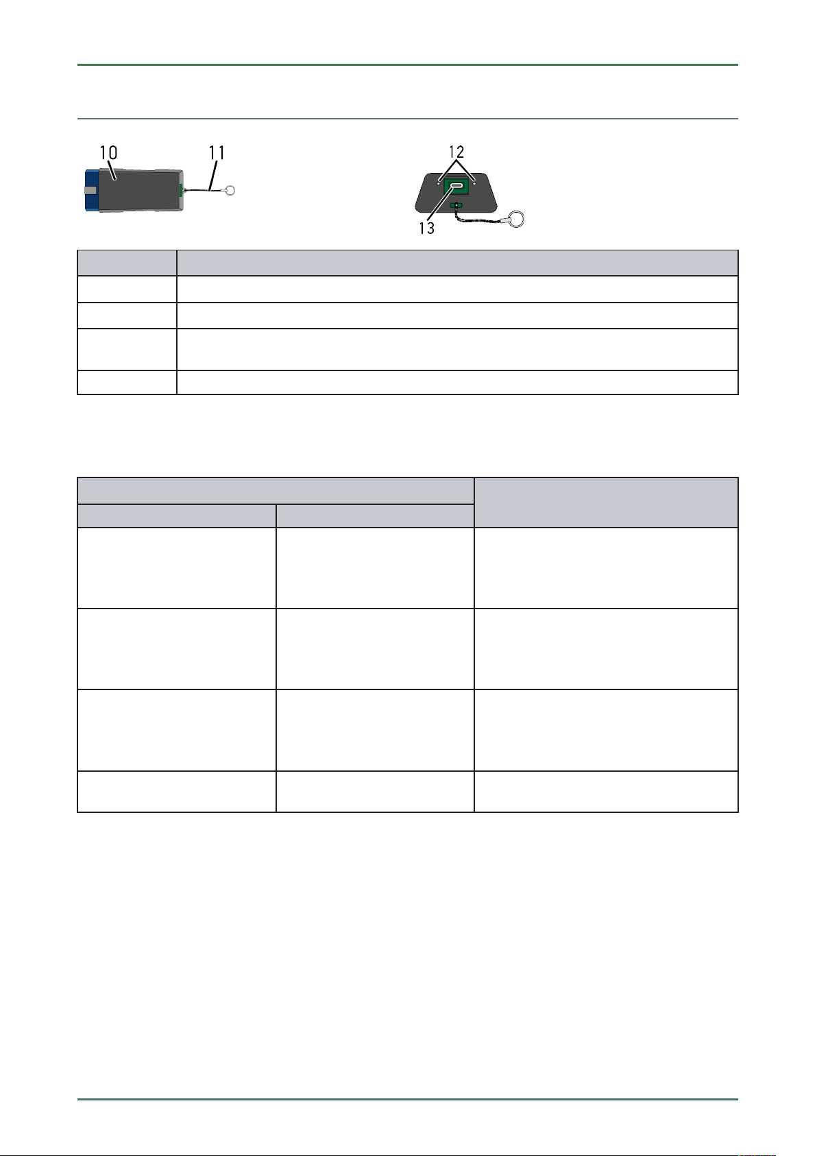
3.7 DT VCI Connections
DDeessiiggnnaattiioonn
mega macs 56 Bike
10
11
12
13
DT VCI for diagnostic connector in the vehicle
Retaining strap for mounting e.g. a lanyard
Green and blue indicator lamp (LED)
The indicator lamps show the operating status of the DT VCI.
Micro USB interface for USB cable to USB interface of the PC
3.7.1 Meaning of the Flashing Frequencies
SSttaattuuss ddiissppllaayy
BBlluuee LLEEDD
LED switched off. LED switched off.
LED flashes quickly (1x per sec.). LED switched off.
GGrreeeenn LLEEDD
• Software inactive/faulty.
• No voltage present.
• DT VCI faulty.
• Update failed.
• Update invalid.
• DT VCI faulty.
MMeeaanniinngg
LED flashes slowly (every 3
sec.).
LED flashes slowly (every 3
sec.).
LED switched off.
LED permanently on with
regular brief interruptions.
• Update failed.
• Update invalid.
• DT VCI faulty.
DT VCI ready for operation.
20

mega macs 56 Bike Installation of the Hella Gutmann Drivers Package
System Requirements of Hella Gutmann Drivers
4 Installation of the Hella Gutmann Drivers Package
4.1 System Requirements of Hella Gutmann Drivers
• Windows 7 SP1 or higher
• Windows administrator rights
4.2 Installation of the Hella Gutmann Drivers Package
To obtain all the data about the related vehicle provided by Hella Gutmann, the device requires a permanent online
connection and the installed driver package Hella Gutmann Drivers. To keep the connection costs down, Hella
Gutmann recommends a DSL connection and a flat rate.
1. Install the Hella Gutmann Drivers on the office or repair shop PC.
The driver package Hella Gutmann Drivers program is on the supplied HGS data carrier.
2. Connect the device to a web-compatible PC.
Once the connection symbol
been set up successfully and is active.
in the top symbol bar changes from black to green, the online connection has
21
Initial Start-Up mega macs 56 Bike
Charging the Battery
5 Initial Start-Up
This section gives a description of how to switch the device on and off as well as all the necessary steps for the first
use of the device.
5.1 Charging the Battery
Prior to putting the device into operation, charge the battery for at least 8 to 10 h while the device is switched off.
Proceed as follows to charge the battery:
1. Insert the voltage supply plug into the device's socket.
2. Insert the power plug into the plug socket.
The battery is being charged.
5.2 Switching on the Device
NOTE
When starting the device for the first time and after every software update, you need to confirm
the general terms and conditions (GTC) of the Hella Gutmann Solutions GmbH. Otherwise, certain
device functions will be unavailable.
If mega macs 56 Bike recovery ("Rescue App") is displayed when switching on the device, please
contact the responsible support staff or the Hella Gutmann Technical Help Line.
Proceed as follows to switch on the device:
1. Briefly push the ON/OFF button.
The GTCs appear.
2. Read the GTCs and confirm them at the end of the text.
The user selection window is displayed. The respective user name is saved for all data stored in the Car History.
This enables quicker identification of the mechanic who performed the repair work if a query is subsequently
made.
3. Double-click
4. Enter the user name.
5. Confirm your entry with
6. Activate the Stay logged in check box if necessary.
If the Stay logged in check box is activated, you will not need to select a user name when switching on in the
future.
7. Confirm your entry with
The input will be saved automatically. The main menu appears.
.
.
.
Now you can start working with the device.
5.3 License Release
NOTE
In order to use the full scope of the purchased licenses you need to connect the device to the HGS
server prior to the first start-up.
Proceed as follows to connect the device with the HGS server:
22
mega macs 56 Bike Initial Start-Up
Switching off the Device
1. Select Contracts under > Settings in the main menu.
2. Select >License<.
3. Call up My licenses with
Data download is in progress. Purchased licenses are displayed.
4. Switch the device off and on again.
Now you can start working with the device.
.
5.4 Switching off the Device
Proceed as follows to switch off the device:
NOTE
Under normal conditions it is sufficient to switch off the device with
the device must be switched off with the ON/OFF button so that it cannot be switched on
unintentionally.
1. Switch off the device with
2. Observe the confirmation prompt.
3. Switch off the device with
After switching off, the device is in standby mode.
.
. Abort the procedure with .
. For transport and storage
23

Configuring the Device mega macs 56 Bike
Setting company data
6 Configuring the Device
Configure all interfaces and functions under Settings in the main menu.
6.1 Setting company data
Here you can enter the company data, that shall appear on the hard-copy printout, e.g.:
• Company address
• Fax number
• Homepage
6.1.1 Entering Company Data
Proceed as follows to enter the company data:
1. Select Company under > Settings in the main menu.
2. Select >Company data<.
3. Open the virtual keypad under Company name with
4. Enter the company name.
5. Confirm your entry with
The input will be saved automatically.
6. Repeat steps 3-5 for further entries.
.
.
6.1.2 User Name
6.1.2.1 Entering the User Name
Here you can manage the different users.
The respective user name is saved for all data stored in the Car History. This enables quicker identification of the
mechanic who performed the repair work if a query is subsequently made.
Proceed as follows to enter the user name:
1. Select Company under > Settings in the main menu.
2. Select >User<.
3. Open the virtual keypad with
4. Enter the user name.
5. Confirm your entry with
The input will be saved automatically.
.
.
6.1.2.2 Assigning a Password
Here you have the option to assign passwords to the users.
The assigned password must be entered when selecting the user.
Proceed as follows to assign a password to a user:
1. Select Company under > Settings in the main menu.
24

mega macs 56 Bike Configuring the Device
Setting company data
2. Select >User<.
3. Select the required user name.
4. Open the virtual keypad with
5. Enter the requested password.
6. Confirm your entry with
The input will be saved automatically.
.
.
6.1.2.3 Deleting the Password
Proceed as follows to delete the password:
1. Select Company under > Settings in the main menu.
2. Select >User<.
3. Selected the requested user name with the assigned password.
4. Delete the password under Password (optional) with
5. Observe the confirmation prompt.
6. Confirm the confirmation prompt with
Password will be deleted.
.
.
6.1.2.4 Deleting the User Name
Proceed as follows to delete the user name:
1. Select Company under > Settings in the main menu.
2. Select >User<.
3. Select the required user name.
4. Delete the user name with
5. Observe the confirmation prompt.
6. Confirm the confirmation prompt with
The user name is deleted.
.
.
6.1.2.5 Activating the Car History
Proceed as follows to activate the Car History:
NOTE
Only if the check box Car History active is activated the data records will be saved automatically
in the Car History.
1. Select Company under > Settings in the main menu.
2. Select >User<.
3. Activate the check box Car History active.
Now data records will be saved in the Car History.
25
Configuring the Device mega macs 56 Bike
Updating the Device, DT VCI and Modules
6.1.2.6 Setting Up Password Protection
Introduction of the General Data Protection Regulation (GDPR) of the European Union on 25 May 2018 includes the
requirement to ensure better protection for customer-related data in devices and equipment.
To prevent access to our diagnostic devices by third parties, we have integrated the function Password protection.
NOTE
Due to legal requirements concerning third party access, the device can only be reactivated via the
function >Starting the factory reset< or the Technical Hotline of Hella-Gutmann Solutions. In
this case the personal data and the Car History will be cleared and might possibly not be restored.
Proceed as follows to set up the password protection:
1. Select Company under > Settings in the main menu.
2. Select >User<.
3. Call up Password management with
NOTE
The length of the password must not exceed 10 characters.
4. Enter a password and confirm by entering it again.
5. Observe the warning notice and confirm.
The device can now be accessed only with the selected password.
.
6.2 Updating the Device, DT VCI and Modules
Here you can perform the updates for the device, the DT VCI and the individual modules. Various system parameters
are also displayed, e.g.:
• Package version
• Device number
• Software version
Hella Gutmann Solutions supplies customers with regular software updates. The update is subject to charge. These
updates contain new vehicle systems as well as technical modifications and improvements. We recommend keeping
your device up to date.
26

mega macs 56 Bike Configuring the Device
Updating the Device, DT VCI and Modules
6.2.1 Preconditions for an Update
Ensure the following to perform updates:
• Device is connected to a web-compatible PC through USB cable, Bluetooth® or WLAN.
• A Bluetooth®-compatible PC or Bluetooth® adapter is plugged into the PC.
• The corresponding licenses are activated by Hella Gutmann.
• The driver package Hella Gutmann Drivers is installed on the PC.
• Voltage supply of device and DT VCI is ensured.
6.2.2 Calling Up System Information
Here you can find all information required for the identification of the mega macs 56 Bike.
Proceed as follows to call up system information:
1. Select Update under > Settings in the main menu.
2. Select >System<.
An info window appears.
Here you can find information including the software and hardware version and the device number.
6.2.3 Setting the Language
Here you can set the language version if the software is multilingual. After having set the language, the update will be
installed in this language.
Proceed as follows to set the language:
1. Select Update under > Settings in the main menu.
2. Select >System<.
3. Open the list under Language setting with
The compilation of languages depends on the prevailing software.
4. Select the requested language.
The selection will be saved automatically.
.
6.2.4 Starting the System Update
Here you can start a system update.
Proceed as follows to start the system update:
1. Select Update under > Settings in the main menu.
2. Select >System<.
NOTICE
Insufficient voltage supply
System data loss
Do not switch off the device and the DT VCI during the update and do not disconnect them from
voltage supply.
Ensure sufficient voltage supply.
27
Configuring the Device mega macs 56 Bike
Updating the Device, DT VCI and Modules
3. Start Update under Step with .
The device searches for a new update that will then be downloaded and installed.
The device switches off and on again after the successful system update. The installation will be checked automatically
after startup.
6.2.5 Calling Up DT VCI Information
Here you will find all information required for the identification of the DT VCI.
Proceed as follows to call up DT VCI information:
1. Select Update under > Settings in the main menu.
2. Select >DT VCI<.
An info window appears.
This menu provides the software and hardware version and the module type of the DT VCI.
6.2.6 DT VCI Update
Update the software for the DT VCI here.
6.2.6.1 Starting a DT VCI Update
NOTICE
Insufficient voltage supply
System data loss
Do not switch off the device and the DT VCI during the update and do not disconnect them from
voltage supply.
Ensure sufficient voltage supply.
Proceed as follows to start the DT VCI update:
1. Select Update under > Settings in the main menu.
2. Select >DT VCI<.
CAUTION
Rolling of vehicle
Risk of injury or material damage
Proceed as follows before starting:
1. Prevent the vehicle from rolling.
2. No gear is engaged.
3. Regard the window with infos and instructions.
NOTICE
Short circuit and voltage peaks when connecting the DT VCI
Danger of destruction of automotive electronics
Switch off ignition before connecting the DT VCI to the vehicle.
3. Insert the DT VCI into the vehicle's diagnostic connector.
Both LEDs of the DT VCI flash. The DT VCI is ready for operation.
28
mega macs 56 Bike Configuring the Device
Configuring the Interfaces
4. Start Update with .
5. Regard the window with infos and instructions.
6. Confirm the window with infos and instructions with
The DT VCI update will be started. Data is copied from device to DT VCI.
The message Update (DT VCI/MT 56) successful appears if the update was successful.
.
6.2.7 Module Update
Update the software for individual modules here.
The mega macs 56 Bike has 2 module slots. The 1st module slot is intended for the MT 56 (measurements module)
and the 2nd is a secondary slot for further modules.
6.2.7.1 Starting the Module Update
NOTICE
Insufficient voltage supply
System data loss
Do not switch off the device during the update and do not disconnect it from voltage supply.
Ensure sufficient voltage supply.
Proceed as follows to start the module update:
1. Select Update under > Settings in the main menu.
2. Select the tab for the required module.
An info window appears.
Here you can find information on the software and hardware version and the module type.
3. Start the module update with
4. Regard the window with infos and instructions.
5. Confirm the window with infos and instructions with
The module update will be started. The device searches for a new update that will then be downloaded and
installed.
The message Module update successfully done appears if the update was successful.
.
.
6.3 Configuring the Interfaces
Here you can configure the interfaces for the printer, Bluetooth® and WLAN.
Configure all interfaces of the device under Settings > Interfaces.
If there are several possible connections to devices or tools, the fastest and most stable connection is always
preferred.
The hierarchy for connection is as follows:
1. USB
2. Bluetooth®
3. WLAN
29

Configuring the Device mega macs 56 Bike
Configuring the Interfaces
6.3.1 Configuring the Printer
6.3.1.1 Printing via USB Port
Here you can set the option to print via a USB port.
It is possible to connect to the USB ports any printer that supports at least the printer language PCL5 or higher and
that has a USB port. In order to ensure trouble-free support through the Technical Help Line, we recommend using a
printer of Hella Gutmann.
Proceed as follows to print out results via USB port:
1. Plug in the USB cable (not included in the contents of delivery) to the device's and the printer's USB port.
2. Select Interfaces under > Settings in the main menu.
3. Select >Printer<.
4. Open a list under Interface with
5. Select >local<.
6. Open the list under Color mode with
7. Select either >Colour< or >Black/white<.
8. Use
The margins are set ex works to 15 mm.
9. Delete the number set ex works with
10. Enter the requested height of the margins in mm.
11. Confirm your entry with
The input will be saved automatically.
12. Repeat steps 8-11 for further entries.
13. Where necessary, activate the check box Blank out company logo to print out results without the company logo
of Hella Gutmann.
This function enables hard-copy printouts on printed paper.
It is now possible to print using the printer on the USB port.
to open the virtual keypad under top (mm).
.
.
.
or where necessary.
6.3.1.2 Printing with Standard PC Printer
Here you can set the print function with the standard printer connected to the PC.
If there is no additional printer connected to the device, it is possible to print with the printer of a PC system. This
requires a connection between the diagnostic device and the PC. The connection to the PC can be realized with USB
port, Ethernet, Bluetooth®, WLAN or UMTS.
Proceed as follows to print out results with the standard printer:
1. Select Interfaces under > Settings in the main menu.
2. Select >Printer<.
3. Open a list under Interface with
4. Select >Gutmann Portal<.
The selection will be saved automatically.
5. Use
The margins are set ex works to 15 mm.
6. Delete the number set ex works with
7. Enter the requested height of the margins in mm.
30
to open the virtual keypad under top (mm).
.
or where necessary.
 Loading...