

Page 1
de Montageanleitung
fr Instructions de montage
it Istruzioni per il montaggio
en Installation instructions
es Instrucciones de montaje
nl Montagehandleiding
Page 2

en
Safety information
Installation, connection, commissioning
and repair work may only be carried out
by authorised technicians. This technician will be able to determine suitable
methods for securing the extractor hood
and providing the necessary exhaust air
ducting. The choice of attachment must
take account of the weight of the extractor hood and the load exerted on the
supporting surface. Note the extraction
values of the dowels supplied. Depending on the supporting surface, these
have the following values: Dowel Ø10
mm: concrete B25 9.4 kN brick Z20 5.2
KN solid calcium silicate KSV20 4.8 KN.
In the case of unstable supporting surfaces, a construction specialist such as
a structural engineer or architect must
be consulted to ensure the extractor
hood is safely installed.
Danger of injury!
The hood body may contain sharp
edges resulting from the manufacturing
process. For this reason, safety gloves
must be worn when installing it.
Danger of electric shock
The mains voltage must correspond to
the details indicated on the type plate.
This plate is located inside the hood
near the filters. Only connect the extractor hood to a properly installed safety
socket. This socket must be easily accessible after the installation so that the
extractor hood can be disconnected
from the power supply if necessary. If a
fixed connection is used (e.g. if a suitable wall socket is not available), the
extractor hood may only be connected
by a qualified electrician. For fixed connections, the extractor hood must be
connected to a single power circuit fitted
with an isolating device. Isolating devices include switches with a contact
gap of at least 3 mm and all-pole
22
switches, e.g. circuit breakers and contactors. Before working on the electrical
connection of the extractor hood commences, the mains circuit/circuits must
be switched off. Before drilling the
mounting holes, make sure that no electrical cables can be damaged during
drilling. The electrical connection must
be prepared in such a way as to allow
the easy connection of the extractor
hood. Local regulations must be observed.
Exhaust air ducting (for extraction mode)
Exhaust kitchen air must not be ducted
into a chimney flue that is also used for
the exhaust air from devices using fuels
(e.g. gas). Official regulations regarding
ducting of exhaust air must be observed. The exhaust air path must be
prepared in such as way as to allow the
easy connection of the extractor hood.
The exhaust air hose must not have any
kinks. If the extractor hood is operated
in extraction mode at the same time as
other room-air-dependent fire appliances (e.g. wood, gas, oil or coal-fired
appliances) in the same room, lethal
combustion gases may be directed back
into the room due to the resulting negative pressure. The operator must therefore provide a sufficient air supply at all
times. The negative pressure in the
room must not exceed 4 Pa (0.04mbar).
Solid fuel appliances
The installation of the extractor hood
above solid fuel appliances, which can
pose a fire hazard, (e.g. flying sparks) is
only permissible if the solid fuel appliance is equipped with a sealed, nonremovable cover.
Minimum clearance to cooker
The regulation for gas cookers is 650
mm. To prevent the formation of condensation, a non-return valve must be
fitted directly outside the air outlet. Note
Page 3
the relevant applicable installation regulations and installation instructions provided by the manufacturer of the gas
appliance. The extractor hood may only
be installed at a minimum height of 650
mm above gas cookers if the following
nominal heat loads (Hs) are not exceeded:
Gas stoves
Load from one gas ring max. 3.0 KW
Load from all gas rings max. 8.3 KW
Load from oven max. 3.9 KW
Gas hobs
Load from one gas ring max. 3.9 KW
Load from all gas rings max.11.3 KW
We reserve the right to make technical
changes.
Installation instructions
for recirculation C-
en
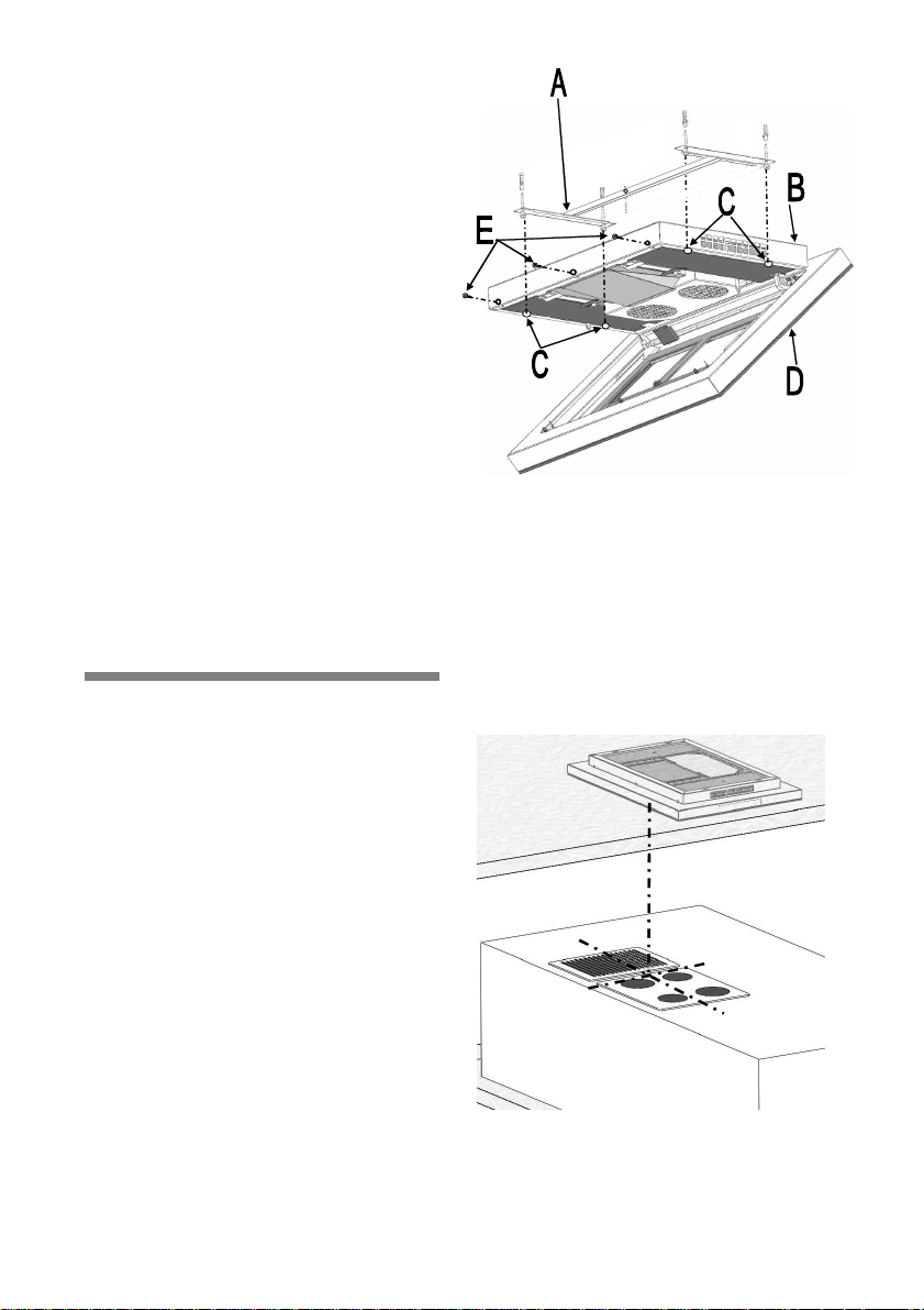
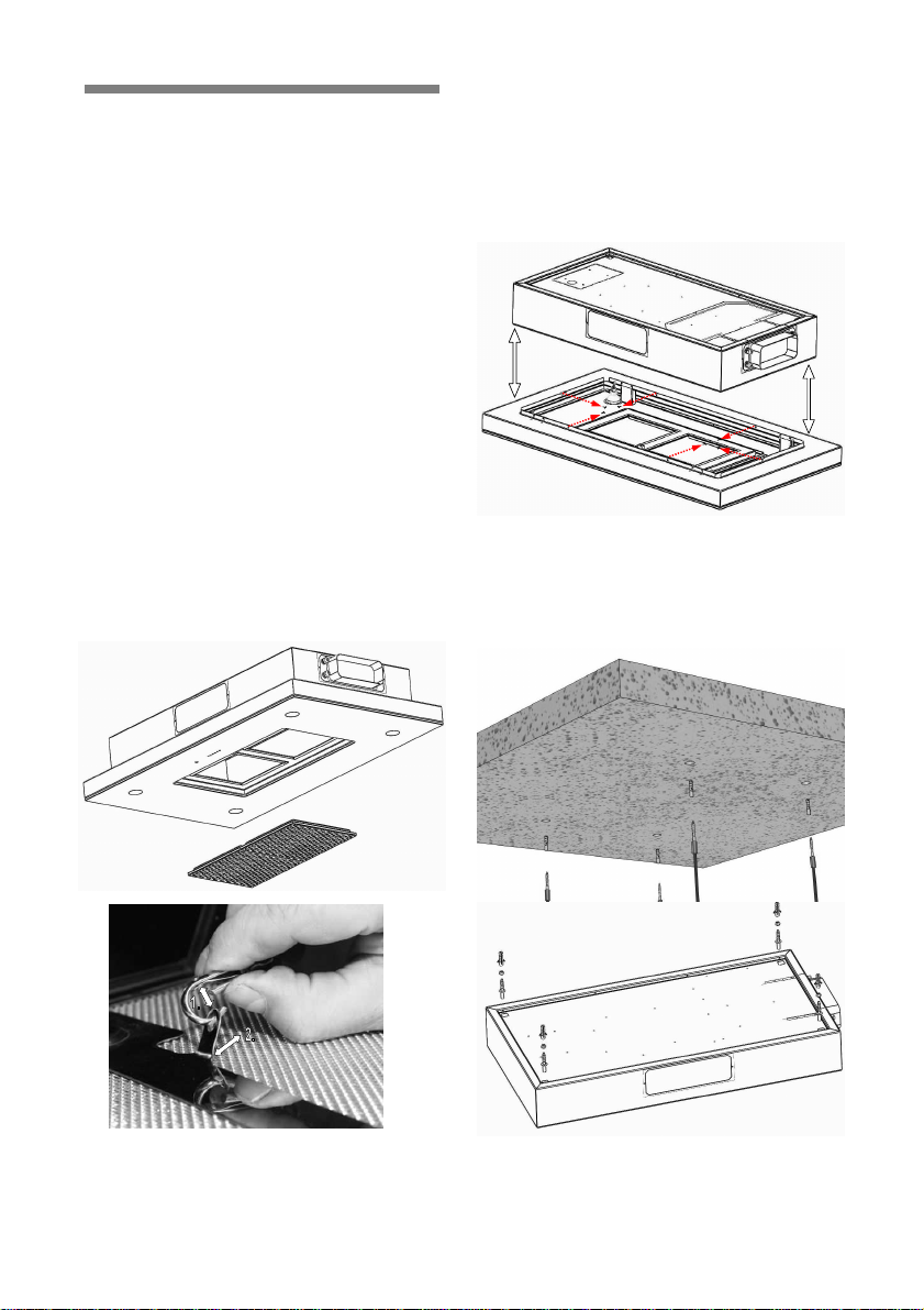
1. The extractor hood must be carefully
removed from the packaging by 2 people and placed on the mounting lift.
Then prepare the installation location on
the ceiling. To achieve optimum extraction capacity, the hood must be positioned in the middle above the cooking
hob. Use a plumb line to mark the centre of the hood on the ceiling.
Version
General:
Before the extractor hood leaves the
works it undergoes an extensive functional test.
To provide a better technical understanding of the interrelationship of functional components, the extractor hood is
delivered pre-assembled in its final condition. However, it must be partially dismantled prior to installation according to
the following instructions.
A = Mounting frame
B = Hood upper section
C = Installation holes
D = Hood lower section
E = Securing bolts
2. Take the installation frame (A) to
transfer the fastening holes for the extractor hood (2 and C) and for the
mounting frame (1 and A) onto the ceiling.
23
Page 4
en
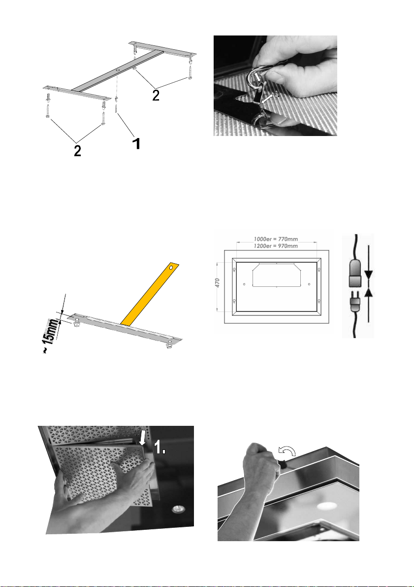
3. Drill the suspension holes in the ceiling and use suitable dowels for the wall
material.
4. Align the mounting frame (1 and A)
screw it tightly onto the ceiling.
Now screw in the bolts for mounting the
hood (2 and C) until they protrude
~15mm from the ceiling.
Then release the locking hook on the
metal filters.
6. Then raise the extractor hood using
the lifting device (make sure it is facing
the correct way) to a distance of approx.
30 cm from the ceiling. At this point,
connect the hood to the power supply.
Pay attention to the area on the ceiling
in which the electrical supply line can be
5. Before using a lift to hang the extractor hood, you must remove the metal
filters.
To do this, use both hands to pull down
the metal filters until the magnet contact
24
routed!
7. Now unscrew the securing bolts (E)
on the hood upper section (B) while
holding the hood lower section (D) with
one hand.
Page 5
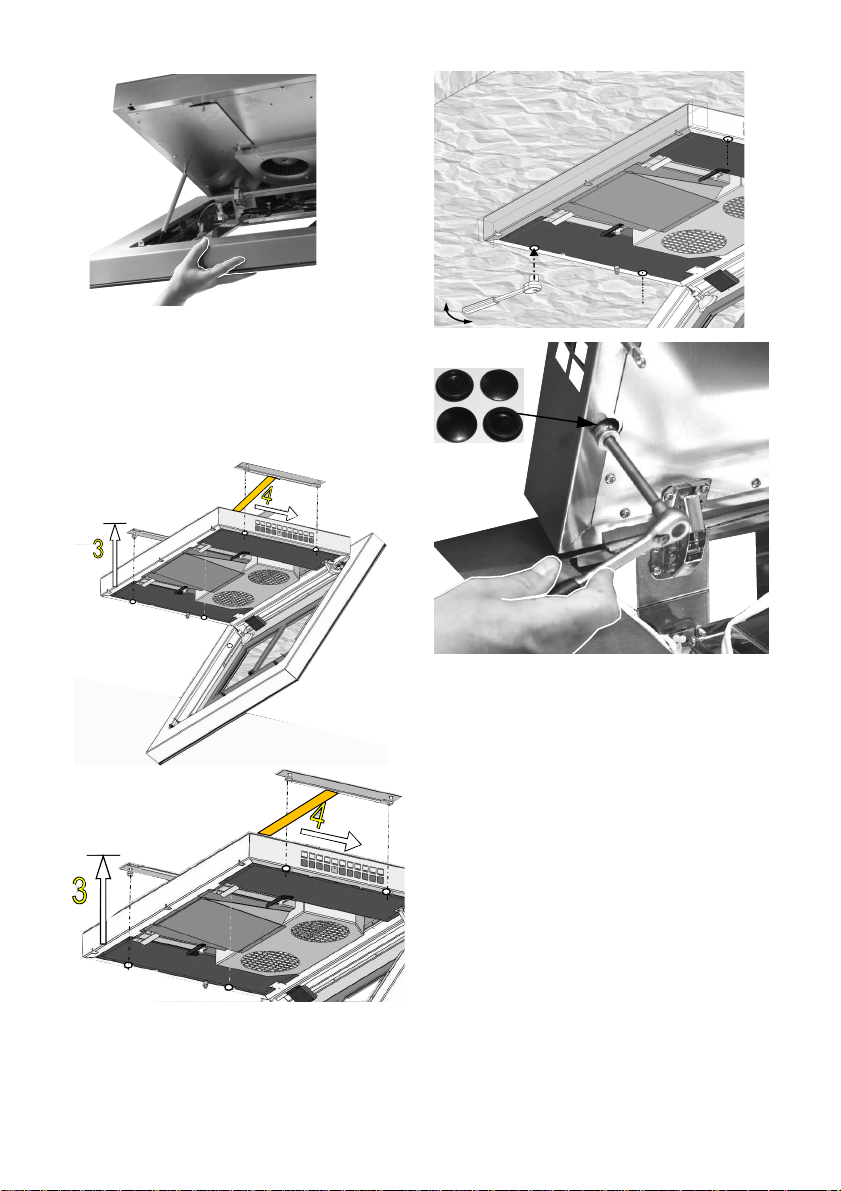
8. Lift up the extractor hood with 2 men
(3) Make sure that the fastening screws
are fitted into the "pear-shaped holes"
on the top of the extractor hood (3).
Then push the extractor hood backwards (4) to lock it in position.
en
9. Then tighten the extractor hood
through the mounting hole using a
ratchet and extension arm.
10. Now fold up the hood lower part (D)
again and screw it on using the securing
bolts (E).
11. Replace the metal filters in the filter
mount (fasten the locking hook).
12. Carry out a function test.
25
Page 6
en
Installation instructions
(
B Version)
General: Before the extractor hood
leaves the works it undergoes an extensive functional test. To provide a better
technical understanding of the interrelationship of functional components, the
extractor hood is delivered preassembled in its final condition. However, it must be partially dismantled prior
to installation according to the following
instructions.
1. Before using a lift to hang the extractor hood, you must remove the metal
filters.
To do this, use both hands to pull down
the metal filters until the magnet contact
releases.
Then release the locking hook on the
metal filters.
2. Now unscrew the screws located in
the exhaust air chamber (M5, Torx) so
that the extractor hood can be separated into its upper and lower sections.
Make sure that the electric lines are
released at the connector plugs.
3. Now transfer the suspension holes on
the hood upper part onto the ceiling
(dimensions vary depending on the
model size), drill the holes, fit the correct
dowels and tighten the hanger bolts.
26
Page 7
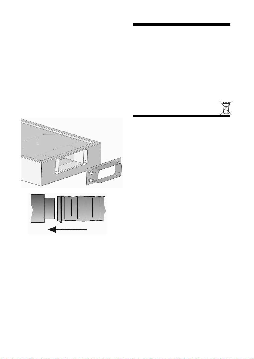
4. Before hanging the upper part of the
Capa hood, check that the exhaust air
connection is facing to the correct side!
Now push the suspension holes in the
upper section onto the hanger bolts in
the ceiling. Tighten the bolts with the
large washers and nuts supplied.
5. Now create the exhaust air connec-
tion between the exhaust air duct/hose
and connecting piece. In the case of
existing false ceilings, the connecting
piece may be removed.
6. Now introduce the supply line via the
cable passages on the upper part.
7. Screw the hood lower part to the
hood upper part (as described under
point 2. but in reverse sequence). Complete the electrical connection.
en
Disposal Packaging
The appliance packaging is recyclable.
Cardboard and polyethylene film (PE)
are used as packaging material. These
materials must be disposed of in an
environmentally friendly manner and in
accordance with the currently valid onsite regulations.
Environmental Information
This appliance is labelled in accordance
with European Directive 2002/96/EG
conceming used electrical and electronic appliances (waste electrical and
eleclronic equipment - WEEE). The
guideline determines the framework for
the return and recycling of used appliances as applicable throughout the EU.
Please ask your dealer about current
means of disposal.
8. Now conduct a function test.
27
Page 8
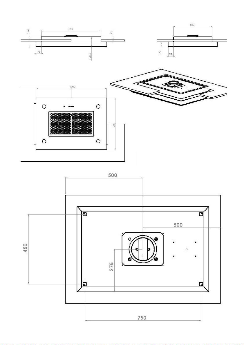
Bild: Capa 1000x700x140mm A-Version
41
Page 9
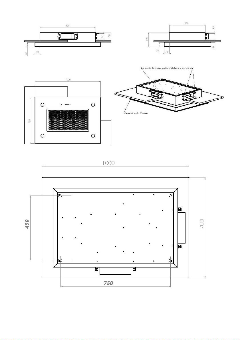
Capa 1000x700x140mm, B-Version
42
Page 10
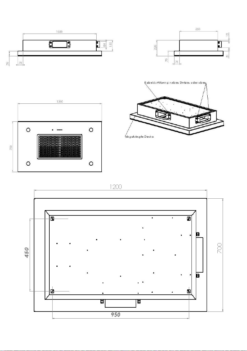
Capa 1200x700x140mm, B-Version
43
Page 11

44
Exklusiv-Hauben GUTMAN
Mühlacker Straße 77
D-75417 Mühlacker
Deutschland
[email protected]
www.gutmann-exklusiv.eu
GUTMAN GmbH
GUTMAN GUTMAN
HRB 705602 Amtsgericht Mannheim
DE263391836
Artikel Nr.: 1803
 Loading...