

Operating instructions
- Translation of the original -
English
GBR
18.4.17
Guth Ventiltechnik GmbH
Horstring 16
D - 76829 Landau
+49 (0) 6341 5105-0Fax: +49 (0) 6341 5105-85
www.guth-vt.de
sales@guth-vt.de
1
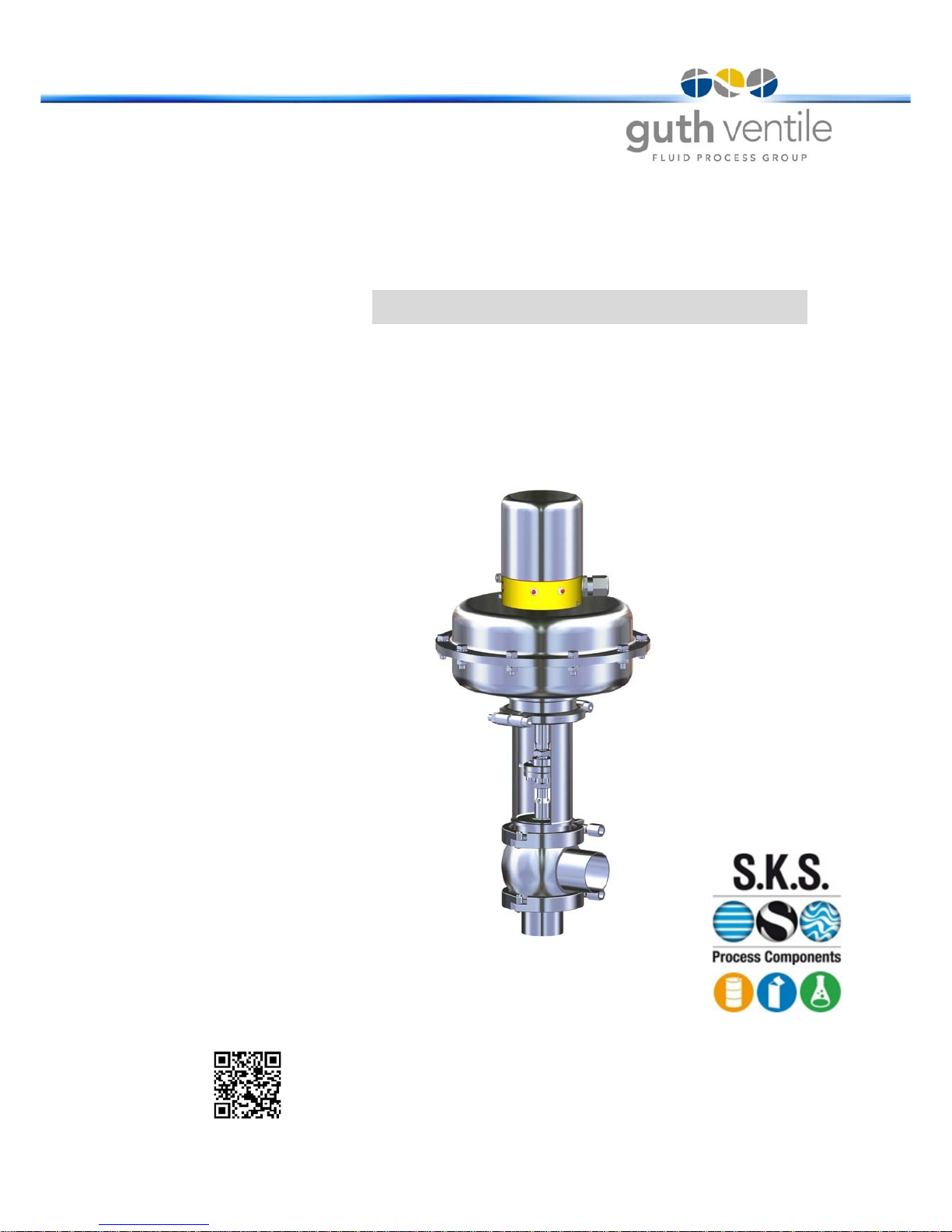
Modulating Valves
Type: VSR
www.sks-online.com
www.sks-webshop.com

18.4.17
Modulating Valves Type: VSR
List of contents
2
Availability and Completeness
These operating instructions constitute part of the valve delivery and must be kept available so that they can be referred to by authorised personnel at any time. No sections may be removed from these instructions. Should the operating instructions or individual pages be missing,
they must be replaced at once.
Change Service
This documentation is subject to the Change Service of Guth Ventiltechnik GmbH.
Changes may be made to this documentation without notice of such changes
being given.
Copyright
This documentation contains information that is protected by copyright. It may only
be used in connection with the use of the valve.
Guth Ventiltechnik GmbH
Horstring 16
D - 76829 Landau
+49 (0) 6341 5105-0Fax: +49 (0) 6341 5105-85
www.guth-vt.de
sales@guth-vt.de
List of contents .......................................................................................................................2
1. General informations ............................................................................................................... 3
1.1 Intended use ................................................................................................................3
1.2 Notes on the guarantee ...............................................................................................3
1.3 Safety instructions........................................................................................................3
1.4 Danger symbols ...........................................................................................................4
2. Technical Data ........................................................................................................................ 5
2.1 General description ......................................................................................................5
2.2 Design of the valve ......................................................................................................5
2.3 Variants........................................................................................................................6
2.4 Housing variants ..........................................................................................................6
2.5 Lantern variants ........................................................................................................... 6
2.6 Actuator variants ..........................................................................................................6
2.7 Controller variants........................................................................................................ 6
2.8 Valve variants ..............................................................................................................7
3. Functional description .............................................................................................................9
4. Installation of the Modulating valve ....................................................................................... 10
4.1 Installation space .......................................................................................................10
4.2 Installation of the fitting ..............................................................................................10
4.3 Pipe connections........................................................................................................ 10
4.4 Welding seam preparation .........................................................................................11
4.5 Pneumtatic connection............................................................................................... 11
4.6 Electrical connection .................................................................................................. 11
5. Commisioning........................................................................................................................ 12
6. Changes to the Modulating valve .......................................................................................... 12
6.1 Changing the Kvs Value and the Flow Rate Curve....................................................12
6.2 Changing the Effective Direction of the Diaphragm Actuator.....................................13
7. Maintenance and repairs.......................................................................................................14
7.1 Inspection...................................................................................................................14
7.2 Replacing the Cone-Seat Assembly ..........................................................................14
7.3 Replacing the Seals ................................................................................................... 15
7.4 Setting the Spindle, Coupling and Diaphragm Actuator............................................. 17
7.5 Lubrication and Maintenance Schedule ..................................................................... 18
7.6 Valve designation.......................................................................................................18
7.7 Cleaning and care......................................................................................................19
8. Malfunctions .........................................................................................................................20
8.1 Mechanical valve defects (Mechanic) ........................................................................ 20
8.2 Defects on the actuator..............................................................................................21
9. Transport, Packaging and Disposal ......................................................................................23
9.1 Transport and Packaging...........................................................................................23
9.2 Disposal .....................................................................................................................23
10. Data sheet for GUTH Modulating valves............................................................................... 24
10.1 Spring-to-close, Valve model series Type L............................................................... 24
10.2 Air-to-close (Air pressure 6bar) Valve Model Series Type L......................................25
11. Technical Information ............................................................................................................26
11.1 Fields of application and materials.............................................................................26
11.2 Tightening torques .....................................................................................................26
12. Konformitätserklärung / Declaration of Conformity / Deklaracja zgodno?ci ......................... 27
List of contents
www.sks-online.com
www.sks-webshop.com

18.4.17
Modulating Valves Type: VSR
1. General informations
3
1. General informations
1 . 1 Intended use
The valve may only be used for areas of use authorized by GUTH. The valve is designed for dosing,
mixing, distributing or reducing in connection with approved media, pressures and temperatures. It
is for use in the foodstuffs, beverages, pharmaceutical and chemical industries.
It has been developed and manufactured in accordance with currently applicable safety standards.
Therefore there is no hazard risk under normal conditions if it is used according to instructions.
1 . 2 Notes on the guarantee
All obligations arising in connection with guarantees are contained in the General Terms and Conditions of Guth Ventiltechnik GmbH.
1 . 3 Safety instructions
The mixer may only be fitted and commissioned by qualified personnel.
Based on the definition laid down in EN 60204-1. Qualified personnel:
A person who, on the basis of his or her specialist training, has acquired knowledge and experience
as well as knowledge of the relevant standards and can evaluate the work entrusted to him or her
and any possible hazards.
NOTICE
Please read this handbook carefully before you begin with the assembly of, commissioning of or
any other work connected with this modulating valve.
• The valve may only be used for approved purposes.
• The company shall accept no liability for damage and operational malfunctions resulting from
failure to observe these instructions.
• Technical modifications resulting in deviations from the illustrations and information contained
in these instructions may be made without prior notice being given.
• The pneumatic actuators contain strongly pre-tensioned springs. This means that there is a
risk of death if actuators are opened. Therefore the actuators may only be opened by qualified
personnel that has been trained by the Guth company.
• Pneumatic actuators exert large positioning forces. Therefore moving parts may only be
touched when not under tension or pressure.
• The device may only be fitted and commissioned in accordance with these operating instructions.
• The manufacturing process did not take account of safety precautions in respect of external
fire.
• Conversion or modification of the fitting may only be carried out in agreement with the Guth
Company.
• The original replacement parts supplied by the Guth Company serve the purpose of ensuring
safety. Should other parts be used, the Guth Company shall accept no responsibility whatsoever for any damage that may result.
• The fitting is designed for connection to protective low voltage only.
• The fitting may only be disassembled when not connected to a voltage supply or under pressure.
• Prior to repair and maintenance operations the product line must be de-pressurised and free
of the product. Product residues and cleaning agents must be removed as well.
• Fittings that come into contact with hazardous media must be decontaminated.
• Never touch the fitting or piping when hot liquids are being processed or the sterilization process is running.
www.sks-online.com
www.sks-webshop.com
18.4.17
Modulating Valves Type: VSR
1. General informations
4
The valve may only be operated when it is in perfect working order. In addition to the documentation, instructions on the following also apply:
- Internal plant working and safety instructions
- National regulations in the country of implementation
- Generally accepted safety regulations
- Accident prevention regulations
Failure to observe the specified hazard warnings may pose a risk to persons as well as the environment, fitting and plant. Specifically, failure to observe the warnings may cause the following hazards to arise:
- the failure of important functions of the fitting and plant
- the failure of prescribed methods for maintenance and repairs
- hazards to persons caused by electrical, mechanical or chemical agents
- environmental hazards on account of leakage of hazardous substances
1 . 4 Danger symbols
Safety instructions and warnings serve to avoid danger to the lives and health of users or maintenance personnel and damage to property. Attention is drawn to them by means of the symbols
defined here. The hazards are also highlighted where they may arise by means of danger symbols
(pictograms). The meaning of the pictograms is as follows:
• If hot or cold fitting parts represent hazards, then these parts must be shielded against the possibility of persons coming into contact with them by the plant operator.
• For fittings with pneumatic actuators, there is a crush hazard during operation of the actuator
(crushing between the coupling piece and lantern).
• Therefore the actuator must always be rendered pressure-less during all assembly and disassembly work.
Symbol Signal word Meaning
DANGER
Indicates that death, serious injury and/or major
damage will occur if the corresponding safety
precautions are not observed and implemented.
WARNING
Indicates that death, serious injury and/or major
damage can
occur if the corresponding safety
precautions are not observed and implemented.
CAUTION
Indicates that minor injury and/or damage can
occur if the corresponding safety precautions
are not observed and implemented.
ATTENTION
Indicates that which may result in damages of
the product itself or of adjacent vicinity occur if
the corresponding safety precautions are not
observed and implemented.
NOTICE
This refers to important information about the
product itself or its usage to which special attention is to be drawn.
www.sks-online.com
www.sks-webshop.com
18.4.17
Modulating Valves Type: VSR
2. Technical Data
5
2. Technical Data
2 . 1 General description
VSR series modulating valves manufactured by GUTH represent state-of-the-art control fitting technology using tried and tested stainless steel valve and actuator components. They are used in the
foodstuffs, beverages, pharmaceutical and chemical industries and fulfil the purposes of dosing,
mixing, distributing or reducing the corresponding media, pressures and temperatures.
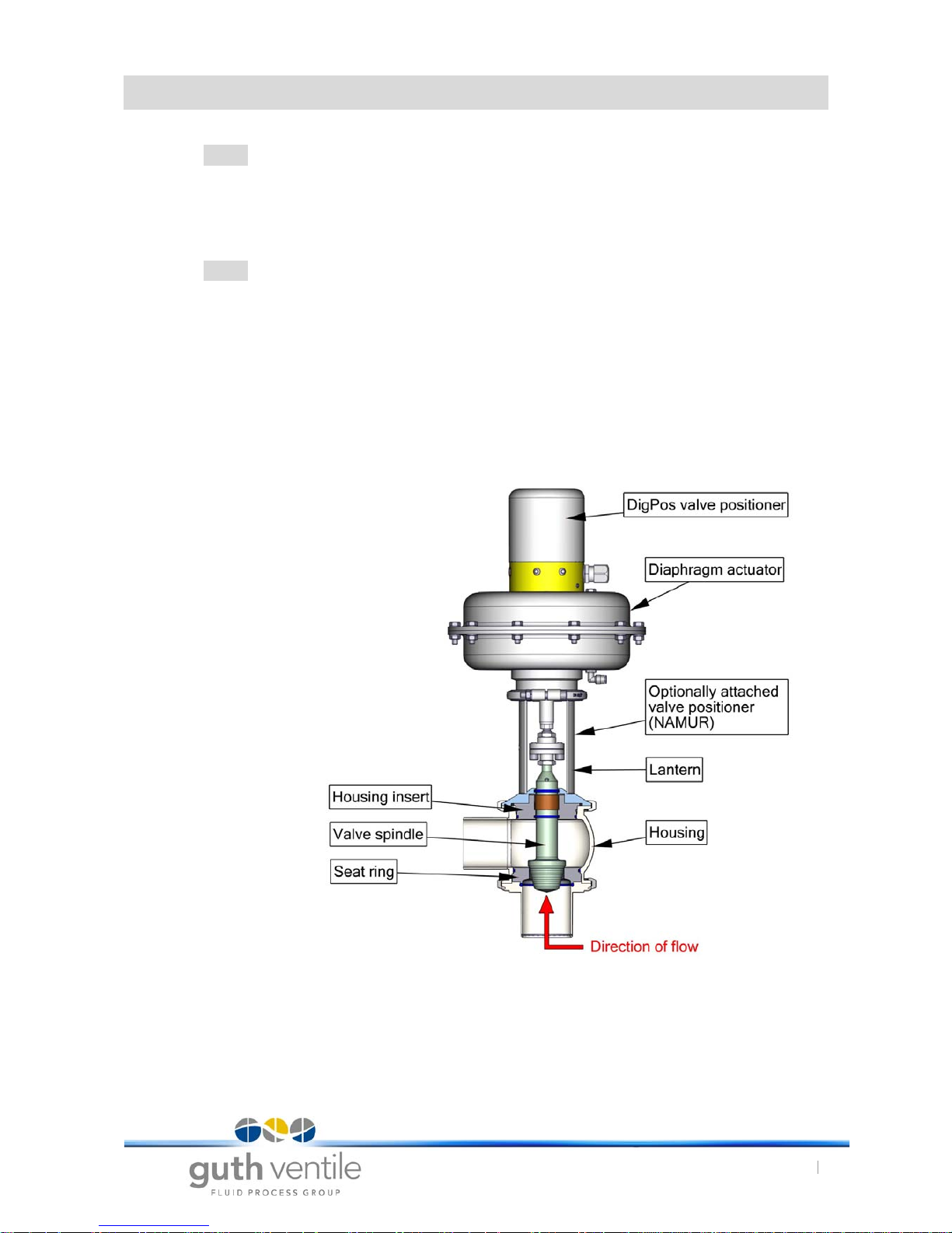
2 . 2 Design of the valve
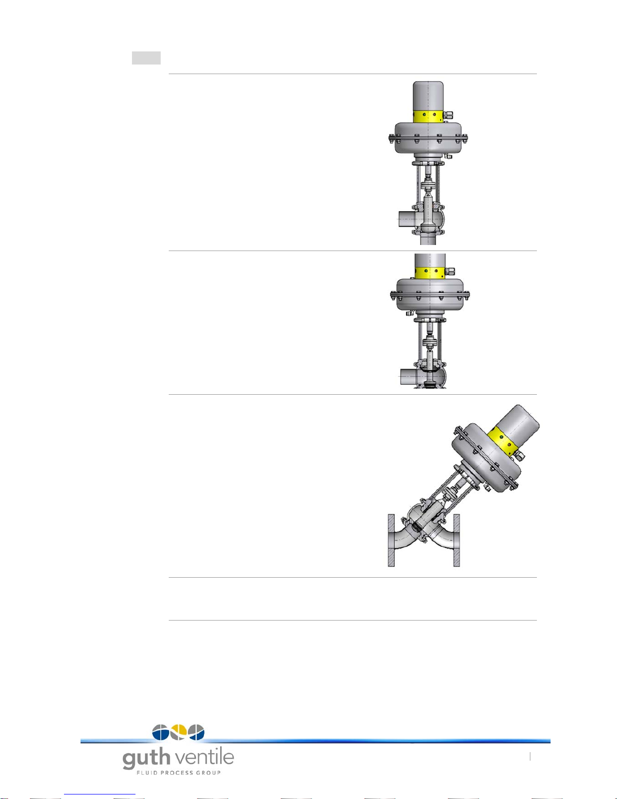
The modulating valve consists of four main sections:
a) Modulating valve housing with inner fittings according to the task
involved, consisting of a valve spindle and seat ring(s)
b) Lantern according to the task involved with spindle seal and guide.
c) Reversible stainless steel diaphragm actuator with spring return.
d) Valve positioners:- DigiPos (standard controller)
- Optionally, controller attached according to NAMUR.
Fig. 1 Modulating with DigiPos
www.sks-online.com
www.sks-webshop.com
18.4.17
Modulating Valves Type: VSR
2. Technical Data
6
2 . 3 Variants
For each of the main elements from a) to d) there are several variants available. The design is modular and they are generally mutually compatible. Exceptions to this are to be found in the steam
modulating valve, pressure reducing valve (high pressure) and aseptic diaphragm modulating valve
series on account of the valve characteristics.
2 . 4 Housing variants
A housing consists of a spherical basic body made of forged stainless steel and one or two connecting pieces with connector types according to customer requirements. On the front end of the
housings with connecting pieces the lantern can be attached, or further housing modules (with seat
ring), a blind connection or a second spindle guide. Several housing units can be coupled together
to fabricate valves with inlets and outlets on different levels with double-seat inner fittings or with
multistage control cones for reducing large pressure differences. The control cones are supplied
with a metal seal seat as standard. In special cases, however, a version with an elastomer seal can
be supplied. For special requirements, the cone and seat ring can be supplied as hardened components.
2 . 5 Lantern variants
The connection between the valve housing and the actuator is provided by the lantern b). This
serves both to guide and to seal the spindle. Here, the seal against the product space is provided
by a separate intermediate module for the upper end of the housing. The spindle is guided through
a bushing with little clearance. Where particularly high standards of hygiene must be maintained,
the chamber between the O-rings has connections for alcohol or steam. Where required on account
of difficult operating conditions, other sealing elements such as a plug socket can be installed as
well. Also, a special aseptic diaphragm and vacuum seal with Teflon-EPDM sealing elements is
available as a special module.
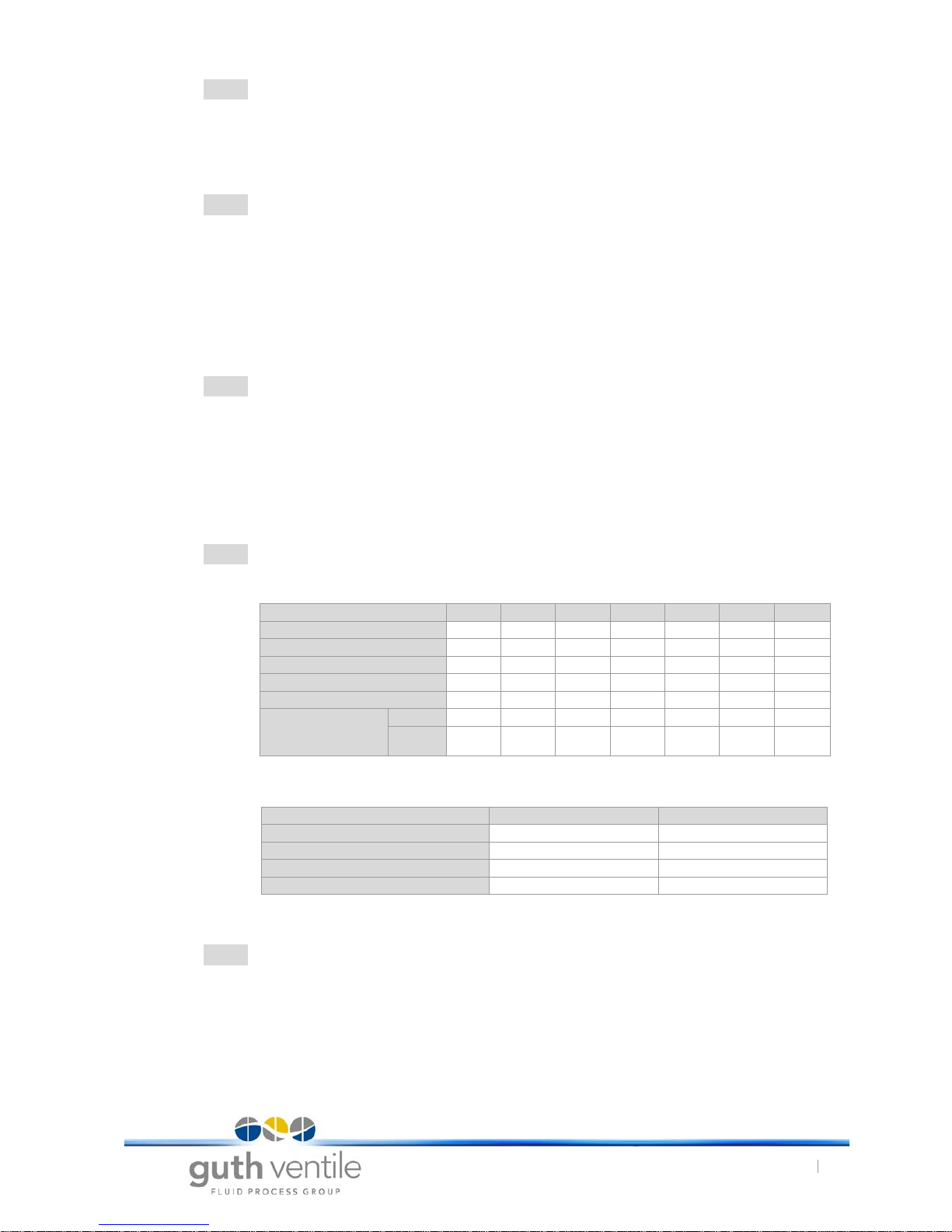
2 . 6 Actuator variants
Diaphragm actuator:
Tab. 1 Diaphragm actuators
Linear thrust actuators:
Tab. 2 Linear thrust actuators
2 . 7 Controller variants
Standard positioners:
As standard, the Guth DigiPos valve positioner is mounted on the diaphragm actuator.
Controller options:
Optionally, valve positioner according to NAMUR can be mounted.
Designation: M02 M1 M2 M3 M4 M9 M10
Travel (mm)
20 20 20 30 30 60 60
No. of springs
63636612
Setting pressure (bar)
0,8-4,0 0,8-1,5 1,5-3,0 0,7-1,5 1,5-3,0 0,7-1,5 1,4-3,0
Max. Setting pressure (bar)
6666666
Spring pre-tensioning (KN)
0,72 1,5 3,1 2,1 4,2 5,0 10,0
Closing force (KN),
air-to-close at air
pressure
4,5 bar
3,5 9,5 4,7 7,5 3,5 10,3 20,6
6,0 bar
5,4 14,3 9,5 12,2 5,3 20,5 30,8
Designation: H1 H2
Travel (mm)
25 25
No. of springs
11
Max. Setting pressure (bar)
55
Spring pre-tensioning (KN)
1,9 3,4
www.sks-online.com
www.sks-webshop.com
18.4.17
Modulating Valves Type: VSR
2. Technical Data
7
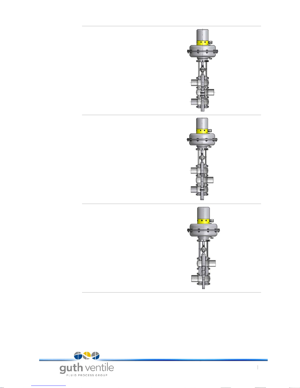
2 . 8 Valve variants
Dosage valve
VSR type L,
Cone position: K1
Dosage valve with aseptic diaphragm
VSR Type L,
Cone position: K1
Steam modulating valve
VSR Type LS,
Cone position: K1
Cone position: K2
In this position the direction of effect of
the cone is the opposite to that of K1
(change in flow direction!).
www.sks-online.com
www.sks-webshop.com
18.4.17
Modulating Valves Type: VSR
2. Technical Data
8
Mixing valve
VSR Type LLD,
Cone position: K3
Distribution valve
VSR Type LLD,
Cone position: K4
Pressure reducing valve
VSR Type LID,
Cone position: K5
www.sks-online.com
www.sks-webshop.com
18.4.17
Modulating Valves Type: VSR
3. Functional description
9
3. Functional description
The GUTH modulating valve VSR with multi-spring diaphragm actuator has a travel (stroke) of 20,
30 or 60 mm as standard for the nominal diameters DN 10 to DN 150. The linear movement of the
valve spindle is induced by means of an actuator shaft connected by a coupling piece. The diaphragm plate moves axially on account of the overpressure in the pressure chamber of the diaphragm actuator. It moves until the pressure of the compressed air on the one side is in equilibrium
with the spring load on the other side. The travel of the diaphragm plate is approximately proportional to the air pressure present, assuming that the spring has a linear characteristic curve. The air
pressure is dependent on the amount of air introduced into the pressure chamber. The principle of
operation of the valve positioner involves controlling the air supply or extraction of air by means of
a control piston. It is always possible to work with the maximum air flow rate (flow volume).
There are one or more control cones on the valve spindle that are supported by a metal seat ring.
Depending on the direction of operation of the diaphragm actuator, the spindle is either completely
raised or completely lowered when the pressure chamber is completely void. In this state, the diaphragm plate lies flush against the housing, or another limit point has been reached in the valve
housing, i.e. cone seat. However, when a cone is flush on its seat ring, it is held against it by the
pre-tensioning force.
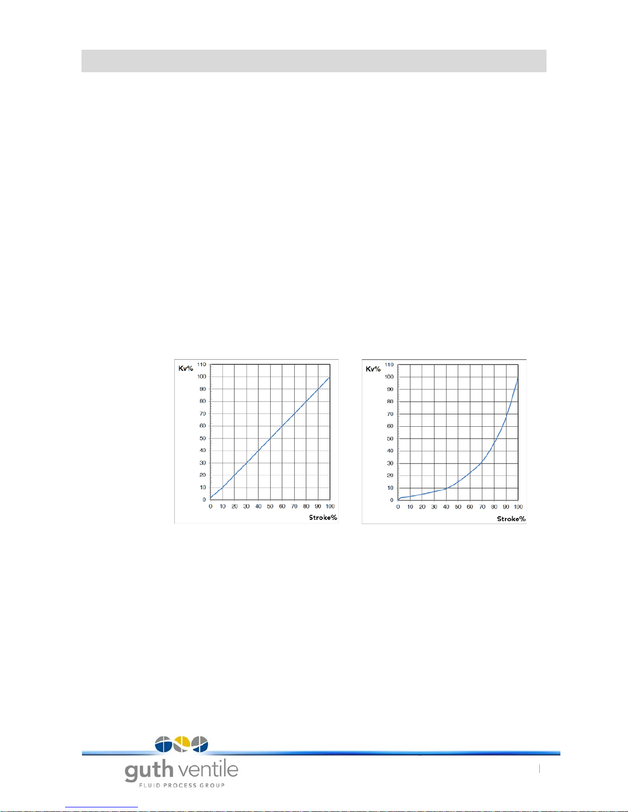
The control cones (parabolic cone) have an exactly computed form that determines the free crosssection in the ring gap in dependency on the length of travel. Depending on the flow rate reference
for the valve, the so-called Kvs value, and the desired characteristic curve as a function of the length
of travel and flow volume, different cone forms are needed. Normally, so-called linear or equal-percentage characteristic curves are used, see Figure 8. For the purpose of throttling media where
there is a high differential pressure between the inlet and outlet sides, special cone and housing
shapes are used, so-called multi-stage modulating valves.
For optimal regulation characteristics, the direction of flow must always be towards the pointed end
of the control cone.
The standard modulating valves are fitted with metal seat seals.
In this connection it should be borne in mind that leakage according to VDI/VDE 2173, and EN
1349/ IEC 60534-4 of leakage class 4 are permissible.
This means that, in view of the less stringent leakage class, modulating valves with metal seat seals
may not also be used as shut-off valves.
If more stringent leak flow restrictions are required, GUTH modulating valves with elastomer seat
seals can be used. In this case, elastomer seat rings are chambered without gaps by means of
dividing the cone in two.
As standard, the spindle seal is provided by an O-ring placed close to the product and open to flushing via a generously dimensioned gap. This represents a sensible compromise in respect of
hygiene aspects and the service life of this functional element. A second O-ring towards the spindle
seal prevents the ingress of foreign substances from outside.
Linear characteristic curve Equal-percentage characteristic curve
Diagram. 1
www.sks-online.com
www.sks-webshop.com

18.4.17
Modulating Valves Type: VSR
4. Installation of the Modulating valve
10
4. Installation of the Modulating valve
4 . 1 Installation space
The type VSR valve has a very compact design, so it can be installed practically anywhere in a
plant. However, to prevent problems arising in connection with thermal, mechanical or vibrational
issues, direct contact with other elements should be avoided. Also, the installation space for the
valve is to be dimensioned such that the fitting can easily be accessed from all sides. There must
be enough working room to allow for the removal, addition or adjustment of components.
For safety reasons, sufficient distance should be maintained to parts of a plant from which steam
or heat are released or heat is extracted so that the possibility of the temperature of the regulating
components exceeding or falling below the permitted range (approx. 0° to 70 °C) is minimized.
Especially where high process and ambient temperatures are involved, the valve should be
installed in such a way that heat can be extracted as necessary.
4 . 2 Installation of the fitting
The normal installation position for the valve is vertical, with the actuator at the top, on account of
the placement of the venting elements and in view of the way it is constructed. This position also
ensures that the product is completely evacuated from the valve housing. However, other positions
are possible (suspended, lying on its side) without the danger of the functions of components a) to
d) being impaired. Where the device is installed lying on its side and component weight presents a
problem, the actuator must be supported.
The vent valve for the spring space of the stroke piston / diaphragm actuator and the control head
should, for preference, be placed such that they are not directly exposed to spray or dripping water.
The valve must be installed in the pipe system such that it is not under tension. It is especially important in this respect to take account of forces and torques arising in the pipe system on account of
thermal expansion during operation that causes longitudinal stretching. Care must also be taken to
ensure that vibrations resulting from plant operation or the flow behaviour of the medium are not
transmitted to the valve.
Prior to assembly, the pipe geometry and the connection dimensions must be fixed according to the
installation dimensions.
On installing the valve, the components are to be inserted in the proper way. In multi-stage housings
the connections around the main valve axis are to be freely rotatable in the clamped connections
and adjusted according to the orientation of the inlet pipes.
GUTH modulating valves are precision fittings with cone seat pair tolerances of the order of 1/100
mm! In order to minimize wear on the cone and seat, we recommend installing a dirt trap or a filter
in front of the device if non-liquid or soiled media are to be transported.
In order to avoid long standstill periods, e.g on disassembling the valve for inspection purposes, we
recommend planning the plant with a shut-off fitting upstream and downstream of the valve (as
appropriate, with a bypass conduit).
4 . 3 Pipe connections
All GUTH valves can be fitted with a wide range of connectors for connection to pipe systems.
These include threaded connectors, clamped connectors, small flanges, DIN flanges as well as
pipe connecting elements according to the SMS or BS/RJT standards. Also, models with ends for
welding can be supplied. In the latter case it should be borne in mind that the entire inner fittings of
the valve as well as all the mounted components with the actuator and control head must be
removed so that welding can be done without any risk of damage to parts sensitive to heat or tension. After welding and work on the seam is complete, the parts are to be reassembled.
www.sks-online.com
www.sks-webshop.com

18.4.17
Modulating Valves Type: VSR
4. Installation of the Modulating valve
11
4 . 4 Welding seam preparation
Welding seam preparation:
The plant pipe ends to be welded are to be sawn flush and at right angles and deburred. Allign the
housing welding ends to the pipe ends (radially and axially flush align).
Prior to welding in the fitting:
The entire valve insert (actuator, lantern and spindle) is to be removed from the housing. If leakage
valves or housing inserts are present, these must be disassembled as well. During the welding work
no seals may be present next to or in the valve housing.
Welding-in instructions:
Recommended welding filler materials
Tab. 3 Examples for possible welding filler materials
Welding seam treatment:
As a rule, no reworking of the weld seam is needed inside the connecting pipe if the weld has been
carried out properly. For the outside surface of the connecting pipe, we recommend passivating the
weld seam (pickling using pickling paste).
4 . 5 Pneumtatic connection
GUTH multi-turn actuators are delivered as standard with a pneumatic connector for standard 4 mm
pneumatic hoses. In case of high ambient temperatures, a PP quality hose is recommended.
Please refer to the corresponding data sheets to obtain the required air pressure. For reasons of
functional safety and service life of the regulating device, the air quality should be high i.e. dry, deoiled and filtered to 5 µm. For oiled compressed air the quality must be according to ISO VG32
Class 1.
4 . 6 Electrical connection
Connection to be carried out according to the operating instructions of the respective control head
or electrical attachment components.
Scope of usage: Welded connections of welded-in fittings with pipes according to DIN
11850. We recommend preparing the seam according to DIN 2559.
Welding procedure: TIG (Tungsten Inert Gas welding), as appropriate using orbital welding
technique — flood pipe internally with forming gas so as to displace the
air from the welding area.
certified Personnel: To prevent damage, welding should be undertaken by certified person-
nel (EN287).
Plant part
Filler material
1.4316 1.4430 1.4404 1.4519
1.4301 x
1.4306 x
1.4401 x
1.4404 x
1.4435 x x x
1.4571 x x
CAUTION
• After welding, the valve housing must be thoroughly cleaned. Welding residue and dirt particles
can cause damage to the seals.
www.sks-online.com
www.sks-webshop.com

18.4.17
Modulating Valves Type: VSR
4. Installation of the Modulating valve
12
5. Commisioning
Normally, the GUTH modulating valve is supplied fully assembled and set according to specifications. It is assumed that the installation and connections have been carried out according to Section
4.
6. Changes to the Modulating valve
6 . 1 Changing the Kvs Value and the Flow Rate Curve
The relationship between the spindle position (travel) and the free opening cross-section at the
cone and therefore the flow volume for the liquid or gaseous medium depends on the shape and
dimensions of the cone as well as the seat diameter of the interchangeable seat ring. If a change
in the modulating range is required, then the Kvs value determines the selection of the appropriate
cone seat combination.
According to the data sheet for the GUTH modulating valve (see Section 9), several Kvs stages for
each nominal width are available. Also, there is a general distinction between cones with a linear
characteristic curves and ones with equal percentage characteristic curves.
Assemblies consisting of the seat ring and cone with spindle can be interchanged very readily as
follows:
For standard modulating valves with a simple cone seat according to cone position "K1", the
actuator with lantern can be lifted out of the housing by releasing the upper housing clamping
ring (clamping bracket). Care must be taken to ensure that the cone is not damaged by coming
into contact with other components.
For cones positioned according to "K2", the housing must be removed after releasing the pipe
connections and opening the lower clamping ring. The same applies to modulating valves with
several housing sections. There, too, a housing connection must be released at a suitable point
and the modulating valve removed from the plant after opening pipe connections. In exceptional
cases it may be necessary to leave the modulating valve installed in the plant. In such cases
at least that housing section must be removed that allows for the spindle to be withdrawn. This
is true especially for double-seat cones with cone position "K3" as well (mixer valve arrange-
ment).
Especially with modulating valves used as distribution elements with cone position 'K4', we rec-
ommend completely removing the modulating valve from the installation, as an open-ended
spanner must be used to open the spindle by unscrewing the lower cone so that the seat ring
can be removed. After the corresponding clamping connection has been released, the seat rings
can be removed manually between two housing sections or between a housing section and
pipe connecting piece. In the case of the modulating valve used as distribution element already
described above, the rings can be removed after opening the spindle where the latter is sep-
arated.
NOTICE
• To prevent the cone / seat from colliding, the actuator spindle must be aligned flush to the valve
spindle (see section 7 . 4 page 17).
www.sks-online.com
www.sks-webshop.com

18.4.17
Modulating Valves Type: VSR
4. Installation of the Modulating valve
13
The seat rings are marked with the design specification. The spindle is marked with the design
specification and the type of characteristic curve (L for linear, G for equal percentage) on the upper
part of the shaft.
After the two hexagonal bolts of the coupling piece have been released, the spindles can be
unscrewed from the coupling section on the valve side and taken out of their guides. The installation
of the same or another spindle is to be done in the reverse order, whereby the sealing elements
and the shaft surface should be covered with a thin film of a suitable grease when inserting the spindles into their guides so as to ensure smooth running at all times.
When seat rings are reinserted care must be taken to ensure that the O-rings are in perfect order.
However, we generally recommend replacing the O-rings whenever a modulating valve is opened.
The O-rings should also be greased with a thin film of suitable grease. Also, care should be taken
to ensure that the rings are properly fitted. The housing sections and the pipe connections are reassembled in the reverse order.
6 . 2 Changing the Effective Direction of the Diaphragm Actuator
Please refer to the GUTH operating and maintenance instructions for multi-spring diaphragm actuators.
CAUTION
• If the valve is in the non-actuated position, the cone and seat are pre-tensioned by the actuator.
Please make sure that the working conditions allow for clean assembly and disassembly
around the cone and seat, as these are precision parts.
www.sks-online.com
www.sks-webshop.com

18.4.17
Modulating Valves Type: VSR
7. Maintenance and repairs
14
7. Maintenance and repairs
7 . 1 Inspection
The GUTH modulating valve requires very little maintenance. Nevertheless, the regulating element
should be inspected regularly, i.e. after approx. 500 operating hours.
During the inspection, the following should be checked:
During the inspection, the following should be checked:
1. Seals of all sealing points, especially of the spindle and the pneumatic connections.
2. Modulating function of the valve, including its behaviour when the spindle is in the stationary
intermediate position.
3. Condition of the electrical connections
Re 1:
The degree of spindle sealing is indicated by means of a leakage hole for standard modulating valve
models. If the medium egresses from this leakage hole, which is to be found directly below the
clamping bracket at the junction between the upper housing and the lantern, then the spindle seal
(or seal set as appropriate) must be replaced or the valve spindle put in order.
Re 2:
Normal modulating behaviour is indicated by the spindle changing its position rapidly. In the station-
ary intermediate position, a minor oscillation around the target value may be observed. However,
more pronounced oscillation of the spindle and post-regulation of the valve positioner indicate a
fault.
Maintenance intervals:
7 . 2 Replacing the Cone-Seat Assembly
Wear induced by the medium flowing through the cone slot at high speed can alter the state of the
cone and seat in the course of time, leading to modulating behaviour that is no longer acceptable.
The wear can be slowed down by the use of modulating valves with hardened cone-seat assemblies or by reducing the flow speed (e.g. through the use of multi-stage cones), but even in such
cases the necessity to replace the cone-seat assembly at some stage must be reckoned with.
Instructions for replacing the seat ring including its sealing elements and the spindle with its sealing
elements are to be found in Section 6.1 of the operating instructions.
NOTICE
• Practical maintenance intervals can only be determined empirically by the user as they depend
on the conditions of operation involving, for instance, hours of use per day, switching frequency, type and temperature of the product, type and temperature of the cleaning agent, surrounding conditions.
www.sks-online.com
www.sks-webshop.com

18.4.17
Modulating Valves Type: VSR
7. Maintenance and repairs
15
7 . 3 Replacing the Seals
In the standard GUTH modulating valve models, all the elastomer sealing elements are O-rings
made of EPDM, HNBR or FKM. Aseptic chambered O-rings are also used as sealing elements for
elastomer sealing cones. According to their position in the valve, these can be replaced very easily
as follows:
Housing:
After releasing the relevant connection sections (clamped flange connections between the housing
modules or intermediate element or lantern), remove the old O-rings by hand or using suitable tools
and place the new O-rings in the same positions. Please take care not to damage the high-quality
sealing elements (aseptic principle) by using sharp or heavy-duty tools, and make sure that you do
not overstretch or damage the O-rings when mounting or placing them in their chambers (notches
or scratches). During installation, make sure that the new sealing element is in perfect working
order.
Spindle:
a) Standard seal
Especially where hygienic conditions are required, the spindle seal is very important. The O-rings
are replaced as described above. Make sure that the sealing surface on the spindle is in perfect
order. If it has coarse longitudinal scratches on it, the sealing surface must be smoothed using fine
emery cloth. If the surface is deeply scored, the spindle must be replaced.
b) V-ring packing (steam modulating valves)
The V-ring packing (steam packing) must be installed correctly. The O-ring of the packing must be
installed towards the product space. The PTFE pressure ring must be located on the set collar at
the top. The V-ring packing must not be too strongly tensioned in the axial direction. Therefore only
tighten the set collar lightly (by hand).
Fig. 2 Steam packing
www.sks-online.com
www.sks-webshop.com

18.4.17
Modulating Valves Type: VSR
7. Maintenance and repairs
16
c) Assembling Aseptic diaphragm unit
For the assembly of the two-section aseptic diaphragm seal, first the PTFE diaphragm is placed
towards the product space, and then the supporting EPDM diaphragm is placed behind it. The diaphragms must be placed using a mounting mandrel to prevent them getting damaged. The diaphragms are tensioned when the valve spindle component is screwed tight.
Fig. 3 Aseptic diaphragm
Mounting mandrels:
Tab. 4 Assembly tools for aseptic diaphragms
When assembling valve components, it is generally recommended to apply a thin film of grease
suitable for use with foodstuffs to the sealing elements as well as the spindle, inserts and housing
so as to ensure that the sealing elements are properly seated and long service lives for the components that slide against each other. See Section 7.5, Lubrication and Maintenance Schedule.
Fig. 4 Assembly Aseptic diaphragm
Assembly:
1. Screw together the end cap Pos.2 and
the housing Pos.3 with the clamp
connection Pos.1.
2. Install the Aseptik diaphragm unit Pos.4
in the housing.
3. Insert the adapter Pos.5 in valve spindle
Pos.4 and install it in case Pos.3.
4. Introduce the lantern Pos.6 into the
valve spindle Pos.4 and insert this on
the housing Pos.3, then screw together
with the clamp connection Pos.1.
Nominal width Designation / Article No.
DN 25-50 8105.50*3p
DN 65-100 8107.50*3p
www.sks-online.com
www.sks-webshop.com

18.4.17
Modulating Valves Type: VSR
7. Maintenance and repairs
17
7 . 4 Setting the Spindle, Coupling and Diaphragm Actuator
At the start of the setting procedure, the valve must be pre-assembled without the coupling and
actuator. The spindle must be positioned in the seat in the closed limit position.
Fig. 5 Setting the valve
The setting procedure is as follows:
1. Turn the hexagonal nuts to the end stops of the
valve and actuator spindle.
2. Turn the coupling of the valve spindle until the
centre of the coupling is at about 3 mm on the
scale of the lantern.
3. Screw the actuator spindle into the coupling while
holding the coupling firmly (for spring-travelling
actuators, this must be in the actuated limit position) until the displacement between the lantern
clamp connection and the actuator clamp connection is about 4 mm (for LLD model approx. 2
mm).
4. Now apply air to the actuator (for spring-travelling
actuators without air).
5. Now fix the lantern-actuator connection using the
clamping bracket.
6. Then set the centre of the coupling to the appropriate stroke / zero point (tolerance:
+/- 0.5 mm).
7. Put the upper hexagonal nut on the coupling.
8. The stroke / zero point can be set by supplying /
venting air to / from the actuator and using the
holes in the valve spindle (tolerance: +/- 0.5 mm).
9. Now tighten the two hexagonal nuts simultaneously.
10. To prevent the cone / seat from colliding, the
actuator spindle must be aligned flush to the
valve spindle. To this end the two Allen bolts of
the coupling must be loosened. By deploying the
valve to the open and closed positions (limit position of cone in seat), the valve spindles adjust
themselves and the Allen bolts can be retightened.
11. Finally, calibration of the travel for the valve positioner must be carried out.
www.sks-online.com
www.sks-webshop.com

18.4.17
Modulating Valves Type: VSR
7. Maintenance and repairs
18
7 . 5 Lubrication and Maintenance Schedule
7 . 6 Valve designation
Each valve carries an identification. This may be found on the actuator, lantern or housing.
Examples for identification:
310125
A) Fasten screws of the clamp connection.
B) Check bore for leaks
C) Check cone condition
D) Lubricate bearing shell with high-temerature mounting
paste.
E) Check valve seat, replace O-ring if necessary.
Fig. 6 Lubrication and maintenance
schedule
NOTICE
• Please pay attention to the lubricant manufacturer's safety data sheets!
NOTICE
• Please provide these two numbers whenever replacement parts are ordered!
VSR-#: 12/235 Kvs: 26 m3/h
Bauj. /year: 2012 Cv: gal/m
Geh. /body: VSR/L Charakt.: Gleich%
Nw/size: 50 Hub/stroke: 20 mm
- VSR 12 /235
Consecutive valve number
Year of manufacture
Valve type (abbreviation)
- 310125
Valve number corresponding to order
www.sks-online.com
www.sks-webshop.com
18.4.17
Modulating Valves Type: VSR
7. Maintenance and repairs
19
7 . 7 Cleaning and care
The valve is suitable for CIP (Cleaning in Place). The following should be borne in mind:
• Pay attention to the cleaning agent manufacturer's safety data sheets!
• The valve interior must be cleaned regularly.
• Use only cleaning agents that do not damage the valve materials.
• Use clean, chlorine-free water as a thinning agent.
• Dose the cleaning agent step-by-step and avoid using concentrations that are too high.
• After cleaning, flush with plenty of clean water.
• Ensure that the flow of cleaning agent is compatible with the process.
Recommended cleaning agents:
• NaOH = sodium hydroxide
• HNO3 = nitric acid
Example for cleaning
Example for cleaning in the food industry for process valves in version EPDM:
NOTICE
• The cleaning agents must be stored and disposed of in accordance with currently valid safety
regulations.
Cleaning step Description Exposure time
Pre-rinsing Process water at ambient temperature 15 minutes
Main cleaning I (lye step) Lye in aquaeous solution 0,5-2% by 70°C 20-30 minutes
Inter-rinsing Process water at ambient temperature 15 minutes
Main cleaning II (acid step) Acid in aquaeous solution 1-1,5% by 55°C 20-30 minutes
After-rinsing Water(drinking water quality) at ambient temperature 15 minutes
www.sks-online.com
www.sks-webshop.com

18.4.17
Modulating Valves Type: VSR
8. Malfunctions
20
8. Malfunctions
8 . 1 Mechanical valve defects (Mechanic)
The housing of the GUTH VSR modulating valve and the actuators are extremely robust, so
mechanical problems are generally not to be expected. Nevertheless, damage to the metallic surfaces and the sealing elements as well as deformation of components on account of extreme operating conditions cannot be completely excluded. The following malfunctions may occur:
1. Leakage too high for metallic sealing cone
Causes:
- The seal seat for the cone (sealing surface in the seat ring or on the cone) is damaged, e.g. by
solids, through incorrect setting of the valve spindle or actuator spindle or through erosive
effects, or in extreme cases by cavitation.
- The valve housing or spindle is deformed, so that it can no longer be precisely centred in the
conical seat.
- Deposits on the sealing surface.
- The closing pressure is no longer sufficient, e.g. because a spring has broken or the valve spindle jams or the valve housing has been assembled incorrectly or because the valve seat is worn
out.
Rectification of fault:
- If damage has occurred to the spindle, cone or seat ring the assembly must be replaced. If the
housing is deformed, this must also be replaced.
- If the spindle jams, first check the seals towards the spindle seal as well as the spindle travel
in the lantern. Check the pre-tensioning of the packing glands and the condition of the packing
elements.
- If the actuator spindle jams, open the diaphragm actuator. Please refer to the 'Operating and
Maintenance Instructions for Multi-spring Diaphragm Actuators'.
The same applies if an actuator spring has broken. Check that all guide sections are sufficiently
lubricated with a suitable lubricant.
- If deposits have built up in the area of the cone and seat ring, careful cleaning may help. However, take care to avoid causing scratches or notches on the cone or seat surfaces.
2. Flow behaviour unsatisfactory
Causes:
- Influences coming from other parts of the plant.
- Wrong cone form or model used for the process.
- Spindle or actuator do not travel smoothly.
- Damage to cone or seat ring.
- Seat ring and spindle out of true, e.g. because they have been installed incorrectly or the spindle has become deformed or it has too much play.
- The valve positioner does not work properly.
Rectification of fault:
- If damage has occurred to the cone-seat assembly, we generally recommend replacing it in
accordance with Section 6.1.
- If the actuator spindle jams, open the diaphragm actuator. Please refer to the "Operating and
Maintenance Instructions for Multi-spring Diaphragm Actuators".
The same applies if an actuator spring has broken. Check that all guide sections are sufficiently
lubricated with a suitable lubricant.
- If the modulating properties are not satisfactory for some reason associated with the plant,
checks should be made in appropriate cases as to whether another cone form, a different Kvs
value or other measures can improve the situation.
www.sks-online.com
www.sks-webshop.com

18.4.17
Modulating Valves Type: VSR
8. Malfunctions
21
3. Housing leaks
Causes:
- From time to time, leakage may occur through the influence of flow forces or (fluctuating) pressure and temperature influences on the static elastomer sealing elements (O-rings) of the
housing, or through ageing. Please also check the compatibility of the sealing material used
with the media processed by the plant.
Rectification of fault:
- Replace the sealing elements. Please check whether the seal chambers are still in perfect condition. Especially the seal chamber between two housing modules (aseptic sealing principle) is
a very sensitive component on account of the way it is constructed. It must be free of notches
and other damage.
4. High noise levels
Causes:
The turbulent flow of the medium in the ring gap causes vibrations, especially of the valve spindle,
but also of the valve housing. Such vibrations also get transmitted to parts of the fitting that are further away from the origin. At certain locations it is even possible that extreme vibrations, and therefore noise, are generated through resonance effects. With the use of especially robust (rigid)
housings and spindles and precise spindle guides, noise problems with GUTH modulating valves
can generally be prevented.
Causes:
- Inadmissible pressure difference at the cone.
- Unsuitable dimensioning of the valve.
- Fine gaps between the cone and the seat, e.g. because of wear, deformation, poor fit, wrong
setting of the spindle (spindle coupling), deposits.
- Too much play in the spindle guide.
- Loose connecting elements.
Rectification of fault:
- Under extreme operating conditions special measures may need to be taken (e.g. multi-stage
cones). In certain cases a double spindle guide may help.
- In such cases please contact the GUTH company directly.
- Where noise is caused by worn parts, these must be replaced.
- Loose connection or clamping elements (e.g. clamping brackets) should be tightened or
replaced as appropriate.
- Insertion of a perforated screen (for hygienic reasons, only to be used for steam modulating
valve).
8 . 2 Defects on the actuator
1. Valve no longer maintains the product pressure
Causes:
- Broken springs.
- Leaking / Ruptured diaphragm.
- Insufficient air pressure.
Rectification of fault:
- Replacement of springs or diaphragm; see "Operating and Maintenance Instructions for Multispring Diaphragm Actuators".
- Tightening of the screw connections of the actuator housing.
www.sks-online.com
www.sks-webshop.com

18.4.17
Modulating Valves Type: VSR
8. Malfunctions
22
2. The valve stroke is incomplete
Causes:
- Leaking / Ruptured diaphragm.
- Hexagonal nut of the actuator shaft is loose.
- Actuator shaft jammed.
- Valve spindle stiff.
- Controller defect.
- Setpoint signal false or maladjusted, e.g. from signal splitting.
- Zero point setting false.
- Spindle wrongly set.
Rectification of fault:
- Please refer to the corresponding operating instructions.
www.sks-online.com
www.sks-webshop.com

18.4.17
Modulating Valves Type: VSR
9. Transport, Packaging and Disposal
23
9. Transport, Packaging and Disposal
9 . 1 Transport and Packaging
Prior to transport, the valves are carefully checked and packed. However, the possibility of damage
during transport cannot be excluded.
Unpacking:
Remove the protective caps from the pipe connections (if present) and any remaining packaging.
Receiving inspection:
Check the received goods against the delivery note to ensure that no parts are missing!
If damage is discovered:
Check the delivery for damage (visual inspection)!
In case of complaint:
If the delivery has been damaged in transit:
- Get in touch immediately with the last shipper!
- Keep the packaging (in case the shipper wishes to inspect it or for returning the goods).
Packaging for returning goods:
If possible, use the original packaging material.
- If queries arise in connection with packaging and transport safety please contact Guth Ventiltechnik GmbH.
Storage in open air:
Storage in the open air is not permitted.
Storage in closed spaces:
Storage conditions:
- Temperature: 0°C bis 30 °C
- Humidity (air): < 60 %
9 . 2 Disposal
The valves are made mainly of steel (with the exception of electrical components and seals). They
are to be disposed of according to locally valid environmental protection regulations.
Cleaning agents must be disposed of in accordance with local regulations and the manufacturers'
instructions on the safety data sheets.
www.sks-online.com
www.sks-webshop.com
18.4.17
Modulating Valves Type: VSR
10. Data sheet for GUTH Modulating valves
24
10. Data sheet for GUTH Modulating valves
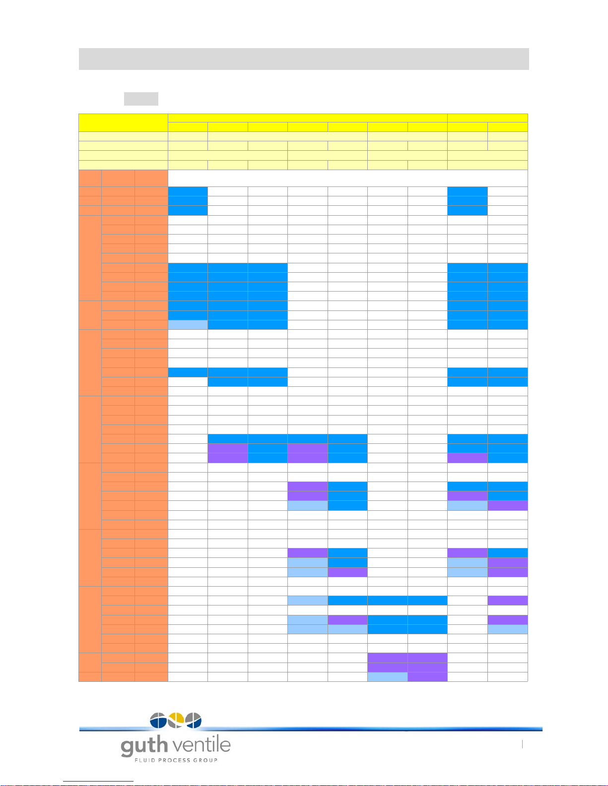
10 . 1 Spring-to-close, Valve model series Type L
Tab. 5 Data sheet for modulating valves, spring-to-close
Actuator type
Diaphragm actuator Linear thrust actuator
M02 M1 M2 M3 M4 M9 M10 H1 H2
Actuator surface
128 320 720 74 129
Setting pressure (bar)
0,8-4,0 0,75-1,5 1,5-3,0 0,7-1,5 1,5-3,0 0,7-1,5 1,4-3,0 2,5-5,0 2,5-5,0
Travel (mm)
20 30 60 25
No. of springs
6 3 6 3 6 6 12 1
DN
Kvs
(m3/h)
Seat-Ø
(mm)
10 0,1 6 16 16
15 1 7 16 16
20 1,6 8,5 16 16
25
0,25 4
0,4 5
0,63 6
1 7
1,6 8,5
2,5 11 16 16 16 16 16
4 16 16 16 16 16 16
7 19 16 16 16 16 16
9 24 11 16 16 16 16
32
7 19 16 16 16 16 16
11 24 11 16 16 16 16
15 32 6 16 16 16 16
40
0,1 5
2,5 11
4 16
7 19
11 24 11 16 16 16 16
18 32 16 16 16 16
26 37
50
2,5 11
4 16
7 16
11 24
18 32 12 16 12 16 16 16
26 37 8,4 16 8,4 16 16 16
28 48 7,7 16 7,7 16 9,1 16
65
7 19
18 32
26 37 8,4 16 16 16
43 48 7,7 16 9,1 16
50 62 4,4 11 5,1 8,9
56 66
68 62
80
18 32
26 37
43 48 7,7 16 9,1 16
68 62 4,3 11 5,1 8,9
85 73 2 7,9 3,4 6,4
100 73
100
43 48
68 62 4,3 11 16 16 8,9
85 73
100 73 2,9 7,9 16 16 6,4
120 90 1,7 5 14 16 3,8
150 90
180 96
125
150 90 10 10
260 115 7,8 10
150 380 135 5,5 8,2
www.sks-online.com
www.sks-webshop.com
18.4.17
Modulating Valves Type: VSR
10. Data sheet for GUTH Modulating valves
25
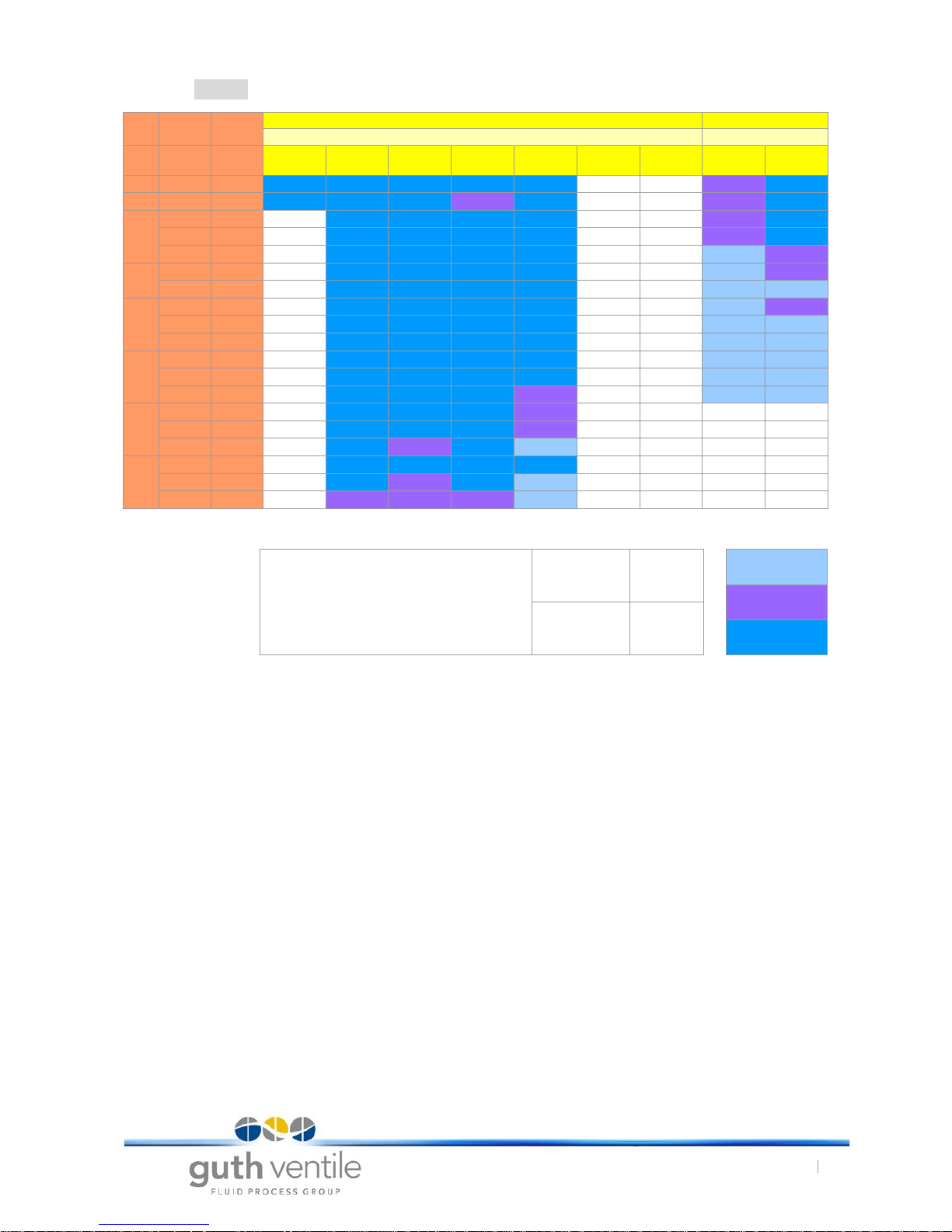
10 . 2 Air-to-close (Air pressure 6bar) Valve Model Series Type L
Tab. 6 Data sheet for modulating valves, air-to-close (calculated values)
Diaphragm actuator Linear thrust actuator
P max (bar) P max (bar)
DN
Kvs
(m3/h)
Seat-Ø
(mm)
M02 M1 M2 M3 M4 M9 M10 H1 H2
32 15 32 16 16 16 16 16 9 16
40 18 32 16 16 16 9 16 9 16
50
18 32 16 16 16 16 9 16
26 37 16 16 16 16 6,7 14,8
28 48 16 16 16 16 4 8,8
65
43 48 16 16 16 16 4 8,8
50 48 16 16 16 16 2,4 5,3
80
43 48 16 16 16 16 4 8,8
68 62 16 16 16 16 2,4 5,3
85 73 16 16 16 12,6 1,7 3,8
100
68 62 16 16 16 12,6 2,4 5,3
100 73 16 16 16 12,6 1,7 3,8
120 90 16 16 16 8,3 1,1 2,5
125
100 73 16 16 16 8,3
150 90 16 16 16 8,3
260 115 13,6 8 11,7 5
150
150 90 16 16 16 12,6
260 115 13,6 9 11,7 5
380 135 9,9 6,6 8,5 3,7
NOTE
Maximum permitted product pressure
DN 25-100 16 bar
von 1 - 6 bar
bis 10 bar
DN 125-150 10 bar
über 10 bar
www.sks-online.com
www.sks-webshop.com

18.4.17
Modulating Valves Type: VSR
11. Technical Information
26
11. Technical Information
11 . 1 Fields of application and materials
11 . 2 Tightening torques
The table contains non-binding guide values that apply to bolts and nuts according to DIN 912, 931,
933 and 934/ ISO 4762, 4014, 4017, 4032 of stainless steels A2 and A4.
They assume a coefficient of friction of µ=0.12 for standard bolts and nuts without lubrication.
The tightening torques specified here may only be taken as very rough and non-binding, approximate values (see VDI 2230).
Tab. 7 Tightening torque
Standard valve
Working temperature:
Sterilization temperature:
min. +1°C to max. +90°C
max. +140° C
Steam modulating valve
Working temperature:
max. +150° C
Sealing material
Working temperature:
Operating temperature
(depends on the sealing material)
Maximum internal housing pressure (Standard)
DN 25-100/ OD 1“-4“:
DN125-150/OD 5,5“-6“:
max. PN 10
max. PN 6
Material / Surface quality (Standard):
Parts in contact with product:
other parts:
(others optionally on request)
1.4301(AISI 304)
1.4404 (AISI316L)
1.4301 (AISI 304L)
Surfaces in contact with product: Ra 0.8
Gaskets, in contact with product: EPDM, HNBR, FKM, FEP, FFKM, PTFE
NOTICE
• Test resistance to media, cleaning agents and temperature!
NOTICE
• Additional lubrication of the thread substantially changes the friction coefficient and results in
non-definable tightening ratios!
Strength class 50
'e.g. rotating parts'
Strength class 70
'Standard A2-70, A4-70'
Strength class 80
'e.g. A4.80'
Thread
Tightening torque
in Nm
Tightening torque
in Nm
Tightening torque
in Nm
M 5 1.7 3.5 4.7
M 6 3.0 6.0 8.0
M 8 7.1 16.0 22.0
M 10 14.0 32.0 43.0
M 12 24.0 56.0 75.0
M 16 59.0 135.0 180.0
M 20 114.0 280.0 370.0
M 24 198.0 455.0 605.0
M 30 193.0 1050.0 1400.0
www.sks-online.com
www.sks-webshop.com

Konformitätserklärung /
Declaration of Conformity /
Deklaracja zgodnoś ci
www.sks-online.com
www.sks-webshop.com
 Loading...