

GUTHRIE & FREY GF24, GF40, GF50 Installation, Operation And Maintenance Manual

‘GF’ Series
Water Softener
INSTALLATION, OPERATION,
AND MAINTENANCE MANUAL
COMPLETE FOR FUTURE REFERENCE:
MODEL NO:
SERIAL NO:
DATE INSTALLED:
DEALER:
8-569 G&F R2

LIMITED WARRANTY
FOR W A TER CONDITIONERS AND FIL TERS
LIMITED WARRANTY
Pressure Vessel - TEN YEARS
Manufacturer guarantees to the original consumer buyer that the water conditioner or filter fiberglass pressure vessel
will not rust, corrode, leak or burst during the first ten years of original installation, provided that the conditioner or filter
is installed in accordance with manufacturers’ printed instructions and is not subjected to water pressure
exceeding 125 psi and/or water temperature exceeding 120
misuse, alteration, neglect, freezing, fire or accident, and further providing the vessel is not damaged by an act of nature
such as, but not limited to, a flood, hurricane or tornado.
If during the first ten years of original installation the pressure vessel proves, after inspection by Manufacturer, to be defective in material or workmanship, Manufacturer will furnish to the original consumer buyer a new replacement vessel
without charge. You pay freight one way and local labor charges. No allowance is made for consequential
damage, labor, or expense incurred as a result of proven defect.
Brine Tank, Brine Cabinet, or Solution Container - FIVE YEARS
Manufacturer also guarantees to the original consumer buyer, that the water conditioner brine tank or brine cabinet or
filter chemical solution container, to be free from defects in material or workmanship for five years after original installation provided that the brine tank, cabinet, or solution container is not subjected to misuse, alteration, neglect, freezing,
fire or accident, and further providing the same is not damaged by an act of nature such as, but not limited to, a flood,
hurricane, tornado, or ultra-violet ray attack.
If during the five year period the brine tank, cabinet, or solution container proves, after inspection by Manufacturer, to
be defective in materials or workmanship, Manufacturer, will replace the same with a new brine tank, cabinet, or solution container without charge. You pay freight one way and local labor charges. No allowance is made for consequential
damage, labor, or expense incurred as a result of proven defect.
o
F, providing further that the vessel is not subjected to
Valve Module - FIVE YEARS
Manufacturer also guarantees to the original consumer buyer that the water conditioner or filter, noryl plastic
module valve or brass valve to be free from defects in material and workmanship for five years after original installation.
If during this five year period the valve module proves, after inspection by Manufacturer, to be defective in materials
or workmanship, Manufacturer will replace or, at Manufacturer’s sole option, repair the same without charge. You pay
freight one way and local labor charges. No allowance is made for consequential damage, labor, or expense incurred as
a result of proven defect.
General Provisions
Manufacturer assumes no responsibility with respect to any portion of these warranties in the event of abuse, misuse or
negligence by the original consumer buyer or for failure to meet the terms of these warranties caused by strikes,
government regulations, material shortages or circumstances beyond Manufacturer’s control.
The warranties set forth herein are contingent upon receipt by Manufacturer of written notice of any defect within thirty
days after the same is discovered and upon the proper installation and operation of the water conditioner in
accordance with factory specifications and applicable plumbing codes and ordinances. Manufacturer’s sole obligation
under these warranties is to repair or replace the component or part in question which proves to be defective in material
or workmanshipwithin the time periods specified. Manufacturer IS NOT LIABLE FOR CONSEQUENTIAL OR INCIDENTAL
DAMAGES. No Manufacturer dealer, agent, representative, or other person is authorized to alter, extend or to expand
these warranties.
THE EFFECTIVE PERIODS OF ANY APPLICABLE IMPLIED WARRANTIES ARE LIMITED TO THE EFFECTIVE PERIODS
OF THE WRITTEN WARRANTIES AS SPECIFIED HEREIN. This warranty gives you specific legal rights and you may also
have other rights which vary from state to state.

“GF” SERIES AUT OMA TIC W ATER CONDITIONERS
TABLE OF CONTENTS
SYSTEM INFORMATION
Specication Table ........................................................................................................................................................1
INSTALLATION
Installation Diagram .......................................................................................................................................................2
Installation Fitting Assemblies .......................................................................................................................................3
Installation Procedures .................................................................................................................................................4
OPERATION
Control Valve Function and Cycles of Operation ..........................................................................................................7
Control Valve Programming .......................................................................................................................................... 8
Flow Diagrams ............................................................................................................................................................12
Bypass Valve Operation ..............................................................................................................................................13
MAINTENANCE
Valve Assembly ...........................................................................................................................................................14
Injector ........................................................................................................................................................................16
Brine System and Tank ................................................................................................................................................18
Water Meter and Meter Plug .......................................................................................................................................19
Bypass Valve Parts ..................................................................................................................................................... 20
Fittings ........................................................................................................................................................................21
Troubleshooting ...........................................................................................................................................................22
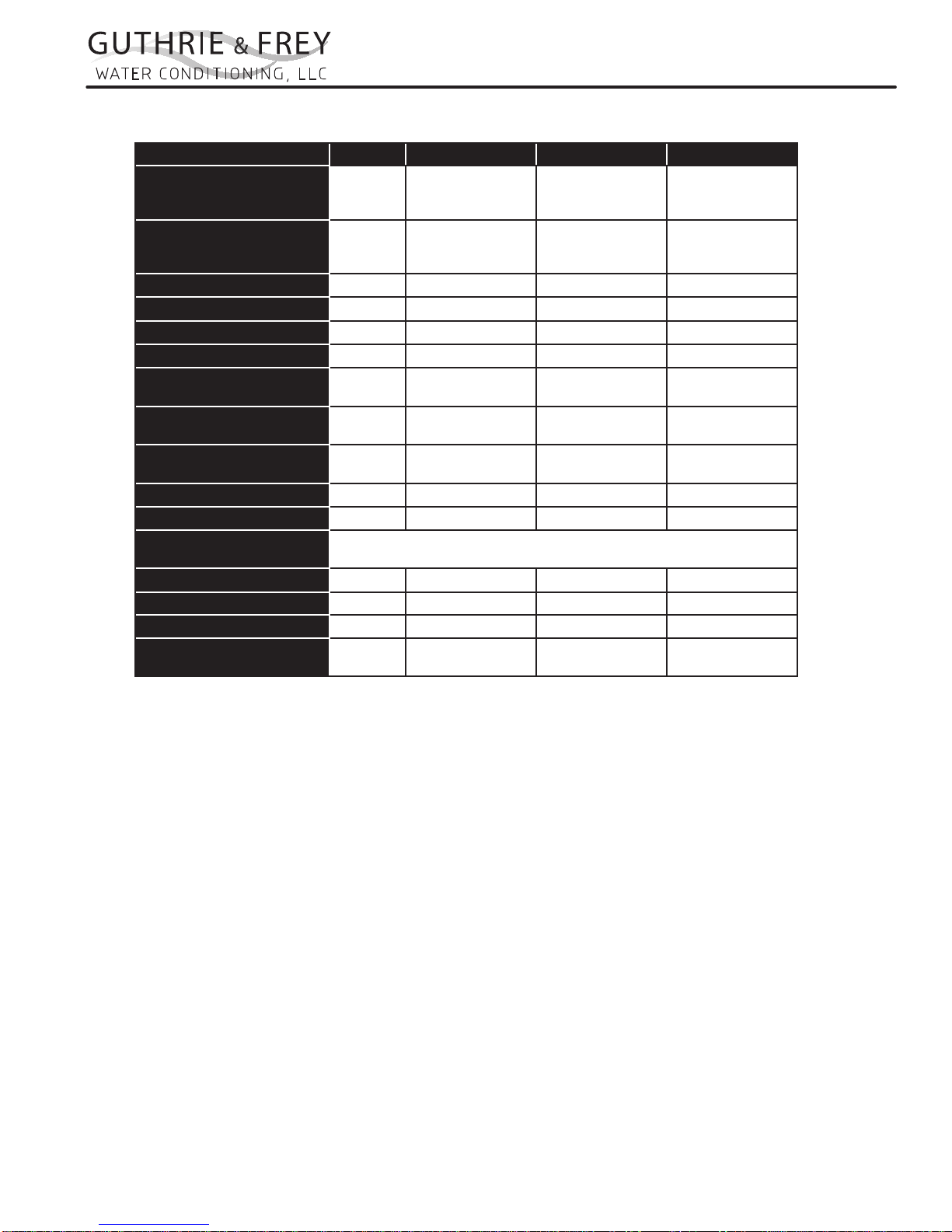
Specications
MODEL NUMBER UNITS GF24 GF40 GF50
EXCHANGE CAPACITY
(KILOGRAINS)
SALT PER REGENERATION
(LBS. / REGEN)
MAX SERVICE FLOW (1) GPM
PIPE SIZE - IN/OUT INCHES
DRAIN SIZE INCHES
OPERATING PRESSURE MAX PSI
OPERATING TEMPERATURE
MAX
MINERAL TANK SIZE
(DIA. X HT.) (2)
BRINE TANK SIZE
(DIA. X HT.) (3)
SALT STORAGE LBS.
RESIN VOLUME CU. FT.
ELECTRICAL (VOLTAGE,
CYCLE)
SHIPPING WEIGHT LBS.
FLOOR SPACE INCHES 27x18 28x18 31x18
OVERALL HEIGHT INCHES 52 55 60
MAX FLOW TO DRAIN
DURING REGENERATION (4)
“GF” SERIES AUT OMA TIC W ATER CONDITIONERS
SYSTEM INFORMATION
MAX
MID
MIN
MAX
MID
MIN
DEG F 110 110 110
INCHES 8X44 10x47 12x52
INCHES 18x40 18x40 18x40
GPM 1.7 2.2 3.2
24,030
21,020
17,120
11.5
7.5
4.5
13.2 14.7 19.1
1 1 1
3/4 3/4 3/4
125 125 125
450 450 450
0.75 1.3 1.6
120 Volts 60 Hz
72 106 137
41,650
36,175
29,560
19.5
13.0
8.0
51,260
44,500
36,350
24.0
16.0
9.5
(1) Pressure drop at 15 psi.
(2) Pressure vessels are seamless and made of reinforced fiberglass, pressure-tested at 300 psi.
(3) Brine tanks are fabricated of seamless, rigid, tough, high-impact, non-toxic polyethylene.
(4) 50 psi inlet pressure.
NOTE: This water softener is not intended to be used for treating water that is microbiologically
unsafe or of unknown quality without adequate disinfection before or after treatment.
1
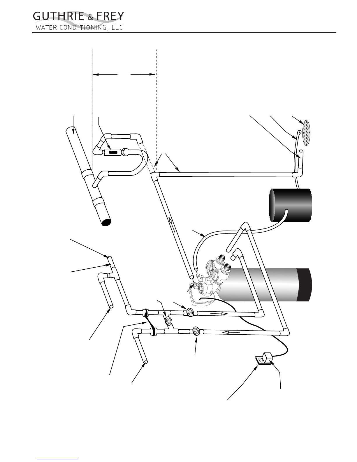
Assembly
Assembly
Maximum drain pipe
elevation above drain
Connection to sanitary sewer line
(optional)
Sanitary sewer line
Air gap device
port is 5 ft.
“GF” SERIES AUT OMA TIC W ATER CONDITIONERS
INSTALLATION
Sanitary Drain, Floor Drain or
Laundry Tubs are acceptable.
Do not make a direct connection
to the drain. An air gap must
be present.
Drain
Brine Tank Overflow drain 1/2”
diameter minimum size
Drain line 1/2” diameter
minimum size
(gravity flow)
Drain Trap
Cold hard water inlet
30 p.s.i. minimum pressure
1/2” minimum pipe size
High Pressure Warning:
If feedwater pressure is known to be above
100 p.s.i. it is strongly recommended that a
pressure reducing valve be installed at this point.
Manual Bypass Valve
(Normally Closed)
(optional)
Manual Inlet Valve
Drain Port
(optional)
Softener Tank
Brine Line Tubing
Brine Tank
Typical Water Softener Installation
Hard water to Sprinklers and any
dersired unsoftened fixtures
Ground Strap
Softened Water Outlet
Manual Outlet Valve
(optional)
110-125 Volt
Continuous Power Supply
Transformer
2

“GF” SERIES AUT OMA TIC W ATER CONDITIONERS
INSTALLATION
Installation Fitting Assemblies
1. Installation ttings connect to the control valve or the bypass valve using nuts that only require hand tightening.
Hand tightened nut connections between control valve and installation ttings, control valve and bypass valve, and
bypass valve and installation ttings allow for ease serviceability. Do not use a pipe wrench to tighten nuts on
installation ttings. Hand tighten only.
2. Split ring retainer design holds the nut on and allows load to be spread over the entire nut surface area reducing
the chance for leakage. The split ring design, incorporated into the installation ttings allows approximately 2
degrees off axis alignment to the plumbing system. The installation ttings are designed to accommodate minor
plumbing misalignments but are not designed to support the weight of a system or the plumbing.
3. When assembling the installation tting package, connect the tting to the plumbing system rst and then attach the
nut, split ring and o-ring. Heat from soldering or solvent cements may damage the nut, split ring or o-ring. Solder
joints should be cool and solvent cements should be set before installing the nut, split ring and o-ring. Avoid getting
primer and solvent cements on any part of the o-rings or split rings, bypass valve or control valve. Solvent cements
and primers should be used in accordance with the manufacturer’s instructions.
Slip the nut onto the tting rst, then the split ring second and the o-ring last. hand tighten the nut. If the tting
is leaking, tightening the nut will not stop the leak. Remove the nut, remove the tting, and check for damage or
misalignment of the o-ring.
Do not use the pipe dope or other sealant on threads. Teon tape must be used on the threads of the 1”
NPT elbow and the 1/4” NPT connection and on the threads for the drain line connection. Teon tape is not
necessary on the nut connection or caps because of o-ring seals.
Do not use Vaseline, oils or other hydrocarbon lubricants oanywhere on the control valve or resin tank
assembly. A silicon lubricant may be used on black o-rings, but is not necessary.
Bypass Valve
1. The bypass valve easily connects to the control valve body using nuts that only require hand tightening. Hand
tighten nut connections between control valve and ttings, control valve and bypass valve, and bypass valve and
installation ttings allow for easy serviceability. The split ring retainer design holds the nut on and allows load to
be spread over the entire nut surface area reducing the chance for leakage. The split ring design, incorporated into
the bypass, allows approximately 2 degrees off axis alignment to the plumbing system. The bypass is designed to
accommodate minor plumbing misalignments but is not designed to support the weight of a system or the plumbing.
Avoid getting primer and solvent cements on any part of the o-rings or split rings, bypass valve or control
valve. Do not use pipe dope or other sealant on threads. Teon tape is not necessary on the caps because of
o-ring seals.
Do not use Vaseline, oils or other hydrocarbon lubricants oanywhere on the control valve or resin tank
assembly. A silicon lubricant may be used on black o-rings, but is not necessary.
Connecting Fittings
CAUTION: Care must be used when working with copper tubing. Do not allow the ame from torch to contact any por-
tion of the Valve assembly.
1. Attach 1/2” drain line to drain elbow with insert and nut. Use optional 3/4” drain ttings if drain run
exceeds 25 ft.
2. Do not elevate the drain line over 5’ above the top of the valve (8’ on municipal systems) or to exceed 25’ in
length at either height.
CAUTION: An air gap must be provided upon sewer entry. (Conform to local plumbing and sanitation codes and ordi-
nances).
3. The salt storage cabinet or brine tank provides an overow. Attach 1/2” ID exible plastic tubing to the overow
tting and direct it to the drain. DO NOT connect to the main drain line. Use a separate gravity ow line.
3
“GF” SERIES AUT OMA TIC W ATER CONDITIONERS
INSTALLATION
Installation Procedures
Please see page 3 for installation of tting assemblies.
All installation procedures must conform to local plumbing, electrical and sanitation codes and ordinances.
A. Planning Installation
1. It is recommended that outside faucets for lawn
service be on a hard water line, ahead of the softener. This will conserve softened water, save salt
www.Marlo-Inc.com
and prevent lawn damage. If this is not practical,
use the convenient integral bypass valve assembly
during irrigation ows.
2. CAUTION: The inlet water temperature MUST
NOT EXCEED 110° F.
3. DO NOT locate the softener where ambient temperature drops below 40° F.
4. Allow space around the softener for ease of servicing.
5. Softener drain lines must never be solidly connected to the sewer line (always provide an air gap
at the END of the drain line).
6. The drain line must NOT be elevated over 5’ from
the top of the softener on well systems, and 8’ on
municipal water systems.
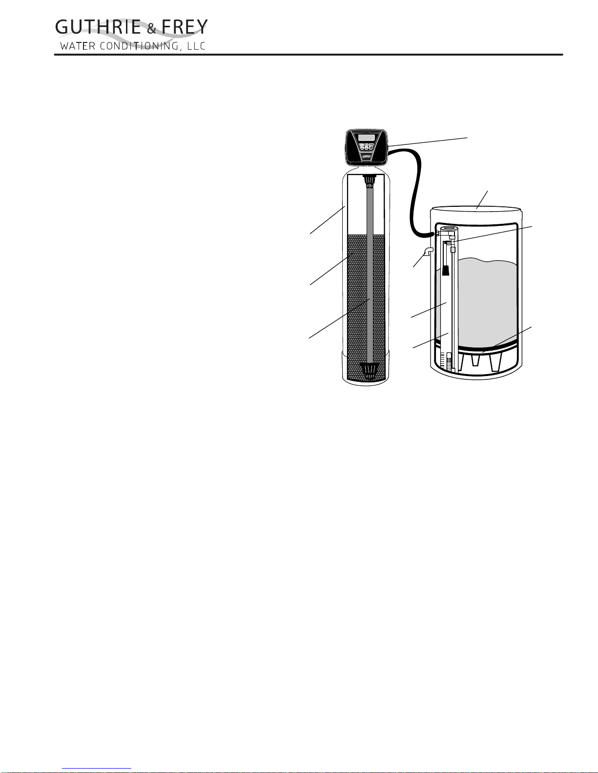
Resin
Tank
Ion
Exchange
Media
Distributor
Tube
Assembly
Overflow
Drain
Brine
Well
Air
Check
7. Drain line must not extend more than 20’ in length.
If longer runs are required increase the drain size
to 1”.
8. The brine tank or salt storage cabinet is a gravity drain. This drain line must be lower than the drain tting on
the side wall of the brine tank or cabinet.
Control
Valve
Brine Tank
Safety
Brine
Valve
Brine
Grid
Plate
B. General Installation
1. Turn off the main water supply before making any plumbing connections to existing piping.
2. Move the softener into position, making sure it is on a clean level surface. If shims are needed you may use
those to create a level installation. DO NOT USE METAL SHIMS
3. When installing the unit, be sure to connect the inlet and outlet to the correct ports on the valve. The bypass
valve and the control valve are both marked with arrows that indicate the direction of water ow. If water lines
are reversed resin maybe forced from the water softener and into household plumbing system. Should this
occur, the plumbing system would need to be ushed.
4. Install the bypass valve assembly. The control valve is designed to accommodate minor plumbing misalignments. It is not designed to support the weight of the unit.
5. Please see page 3, item 3 for assembling and soldering of ttings.
6. Install an appropriate grounding strap across the inlet and outlet piping of the water conditioning system to
ensure that a proper ground is maintained.
7. Move the brine tank into place. Making sure that the oor is clean of any debris. Sharp objects such as rocks
can cause punctures to the brine tank over a period of time. This would not be covered under Marlo’s warranty.
(DO NOT ADD SALT AT THIS TIME).
8. Connect one end of the brine line (brine line is located inside the brine tank. Marlo units come with 5’ of brine
line) to the brine elbow of the brine tank and the other end to the brine elbow on the control valve. The brine
elbow on the control valve is black in color and located on the top of the control valve. The brine elbow swivels
to allow the brine tank to be placed in a convenient position.
9. The drain line connector is located on the top of the control valve and is black in color. The water softener comes
standard with 5/8 insert and nut if installer is using a poly tube. The drain elbow is threaded, so a ¾” drain line
may also be used. NOTE: If soldering the drain line use caution so as not to cause damage to the drain elbow.
4

“GF” SERIES AUT OMA TIC W ATER CONDITIONERS
INSTALLATION
10. An overow tting is attached to the outside of the brine tank (overow elbow is white in color). Attach a 5/8
drain line (do NOT connect overow tubing with drain line tubing). The overow tting is installed in case the
unit would malfunction and water would continually run to the brine tank. The overow (if tubing is connected)
would allow the excess water to be run to the drain rather than overow onto the oor. Do NOT run overow
tubing above the overow elbow at any point.
C. Installation and Start Up
1. Make sure all connections have been made: Inlet, outlet, brine line installed and connected to the brine tank
and control valve, drain line installed, and over ow drain tubing connected and run to the drain. (DO NOT
CONNECT DRAIN LINE AND OVERFLOW TUBING)
2. If the unit is not in bypass please do so now. If using a bypass purchased with the unit the unit will be in the
bypass position when the two arrows on the handles of the bypass are pointing towards each other (see gure
2 page 12).
3. Turn on your main water supply. Locate a cold soft water tap and turn it on, allow the water to run until all excess air and foreign material is removed from the water.
4. Add seven (7) gallons of water to the brine tank.
5. Plug the water softener into the designated receptacle. Program the current time of day (see page 9 for instructions).
6. Press and hold the REGEN button (located in the upper right hand corner) until the unit starts a regeneration
(depending on how the unit is programmed the rst cycle may be back wash or brine ll). Once the piston
stops moving and the unit is counting down press the REGEN key again. This will advance the unit to the next
cycle. Repeat this process until you see the word RINSE in the upper left hand corner. Slowly open the inlet
side of the bypass (see page 13 gure 3). Let the water run to the drain until the water runs clear.
7. Place the bypass back into the bypass mode (see page 13 gure 2)
8. Press the REGEN button again to cycle the unit to the next cycle. Wait for the piston to stop moving and press
the REGEN button again. Repeat this until the unit is at the home screen. The home screen will be blue in
color.
9. Press and hold the REGEN button again until the unit starts a regeneration. Depending on how the unit it set
up you might have to wait for the piston to stop moving and press the REGEN button again repeating several
times till the word BACKWASH appears in the upper left hand corner. On most units BACKWASH should appear at the rst screen.
10. Slowly turn the handle of the incoming water (See page 13 gure 3) until the bypass valve is completely
opened. Once you have a solid ow of water to the drain, open the outlet side of the bypass (see page 13
gure 1) to duplicate the normal operation.
11. Press the REGEN button again to cycle the unit to the next cycle. Wait for the piston to stop moving and press
the REGEN button again. Repeat this until the unit is at the home screen. The home screen will be blue in
color.
12. Set the incoming hardness of the water, time of regeneration and calendar override. See page 8 Steps 1I
through 6I.
13. Add salt to brine tank.
5

“GF” SERIES AUT OMA TIC W ATER CONDITIONERS
INSTALLATION
D. Manual Regeneration
The user can initiate manual regeneration.
Pressing and holding the REGEN button for approximately 3 seconds will immediately start the regeneration. The
user cannot cancel this request.
NOTE: Program Timer “Lockout” Feature
The Program Timer is initially set to allow access to all Programming, Diagnostic and History screens. The Installer
can limit access to (lockout) most screens by activating the Lockout Feature.
Activating “Lockout” allows the user to view and change only Water Hardness, Days Override, Time of Regeneration and Time of day.
Activate “Lockout” Feature: Press DOWN then NEXT then UP then CLOCK in sequence. LOCK will briey appear in the display.
De-activate “Lockout” Feature: Press DOWN then NEXT then UP then CLOCK. UNLOCK will briey appear in
the display.
When in operation normal user displays are time of day, gallons remaining, days remaining before regeneration,
or current ow rate are shown. The user has the option to choose which screen is displayed by pressing the NEXT
button. When stepping through a procedure if no buttons are pressed within ve minutes the display returns to a
normal user display. Any changes made prior to the ve minute time out are incorporated. The one exception is
current ow rate display under the diagnostic procedure. The current ow rate display has a 30 minute time out
feature.
6
 Loading...