

Page 1

Flow Components
Capital Equipment
Engineered Processing Units
Operating manual
Mixer Remo
© Copyright
Distribution and repr
is liable to payment of damages. All rights reserved.
vable RA Modles Model: RA 45
oduction of this document, commercialisation and publication of its content is strictly forbidden. Contravention
Page 2

Flow Components
Capital Equipment
Engineered Processing Units
Table of Contents
1 Designated application and overview 01
1.1 Designated application 01
1.2 Ov
erview 01
1.3 Technical specifications 01
2 Safety 02
2.1 Notes/Explanations 02
2.2 Safety standards 02
2.3 Built-in safety systems 02
2.4 Safety precautions 02
2.5 Responsibilities of the customer 02
2.6 Safety inspections and tests 02
2.7 General warnings 02
2.8 Spare and wearing parts 02
2.9 Shutdown procedure 02
3 Installation 03
3.1 Scope of delivery 03
3.2 Transport and packing 03
3.3 Mounting/Installation 03
3.4 Mounting the mixer shaft 03
3.5 Checking the sense of rotation of the motor 03
4 Functional description 04
5 Operation 05
5.1 Connection to the tank fitting 05
5.2 Disconnecting the tank fitting 05
|
© Copyright Page
Distribution and reproduction of this document, commercialisation and publication of its content is strictly forbidden. Contravention
is liable to payment of damages. All rights reserved.
02
Page 3

Flow Components
Capital Equipment
Engineered Processing Units
Table of Contents
6 Cleaning 06
6.1 Daily cleaning (quick cleaning) 06
6.2 General cleaning 06
7 Maintenance/Installation 07
8
Troubleshooting 08
9 Emergencies 09
10 Dismounting/Disposal 10
11 Index 11
Appendix 12
1 Tank fittings
2 Folding propeller
3 Optional extras
3.1 Gassing device
3.2 Mobile stand
4 Spare parts
|
© Copyright Page
Distribution and reproduction of this document, commercialisation and publication of its content is strictly forbidden. Contravention
is liable to payment of damages. All rights reserved.
02
Page 4

1. Designated application and Overview
1.1 Designated application
Flow Components
Capital Equipment
Engineered Processing Units
GUTH mixers ar
e designed and built solely for commercial and industrial use. They are used to mix, stir, disperse and
homogenize. The mixer is mounted to the tank with fittings. The fittings and tank must be capable of withstanding the
forces that occur.
Possible applications {XE "Possible applications"}:
- Stirring of liquids to prevent sedimentation of pulp and other solids, e.g. stirring of wine yeast for biological
acid decomposition.
- Production of uniform liquid mixtures even where various specific weights are involved.
- Clarification and homogenization when blending.
- Mixing of liquids with solid or gaseous products, e.g. to disperse clearing agents, sulphurous acid or carbonic acid.
- Emulsification of sterile preparations and homogenized distillates.
- Acceleration of reactions and dissolution processes, e.g. influencing of fermentation by dissolving sugar and
sugar solutions.
- Intensification of the efficacy of hot and cold influencing processes, e.g. uniform interspersion of liquids in
cooling processes.
- Activation of low-fermentation yeasts.
© Copyright Page
|
03
Distribution and reproduction of this document, commercialisation and publication of its content is strictly forbidden. Contravention
is liable to payment of damages. All rights reserved.
Page 5
1.2 Overview{XE "Overview"}
Flow Components
Capital Equipment
Engineered Processing Units
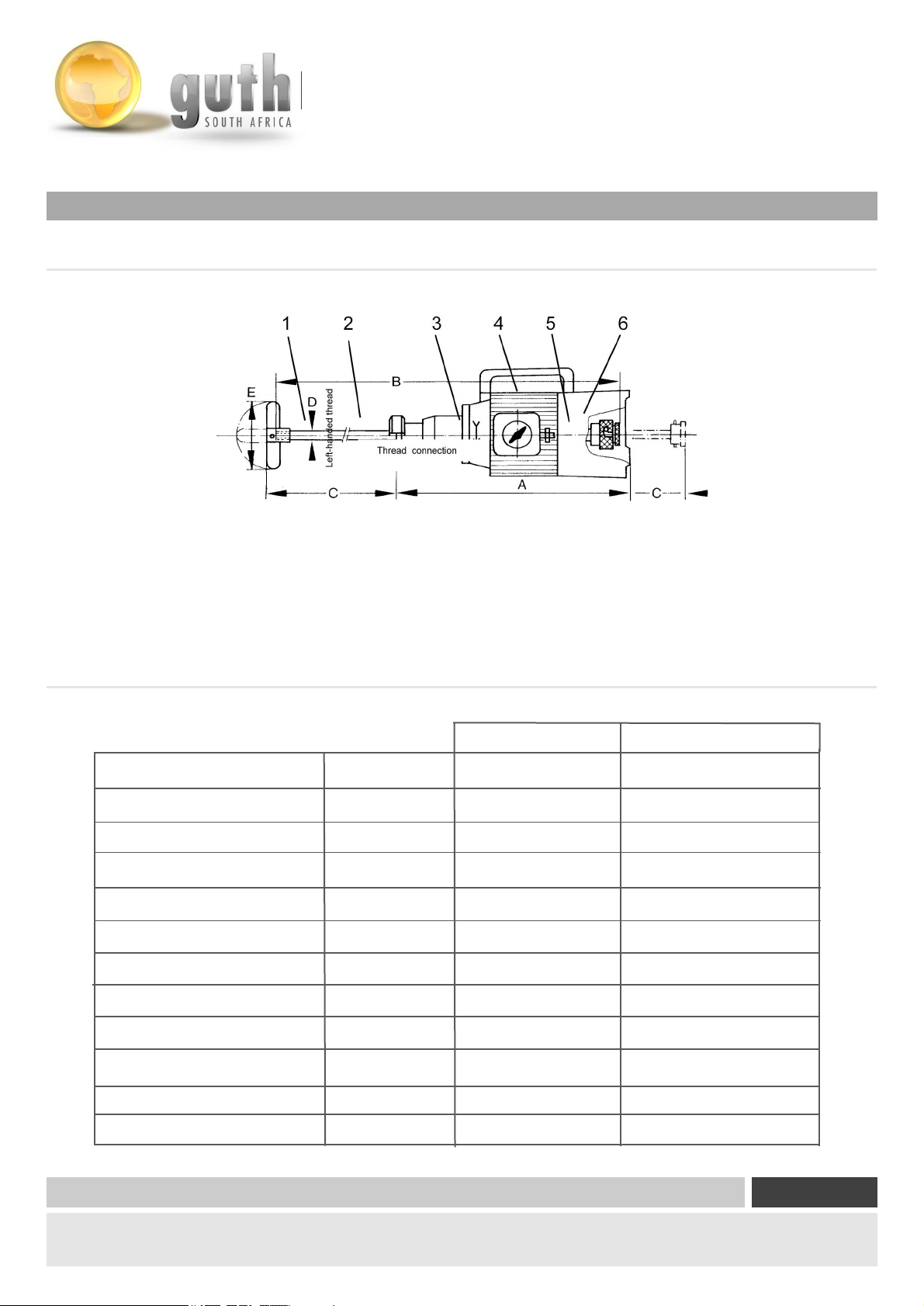
Fig. 1-1 Overview
1. Pr
opeller 4. Hollow shaft motor
2. Mixer shaft 5. Hollow shaft coupling
3. Floating ring seal 6. Mixer shaft coupling
1.3 Technical specifications{XE "Technical specifications"}
Tank volume
Power
Voltage
Frequency
Speed
Nominal current
Weight
kW
V
Hz
rpm
A
kg
RA 45 RA 45
20000 L 20000 L
0.45 0.45
230 400
50 50
1500 1500
2.3 1.3
16 16
Length
Propeller E
© Copyright Page
Distribution and reproduction of this document, commercialisation and publication of its content is strictly forbidden. Contravention
is liable to payment of damages. All rights reserved.
A
B
C
D
410 410
800 800
425 425
28 28
147x25 17x25
|
03
Page 6

Flow Components
Capital Equipment
Engineered Processing Units
Product specifications
Viscosity: >20 Baumé = 36.34 Brix =
(equivalent to a 36% sugar solution at 20°
C) 1.2° Engler = 4 centipoise
Temperature range for{XE "Temperature range"}:
Mixer: -20°C to +180°C
product-dependent
Ambient conditions
Noise level: < 70 dtB (A)
Cleaning
The mixer is to be cleaned with water, dish-washing liquid and a soft cloth.
Do not use sharp objects or tools to clean the mixer.
© Copyright Page
Distribution and reproduction of this document, commercialisation and publication of its content is strictly forbidden. Contravention
is liable to payment of damages. All rights reserved.
|
03
Page 7
3. Safety
3.1 Notes/Explanations Explanations
Flow Components
Capital Equipment
Engineered Processing Units
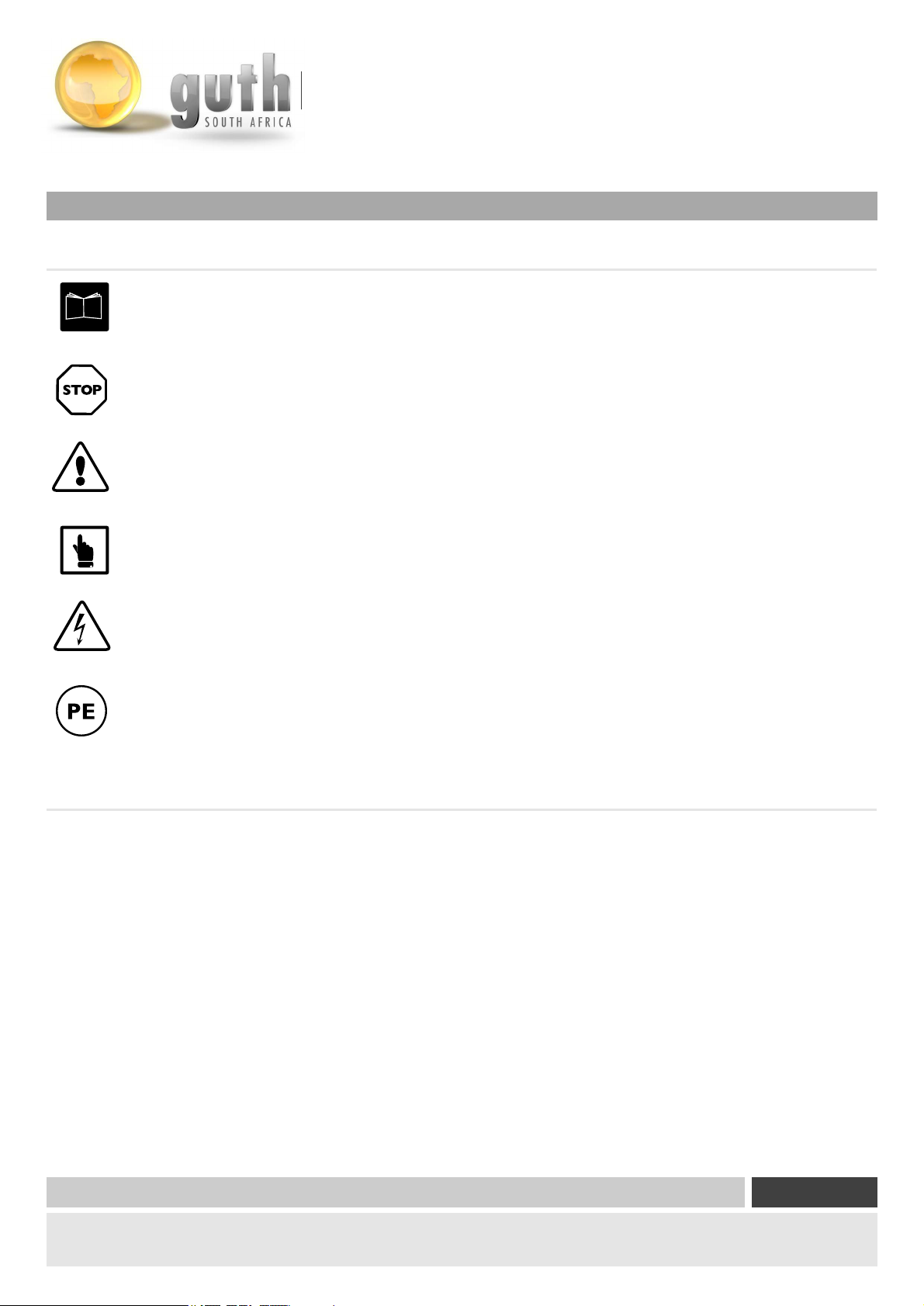
Operating manual mandator
y
framed and marked with a book symbol.
Warnings
framed and marked with a stop sign.
Dangers
framed and marked with a warning triangle.
Notes
framed and marked with a hand symbol.
Danger of electric shock
framed and marked with the symbol shown.
Protective conductor connection
marked at the connection points by the symbol shown.
Model number
The information in this operating manual only applies to the mixer
whose model number is specified on the title page.
A nameplate with the model number is attached to the protective
cover of the gear.
© Copyright Page
Distribution and reproduction of this document, commercialisation and publication of its content is strictly forbidden. Contravention
is liable to payment of damages. All rights reserved.
|
03
Page 8

3.2 Safety Standards
Flow Components
Capital Equipment
Engineered Processing Units
The mixer was built in conf
ormity with the following Germancodes
1. EC directives on machinery (89/392/EEC, 91/368/EEC,
93/44/EEC, 93/68/EEC)
1.1 DIN EN 00292-1: 11/91 Safety of machinery; principles
1.2 DIN EN 00292-2: 06/95 Safety of machinery; principles
1.3 DIN EN 00294: 08/92 Safety of machinery; safety distances
to keep the upper extremities from points of danger
1.4 DIN EN 00614-1: 04/95 Safety of machinery; ergonomic
design principles
1.5 DIN EN 01037: 04/96 Safety of machinery; prevention of
unexpected starts
1.6 DIN EN 60034-9: 05/96 Rotating electrical machinery; part 9:
noise limits
1.7 DIN EN 60034-9 A1: 08/96 Rotating electrical machinery; part
9: noise limits, amendment A1
1.8 DIN EN 60204-1: 06/93 Safety of machinery; electrical
equipment of machinery; part 1: general requirements
2. DIN EN 61000-4-2: 03/96 Electromagnetic compatibility
(EMC); testing and measuring methods
3. Equipment safety law machinery ordinance
- 3 GSGV / 9 GSGV
4. VDE 530 - Rotating electrical machinery
© Copyright Page
Distribution and reproduction of this document, commercialisation and publication of its content is strictly forbidden. Contravention
is liable to payment of damages. All rights reserved.
|
03
Page 9

Flow Components
Capital Equipment
Engineered Processing Units
3.3 Built-in safety systems {XE "Safety systems"}
- The mixer is equipped with a one or thr
ee-phase, three or fivewire supply system with current-carrying N and
separate earth conductor (with yellow/green insulation).
This operating manual is an integral part of the mixer and must be kept readily at hand for the
operators at all times.
The safety instructions in it must be followed.
Also pay attention to the protective motor switch built into the motor as safety system;
see separate operating manual.
It is strictly forbidden to render any of the safety devices inoperative.
3.4 Safety precautions{XE "Safety precautions"} (to be carried out by the customer)
The customer must
- instruct his operating and maintenance personnel in the use of the mixer and its safety devices and
- ensure that the safety precautions are being adhered to. This operating manual is an integral part of the
mixer and must be kept readily at hand for the operators at all times.
The work described in this operating manual is explained in such a way that
- the chapters Transport, Operation and Installation can be
understood by a trained worker and
- the chapters Maintenance and Troubleshooting by a qualified technician.
Work described in the chapters Maintenance and Troubleshooting may only be carried out
by qualified technicians.
Definitions based on EN 60204-1.
Trained worker {XE "Trained worker"}
- A person familiarized with and, if applicable, trained in his particular duties by a qualified technician and instructed
in the potential dangers in the event of improper conduct and in the necessary safety devices and safety precautions.
Qualified technician{XE "Qualified technician"}
- A person who, on account of his technical training, know-how, experience and knowledge of relevant standards, is
able to assess the work assigned to him and identify potential dangers.
© Copyright Page
Distribution and reproduction of this document, commercialisation and publication of its content is strictly forbidden. Contravention
is liable to payment of damages. All rights reserved.
|
03
Page 10

2.5 Responsibilities of the customer
Flow Components
Capital Equipment
Engineered Processing Units
In the EEA (European Economic
Area) national implementation of the framework directive 89/391/EEC and
corresponding individual directives, in particular the directive (89/655/EEC) on the minimum regulations for
safety and health protection in the use of work materials and tools by employees at work, as amended, are
to be observed and adhered to.
The customer must observe local laws and regulations on:
- personnel safety (accident prevention regulations)
- safety of work materials and tools (safety equipment and
maintenance)
- disposal of products (laws on wastes)
- disposal of materials (laws on wastes)
- cleaning (cleaning agents and disposal)
- environmental protection
The customer must observe any local regulations on, for example, the connection of electric power supplies when installing
and commissioning the mixer himself.
© Copyright Page
Distribution and reproduction of this document, commercialisation and publication of its content is strictly forbidden. Contravention
is liable to payment of damages. All rights reserved.
|
03
Page 11

3.6 Safety inspections and tests
Flow Components
Capital Equipment
Engineered Processing Units
Factory inspections and tests b
y the manufacturer
1. Airborne noise measurement
- According to the machinery directive, appendix 1(Point 1.7.4/ff.)
2. Safety tests in terms of DIN EN 60 204 - 1
- Continuous connection of the protective conductor system
(Chapter 20.2)
- Insulation resistance tests (Chapter 20.3)
- Voltage tests (Chapter 20.4)
- Protection against residual voltage (Chapter 20.5)
- Testing of electromagnetic compatibility in accordance with
EMC directives
- Function tests (Chapter 20.7)
Functions of electrical equipment, particularly those
concerning safety and protective measure
3.7 General warnings
The electric power supply cable must be routed so that there is no danger of anybody tripping
over it!
Only mount and dismount the mixer when the mains plug has been pulled out of its socket.
Make sure the tank fittings are mounted to the full tank correctly when inserting the mixer.
Close the tank fitting before dismounting the mixer.
When inserting or removing the mixer make sure any liquid product discharging during this
work is caught or drained off. Also pay attention to the warnings in the attached operating
manual on the motor.
Avoid driving over the electric power supply cable. Make sure the electric power supply cable
cannot be pinched anywhere. If you have a three-phase motor version of the mixer, make sure
the phase sequence is clockwise; if not, have an electrician interchange two phases of the power
supply cable.
© Copyright Page
Distribution and reproduction of this document, commercialisation and publication of its content is strictly forbidden. Contravention
is liable to payment of damages. All rights reserved.
|
03
Page 12

3.8 Spare and wearing parts
Flow Components
Capital Equipment
Engineered Processing Units
Spare par
ts and accessories that have not been supplied by us have also not been tested and approved by us. The fitting
and/or use of such products could therefore negatively affect the design
characteristics of your mixer.
WILHELM GUTH GmbH accepts no liability for damages arising from the use of non-original parts and accessories.
Standard parts can be bought through the specialized trade.
The spare parts list is attached in the appendix to this operating manual.
3.9 Shutdown procedure
The following shutdown procedure must be followed before any cleaning, maintenance or repair work
is carried out:
Switch off the mixer
- Switch off the on/off switch.
- Pull out the mains plug.
Shut off the product supply
- Close the tank fitting.
Dismount the mixer
There is a danger to life and limb of the personnel if this procedure is not followed!
© Copyright Page
|
03
Distribution and reproduction of this document, commercialisation and publication of its content is strictly forbidden. Contravention
is liable to payment of damages. All rights reserved.
Page 13

4. Installation
4.1 Scope of delivery
Flow Components
Capital Equipment
Engineered Processing Units
The scope of deliver
y comprises the mixer, a tank fitting and a propeller in accordance with our acknowledgement of
your order and the delivery note as well as this operating manual and technical reference material.
On request the hollow shaft motor can be designed for other voltages. The mixer is also available in an
explosion-proof version.
3.2 Transport and packing
The mixer is carefully inspected and packed before shipment. Nevertheless, it is still possible that it might become damaged
during transit.
Receiving inspection
- Check the shipment against the delivery note to ensure that it is complete!
If the packing is damaged
- Check the shipment itself for damage (visual inspection)!
Complaints
If the shipment was damaged during transit:
- Immediately contact the last carrier!
- Keep the packing material (in case the carrier wants to inspect it or the shipment has to be returned to us)!
Packing for return shipment
Use the original packing material as far as possible.
If it is no longer available:
- Use the services of a packing company with specializedpersonnel.
- Consult GUTH GmbH should you have any questions on the packing and protection of the mixer for shipment.
Sea-worthy packing
For overseas shipment the mixer is sealed in foil together with desiccant.
Storage in the open
The mixer may not be stored in the open. The desiccant sealed in foil together with the mixer for overseas shipment
suffices for a storage period of up to three months.
Storage in a closed room
Storage conditions
- Temperature 20°C to 30°C
- Humidity < 60%
Also pay attention to the chapters Receiving,Transport and Storage in the separate operating manual on
the motor.
© Copyright Page
Distribution and reproduction of this document, commercialisation and publication of its content is strictly forbidden. Contravention
is liable to payment of damages. All rights reserved.
|
03
Page 14
3.3 Mounting/Installation
Mounting information
Flow Components
Capital Equipment
Engineered Processing Units
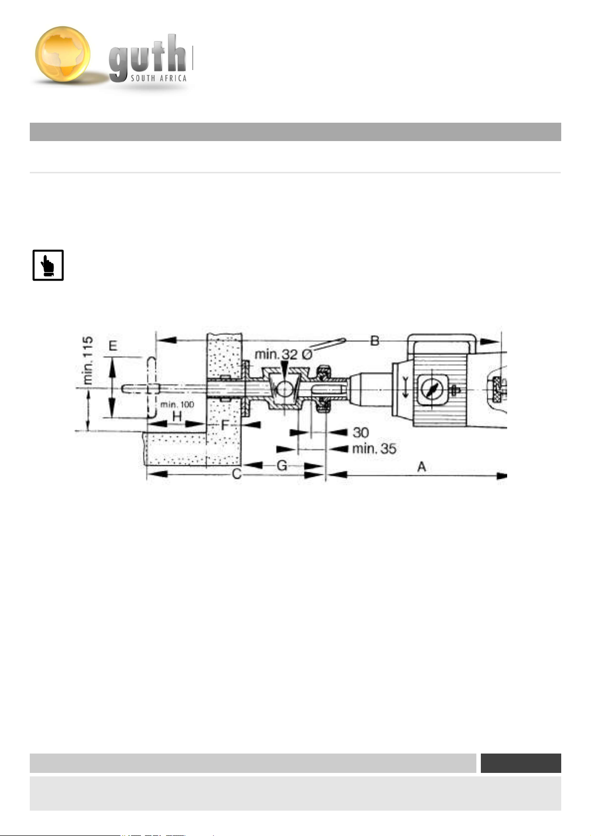
The length of the shaft H extending into the liquid in the tank is obtained b
y subtracting the face-to-face dimension G
of the connection fitting and the thickness F of the tank wall from the length C (H = C - G - F).
Specify the desired shaft length C in your order (C = G + F + H). Take the standard lengths B
of the individual models into account; they are available in lengths of up to max. 1200 mm.
Fig. 4-1 Fitting dimension
© Copyright Page
Distribution and reproduction of this document, commercialisation and publication of its content is strictly forbidden. Contravention
is liable to payment of damages. All rights reserved.
|
03
Page 15

3.4 Mounting the mixer shaft
Flow Components
Capital Equipment
Engineered Processing Units
For shipping r
easons the motor and mixer shaft are delivered dismounted.
Mount as follows: (see Fig. 1-1)
- Unscrew the propeller (1) from the mixer shaft (2). Note that the thread is left-handed!
- Insert the mixer shaft (2) into the opening of the hollow shaft (5) from the coupling side of the motor until the thread
of the mixer shaft is completely visible on the connection side of the motor.
- Screw the propeller (1) back on to the mixer shaft (2). Remember that the thread is left-handed!
- Pull the mixer shaft back as far as it goes. The mixer is ready for connection.
3.5 Checking the sense of rotation of the motor
The sense of rotation must be checked before the mixer is connected to the tank because the propeller will
come loose from the mixer shaft if it is wrong.
Check as follows:
- Connect the mixer to the power supply.
- Switch the on/off switch on to “I” briefly so that the motor turns a little (not continuously).
- Check whether the motor turns in the direction of the arrow on themotor.
- If it does not, have this corrected by a qualified technician.
- The propeller boss has wrench flats for unscrewing of the propeller. If the propeller is too tight, hold the mixer shaft
tight at the mixer shaft coupling.
When checking the sense of rotation make sure you do not hold or try to grip the shaft or propeller.
Danger of injury!
Do not hold the mixer shaft tight on the shaft itself because this can damage the mixer shaft and the seal (the
latter when pulling back the shaft).
A wrong sense of rotation will also damage the floating ring seal.
Also pay attention to the attached operating manual on the motor.
© Copyright Page
Distribution and reproduction of this document, commercialisation and publication of its content is strictly forbidden. Contravention
is liable to payment of damages. All rights reserved.
|
03
Page 16

Flow Components
Capital Equipment
Engineered Processing Units
5. Functional Description
All parts that come into contact with liquid are made of non-corroding steel (1.4301).
The mixer is connected to the full tank with the tank fitting:
-
Slanted seat valve
- Flow cock
- Drain valve
- Butterfly valve socket
- The retractable mixer shaft allows front mounting on the tank and insertion of the propeller into the medium without
any loss of liquid or pressure.
- The special bearing of the mixer shaft in the hollow shaft of the electric motor ensures a steady and
vibrationless run.
- The floating ring seal {XE "Floating ring seal"}NP 1-2 SR guarantees troublefree continuous duty up to 10 bar.
A special floating ring seal is needed when stirring corrosive products.
© Copyright Page
Distribution and reproduction of this document, commercialisation and publication of its content is strictly forbidden. Contravention
is liable to payment of damages. All rights reserved.
|
03
Page 17

6. Operation
6.1 Connection to the tank fitting
Flow Components
Capital Equipment
Engineered Processing Units
Connect as follo
ws:
- Check whether the tank fitting is closed; if not, close.
- Loosen and remove the seal cap of the fitting so that the thread of the fitting for connection of the mixer is accessible.
- Place the mixer with retracted mixer shaft on the thread, screw on the companion nut and tighten with a
sickle spanner.
- Open the tank fitting. The connected mixer seals off.
- Push the mixer shaft through the hollow shaft completely to the connection side of the motor.
- Hold the hollow shaft coupling (5) tight with your left hand.
- Turn the mixer shaft coupling (6) clockwise with your right hand until the coupling pin catches in the indent.
- Plug the mains plug into the socket.
- Switch on the mixer by switching the on/off switch on to “I”.
6.2 Disconnecting the tank fitting
Disconnect the tank fitting as follows: (see Fig. 1-1)
- Switch off the mixer by switching the on/off switch on to “0”.
- Pull out the mains plug.
- Hold the hollow shaft coupling (5) tight with your left hand.
- Turn the mixer shaft coupling (6) anti-clockwise with your right hand and remove the coupling pin from the indent.
- Pull the mixer shaft (2) through the hollow shaft completely to the coupling side of the motor as far as it goes.
- Close the tank fitting.
- Unscrew the companion nut with a sickle spanner and remove the mixer.
When inserting or removing the mixer make sure any liquid product discharging during this
work is caught or drained off.
© Copyright Page
Distribution and reproduction of this document, commercialisation and publication of its content is strictly forbidden. Contravention
is liable to payment of damages. All rights reserved.
|
03
Page 18

Flow Components
Capital Equipment
Engineered Processing Units
7. Cleaning
The following shutdown procedure must be followed before any cleaning, maintenance or
repair w
ork is carried out:
Switch off the mixer
- Switch off the on/off switch.
- Pull out the mains plug.
Shut off the product supply
- Close the tank fitting.
Dismount the mixer
There is a danger to life and limb of the
personnel if this procedure is not followed!
7.1 Daily cleaning
Clean only with water during the individual work intervals. Do not use a cleaning agent, because thorough rinsing
is then necessary
© Copyright Page
Distribution and reproduction of this document, commercialisation and publication of its content is strictly forbidden. Contravention
is liable to payment of damages. All rights reserved.
|
03
Page 19

Flow Components
Capital Equipment
Engineered Processing Units
6. Operation
6.2 General cleaning
General cleaning is to be carried out:
-
every six months
- when the tank is cleaned
- when the plant is shut down
The manufacturer accepts no liability for damage resulting from the use of cleaning agents or cleaning tools
other than those recommended or from improper handling!
No special cleaning agent is needed to clean stainless steel parts.
Use steam or alcohol for disinfection.
No cleaning agents containing
- soda lye, other high alkaline substances with chlorine, bromine, iodine or fluorine admixtures,
- potassium oxide,
- chlorous products,
- ammonium compounds, quaternaries,
- hydrochloric or hydrofluoric acid may be used because they corrode the stainless steel surface.
The flange housing with thread connection is to be removed and
cleaned once a year.
Pay attention
- to the instructions in the safety data sheets of the manufacturer's of the cleaning agents.
These instructions must be followed.
The onus of proof that the cleaning agents were used properly lies with the customer.
Use a coarse scrubbing or plastic brush to clean the stainless steel parts.
© Copyright Page
Distribution and reproduction of this document, commercialisation and publication of its content is strictly forbidden. Contravention
is liable to payment of damages. All rights reserved.
|
03
Page 20

8. Maintenance/Installation
The GUTH mixer may only be taken apart and serviced technically by qualified technicians.
Flow Components
Capital Equipment
Engineered Processing Units
Also pay attention to the cha
pter on maintenance of the motor in the separate
operating manual.
Qualified technician
- A person who, on account of his technical training, know-how, experience and knowledge of relevant
standards, is able to assess the work assigned to him and identify potential dangers.
Definition based on EN 60204-1.
The following shutdown procedure must be followed before any cleaning, maintenance or
repair work is carried out:
Switch off the mixer
- Switch off the on/off switch.
- Pull out the mains plug.
Shut off the product supply
- Close the tank fitting.
Dismount the mixer
There is a danger to life and limb of the
personnel if this procedure is not followed!
GUTH mixers are maintenance-free. They are, however, subject to normal wear and tear and must be
checked at regular intervals by a qualified technician in accordance with accident prevention regulations
(e.g. VBG 4 Electrical installations and apparatus).
© Copyright Page
Distribution and reproduction of this document, commercialisation and publication of its content is strictly forbidden. Contravention
is liable to payment of damages. All rights reserved.
|
03
Page 21

9. Troubleshooting
The situations and instructions on troubleshooting described in this chapter are explained in such a way that
they can be understood b
Maintenance work may only be carried out by a qualified technician.
The shutdown procedure (see Chap. 3.9) must be followed before any maintenance or repair work is
carried out.
If the measures described below do not prove successful, please contact WILHELM GUTH GmbH.
Flow Components
Capital Equipment
Engineered Processing Units
y a trained worker.
Fault Cause
Mixer does not work
Folding propeller
does not open
Mixer shaft vibrates
gly
stron
Liquid leaks from the
leak holes in t
flange housing (mixer
connection side)
he
Plug connections of
wer supply are
the po
loose
Blades deformed
Blades stuck
Folding propeller
does not open
Shaft ben
Motor shaft bearing
Floating ring or motor
shaft seal dama
t
ged
Correction
Check the mains
fasten if
plug,
necessary
Replace the folding
opeller
pr
Clean carefully
Clean carefully or
replace t
propeller
Replace the shaft,
check the folding
propeller
Send in the complete
mixer for repairs
Send in the complete
mixer f
renew replaceable
parts
he folding
or repairs or
Liquid leaks from the
shaft coupli
(coupling side)
© Copyright Page
Distribution and reproduction of this document, commercialisation and publication of its content is strictly forbidden. Contravention
is liable to payment of damages. All rights reserved.
ng
Replace mixer shafts that are no longer perfectly centred because they cause unbalanced shaft rotation. This
in turn wears out the motor shaft bearing and damages the floating ring and motor shaft seals. Depending on
the extent of the damage
Mixer shaft seal
ged
dama
, liquid is then able to penetrate into the motor, which can short circuit.
Send in the complete
mixer f
renew replaceable
or repairs or
|
03
Page 22

Flow Components
Capital Equipment
Engineered Processing Units
10. Emergencies
In the event of an emergency
- sw
itch off the on/off switch and
- pull out the mains plug.
11. Dismounting/Disposal
The mixer is primarily made of steel (except for the electrical equipment) and is to be disposed of in accordance with
valid local en
vironmental protection laws.
Cleaning agents must be disposed of in accordance with local regulations and the manufacturer's instructions in the safety
data sheet.
© Copyright Page
Distribution and reproduction of this document, commercialisation and publication of its content is strictly forbidden. Contravention
is liable to payment of damages. All rights reserved.
|
03
Page 23
12. Apendix
Flow Components
Capital Equipment
Engineered Processing Units
A
C
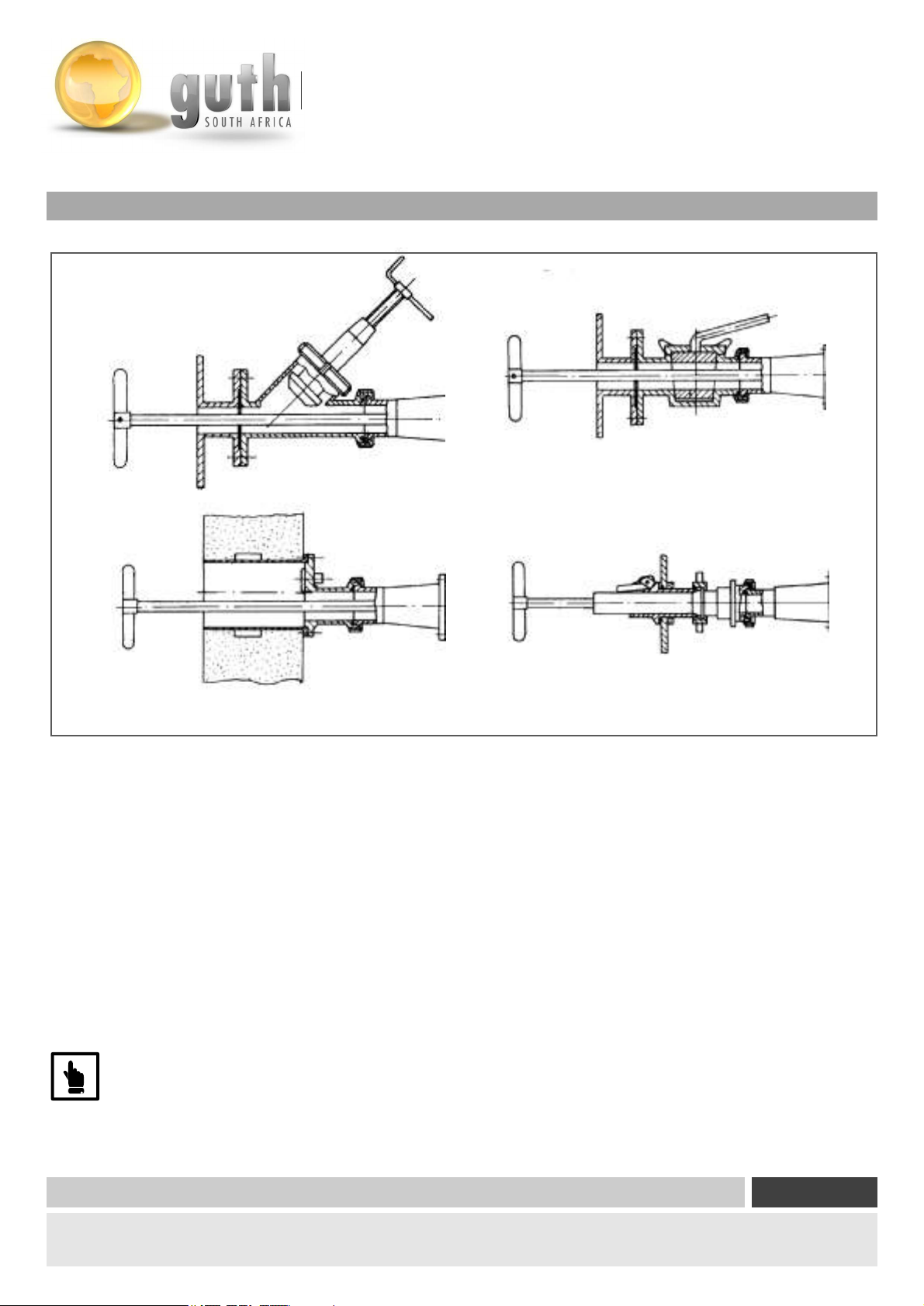
Fig. 1-1 Tank fittings
A Slanted seat valve
B
Flow cock
C Drain valve
D Butterfly valve socket with detachable pipe
Full opening of all tank fittings must be guaranteed. They are opened as follows:
- Slanted seat valve – by screwing out the valve spindle
- Flow cock – by turning the ball
- Drain valve – by turning away the cover plate
B
D
If a butterfly valve socket is needed, the detachable pipe must be used. Abutting of the butterfly valve can result in damage
to the floating ring seal.
The tank fitting must be designed for the particular model of mixer.
© Copyright Page
Distribution and reproduction of this document, commercialisation and publication of its content is strictly forbidden. Contravention
is liable to payment of damages. All rights reserved.
|
03
Page 24
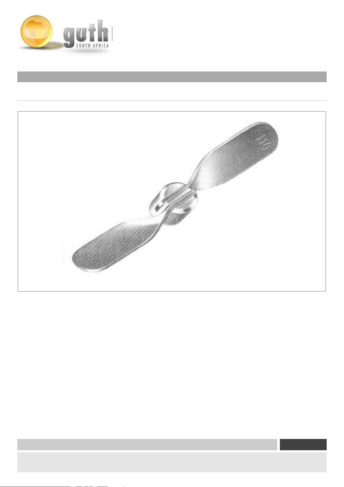
Folding Propellor
Flow Components
Capital Equipment
Engineered Processing Units
Fig. 2-1 Folding propeller
Folding pr
opeller serves insertion in tank fittings with small openings in folded state.
The folding propeller blade unfolds and folds automatically when the mixer is switched
on and off respectively.
© Copyright Page
Distribution and reproduction of this document, commercialisation and publication of its content is strictly forbidden. Contravention
is liable to payment of damages. All rights reserved.
|
03
Page 25
Flow Components
Capital Equipment
Engineered Processing Units
Optional Extra’s
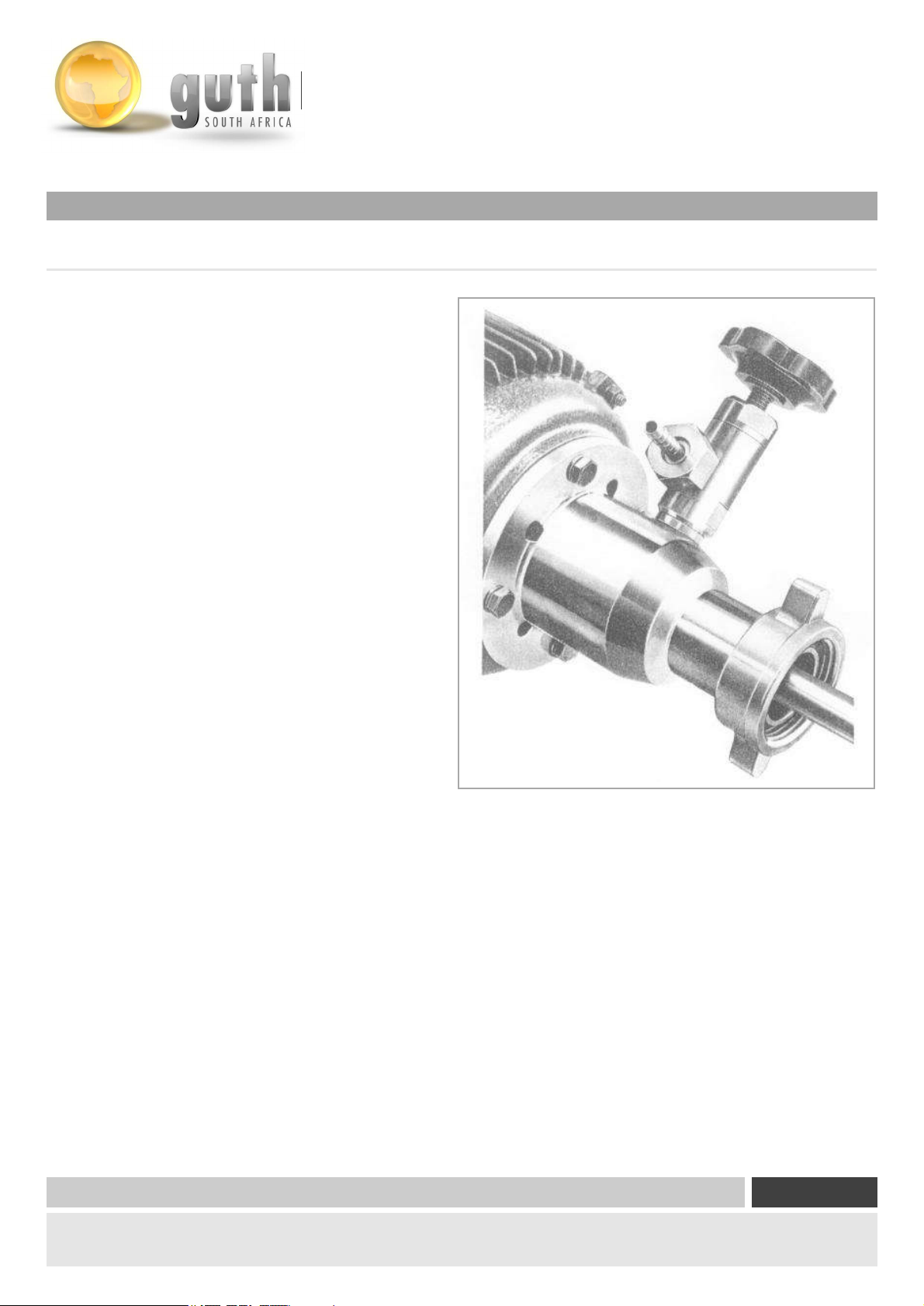
3.1 Gassing Device
The gassing device is made of chrome nickel steel
and enables direct gassing with sulphur dio
xide (SO2)
and carbon dioxide (CO2) with rotating mixer shaft.
The gases being added are mixed intensively
on admission.
Fig. 3-1 Gassing device
© Copyright Page
Distribution and reproduction of this document, commercialisation and publication of its content is strictly forbidden. Contravention
is liable to payment of damages. All rights reserved.
|
03
Page 26
Optional Extra’s
3.2 Mobile Stand
Flow Components
Capital Equipment
Engineered Processing Units
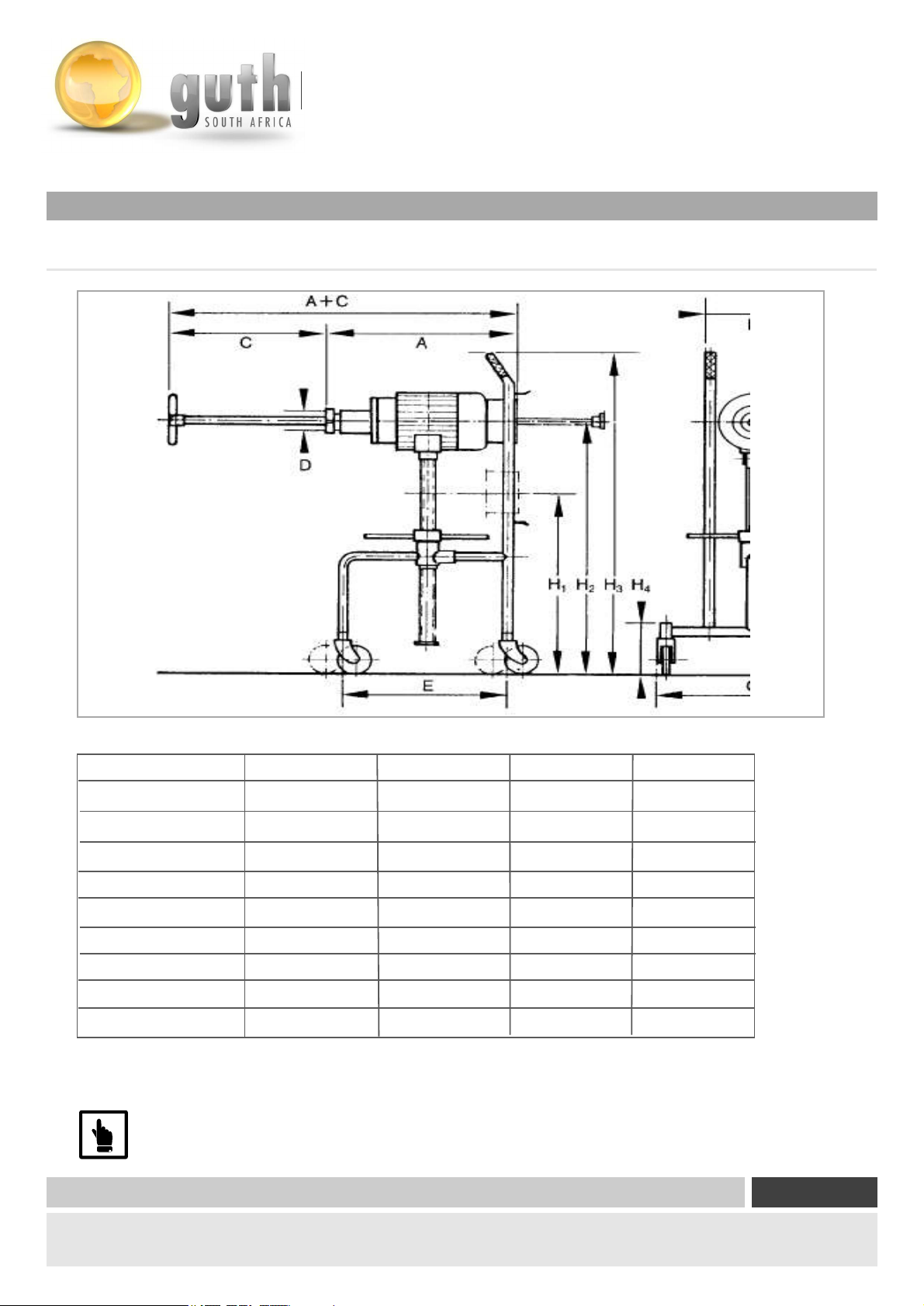
Fig. 3-2 Mobile stand
Size 0 Size 1 Size 2 Size
F
G
H1
H2
H3
H4
A
C
E
The mobile stand supports the operating mixer mounted on the tank fitting. Thanks to the better
handling possibilities it offers,
If the tank with tank fitting is not designed for the weight of the mixer, a mobile stand
must be used.
250 250 250 250
500 500 500 700
450 500 650 950
600 700 1000
1500 1060
1060 1060 1060
170 170 170 170
410 410 410 410
425 425 425 425
the stand greatly facilitates mounting and dismounting of the mixer.
© Copyright Page
Distribution and reproduction of this document, commercialisation and publication of its content is strictly forbidden. Contravention
is liable to payment of damages. All rights reserved.
|
03
Page 27
Optional Extra’s
3.2 Mobile Stand
Flow Components
Capital Equipment
Engineered Processing Units
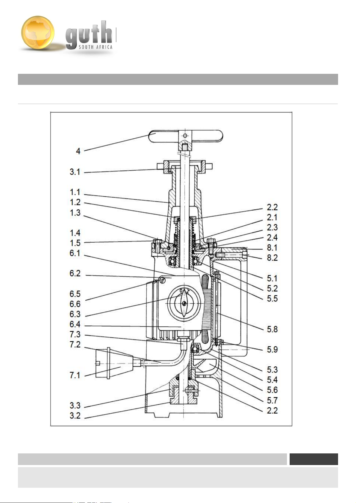
Fig. 4-1 Spare parts
© Copyright Page
Distribution and reproduction of this document, commercialisation and publication of its content is strictly forbidden. Contravention
is liable to payment of damages. All rights reserved.
|
03
Page 28

Contact Us
Johonnesburg:
79 St Georges Street,
PO Box 58070, Newville, 2114
Phone: + 27 (0)11 477-4923
Fax: + 27 (0)11 477-8062
e-mail: [email protected]
Newlands
Cape Town:
2 Platinum Rd,
PO Box 1486, Milnerton, 7435
Phone: + 27 (0)21 555-8300
Fax: + 27 (0)21 552-2228
e-mail: [email protected]
Port Elizabeth:
Unit 24,
PO Box 70496, The Bridge PO, Port Elizabeth, 6032
Phone: + 27 (0)41 367 2431
Fax: + 27 (0)41 367 5152
email: [email protected]
Willow Road Business Park, 33 Willow Road, Fairview
Pinetown:
Unit 3 Pastel Park, 50
PO Box 8, Pinetown, 3600
Phone: + 27 (0)31 709-5444
Fax: + 27 (0)31 709-8333
e-mail: [email protected]
Marconi Industria, Montague Gardens
Wareing Road
 Loading...