

Guspro BB-8416884 Operation & Maintenance Manual

GUSPRO INC.
CHATHAM, ONTARIO
CANADA
HEAT CLEANING OVENS
OPERATIONS & MAINTENANCE MANUAL
OVENS WITH E BURNERS
2017_E_TYPE-HL.doc 24-Oct-2017

MODEL NUMBER: ____________________
C-18004
BB-8416884
SERIAL #: _________________
MANUFACTURED BY GUSPRO INC.
566 RIVERVIEW DRIVE
CHATHAM, ONTARIO
N7M 5J6
CANADA
TELEPHONE: (519) 352-4550
FAX: (519) 352-7676
Website: www.guspro.com
Email: Guspro@guspro.com
2017_E_TYPE-HL.doc 24-Oct-2017

NOTICE
Both the main gas valve and the electric supply should be clearly marked or tagged.
INSTALLATION
This unit shall be installed in accordance with the National Fuel Gas Code ANSI Z223.1,
The National Gas Installation Code CAN/CGA B149.1 or the Propane Installation Code
CAN/CGA-B 149.2, as applicable.
If applicable, the vent line from the gas appliance pressure regulator shall be installed to
the outdoors in accordance with local codes or, in the absence of local codes, with the
National Fuel Gas Code, ANSI Z223.1, Natural gas Installation Code, CAN/CGA-B149.1,
or the Propane Installation Code, CAN/CGA-B149.2, as applicable.
The unit and its individual shut off valves must be disconnected from the gas supply piping
system during any pressure testing of that system at test pressures in excess of 1/2 PSI (3.45
Kpa).
The unit when installed shall be electrically connected and grounded in accordance with
local codes, or in the absence of local codes, with the National Electrical Code,
ANSI/NFPA70, or the Canadian Electrical Code, CSAC22.2, as applicable.
AFTER INSTALLATION
After installation, be sure to maintain adequate combustion and ventilation air. Do not
allow materials or articles to be stacked or piled near or against the oven or burners so as
to block or inhibit air flow. In the case of a through the wall installation, do not allow snow
or ice to build up around the burner covers or the oven relief lid.
NOTICE
The oven manual should be retained for future use. A “C” sized electrical diagram is
contained in the manual. An electrical diagram is placed in the electrical panel.
• The Process Chamber referred to in this manual is also known as the Primary
Chamber.
• The Oxidizer Chamber referred to in this manual is also known as the Afterburner
or Secondary Chamber.
It is recommended that the operator reads Sections 4.2-4.4 prior to powering up the unit!!
2017_E_TYPE-HL.doc 24-Oct-2017

NOTICE - The purchaser shall post in a prominent locat ion, instructions to
be followed in the event the use r smells gas.
1) Turn OFF the main fuel supply valve. This will lockout the burners.
2) If the oven is in use, do not shut the electrical power off. This will allow the OTS to
function and prevent any runaway situations.
3) Ventilate area by opening windows and doors (if possible).
4) Contact your local supplier or licensed installer.
5) Notify Guspro Inc.
FOR YOUR SAFETY
Do not store or use gasoline or other flammable
vapours or liquids in the vicinity of this or any
other appliance.
WARNING: Improper installation, adjustment,
alterations, service or maintenance can cause
property damage, injury or death. Read the
installation, operating and maintenance
instructions thoroughly before installing or
servicing this equipment.
2017_E_TYPE-HL.doc 24-Oct-2017

TABLE OF CONTENTS
Page
1.0 - GUSPRO HEAT CLEANING OVEN .............................................................. 1
1.1 Introduction ....................................................................................................................1
1.2 Design ............................................................................................................................3
1.2.1 Introduction ..............................................................................................................3
1.2.2 Specifications ...........................................................................................................3
1.3 Burners ...........................................................................................................................5
1.4 Materials of Construction ..............................................................................................5
1.5 Instrumentation and Control ..........................................................................................5
1.6 Installation......................................................................................................................6
1.7 Air Permits .....................................................................................................................7
1.8 Local Codes ...................................................................................................................7
1.9 Safety Standards.............................................................................................................8
1.10 Warranty ........................................................................................................................8
2.0 - CONTROL AND SAFETY CONFIGURATION ............................................ 9
2.1 Introduction ....................................................................................................................9
2.2 Main Control Panel ........................................................................................................9
2.2.1 Temperature Controllers ........................................................................................11
2.2.2 Cycle Timer ...........................................................................................................11
2.2.3 Fault Light ..............................................................................................................11
2.2.4 Oxidizer or Process Chamber Faults......................................................................11
2.2.5 Reset Faults ............................................................................................................12
2.2.6 OTS Test ................................................................................................................12
2.2.7 Stack High Limit Controller [ETC-S]....................................................................12
2.3 Gas Burners ..................................................................................................................13
2.3.1 Technical Description ............................................................................................13
2.3.2 Process Chamber Burner Configuration ...............................................................14
2.3.3 Oxidizer Chamber Burner Configuration .............................................................14
2.4 Flame Safety Controls..................................................................................................15
2.5 Optional Controls .........................................................................................................15
2.6 Chart Recorder .............................................................................................................15
2.7 Core Temperature Controller .......................................................................................15
3.0 - INSTALLATION ............................................................................................ 16
3.1 Permits .........................................................................................................................16
3.2 Purchaser's Requirements Prior to Installation ............................................................16
3.3 Electrical Service .........................................................................................................17
3.3.1 Standard Ovens ......................................................................................................17
3.3.2 Ovens With Multi-Burner Chambers ....................................................................17
3.3.3 Ovens With Circulating Blowers ...........................................................................17
3.4 Fuel Supply ..................................................................................................................18
3.4.1 Natural Gas Service ...............................................................................................18
3.4.2 Liquefied Propane Gas Service .............................................................................19
3.4.3 Oil Service .............................................................................................................19
2017_E_TYPE-HL.doc 24-Oct-2017

3.5 Water Supply ...............................................................................................................19
3.6 Receiving .....................................................................................................................20
3.7 Storage .........................................................................................................................21
3.8 Installation....................................................................................................................21
3.8.1 Introduction ............................................................................................................21
3.8.2 Stack Installation ....................................................................................................21
3.8.3 Procedure ...............................................................................................................22
4.0 - OPERATION .................................................................................................. 25
4.1 Introduction ..................................................................................................................25
4.1.1 Process Chamber ....................................................................................................25
4.1.2 High Combustible Loads .......................................................................................25
4.1.3 Oxidizer Chamber ..................................................................................................26
4.2 System Checks Prior To Start-Up ...............................................................................26
4.3 Initial Start-Up .............................................................................................................27
4.4 Curing Procedure .........................................................................................................30
4.5 Operating Sequence .....................................................................................................31
4.6 Operating Procedure ....................................................................................................34
5.0 - PRECAUTIONS .............................................................................................. 36
5.1 Loading ........................................................................................................................36
5.2 Operation......................................................................................................................36
5.3 Parts..............................................................................................................................37
5.4 Emissions Control ........................................................................................................37
6.0 - GENERAL MAINTENANCE ........................................................................ 38
6.1 Introduction ..................................................................................................................38
6.2 Gas Burners ..................................................................................................................38
6.2.1 Electrode Assembly ...............................................................................................38
6.2.2 Electrode Gap.........................................................................................................38
6.2.3 U.V. Flame Scanner ...............................................................................................39
6.2.4 Blower ....................................................................................................................39
6.2.5 Blower Motor .........................................................................................................39
6.2.6 Air Flow Switch .....................................................................................................39
6.2.8 Automatic Gas Valve .............................................................................................40
6.2.9 Air Damper ............................................................................................................40
6.3 Door Gaskets and Seals ...............................................................................................40
6.5 Firebrick Soaps ............................................................................................................41
6.6 Lubrication of Loading Cart Wheels ...........................................................................41
6.7 Ash Handling and Disposal .........................................................................................42
6.8 Maintenance Tips .........................................................................................................42
7.0 - OVER TEMPERATURE SUPPRESSION SYSTEM .................................... 44
7.1 Introduction ..................................................................................................................44
7.2 Operation......................................................................................................................44
7.3 Testing..........................................................................................................................45
7.4 Instrument Synchronization .........................................................................................45
2017_E_TYPE-HL.doc 24-Oct-2017

7.5 Adjustments .................................................................................................................46
7.5.1 For Normal Loads ..................................................................................................46
8.0 - GENERAL TROUBLE-SHOOTING ............................................................. 46
8.1 Oven Will Not Start .....................................................................................................46
8.2 Electrical System Check ..............................................................................................47
8.3 Start Oven ....................................................................................................................47
8.4 Process Burner Fails To Purge .....................................................................................47
8.5 Oxidizer Burner Motor Fails To Start ..........................................................................48
8.6 Oxidizer Burner Motor Starts But Flame Does Not Ignite ..........................................48
8.7 Electrode Arcs But Pilot Does Not Ignite ....................................................................48
8.8 Pilot Fires But Will Not Stay Lit .................................................................................49
8.9 Pilot Lights But Main Burner Will Not Fire ................................................................49
8.10 Process Burner Motor Runs But The Flame Does Not Ignite .....................................49
8.11 Burner Cycles...............................................................................................................50
9.0 - E-BURNER ..................................................................................................... 50
9.1 Introduction ..................................................................................................................50
9.2 Design ..........................................................................................................................50
9.3 Ignition Sequence.........................................................................................................51
9.4 Maintenance .................................................................................................................51
9.5 Adjustments .................................................................................................................51
9.6 Trouble Shooting .........................................................................................................51
Appendix
Start-up Settings for Omron Temperature Controllers
Omron Temperature Controller Setup
Changing Set Point on Stack High Temperature Safety Controller
Omron Programmable Controller
Manufacturers Liter atu re
Valve Train
Wiring Ladder Diagram
2017_E_TYPE-HL.doc 24-Oct-2017

LIST OF TABLES
Table Page
1.1 Summary of Loads That Can Be Processed ..............................................................2
1.2 Summary of Loads That Cannot Be Processed .........................................................3
1.3 Oven Design Information ..........................................................................................4
1.4 Summary of Oxidizer Combustible Ratings ..............................................................4
3.1 Minimum Suggested Stack Clearances ...................................................................16
4.1 Firing Sequence .......................................................................................................33
6.1 Summary of Maintenance Tips ................................................................................44
9.1 E-Burner Factory Air and Gas Flow Settings ..........................................................55
9.2 E-Burner Trouble Shooting Tips .............................................................................55
LIST OF FIGURES
Figure Page
2.1 Main Control Panel with Electric Door Lock Option ..............................................10
3.1 Assembly Instructions for Bolt-On Oxidizers .........................................................23
3.2 Stack Assembly for Ovens With Heavy Duty Oxidizers .........................................24
4.1 Placement of Fire-brick Soaps .................................................................................30
9.1 Schematic of E-Burner ............................................................................................53
9.2 E-Burner Sequence of Operation .............................................................................54
2017_E_TYPE-HL.doc 24-Oct-2017

1.0 - GUSPRO HEAT CLEANING OVEN
1.1 Introduction
The Guspro heat-cleaning oven is state-of-the-art technology that enables heat cleaning
of parts coated with grease, oil, paint, carbon, plastics and water scale. Materials that can be heat
cleaned include steel, aluminum, and cast iron.
Applications include:
• Paint or powder coating line fixtures such as hooks, trees, trays and baskets.
• Paint, grease and combustion contaminated automotive engine blocks, heads, cranks,
camshafts, brake parts, transmissions, power boosters and water pumps.
• Epoxy and varnish coated components such as electrical motor armatures, stators and
transformer cores.
• Reclamation of manufactured parts with reject or service damaged coatings.
• Precious metal recovery in photographic film processing, transistors, printed circuit
boards and personal computer board salvage.
• Polymer coated tooling screws, breaker plates, dies and screens.
Parts are protected from distortion by precise temperature controls and backup control and safety
systems. Further, the heat cleaning process has the following advantages:
• Controlled heat cleaning cycles coupled with an absence of direct flame on the parts
prevents distortion and warpage.
• Operations are improved with safe, fast and efficient cleaning.
• Automatic operation ensures minimal operator supervision.
• Automatic over-temperature suppression system automatically injects water mist in case
of a sudden temperature rise, ensuring that high tolerance steel parts, and even most
aluminum parts are safely heat cleaned.
• The typical cycle time is 1.5 - 4.0 hours. Short cleaning cycles limit the exposure time of
parts to temperature, cut down fuel cost and provide fast turn around.
• Models are designed for at least two or three heat cleaning cycles per day, which is the
key to high efficiency and productivity.
• A platform cart is supplied. This ensures both a fast manual or optional lift truck loading
operation.
2017_E_TYPE-HL.doc Page 1 of 55 24-Oct-2017
Parts made of:
• Aluminum
• Iron
• Straight chain hydrocarbons (glues, adhesives, polymers).
• Low labour cost associated with automatic operation plus low fuel usage per cycle
ensures significant annual savings.
• Eliminates use of expensive cleaning chemicals, waste slurry disposal costs and
associated liability.
The burners on the Guspro heat cleaning ovens are sized to ensure that heavy loads are
brought to processing temperature fast. Depending on the oven model and site-specific loads,
the powerful standard refractory-lined oxidizer can process up to 70 pounds of combustibles per
hour once operating temperatures are reached. This amount may vary depending on the BTU
value of the combustible product being processed.
Note: The combustible load and cycle times are limited to the capacity of a given model’s
thermal oxidizer capacity. Extra heavy-duty or 100 pound afterburners are also
available as an option.
Heat passes from underneath the cart rack to heat the parts. This enhances temperature
uniformity in the process chamber while reducing energy consumption and cycle times.
The dry dust generated by the heat cleaning process meets stringent EPA solid waste
disposal standards (RCRA/SARA) and is easy to dispose of. A simple ash analysis on the dust
residue will determine if the dust requires special handling.
Tables 1.1 and 1.2 offer a summary of the type of automotive or industrial parts that can
and cannot be processed in the Oven.
Table 1.1
Summary of Loads that CAN be processed in the Oven
Note: It may be necessary to use slower heat up and cool down rates on some
parts to prevent thermal distortion.
• Steel
Coatings made of:
• Epoxy, polyester, powder and wet paints and coatings.
2017_E_TYPE-HL.doc Page 2 of 55 24-Oct-2017
• Magnesium which burns violently when ignited
Chlorinated compounds (PVC’s) - (Depends on concentration)
Fluorinated compounds (Teflon)
Table 1.2
Summary of Loads that CAN NOT be processed in the Oven
Parts Made of:
• Metals that melt under 900 oF (e.g. Zinc and its alloys)
• Alloy aluminum with a low melting point.
Coatings Made of:
Note: Guspro Inc. should be consulted before processing loads
1.2 Design
1.2.1 Introduction
Guspro heat cleaning ovens are of the two stage controlled air design. The first stage is
called the Process Chamber, while the second stage is called the Oxidizer Chamber.
A separate burner(s) heats each chamber. The process chamber burner(s) is fires into an
internal or external firebox. The oxidizer burner(s) fire directly into a chamber located on top of
the oven. A temperature control system oversees the operation of both burners. Flue gases are
vented to the atmosphere by a self-supporting refractory lined stack.
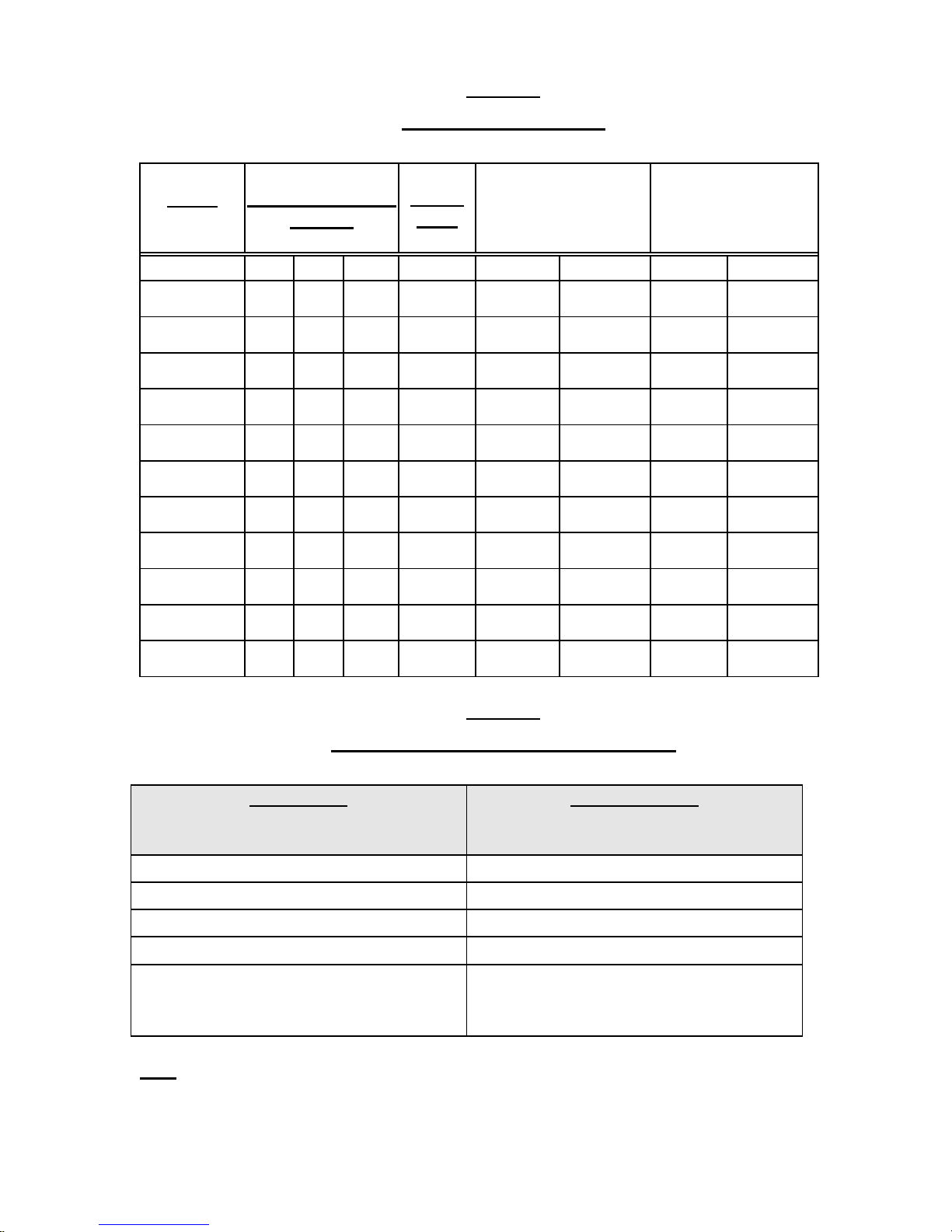
1.2.2 Specifications
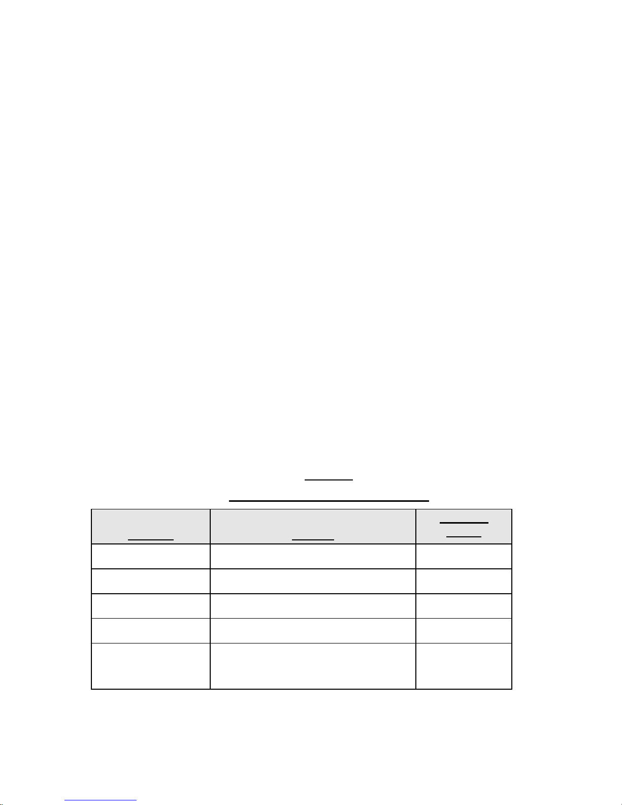
Table 1.3 lists the usable dimensions, burner models and ratings on standard Guspro
ovens. Guspro heat cleaning ovens are designed with larger oxidizer capacities to quickly and
efficiently burn off volatile particles from the process chamber, while complying with
environmental regulations. A summary of Oxidizer combustible ratings for standard Guspro
oven models is listed in Table 1.4.
2017_E_TYPE-HL.doc Page 3 of 55 24-Oct-2017
Actual Inside Dim.
W D H
LBS
PROCESS
OXIDIZER
PROCESS
OXIDIZER
GO-484072
54
48
99
3,000
500,000
750,000
E3
E4
GO-484084
54
48
111
3,000
500,000
750,000
E3
E4
GO-606060
66
68
87
4,000
750,000
750,000
E4
E4
GO-607272
66
80
99
4,000
750,000
750,000
E4
E4
GO-607284
66
80
111
4,000
750,000
750,000
E4
E4
GO-727272
78
80
99
5,000
1,000,000
1,000,000
E5
E5
GO-727284
78
80
111
5,000
1,000,000
1,000,000
E5
E5
GO-729672
78
104
99
6,000
1,000,000
1,000,000
E5
E5
GO-7212072
78
128
99
6,000
1,000,000
1,000,000
E5
E5
GO-7212096
78
128
123
6,000
1,000,000
1,000,000
E5
E5
GO-9612096
102
128
123
6,000
1,000,000
1,000,000
E5
E5
Oven Model
Oxidizer Rating
GO-484072 to GO-484084
40
GO-606060 to GO-607284
50
GO-727272 to GO-7212096
55
GO-9612096
70
Special models and standard models (GO-
100
Table 1.3
Oven Design Information
Model
(Inches)
Design
Load
Burner Rating
(BTU/hr)
Burner Model
Table 1.4
Summary of Oxidizer Combustible Ratings
(lbs/hr)
484072 and up) are available with larger
capacity oxidizers.
Note: Certain site specific applications may need special custom designed ovens or larger
capacity oxidizer chambers.
2017_E_TYPE-HL.doc Page 4 of 55 24-Oct-2017

1.3 Burners
Gas burners are equipped with approved ignition and flame safety systems. The burners
may be used with Liquefied Propane Gas (LPG) by a modification to the orifice. Fuel oil fired
ovens are available upon request.
1.4 Materials of Construction
All Guspro ovens are fabricated with hot rolled 7-gauge steel floors and 12-gauge steel
wall and roof backed by a framework of 3" channel, tube and flat iron. All steel work is finished
with two coats of 400 oF heat resistant paint on the outside, while the insides of the steel walls
are coated with chemical resistant Mastic.
The inside of oven walls and doors are insulated with three layers of insulation. The
innermost layer consists of 2" mineral fiber rock board, which is rated at 1200 oF. The next two
layers are made of 1/2" ceramic fiber board, which is rated at 2300 oF.
The wall insulation is anchored to the steel skin with stainless steel pins and clips.
The process chamber doors are equipped with a high temperature ceramic tadpole gasket,
hinges and cam type safety locking latches.
The floors are poured with 3" thick castable refractory. Cart tracks are embedded in the
refractory floor. Removable external cart track extensions are included.
Note: The cart track extensions may be left in place at all times. They do not have to be
removed to close the oven door.
The self-supporting stack is fully lined with a 2300 oF castable refractory. It is designed
to provide natural draft operation, and does not require either an exhaust blower or induced draft
fan.
1.5 Instrumentation and Control
A microprocessor - controlled operating system coordinates the functions of the process
burner, the oxidizer, and the Over Temperature Suppression (OTS) System during a heat
cleaning cycle. After the heat cleaning cycle, the system shuts down to cool.
All oven models have an OTS system included. The ovens come with a separate process
chamber excess temperature backup sensor. This will activate the OTS system by water mist
2017_E_TYPE-HL.doc Page 5 of 55 24-Oct-2017

injection in case the oven operational temperatures exceed set parameters.
The process burner is controlled by a programmable digital temperature controller, which
can store up to four programs patterns with 16 steps of ramp and soaks. The process burner uses
of a High/Low gas valve which will cycle between high and low fire to maintain set point. This
enables heat cleaning temperature control and fuel efficiency.
An independent digital temperature controller controls the oxidizer system. The oxidizer
temperature controller senses the stack temperature and controls oxidizer temperatures through
the use of a High/Low gas valve control system.
The use of a High/Low gas valve allows for a fast response oxidizer system (FRS). This
system gets the oxidizer to set point temperature quickly and then cycles to low fire to maintain
set point.
The oxidizer chamber also includes an excess airport for excess air combustion of
combustibles. The oxidizer chamber is designed to operate at a set-point temperature of between
1400 oF (760 0C) to 1600 oF (870 0C).
Note: The oxidizer set-point temperature is dependent on regulations set forth by the local air
pollution control authority. This value typically varies between 1400 oF and 1600 oF
over North America.
The oxidizer chamber is designed for a total residence time of 0.50 to 1.00 second
through the refractory lined mixing chamber and stack volume up to the thermocouple port.
Guspro ovens are equipped with a manual reset Excess Temperature Controller (ETC-S)
located in the panel. The ETC-S is used for safety shutdown if the flue gas temperature exceeds
a pre-set limit (1850 oF).
Operating and safety controls required by most provinces, states and local codes are
standard equipment. Special requirements such as Factory Mutual (FM) standards and Industrial
Risk Insurers (IRI) standards are available at extra cost where required by the purchaser or the
insurance underwriter.
1.6 Installation
The Guspro heat-cleaning oven is completely piped, wired and tested at the factory to
reduce installation costs to a minimum.
2017_E_TYPE-HL.doc Page 6 of 55 24-Oct-2017

1.7 Air Permits
The Guspro heat-cleaning oven is state-of-the-art technology that enables safe and
economical cleaning of automotive and industrial parts, fixtures, paint hooks and racks.
However, operation of the oven will require an air permit from the local Air Pollution Control
Authority.
The process of securing a permit to construct or install process equipment like the Guspro
oven usually requires that the purchaser fill out the applicable local forms and provide
information about the process, the equipment and the location where the equipment is to be used.
Upon request, Guspro Inc. will furnish an appropriate Air Permit support package that
can be used as an application package for submittal to the local authorities. The package
generally requires completion of the Air Quality portions of local forms. Guspro Inc. will supply
supporting technical documentation such as:
• Expected stack emissions.
• Combustion gas flow rates.
• Operating temperatures.
• Heat and mass balances.
• Residence time calculations.
The purchaser must supply the following information:
• Local application forms.
• Owner of the equipment.
• Persons responsible.
• Physical locations (including plot plans where required)
• Any other information required
The purchaser is ultimately responsible for fully completing, signing and submitting the
completed forms along with any necessary filing fees.
1.8 Local Codes
The Guspro Heat Cleaning Oven is designed to comply with most building and safety
codes. If any modifications are requested for compliance with other codes or regulations,
Guspro Inc. will review the requirements. Guspro Inc will then provide a cost estimate for
additional work required to meet these standards.
2017_E_TYPE-HL.doc Page 7 of 55 24-Oct-2017

1.9 Safety Standards
OSHA standards have not yet been released for this class of equipment. The installed
flame safety systems have a 4.0 second proof of ignition and a 0.8 second flameout response
time.
The Guspro safety systems meet current industry standards. The comprehensive features
of the Guspro safety system also ensure compliance with potential future standards.
1.10 Warranty
Guspro Inc. guarantees its equipment against defects in materials and workmanship,
when operated in accordance with standard operating instructions. The warranty is good for a
period of one year from date of shipment.
During this time period, defective parts will be replaced free of charge. Parts subject to
normal deterioration in use, such as spark electrodes, electric relays, panel light bulbs, gaskets,
fire-box tiles, etc. are not covered by this warranty.
Guspro Inc. makes no guarantee with respect to motors, controls, or other apparatus of
third party manufacture. The respective manufacturers usually guarantee these separately.
Guspro Inc. handles warranty exchange of such parts on behalf of the customer.
Guspro Inc. cannot accept responsibility for damage or injury resulting from oven
operation.
When operated in accordance with manufacturer's instructions, all Guspro ovens are
guaranteed to comply with the EPA particulate emission standard of 11 mg/Rm3 (15 mg/dscm @
7% O2). Costs of source tests that may be required by local air pollution agencies are not
included in the base price of the unit.
2017_E_TYPE-HL.doc Page 8 of 55 24-Oct-2017

2.0 - CONTROL AND SAFETY CONFIGURATION
2.1 Introduction
Figure 2.1 displays a schematic of the main control panel.
2.2 Main Control Panel
The central control panel includes the following features:
• Two 1/8 DIN digital temperature controllers. One controller controls the burner(s) and
the temperature in the process chamber. The other controller controls the burner(s) and
the temperature in the oxidizer chamber via a High/Low fire - modulating actuator.
• A 1/16 DIN controller, which serves as an OTS High Temp controller.
• System-on and burner-on indicating lights.
• Relays and interconnects.
• ETC-S High Temperature. All ovens have a second 1/16 DIN digital temperature
controller. This Factory Mutual (FM) approved controller and is used for system lockout
if the temperature exceeds safety limits. This controller is also used in FM and Industrial
Risk Insurers (IRI) approved ovens.
A brief description of the functionality of each of these elements is presented in the
following sections.
2017_E_TYPE-HL.doc Page 9 of 55 24-Oct-2017
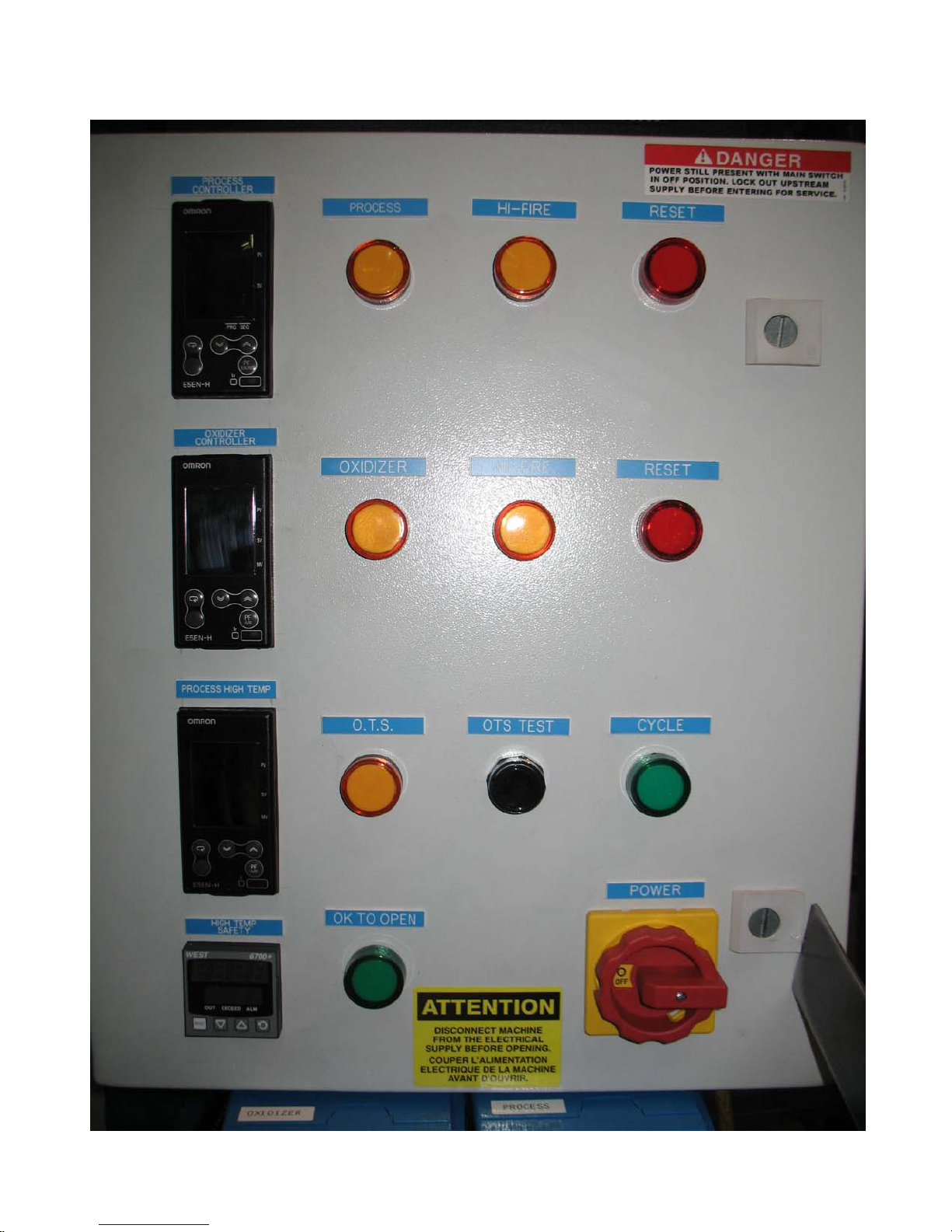
Figure 2.1 Main Control Panel with Electric Door Lock Option.
2017_E_TYPE-HL.doc Page 10 of 55 24-Oct-2017

2.2.1 Temperature Controllers
All ovens include digital temperature controllers actuated by a Type K thermocouple(s)
located in the process and oxidizer chambers. Instructions for setting up these controllers are
listed in the Appendix.
The controllers have an adjustable hysteresis for better control. This is set at the factory
and should not be adjusted unless Guspro has been consulted.
The oxidizer burner is fired automatically and remains on high fire until the
microprocessor set point is achieved. It will then cycle high/low fire to maintain the chamber
temperature. The process chamber burner does not fire until the oxidizer chamber reaches 1400
degrees Fahrenheit. The burner will then cycle high/low fire to maintain the process chamber
temperature.
Note: All ovens include an Over Temperature Suppression misting system in the process
chamber. The OTS system is activated by the process and oxidizer chamber
temperature controllers on the main panel.
2.2.2 Cycle Timer
All Guspro ovens are supplied with programmable ramp and soak microprocessor
controllers and may not have a separate cycle timer. The microprocessor controls the cycle time.
2.2.3 Fault Light
Red Fault lights located on the panel will indicate if either the process or oxidizer
chamber burners has faulted out and gone into Reset mode.
2.2.4 Oxidizer or Process Chamber Faults
If the oxidizer chamber faults out on start-up the process chamber burner will not ignite.
If the oxidizer chamber burner faults out during operation, the process chamber burner will shut
down. If the process chamber burner faults out, the oxidizer chamber burner will continue to
run. This ensures maximum environmental protection.
2017_E_TYPE-HL.doc Page 11 of 55 24-Oct-2017

2.2.5 Reset Faults
The Reset Faults push buttons are located on the flame safety modules. It is used to
resume normal operation after either a Process or Oxidizer fault has been corrected.
2.2.6 OTS Test
The OTS (Over Temperature Suppression) Test push-button is used to verify that the
OTS spray misting system is functioning properly. The OTS system is an integral and highly
important safety feature that ensures that a runaway combustion event that drives up either the
process chamber, the oxidizer chamber or the stack gas temperatures above acceptable limits
does not occur.
Before starting the processing cycle, the operator should open the process chamber doors
and push the OTS Test push-button. The operator should observe and ensure that the misting
nozzles are misting properly.
The OTS misting nozzle must mist to be effective. If the water is injected directly
without misting, it will not have any effect in suppressing over-temperature conditions in the
process chamber. This visual inspection will verify that the misting pin is not broken and that
the nozzles are not plugged. This inspection is very important and should be performed prior to
each start-up.
2.2.7 Stack High Limit Controller [ETC-S]
Some older model ovens include an Excess Temperature Control-System (ETC-S) switch
located in the stack base. If the temperature of the flue gas from the oxidizer chamber exceeds a
preset temperature, the ETC-S opens up the circuit to the system and shuts it down. However, in
1996 the system was changed and is now controlled from the panel with a manual reset
temperature controller. This controller is labeled ETC-S HIGH TEMP.
Note: The power supply to the water solenoid valve is not affected when the oven high
limit control system is tripped. The OTS water mist spray system can continue to operate to
lower the chamber temperature.
2017_E_TYPE-HL.doc Page 12 of 55 24-Oct-2017

Effective June 15, 1996 all oven models, irrespective of size, are equipped with an
ETC-S high limit system. The ETC-S system shuts down the oven when the stack temperature
exceeds a pre-set value (1850 oF) depending on local codes.
Once the ETC-S system trips open, the system cannot be re-started unless it is manually
reset. The controller cannot be reset until the temperature has dropped below the high limit set
point.
The ETC-S protects the entire oven from operating at excessive temperatures. The
following are two examples that could cause excessive temperatures in the oxidizer chamber:
• Improper oxidizer chamber burner settings.
• Improper or overloading of parts or material in the process chamber. This can result in
combustion overload in the oxidizer chamber, thus causing the temperature to increase
beyond normal limits.
2.3 Gas Burners
The heat-cleaning oven is equipped with two natural gas burners as discussed in Section
1.0. A technical description of the burner and the process chamber/oxidizer chamber burner
configurations is presented below.
Note: Special oven models may have more than one burner per chamber.
2.3.1 Technical Description
The gas burners on the oven are packaged burners. Burner types and model numbers for
different oven models are listed in Table 1.3.
Gas supply pressure to the oven should be 7" W.C. and must be maintained with all
burners operating at the maximum BTU rating (supply valves wide open).
The manifold gas pressure required for each burner to operate at its maximum BTU
rating is listed on the burner identification plates. Technical specifications for each burner are
listed in the Appendix.
Table 1.3 lists the maximum BTU rating required for each standard oven model. Each
burner valve train is supplied with an in-line regulator to ensure proper supply to the individual
burners. Gas flow is controlled through a slow opening, fast closing valve.
2017_E_TYPE-HL.doc Page 13 of 55 24-Oct-2017

Combustion air is supplied at the burner by a manually set damper. Damper settings are
calibrated at the factory and should not be adjusted unless Guspro Inc. has been consulted.
Gas flow modulation is accomplished through a High-Low fire actuator valve which is
cycled by the temperature controller to maintain set point.
The high/low fire valve train lines are equipped with adjustable valve which are set to
control the high fire. The low fire adjustment is factory set in the High-Low fire actuator and
should not be adjusted unless Guspro has been consulted.
These valves control gas flow and are set at initial start-up only.
2.3.2 Process Chamber Burner Configuration
The Process Chamber burner supplies heat input to raise the chamber to the operating set-
point temperature (normally between 550 oF - 800 oF).
The burner fires through the back wall into a firebox or combustion chamber. The
firebox is typically located under the cart.
The firebox fulfils the following functions:
• Prevents any direct contact between the flame and the material to be heat-cleaned. The
flame does not protrude outside this chamber.
• Heats the material to be heat-cleaned gradually and evenly to prevent thermal damage to
the components to be heat cleaned.
• Volatilizes the waste material gradually and at a controlled rate to avoid overloading of
the oxidizer chamber, which could result in incomplete combustion.
Gases and fumes resulting from the heat cleaning process flow through an inlet port from
the process chamber into the oxidizer chamber. When the process chamber reaches the set point,
the burner cycles to low fire.
2.3.3 Oxidizer Chamber Burner Configuration
The Oxidizer Chamber burner fires through the wall into a combustion chamber. The
oxidizer chamber is located on top of the process chamber.
Note: The oxidizer set-point temperature is dependent on regulations set forth by the local air
pollution district. This value typically varies between 1400 oF and 1600 oF over North
America.
2017_E_TYPE-HL.doc Page 14 of 55 24-Oct-2017

2.4 Flame Safety Controls
The process chamber and oxidizer chamber gas burners utilize electronic flame safety
controls based on the flame scanner principle. When the gas burner pilot ignites, the flame
safety scanner detects the ultra-violet rays.
The scanner then allows the burner’s main gas valve to open. The flame failure response
in this safety system is 0.8 seconds. The safety system should generate 5V DC. Voltage test
points are located in the flame safety module.
Note: If the pilot flame is not established within 4.0 seconds (trial for ignition period), the
flame safety lockout will be activated.
2.5 Optional Controls
Guspro ovens are built to CGA & AGA specifications. Operating and safety controls
meet or exceed Federal and local codes.
The purchaser should check with the insurance broker and the on-site policy regarding
the installation of fuel fired equipment. Additional controls for compliance with Factory Mutual
(FM) and Industrial Risk Insurers (IRI) standards are available at an additional cost.
2.6 Chart Recorder
A single or dual pen circular chart recorder may be ordered with the oven. The chart
recorder can be used to log the process chamber and oxidizer chamber temperature profiles
during the daily cycle.
Note: Single pen chart recorders are also available. They are normally used to record
oxidizer chamber temperatures.
2.7 Core Temperature Controller
A core temperature controller is available as an option with all ovens. This is an
additional safety feature that is mostly utilized in the electric motor rewind business.
The core temperature controller is connected to the part via a thermocouple. It senses the
part temperature and also concurrently records the part temperature on a chart recorder.
If the part temperature exceeds a critical limit, the process chamber burner is shut off and
will activate the OTS system if required. The core temperature controller serves to further
protect valuable parts.
2017_E_TYPE-HL.doc Page 15 of 55 24-Oct-2017
Required
Stack Extends
Over roof line
10 ft.
25 ft from any obstruction
10 ft.
Side & Back
Clearance to wall (non-combustible)
2 ft.
Front
Clearance
8 ft.
[1]
Top
Relief Lid (when fully opened)
4 ft.
3.0 - INSTALLATION
3.1 Permits
In all areas, a permit to install is required from the local Air Pollution Control
Authorities. The purchaser is required to obtain the necessary forms and complete the
application process.
Guspro Inc. will furnish technical support material for submittal with the application
forms (see Section 1.7). Guspro will also complete a technical inspection of the forms and
supply independent test report data upon request.
In some localities, building permits are required for installation of process equipment
such as the Guspro heat-cleaning oven. The purchaser is advised to contact their Building
Department for clarification.
3.2 Purchaser’s Requirements Prior to Installation
Prior to oven delivery, the purchaser will need to provide the following:
1. An adequately reinforced concrete pad for setting the Oven. The proposed location must
be checked for stack clearance from walls and stack height over the roof or adjacent
roofs.
2. Recommended stack clearances are listed in Table 3.1. Some of these values may vary
from region to region. It is the purchaser’s responsibility to confirm these requirements
with local authorities.
Table 3.1
Minimum Suggested Stack Clearances
Location
Position
Height
[1] Depending on oven model, adequat e clearance should be mainta ine d for safe loading and unloading of
parts.
2017_E_TYPE-HL.doc Page 16 of 55 24-Oct-2017
Recommended Minimum

3. Make-up air vent sizing should be checked with local authorities if required. Combustion
air requirements in ft3/min for Guspro ovens are available on request.
4. The oven should NOT be operated in a completely closed room, or one under negative
pressure from exhaust blower systems or any other operation that depletes normal air
levels (e.g. spray paint booths, cleaning booths, etc.).
Negative pressure in a building will overcome the natural draft mechanism provided by
the stack and may cause raw combustion smoke, heat or odour from the oven into the
building. Excessive negative pressure may cause the burners to be starved for air.
5. Through the wall installations require special precautions:
• The OTS water line needs to be wrapped with heat trace wire (supplied by the
purchaser) to prevent the water line from freezing.
• The relief lid mounted on top must be kept free of snow and ice.
• Units equipped with a circulating blower must have a covering roof.
• Weather covers are required to prevent damage to the burners by the elements.
6. A stack rain cap must NOT be installed. A rain cap will reduce stack induced natural
draft.
7. The purchaser is required to:
• Pay freight charges for delivery from the factory.
• Provide fork truck or crane service to facilitate the installation of the oven and stack.
• Arrange for utility connections for start-up and operation of the oven.
8. Guspro factory service representatives are available to supervise installation and start
up at a daily rate, including per diem and travel expenses.
3.3 Electrical Service
3.3.1 Standard Ovens
These require 120V-15A-1 phase-60 Hz power supply.
3.3.2 Ovens With Multi-Burner Chambers
These require 110/220V-15A-1 phase-60 Hz power supply.
3.3.3 Ovens With Circulating Blowers
2017_E_TYPE-HL.doc Page 17 of 55 24-Oct-2017

These require 208/220V-25A-3 phase/4 wire-60 Hz power supply.
Other supply voltages are available on request (e.g. 240V, 460V)
Note: Required amperages in 3.3.2 and 3.3.3 could vary.
Wiring to the oven should be a dedicated line. Low supply voltages will affect control
system performance and may damage the controls.
3.4 Fuel Supply
Guspro ovens include complete manifold on the oven for single point fuel connection
with either Natural Gas or Liquefied Propane Gas (LPG). Oil fired units are also available.
Individual requirements for ovens burning these fuels are discussed below.
3.4.1 Natural Gas Service
Standard natural gas service is 0.25 psi or 7" water column pressure (WC) at the
pressure gauge. This gas pressure must be maintained with all burners operating at
maximum BTU output.
The oven is designed for this service with a normal pressure drop in the line to the oven
of up to 1/2" WC. The rated capacity on the burners is at the manifold pressure indicated on the
burner information plates.
If service is over 0.50 PSI or 14" water column, the purchaser must install a separate
supply regulator at the oven. The purchaser’s gas service should include a manual shut off valve
and a pressure regulator at utility connection point to the oven. The shut-off valve should be
installed close to the connection point.
The local gas company should be contacted to check the installation plan, piping size and
the regulator capacity to provide the correct gas supply. Dirt and scale must be blown out of gas
line before the final connection is established. Once the gas supply is connected, the system
should be checked for leaks.
Pipeline sizing should be obtained through the local natural gas supplier. Licensed gas
installers are another reliable source. Pipe sizing is important as an undersized pipe results in a
pressure drop. This in turn reduces the gas flow across the regulators and impedes burner BTU
values.
Note: The local gas company should be contacted for confirmation of facility requirements
and verification of meter size.
2017_E_TYPE-HL.doc Page 18 of 55 24-Oct-2017

3.4.2 Liquefied Propane Gas Service
Guspro standard gas burners will operate on Liquefied Propane Gas (LPG). The propane
supply should be determined in consultation with the local propane supplier.
The total BTU requirements for the unit are available on the oven specification plate.
The individual burner ratings are listed on the burner plates.
The natural gas burners supplied as standard equipment can be modified to work with
LPG by changing the orifice size on each burner head. The purchaser may perform at the factory
or in the field this orifice change.
Note: If the orifices on the burners are changed in the field, the oven main line and pilot
regulators may need adjusting. Guspro should be contacted before the change is made.
3.4.3 Oil Service
Guspro Ovens may also be operated with diesel, #1 fuel oil or #2 fuel oil. When oil
burners are supplied, the purchaser must supply an oil supply tank, with supply and return lines
and proper oil filtration.
Note:
• Local oil suppliers should be contacted regarding tank sizing, placement and line
protection in cold weather. Burner sizing and approximate oil requirements are
available from Guspro Inc.
3.5 Water Supply
A galvanized, copper or other rust resistant pipe should supply water supply to the oven.
Clean city water is normally acceptable. Effluents from other plant processes should NOT be
used.
The water mist nozzles on the OTS spray system have orifices that may get plugged by
debris in the water supply. Hard water may also cause spray nozzles to be clogged due to
mineral deposits. It may be necessary to use a water softener with the water supply if the local
water is very hard.
The water pipe should be protected against freezing including suitable valves to drain
water from any exposed pipes when freezing is expected. Provisions for insulation and heat
tracing of water pipes should be made if the oven will be exposed to below freezing conditions.
2017_E_TYPE-HL.doc Page 19 of 55 24-Oct-2017

The water connection for the Over Temperature Suppression System (OTS) system is
typically on the right side of the oven at the inlet solenoid valve. The diameter of the connecting
pipe on the OTS system is 3/4". If the inlet water line is 1/2", a reducing fitting should be
connected to the OTS pipe.
The OTS nozzles are sized for 30-50 PSI pressure when operating. This may be verified
by depressing the OTS Test button after connection and reading the attached gauge. The
minimum water pressure is 20 PSI. If at any time the water pressure drops below the minimum
20 PSI the low water pressure switch located on the OTS valve block will shut down the process
burner.
If the observed operating pressure is over tagged value, the manual valve on the manifold
should be adjusted to ensure proper operating pressure.
If the observed operating pressure is under 30 PSI, the supply line should be checked for
restrictions. The water pressure required is supplied on a tag on the OTS valve block. This
should be noted at start-up.
3.6 Receiving
The Oven is shipped completely assembled and only requires stack installation and utility
connections. Due to shipping regulations, oxidizer chambers on larger units are often shipped
separately. An installation diagram is included with the oven.
Under the terms of the sale, shipment becomes the purchaser’s property when released by
Guspro to the carrier. While Guspro is not responsible for loss or damage in transit, Guspro will
assist in processing claims against the carrier when necessary.
It is the purchaser’s responsibility to make a thorough inspection of the shipment
immediately upon delivery.
If damage is found or if all the items listed on the bill of lading have not been received,
the local agent of the delivering carrier should be notified and requested to inspect the shipment.
Failure to give such notification could result in the carrier’s refusal to process a loss or damage
claim.
Any and all damage must be noted on delivery receipt. The name of the carrier’s
representative, and the date and time of contact, must be noted on the delivery receipt.
Should the carrier’s representative fail to make an inspection of the short or damaged
equipment after being notified, details of inspection by the consignee should be furnished
2017_E_TYPE-HL.doc Page 20 of 55 24-Oct-2017

immediately in writing to the delivering carrier.
Concealed damage must be reported to the local agent of the delivering carrier
immediately upon discovery and in any event within 48 hours after receipt.
Guspro must always be notified when lost, short-shipments, or damages occur so that a
record can be made. This will aid supply of replacement parts and preparation of repair or
replacement cost estimates.
Purchaser must file the final claim promptly with the carrier.
3.7 Storage
Refractory should be dried out and cured as soon as possible. If the Oven cannot be
placed in immediate service, it must be protected during storage from freezing and rain. The
internal refractory surfaces, including the stack interior, must be protected from excessive
moisture until cured.
3.8 Installation
3.8.1 Introduction
Each oven is shipped with burners, gas manifolds and all electrical manifolds completely
assembled. The refractory-lined stack is shipped separately.
Installation involves setting the oven in position on a level concrete pad or floor.
: The pad on the floor should be as level as possible. If the area is not level, this will be
Note
reflected in the stack vertical plane when installed.
Some large units are shipped with the oxidizer chamber separate from the oven. Oxidizer
chamber installation is a bolt on assembly. Assembly instructions are included.
3.8.2 Stack Inst allation
The recommended method of venting flue gases from combustion inside the Oven is
straight up the refractory lined stack to the outside atmosphere. Ovens are supplied with three
six-foot sections of insulated stacking.
The stack sections normally bolt together and are bolted in place on top of the unit. In
case this is not feasible, breech stacking and fittings are available for through the wall installation
or other special requirements.
2017_E_TYPE-HL.doc Page 21 of 55 24-Oct-2017

Note:
a. Gaskets are not required between the stack flanges. However, if sealant is available, it
is recommended that a bead be placed on a flange face before each section is bolted
together.
b. A barometric damper is required if the stack height exceeds 27' (or 1.5 times the
standard stack height).
c. Standard stack installation is through the roof. A through the wall installation may be
ordered as a special option.
3.8.3 Procedure
1. Unload the oven shipment. Remove the protective packaging and unpack the
components.
2. The oxidizer chamber on some larger ovens is shipped separately. Oxidizer chamber
installation is via a bolt on assembly as depicted in Figure 3.1.
3. Set the oven in assigned location. Use the stack lifting lugs provided and set the stack in
the marked stack base location. Special stack installation instructions for ovens with
heavy-duty oxidizers are depicted in Figure 3.2.
Note: When locating the base stack, locate the thermocouple ports to the rear.
4. Connect water, fuel and electrical supplies.
5. The cart extensions should be hooked on the oven and care should be taken to ensure that
they sit on a level plane.
2017_E_TYPE-HL.doc Page 22 of 55 24-Oct-2017
 Loading...