

GUSMER H-20/35 Operating Manual
20/35 VR Series
Proportioning
"Success through Unity"
H-
Unit
Operating Manual
NOTICE: This manual contains important information about your GUSMER equipment. Read and retain for future reference.
GUSMER CORPORATION ®
A Subsidiary of Gusmer Machinery Group, Inc.
Lakewood, New Jersey, USA 08701-8055
Toll Free 1-800-367-4767 (USA & Canada)
Copyright 2002, GUSMER CORPORATION
42942-VR-1
December 19, 2002
Issue 1
One Gusmer Drive
Phone: (732) 370-9000
Fax: (732) 905-8968
http://www.gusmer.com
®

H-20/35 VR Series Proportioning Unit
NOTICE:
The equipment described in this technical manual must only be operated or serviced by properly trained individuals,
thoroughly familiar with the oper ating instructions and limitations of the equipment. For technical service, call your local
distributor. Call: 1-800-FOR-GSMR (1-800-367-4767) for the name and telephone number of your local distributor.
NOTICE:
All statements, information and data given herein are believed to be accurate and reliable but are presented without guarantee,
warranty or responsibility o f any kind expre ssed or implied. Statements or suggestio ns conce rning possib le use o f GUSMER
equipment are made without representation or warranty that any such use is free of patent infringement, and are not
recommendations to infringe any patent. The user should not assume that all safety measures are indicated or that other
measures may not be required.
2 42942-VR-1, Issue 1

Operating Manual Contents
CONTENTS
LIST OF FIGURES..........................................................................................................4
WARRANTY ....................................................................................................................5
GENERAL SAFETY INFORMATION..........................................................................6
A
CCEPTABLE EQUIPMENT USES
O
PERATIONAL SAFETY PROCEDURES
DESCRIPTION.................................................................................................................8
SPECIFICATIONS.........................................................................................................16
INITIAL MACHINE SET-UP.......................................................................................17
RATIO ADJUSTMENT.................................................................................................25
R
ATIO ADJUSTMENT PROCEDURES
OPERATION..................................................................................................................27
D
AILY START-UP PROCEDURES
D
AILY SHUT-DOWN PROCEDURES
TROUBLESHOOTING.................................................................................................29
G
ENERAL INFORMATION
.......................................................................................6
...............................................................................7
................................................................................25
.....................................................................................27
.................................................................................28
................................................................................................29
H
OSE HEAT SYSTEM
Solutions ...................................................................................................................30
P
RIMARY HEATERS
Solutions ...................................................................................................................34
P
ROPORTIONING SYSTEM
Solutions ...................................................................................................................36
H
YDRAULIC DRIVE SYSTEM
Solutions ...................................................................................................................40
MAINTENANCE............................................................................................................41
P
RIMARY HEATERS
Heating Element Replacement..................................................................................41
Thermocouple Replacement......................................................................................42
P
ROPORTIONING SYSTEM
Proportioning Pumps................................................................................................42
Pump Bases............................................................................................................... 43
I
NLET STRAINER SCREEN
P
UMP LUBE SYSTEM
H
YDRAULIC DRIVE SYSTEM
APPENDIX......................................................................................................................46
......................................................................................................30
........................................................................................................33
...............................................................................................35
..........................................................................................39
........................................................................................................41
...............................................................................................42
...............................................................................................43
......................................................................................................44
..........................................................................................45
INSTRUCTION MANUAL DISCREPANCY REPORT............................................47
12/19/02 3

H-20/35 VR Series Proportioning Unit
LIST OF FIGURES
F
IGURE
1. M
F
IGURE
F
IGURE
F
IGURE
F
IGURE
F
IGURE
F
IGURE
F
IGURE
F
IGURE
F
IGURE
F
IGURE
F
IGURE
F
IGURE
AJOR COMPONENTS
2. T
RANSFORMER COMPARTMENT ELECTRICAL COMPONENTS
3. E
LECTRICAL CONSOLE COMPONENTS
4. T
YPICAL INSTALLATION
5. M
AIN POWER CONNECTION
6. G
ROUND LUG
7. H
YDRAULIC FLUID LEVEL
8. L
UBE RESERVOIR INSTALLATION
9. I
SOLATION HOSE CONNECTIONS
10. H
EATED HOSE ASSEMBLY CONNECTIONS
11. T
EMPERATURE SENSING UNIT
12. T
EMPERATURE CONTROLLER
13. T
AP SETTINGS
.................................................................................................18
.......................................................................................8
.............................12
..............................................................14
...................................................................................17
............................................................................18
...............................................................................19
......................................................................19
......................................................................19
........................................................20
(TSU)..............................................................21
.........................................................................23
................................................................................................24
F
IGURE
F
IGURE
F
IGURE
F
IGURE
F
IGURE
F
IGURE
F
IGURE
F
IGURE
F
IGURE
F
IGURE
14. H
OSE HEAT POWER SET
15. H
OSE HEAT CIRCUIT BREAKER
16. T
ERMINAL JUMPER STRIP INSTALLATION
17. P
RIMARY HEATER
18. P
RIMARY HEATER CIRCUIT BREAKERS
19. P
ROPORTIONING SYSTEM
20. H
YDRAULIC MANIFOLD
21. M
OTOR CIRCUIT PROTECTOR
22. T
HERMOCOUPLE COMPONENTS
23. Y S
TRAINER COMPONENTS
.................................................................................30
..........................................................................................33
...............................................................................35
..................................................................................38
.............................................................................44
.......................................................................31
.........................................................32
............................................................34
.........................................................................40
.....................................................................42
4 42942-VR-1, Issue 1

Operating Manual Warranty
Gusmer Corporation (Gusmer) provides a limited warranty to the original purchaser (Customer) of
WARRANTY
Gusmer manufactured parts and equipment (Product) against any defects in material or
workmanship for a period of one year from the date of shipment from Gusmer facilities.
In the event Product is suspected to b e defective in mat er i al o r workmanshi p , it must be retu rned to
Gusmer, freight prepaid. If Product is found to be defective in material or workmanship, as
determined so lely by Gusmer, Gusmer wil l issue full credit to Cu stomer for the freight charges
incurred in returning the defective Product, and either credit will be issued for the replacement cost
of the Product or a repl acement part will be forwarded no-charge, freight prepaid to Customer.
This warranty shall not apply to Product Gusmer finds to be defective resulting from: installation,
use, maintenance, or procedures not accomplished in accordance with our instructions; normal
wear; acciden t; negligence; alt erations not autho rized in writing by Gus mer; use of “look al ike”
parts not manufactured or supplied by Gusmer; or Product used in conjunction with any other
manufacturer's pumping or proportioning equipment. Further, the terms and conditions of this
warranty shall not apply to services or repairs made to Product by any third party not authorized in
writing by Gusmer. For such Product, a written estimate will be submitted to Customer at a
nominal service charge, itemizing the cost for repair. Disposition of Product will be done in
accordance with the terms stated on the writ te n estimate.
The warranty provisions applied to product that are not manufactured by Gusmer will be solely in
accordance with th e warranty provided b y the or iginal manufacturer of the pro du ct .
GUSMER M AKES NO WAR RANTY WHATS OEV ER AS TO THE ME RCH ANTABI LI TY OF,
OR SUITABILITY FOR, ITS PRODUCT TO PERFORM ANY PARTICULAR PURPOSE.
CREDIT FOR, OR REPLACEMENT OF, PRODUCT DEFECTIVE IN MATERIAL OR
WORKMANSHIP SHALL CONSTITUTE COMPLETE FULFILLMENT OF GUSMER
OBLIGATIONS TO CUSTOMER. NO OTHER WARRANTY, EXPRESS OR IMPLIED ON
ANY PRODUCT IT MANUFACTURES AND/OR SELLS, WILL BE RECOGNIZED BY
GUSMER UN LES S SAI D WAR RANTY IS IN WRI TING AN D AP PROV ED BY AN OFF ICER
OF GUSMER.
Under no circumstances shall Gusmer be liable for loss of prospective or speculative profits, or
special, indirect, incidental or consequential damages. Further, Gusmer shall have no liability for
any expenses including, but not limited to personal injury or property damage resulting from failure
of performance of the product, use of the product, or application of the material dispensed through
the product. Any information provided by Gusmer that is based on data received from a third
source, or that p ertains to produ ct not manufactur ed by Gusmer, whil e believed to be accurate and
reliable, is presented without guar an t ee, warranty, or respo n sibility of any kind, express or imp lied.
Gusmer through the sale, lease, or rental of Product in no way expresses or implies a license for the
use of, nor encourag es the infringem ent of any patents or lice n ses.
To insure proper validation of your warranty, please complete the warranty card and return it to
Gusmer within two weeks of receipt of equipment.
Revised 11/12/98
12/19/02 5

H-20/35 VR Series Proportioning Unit
GENERAL SAFETY INFORMATION
It is necessary to understand and follow the instructions in this manual to ensure proper
and safe operation of the equipment.
As with most mechanical equipment, certain safety precautions must be taken when the
equipment discussed in this manual is operated or serviced. Severe bodily injury or
damage to equipment and property may result if the instructions and precautions listed
throughout this manual are not followed.
Needless to say, sufficient guidelines cannot be developed to eliminate the need for good
common sense in the use and servicing of this equipment, and in the use and application
of the products, this equipment has been designed to process. Users of this equipment
must therefore, make their own determination as to the suitability of the information
contained in this manual to their specific operation and requirements. There should be no
assumption made that the safety measures and instructions contained herein are allinclusive, and that other safety measures may not be required for specific use or
application.
The following safety guidelines are generally applicable to the safe and efficient use of
the equipment.
Acceptable Equipment Uses
The equipment is designed for the dispensing of polyurethane foams, two-component
coating systems, and some two-component epoxy systems, specifically polyureas. Under
no circumstances should any acid or corrosive chemicals be used in the unit. Consult
GUSMER if there is any doubt about the compatibility of the chemical system to be used
in this equipment.
Any use of this equipment other than as indicated above constitutes misuse unless express
written approval is obtained from GUSMER.
6 42942-VR-1, Issue 1
Operating Manual General Safety Information
Operational Safety Procedures
This safety information will not be repeated in the text of this manual. The symbols
pertaining to this information will appear where appropriate to alert the operator to
potential hazards.
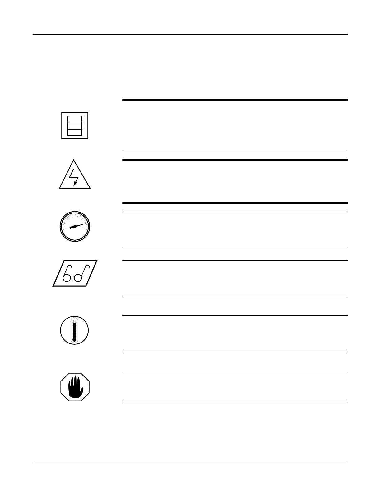
Solvents and Chemicals
High Voltage
High Pressure
Personal Protective
Equipment
WARNING: T
OPERATOR TO CERTAIN HAZARDS
TAKEN SO AS TO AVOID EXCEEDING THE
BEING USED
(OSHA)
PROTECTION AND PROPER HANDLING FROM THE SUPPLIER OF SUCH CHEMICALS
WARNING:
THE ELECTRIC CONSOLES OR OTHERWISE SERVICE THIS EQUIPMENT AND/OR EQUIPMENT USED
WITH IT BEFORE SWITCHING OFF THE MAIN POWER DISCONNECT AND INTERRUPTING SUPPLY
VOLTAGE AT THE SOURCE
A QUALIFIED ELECTRICIAN
WARNING:
CHEMICAL COMPONENTS CAPABLE OF PRODUCING UP TO
BODILY INJURY FROM INJECTION OF FLUID
COMPONENTS WITHOUT BLEEDING ALL PRESSURES TO ZERO
WARNING:
WHEN OPERATING, SERVICING, OR BEING PRESENT IN THE OPERATIONAL ZONE OF THIS
EQUIPMENT
SAFETY SHOES, AND RESPIRATORY EQUIPMENT AS REQUIRED
HE SOLVENTS AND CHEMICALS USED WITH THIS EQUIPMENT EXPOSE THE
. A
DEQUATE PERSONAL PROTECTIVE MEASURES MUST BE
T
HRESHOLD LIMIT VALUE
,
AS ESTABLISHED BY THE OCCUPATIONAL SAFETY AND HEALTH ADMINISTRATION
OR OTHER QUALIFIED AGENCY
. O
BTAIN INFORMATION CONCERNING PERSONAL
(TLV)
OF THE PRODUCTS
.
TO PREVENT SERIOUS BODILY INJURY FROM ELECTRICAL SHOCK, NEVER OPEN
. T
HE ELECTRICAL SERVICE MUST BE INSTALLED AND MAINTAINED BY
.
THIS EQUIPMENT HAS OR IS USED WITH EQUIPMENT THAT HAS HYDRAULIC AND
3500
PSI
. T
O AVOID SERIOUS
,
NEVER OPEN OR SERVICE ANY CONNECTIONS OR
.
TO AVOID SERIOUS BODILY INJURY, PROPER PROTECTIVE GEAR MUST BE WORN
. T
HIS INCLUDES, BUT IS NOT LIMITED TO, EYE AND FACE PROTECTION, GLOVES
.
,
WARNING: T
TEMPERATURE COMPONENTS SUCH AS PRIMARY HEATERS AND HEATED HOSES
SERIOUS BODILY INJURY FROM HOT FLUID OR HOT ME TAL
EQUIPMENT BEFORE ALLOWING IT TO COOL
HIS EQUIPMENT HAS OR IS USED WITH EQUIPMENT THAT HAS HIGH
. T
,
NEVER ATTEMPT TO SERVICE THE
.
O PREVENT
High Temperature
WARNING:
PERSONAL INJURY AND/OR DAMAGE TO THE EQUIPMENT FROM ONE OR MORE OF THE ABOVE
LISTED HAZARDS
FAILURE TO READ AND FOLLOW THIS SAFETY INFORMATION MAY RESULT IN
.
Warning
12/19/02 7
H-20/35 VR Series Proportioning Unit
DESCRIPTION
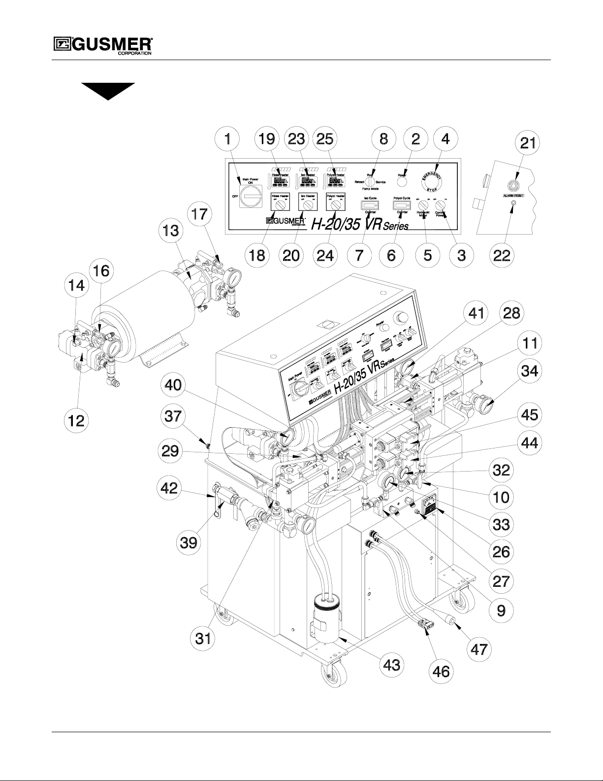
Figure 1. Major Components
8 42942-VR-1, Issue 1

Operating Manual Description
1. MAIN POWER DISCONNECT- Controls power to all circuits. Must be ON for
any function of the proportioning unit to operate. The disconnect can be locked in
the OFF position for OSHA required lockout/tagout during machine maintenance.
2. MAIN POWER LIGHT (WHITE)- Lights up when the Main Disconnect Switch is
in the ON position and the control power transformer is operational.
3. CONTROL POWER SWITCH- Turns the unit’s 120VAC control power circuit on
and off. In the ON position, the amber light within the switch lights up. Removal of
control power stops all machine operation including motion and heating.
4. EMERGENCY STOP SWITCH- Interrupts the units control power circuit to stop
all motion and heating. Switch mechanically locks in the stop position. Turn the
switch clockwise to reset it and restore normal operation.
5. HYDRAULIC MOTOR SWITCH- Controls power to motor circuit. In the ON
position, the green light within the switch lights up.
6. POLYOL COUNTER- Records the cycle count of the Polyol proportioning pump.
One cycle equals two strokes (one in each direction); used to determine ratio.
7. ISOCYANATE COUNTER- Records the cycle count of the Isocyanate
proportioning pump. One cycle equals two strokes (one in each direction); used to
determine ratio.
8. PUMP MODE SWITCH- Controls operation of the proportioning pump Hydraulic
Drive System
• RUN- Should be in this position for the pump system to operate properly.
This position is used for all normal operation of the pump system, while
dispensing chemical. Hydraulic system will be energized when a special
dispensing gun is triggered.
• RETRACT- The pump system is energized so that the Isocyanate pump
shaft is retracted into the pump cylinder. This shields the Isocyanate pump
shaft from air to limit crystallization during periods of machine inactivity.
The retract position should be used during any period of machine inactivity
• SERVICE – With the recirculating ball valves open, the pump system is
energized and ratio can be determined with the counters or material can be
conditioned. With the recirculating ball valves closed, the system will build
pressure.
9. ISOCYANATE RECIRCULATING BALL VALVE – Ball valve on the Iso
material that either allows the system to recirculate chemical back to the chemical
drums during Service Pump Mode or prevents chemical from returning to the
chemical drums during Run Pump Mode.
10. POLYOL RECIRCULATING BALL VALVE – Ball valve on the Polyol material
that either allows the system to recirculate chemical back to the chemical drums
during Service Pump Mode or prevents chemical from returning to the chemical
drums during Run Pump Mode.
12/19/02 9

H-20/35 VR Series Proportioning Unit
11. ACTIVATOR PLATE – Works with the reversing switches to change pump
direction.
12. HYDRAULIC PUMP (ISOCYANATE) – Hydraulic pump that supplies the
pressure and flow rate to the hydraulic drive system that attaches to the Isocyanate
proportioning pump.
13. HYDRAULIC PUMP (POLYOL) – Hydraulic pump that supplies the pressure and
flow rate to the hydraulic drive system that attaches to the Polyol proportioning
pump.
14. HYDRAULIC PUMP FLOW ADJUSTMENT (ISOCYANATE) – Adjustme nt
allows the flow rate of the hydraulic pump to be increased or decreased, which
increases or decreases output of the Isocyanate pump.
15. HYDRAULIC PUMP FLOW ADJUSTMENT (POLYOL) – Adjustment allows
the flow rate of the hydraulic pump to be increased or decreased, which increases or
decreases output of the Polyol pump. (Not Shown)
16. HYDRAULIC PUMP PRESSURE CONTROL ADJUSTMENT
(ISOCYANATE) – Controls the hydraulic pressure available to the Hydraulic Drive
System. This adjustment must be set high enough so the pump will not reduce flow
rate for the Isocyanate pump.
17. HYDRAULIC PUMP PRESSURE CONTROL ADJUSTMENT (POLYOL) –
Controls the hydraulic pressure available to the Hydraulic Drive System. This
adjustment must be set high enough so the pump will not reduce flow rate for the
Polyol pump.
18. HOSE HEATER SWITCH- Energizes the Hose Heat System circuit. In the ON
position, the green light within the switch lights up.
19. HOSE HEAT TEMP ERATURE CONTROLLER- Digital display of controller
will be energized when Control Power Switch is activated. Controller will display set
point temperature. Press the “SET” button to display the process temperature.
Display will shift back to set point after 10 seconds. The Hose Heater Switch must
be in the ON position before heating process will begin.
20. ISOCYANATE PRIMARY HEATER SWITCH- Energizes the Iso Primary
Heater system circuit. In the ON position, the green light within the switch lights up.
21. ALARM- Audible alarm that sounds when a low or over-pressure condition occurs.
22. ALARM RESET- Momentary switch that silences alarm after a low or overpressure condition occurs.
23. ISOCYANATE PRIMARY HEATER TEMPERATURE CONTROLLER-
Digital display of controller will be energized when Control Power Switch is
activated. Controller will display set point temperature. Press the "SET" button to
display the process temperature. Display will shift back to set point after 10 seconds.
Iso Primary Heater Switch must be in the ON position before heating process will
begin.
10 42942-VR-1, Issue 1

Operating Manual Description
24. POLYOL PRIMARY HEATER SWITCH- Energizes the Polyol Primary Heater
system circuit. In the ON position, the green light within the switch lights up.
25. POLYOL PRIMARY HEATER TEMP ERATURE CO NTROLLER- Digital
display of controller will be energized when Control Power Switch is activated.
Controller will display set point temperature. Press the "SET" button to display the
process temperature. Display will shift back to set point after 10 seconds. Polyol
Primary Heater Switch must be in the ON position before heating process will begin.
26. HOSE HEAT AMMETER- Displays the amperage (power) flowing in the Hose
Heat System.
27. HOSE HEAT POWER SET- Controls and adjusts the amount of amperage in the
Hose Heat System. Loosen lock nut before adjusting potentiometer. Tighten lock
nut after adjustment is completed.
28. POLYOL OVER-PRESSUR E SA FETY SWITCH- Turns off the Hydraulic Drive
System when the Polyol Proportioning Pump exceeds the safe pressure limitation.
29. ISOCYANATE OVER-PRESSURE SAFETY SWITCH- Turns off the Hydraulic
Drive System when the Isocyanate proportioning pump exceeds the safe pressure
limitation.
30. POLYOL LOW-PRESSURE SAFETY SWITCH- Turns off the Hydraulic Drive
System when the Polyol proportioning pump falls below 40 psi. (Not Shown)
31. ISOCYANATE LOW-PRESSURE SAFETY SWITCH- Turns off the Hydraulic
Drive System when the Isocyanate proportioning pump falls below 40 psi.
32. POLYOL PRESSURE GAUGE- Indicates the pressure in the Polyol proportioning
system.
33. ISOCYANATE PRESSURE GAUGE- Indicates the pressure in the Isocyanate
proportioning system.
34. POLYOL INLET PRESSURE GAU GE- Indicates the inlet pressure prior to the
Polyol proportioning system.
35. ISOCYANATE INLET PRESSURE GAUGE- Indicates the inlet pressure prior to
the Isocyanate proportioning system
36. POLYOL BULKHEAD RECIRCULATING FITTING- Fitting provides a means
of returning chemical back to drum via a return hose. (Not Shown)
37. ISOCYANATE BULKHEAD RECIRCULATING FITTING- Fitting provides a
means of returning chemical back to drum via a return hose.
38. POLYOL INLET SUPPLY B ALL VALVE- Allows delivery of Polyol to the
proportioning unit. (Not Shown)
39. ISOCYANATE INLET SUPPLY BALL VALVE- Allows delivery of Isocyanate
to the proportioning unit.
40. HYDRAULIC PRESSURE GAUGE - Indicates the pressure in the Hydraulic Drive
System for the Isocyanate pump.
12/19/02 11

H-20/35 VR Series Proportioning Unit
41. HYDRAULIC PRESSURE GAUGE- Indicates the pressure in the Hydraulic Drive
System for the Polyol pump.
42. HYDRAULIC TANK LEVEL GAUGE- Shows the level of oil in the tank.
43. LUBE PUMP SYSTEM (Iso side only)- Continuously circulates Pump Lube t o
prevent the crystallization of Isocyanate on the pump shaft.
44. HYDRAULIC DIRECTIONAL VALVE (ISO) - Controls the direction of
hydraulic flow.
45. HYDRAULIC DIRECTIONAL VALVE (POLYOL) - Controls the direction of
hydraulic flow.
46. HOSE HEAT POWER LOCK CONNECTOR- Provides power to the Heated
Hoses.
47. TSU HARNESS- Carries the electrical signal from the TSU Sensor in the Iso Hose
to the Hose Heat Temperature Controller.
48. HOSE HEAT SYSTEM SOLID
STATE RELAY (SSR)- The Hose
Heat System SSR is controlled by the
Hose Heat Temperature Controller.
The SSR acts as a switch allowing
current to flow in the Hose Heat
System Heating Element as required
by the Temperature Controller.
49. HOSE HEAT SSR JUMPER- The
jumper is used to bypass the hose
heat system SSR in the event that the
SSR fails. This allows continued to
operation of the machine by running
the Hose Heat System manually.
(See step 10 on page 32.)
Figure 2. Transformer Compartment
Electrical Components
50. HOSE HEAT SYSTEM CIRCUIT BREAKER- A 50-amp circuit breaker that
protects the Hose Heat System by limiting current to the Hose Heat Element.
51. CONTROL CIRCUIT TRANSFORMER- Steps down the incoming line voltage
to 120 VAC for use by the control circuit system.
52. PHASE CONTROLLER- Used in conjunction with the hose heat transformer tap
settings to adjust and fine tune the amperage supplied to the hose heat system heating
elements.
53. HOSE HEAT SYSTEM TRANSFORMER- Steps down incoming line voltage to
lower voltages used t o heat various lengths of ho se.
54. HOSE HEAT SYSTEM TERMINAL BLOCK ASSEMBLY- Used to select hose
heat voltage of 15, 30, 45, 60, 75, or 90 VAC for various lengths of hose.
(See step 16 on page 24.)
12 42942-VR-1, Issue 1

Operating Manual Description
12/19/02 13
H-20/35 VR Series Proportioning Unit
14 42942-VR-1, Issue 1
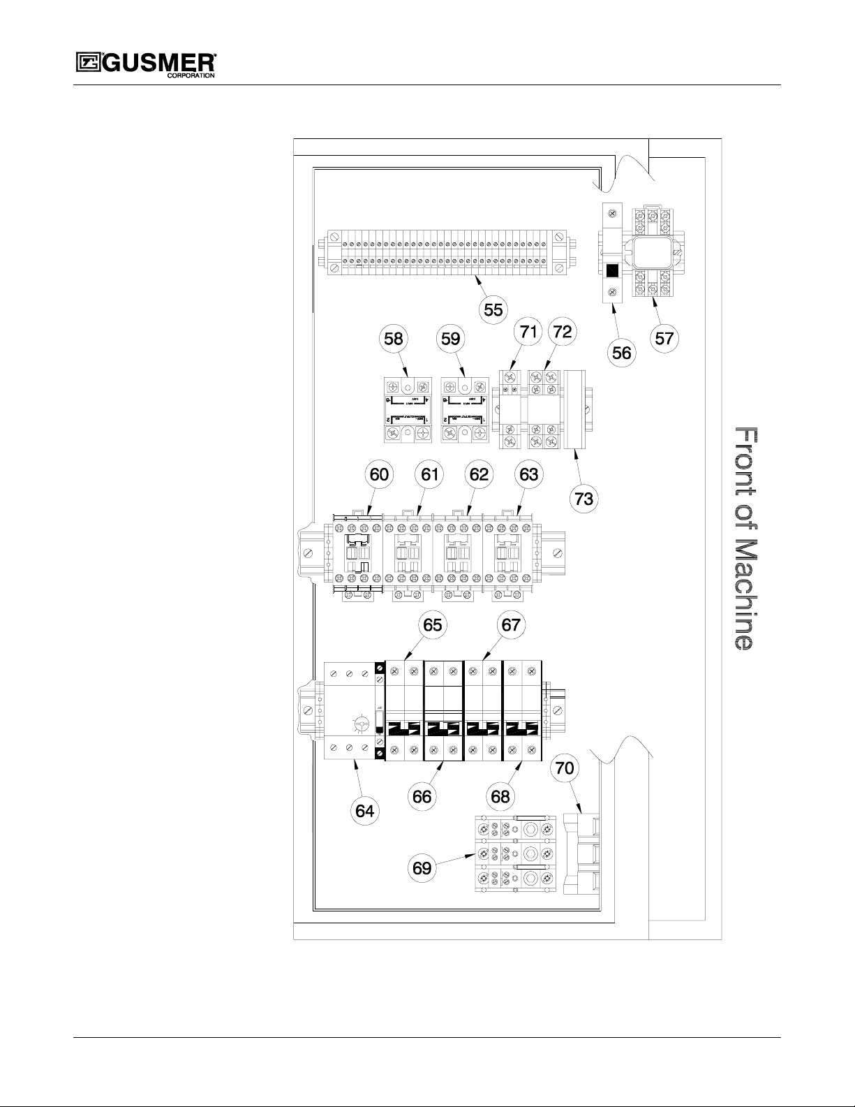
Figure 3. Electrical Console Components

Operating Manual Description
55. CONTROL MAIN TERMINAL BLOCK- Termination/distribution point for
control system component wires.
56. CONTROL TRANSFORMER SECONDARY CIRCUIT BREAKER- Provides
over-current protection for the control transformer secondary 120-volt AC output.
57. MASTER RELAY- Controls distribution of 120 volt AC to control power system.
The Control Power Switch energizes the relay.
58. ISOCYANATE HEATER CONTROL RELAY- Controls distribution of line
voltage Iso Primary heater circuit. The Iso Primary Heater Temperature Controller
controls the relay.
59. POLYOL PRIMARY HEATER CONTROL RELAY- Controls distribution of
line voltage to Polyol Primary heater circuit. The Polyol Primary Heater
Temperature Controller controls the relay.
60. MOTOR CONTACTOR- Supplies line voltage to electric motor. The Hydraulic
Motor Switch controls the contactor.
61. ISOCYANATE PRIMARY HEATER CONTACTOR- Supplies line voltage to
the Iso Primary Heater. The Iso Primary Heater Switch controls the contactor.
62. POLYOL PRIMARY HEATER CONTROL CONTACTOR- Supplies line
voltage to the Polyol Primary Heater, which controls the contactor.
63. HOSE HEAT CONTACTOR- Supplies line voltage to Hose Heat System. The
Hose Heater Switch controls the contactor.
64. MOTOR CIRCUIT PROTECTOR- Provides thermal overload and over-current
protection for the hydraulic motor circuit.
65. ISOCYANATE HEATER CIRCUIT BREAKER- Provides over-current
protection for the Iso Primary Heater circuit.
66. POLYOL PRIMARY HEATER CIRCUIT BREAKER- Provides over-current
protection for the Polyol Primary Heater circuit.
67. HOSE HEAT TRANSFORMER PRIMARY CIRCUIT BREAKER- Provides
over-current protection for the Hose Heat Transformer Primary circuit.
68. CONTROL TRANSFORMER PRIMARY CIRCUIT BREAKER- Provides
over-current protection for the hose transformer primary circuit.
69. POWER DISTRIBUTION BLOCK- Provides power distribution point for
incoming line voltage to the circuit breaker bank.
70. MAIN POWER DISCONNECT (Inside View)- Provides termination point for
incoming power. Disconnects incoming power from machine circuits.
71. GUN/PUMP CONTROL RELAY- Enables the pump directional valves to operate
when the gun is triggered.
72. ALARM RELAY – Controls the operation of the Audible Alarm and disables the
pump circuit when an over- or under-pressure condition occurs.
73. DISPENSING GUN FUSE – ½ amp fuse to protect the gun trigger circuit
12/19/02 15
 Loading...