

Page 1
"Teamwork & Communication"
Model GX-8
Operating Manual
Spray Gun
32943-1
April 21, 1999
Issue 1
GUSMER CORPORATION
A Subsidiary of Gusmer Machinery Group, Inc.
One Gusmer Drive
Lakewood, New Jersey, USA 08701-8055
Toll Free 1-800-367-4767 (USA & Canada)
Phone: (732) 370-9000
Fax: (732) 905-8968
Copyright 1999, GUSMER CORPORATION
http://www.gusmer.com
NOTICE: This manual contains important information for your GUSMER equipment. Read and retain for future reference.
®
®
Page 2

Model GX-8 Spray Gun
CONTENTS
LIST OF FIGURES..........................................................................................................3
WARRANTY ....................................................................................................................4
GENERAL SAFETYINFORMATION..........................................................................5
CCEPTABLEEQUIPMENT USES.......................................................................................5
A
O
PERATIONALSAFETY PROCEDURES...............................................................................6
DESCRIPTION.................................................................................................................7
EY FEATURES ................................................................................................................7
K
M
AJOR COMPONENTS......................................................................................................9
E
QUIPMENT SUPPLIED....................................................................................................10
G
UN SERVICE KITS........................................................................................................11
OPERATION..................................................................................................................12
AFETY POSITION OF GUN .............................................................................................12
S
M
ANUAL VALVES ..........................................................................................................12
A
IR LINE CONFIGURATION.............................................................................................13
S
TART-UP......................................................................................................................13
S
HUTDOWN....................................................................................................................14
CLEANING PROCEDURE...........................................................................................15
SERVICING PROCEDURES........................................................................................17
S
CREEN SCREW REMOVALAND SERVICE PROCEDURE ................................................. 17
C
ENTERLINE COMPONENT REMOVAL ............................................................................18
C
ENTERLINE COMPONENT INSTALLATION .....................................................................20
V
ALVINGROD ADJUSTMENT .........................................................................................21
A
IR PISTON O-RING AND CUP SEAL REPLACEMENT ......................................................23
E
ND CAP O-RING AND CUP SEAL REPLACEMENT..........................................................25
T
RIGGER VALVE O-RING REPLACEMENT.......................................................................27
APPENDIX......................................................................................................................29
PECIFICATIONS.............................................................................................................29
S
INSTRUCTION MANUAL DISCREPANCY REPORT............................................31
2 32943-1, Issue 1
Page 3

Operating Manual Contents
LIST OF FIGURES
FIGURE 1. MIXING MODULE..............................................................................................8
F
IGURE 2. MAJOR COMPONENTS .......................................................................................9
F
IGURE 3. CENTERLINE COMPONENTS...............................................................................9
F
IGURE 4. STANDARD TOOL KIT ......................................................................................10
F
IGURE 5. 1 QUART GUN SERVICE KIT (P/N OP205).......................................................11
F
IGURE 6. 3 GALLON GUN SERVICE KIT (P/N OP206).....................................................11
F
IGURE 7. ENGAGE THE SAFETY STOP..............................................................................12
F
IGURE 8. DISENGAGE THE SAFETY STOP ........................................................................12
F
IGURE 9. MANUAL VALVES ............................................................................................12
F
IGURE 10. CENTERLINE COMPONENTREMOVAL..............................................................18
F
IGURE 11. CENTERLINE COMPONENTINSTALLATION .......................................................20
F
IGURE 12. PCD SPACING..............................................................................................21
F
IGURE 13. VALVING ROD ADJUSTMENTS ........................................................................22
F
IGURE 14. END CAP/SAFETY STOP ASSEMBLYAND PISTON ASSEMBLY REMOVAL............. 24
F
IGURE 15. END CAP/SAFETY STOP ASSEMBLYREMOVAL .................................................26
F
IGURE 16. TRIGGER/AIR VALVE ASSEMBLY.....................................................................27
4/21/99 3
Page 4

Model GX-8 Spray Gun
WARRANTY
Gusmer Corporation (Gusmer) provides a limited warranty to the original purchaser (Customer) of
Gusmer manufactured parts and equipment (Product) against any defects in material or
workmanship for a period of one year from the date of shipment from Gusmer facilities.
In the event Pr oduct is suspected to be defective in material or workmanship, it must be returned to
Gusmer, freight prepaid. If Product is found to be defective in material or workmanship, as
determined solely by Gusmer, Gusmer will issue full credit to Customer for the freight charges
incurred in returning the defective Product, and either credit will be issued for the replacement cost
of the Product or a replacement part will be forwarded no-charge, freight prepaid to Customer.
This warranty shall not apply to Product Gusmer finds to be defective resulting from: installation,
use, maintenance, or procedures not accomplished in accordance with our instructions; normal
wear; accident; negligence; alterations not authorized in writing by Gusmer; use of “look alike”
parts not manufactured or supplied by Gusmer; or Product used in conjunction with any other
manufacturer's pumping or proportioning equipment. Further, the terms and conditions of this
warranty shall not apply to services or repairs madeto Product by any third party not authorized in
writing by Gusmer. For such Product, a written estimate will be submitted to Customer at a
nominal service charge, itemizing the cost for repair. Disposition of Product will be done in
accordance withthe terms stated on the written estimate.
The warranty provisions applied to product that are not manufactured by Gusmer will be solely in
accordance with the warranty provided by the original manufacturer of the product.
GUSMER MAKES NO WARRANTY WHATSOEVER AS TO THE MERCHANTABILITY OF,
OR SUITABILITY FOR, ITS PRODUCT TO PERFORM ANY PARTICULAR PURPOSE.
CREDIT FOR, OR REPLACEMENT OF, PRODUCT DEFECTIVE IN MATERIAL OR
WORKMANSHIP SHALL CONSTITUTE COMPLETE FULFILLMENT OF GUS MER
OBLIGATIONS TO CUSTOMER. NO OTHER WARRANTY, EXPRESSED OR IMPLIED ON
ANY PRODUCT IT MANUFACTURES AND/OR SELLS, WILL BE RECOGNIZED BY
GUSMER UNLESS SAID WARRANTY IS IN WRITING AND A PPROVED BY AN OFFICER
OF GUSMER.
Under no circumstances shall Gusmer be liable for loss of prospective or speculative profits, or
special indirect, incidental or consequential damages. Further, Gusmer shall have no liability for
anyexpensesincluding, but not limited to personal injury or property damage resultingfrom failure
of performance of the product, use of the product, or application of the material dispensed through
the product. Any information provided by Gusmer that is based on data received from a third
source, or that pertains to product not manufactured by Gusmer, while believed t o be accurate and
reliable, is presented without guarantee, warranty, or responsibility of any kind, expressed or
implied.
Gusmer through the sale, lease, or rental of Product in no way expresses or implies a license for the
use of, nor encourages the infringement of any patents or licenses.
To insure proper validation of your warranty, please complete the warranty card and return it to
Gusmer within two weeks of receipt of equipment.
Revised 11/12/98
4 32943-1, Issue 1
Page 5

Operating Manual General Safety Information
GENERAL SAFETY INFORMATION
It is necessary to understand and follow the instructions in this manual to insure proper
and safe operation of the equipment.
As withmost mechanical equipment, certain safetyprecautions must be taken when the
equipment discussed in this manual is operated or serviced. Severe bodily injury or
damage to equipment and property may result if the instructions and precautions listed
throughout this manual are not followed.
Needless to say, sufficient guidelines cannot be developed to eliminate the need for good
common sense in the use and servicing of this equipment, and in the use and application
of the products, this equipment has been designed to process. Users of this equipment
must therefore, make their own determination as to the suitability of the information
contained in this manual to their specific operation and requirements. There should be no
assumption made that the safetymeasures and instructions contained herein are allinclusive, and that other safety measures may not be required for specific use or
application.
The following safety guidelines are generally applicable to the safe and efficient use of
the equipment.
Acceptable Equipment Uses
The equipment is designed for the dispensing of polyurethane foams, two-component
coating systems, and some two-component epoxy systems, specificallypolyureas. Under
no circumstances should any acid or corrosive chemicals be used in the unit. Consult
GUSMER if there is any doubt about the compatibility of the chemical system to be used
in this equipment.
Any use of this equipment other than as indicated above constitutes misuse unless express
written approval is obtained from GUSMER.
4/21/99 5
Page 6
Model GX-8 Spray Gun
Operational Safety Procedures
This safety information will not be repeated in the text of this manual. The symbols
pertaining to this information will appear where appropriate to alert the operator to
potential hazards.
Solvents and Chemicals
High Voltage
High Pressure
Personal Protective
Equipment
WARNING: T
OPERATOR TO CERTAIN HAZARDS.ADEQUATE PERSONAL PROTECTIVE MEASURES MUST
BETAKEN SO AS TO AVOID EXCEEDING THE
PRODUCTS BEING USED
HE SOVENTS AND CHEMICAL USED WITH THIS EQUIPMENT EXPOSE THE
THRESHOLD LIMIT VALUE (TLV) OF THE
, AS ESTABLISHED BY THE OCCUPATIONAL SAFETY AND HEALTH
ADMINISTRATION (OSHA) OR OTHER QUALIFIED AGENCY.INFORMATION CONCERNING
PERSONAL PROTECTION AND PROPER HANDLING FROM THE SUPPLIER OF SUCH CHEMICALS
WARNING: T
THE ELECTRIC CONSOLES OR OTHERWISE SERVICE THIS EQUIPMENT AND/OR EQUIPMENT USED
WITH IT BEFORE SWITCHING OFF THE MAIN POWER DISCONNECT AND INTERRUPTING SUPPLY
VOLTAGE AT THE SOURCE
A QUALIFIED ELECTRICIAN
WARNING: T
COMPONENTS CAPABLE OF PRODUCING UP TO 3500 PSI.TO AVOID SERIOUS BODILYINJURY
FROM HYDRAULIC INJECTION OF FLUID
SERVICE HY DRAULICCOMPONENTS WITHOUT BLEEDING ALL PRESSURES TO ZERO
WARNING: T
WHEN OPERATING, SERVICING, OR BEING PRESENT IN THE OPERATIONAL ZONE OF THIS
EQUIPMENT
SAFETY SHOES, AND RESPIRATORYEQUIPMENT AS REQUIRED.
O PREVENT SERIOUS BODILY INJURY FROM ELECTRICAL SHOCK, NEVER OPEN
.THE ELECTRICAL SERVICE MUST BE INSTALLED AND MAINTAINED BY
.
HIS EQUIPMENT HAS OR IS USED WITH EQUIPMENT THAT HAS HYDRAULIC
, NEVER OPEN ANY HYDRAULIC CONNECTIONS OR
.
O AVOID SERIOUS BODILY INJURY, PROPER PROTECTIVE GEAR MUST BE WORN
.THIS INCLUDES, BUT IS NOT LIMITED TO, EYE AND FACE PROTECTION, GLOVES,
.
WARNING: T
TEMPERATURE COMPONENTS SUCH AS PRIMARY HEATERS AND HEATED HOSES.TO PREVENT
SERIOUS BODILY INJURY FROM HOT FLUID OR HOT METAL
EQUIPMENT BEFORE ALLOWING IT TO COOL
HIS EQUIPMENT HAS OR IS USED WITH EQUIPMENT THAT HAS HIGH
, NEVER ATTEMPT TO SERVICE THE
.
High Temperature
WARNING:F
PERSONAL INJURY AND/OR DAMAGE TO THE EQUIPMENT FROM ONE OR MORE OF THE ABOVE
LISTED HAZARDS
AILURE TO READ AND FOLLOW THIS SAFETY INFORMATION MAY RESULT IN
Warning
6 32943-1, Issue 1
Page 7

Operating Manual Description
DESCRIPTION
Key Features
The design and development of the Gusmer Model GX-8 Spray Gun represents the next
step in the evolution of spray coating technology that Gusmer originated over 35 years
ago. We believe the GX-8 Spray Gun is the only mechanical purge gun in the world that
allows the spraying of polyureas and hybrids at outputs in the 1-2 pound per minute
range. Its lower output, lighter weight, fewer parts, and reduced air consumption are just
a few of its innovative enhancements. Yet, the GX-8 maintains many of the unique
design characteristics of its direct predecessor, the GX-7. These unique characteristics
include mechanical purge, a variety of durable mixing modules, interchangeable Pattern
Control Discs (PCD), and Gusmer quality.
The GX-8 design has successfully combined the proven concepts of other Gusmer
mechanical purge, direct impingement guns w ith exciting new enhancements that provide
a completely new gun that delivers:
• Unmatched low output capabilities
• Smaller gun dimensions with a 37% reduction in weight
• Increased maneuverability specifically for open mold applications
• Easy operation
• Less expensive operation
The gun is available with a variety of PCD options designed to meet most applications
that require the spraying of fast chemical systems at lowoutputs. Both your authorized
Gusmer Distributor and Gusmer Sales Engineers are available to help determine what
configurations are best for your specific application. Please contact either for additional
information.
The GX-8 is a combination of newconcepts and existing Gusmer spray gun technology.
For example, the mixing module that is contained in the GX-8 is similar in function to the
GX-7 mixing module. However, it is very different in its final design. The module’s
modified geometry supports the mixing requirements of the extremely fast chemistries
found in polyureas and hybrid polyurethanes/polyurea. This coupled with a smaller
mechanical purge valving rod and smaller PCD insure proper mixing and timely delivery
of mixed product to the work surface. The PCD now comes standard with Gusmer’s
proprietary “gold tip” finish. This space age coating improves the non-sticking
characteristics of the tip, while simultaneously improving its durability. With improved
tip durability maintaining the spray pattern, whether round or fan shaped, for longer
periods is possible. This equates into longer tip life for the user.
The Mixing Module is the only part that requires routine replacement to insure proper gun
operation. This inexpensive plastic component will wear out through normal use. The
module incorporates a small alignment pin, which insures proper chemical port alignment
during insertion into the Gun Block. The Mixing Module is a precision-machined
component made of a proprietary engineering thermoplastic. It is cleaned using an air
pressurized Gun Cleaning Kit. However, even if irregularly serviced it can still be
cleaned using the appropriate drill bit. The Valving Rod is precision ground and made
from hardened tool steel. It is designed for long life and under normal use, will not
require routine replacement.
4/21/99 7
Page 8
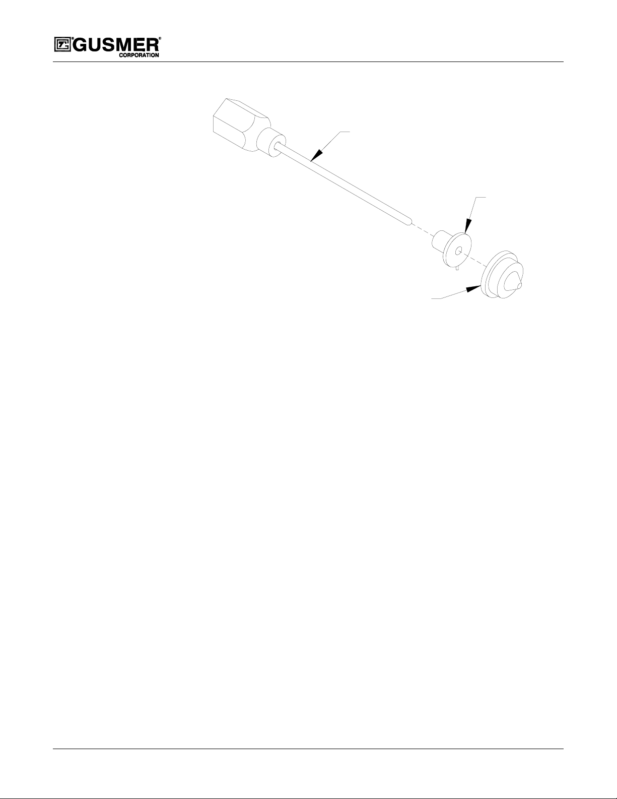
VALVING ROD
ASSEMBLY
PATTERN
CONTROL
DISC (PCD)
Figure 1. Mixing Module
Model GX-8 Spray Gun
MIXING
MODULE
The GX-8 has been designed for low output spraying performance, durability, reliability,
and serviceability. In order to enable the gun to dispense extremely low levels of
chemical, the Mixing Module has precision-machined chemical ports incorporated into it.
To protect these ports from clogging extremely fine screen mesh filters are used. Special
material coatings and material finishing techniques were also incorporated into the design.
A thorough understanding of this manual is essential to completely insure that this gun
provides the best service possible. In addition, the experience gained through daily use of
the gun will sharpen your operational and service skills. Functional problems can be
significantlyreduced by following the techniques and service recommendations described
in this manual.
Gusmer and our Authorized Distributors have experienced, highly qualified, technical
representatives who are always available to help if a problem does occur. In most cases, a
simple telephone call to our technical representatives will provide you with a solution to
your problem. Be sure to take advantage of their experience and expertise.
IMPORTANT: Substitution of parts not designed manufactured, or recommended by
Gusmer could result in harm to the user and/or damage to the GX-8 Gun. Any
alterations to or substitutions for Gusmer parts will void the warranty provisions set
forth elsewhere in this manual
8 32943-1, Issue 1
Page 9
Operating Manual Description
Major Components
In keeping with the need to gain a complete and thorough understanding of the
equipment, please take time to become familiar with the major components of the GX-8
Gun (Figure 2) and its Centerline Components (Figure 3). This will be helpful later when
these items are covered in the manual.
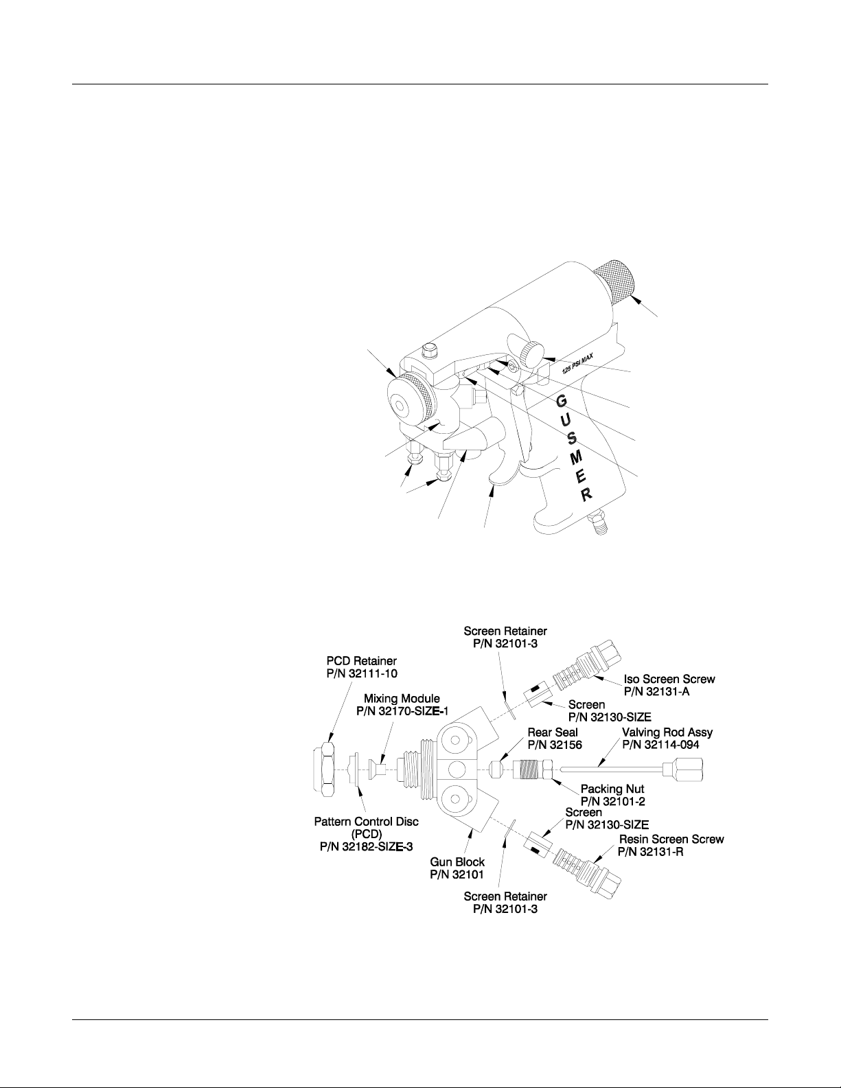
Safety Stop
Air Cap
Air Cap Air
Adjustment
Valve
Piston Rod
NOTE:
Both Round and Fan Mixing
Modules are available. The
Round Module provides a
round spray pattern and is
identified by a groove in its
cylindrical body. The Fan
Module provides a fan spray
pattern and is identified by its
smooth cylindrical body.
Gun Block
Manual Valves
CouplingBlock
Jam Nut
Valving Rod
Assembly
Trigger
Figure 2. Major Components
Figure 3. Centerline Components
4/21/99 9
Page 10
Model GX-8 Spray Gun
Equipment Supplied
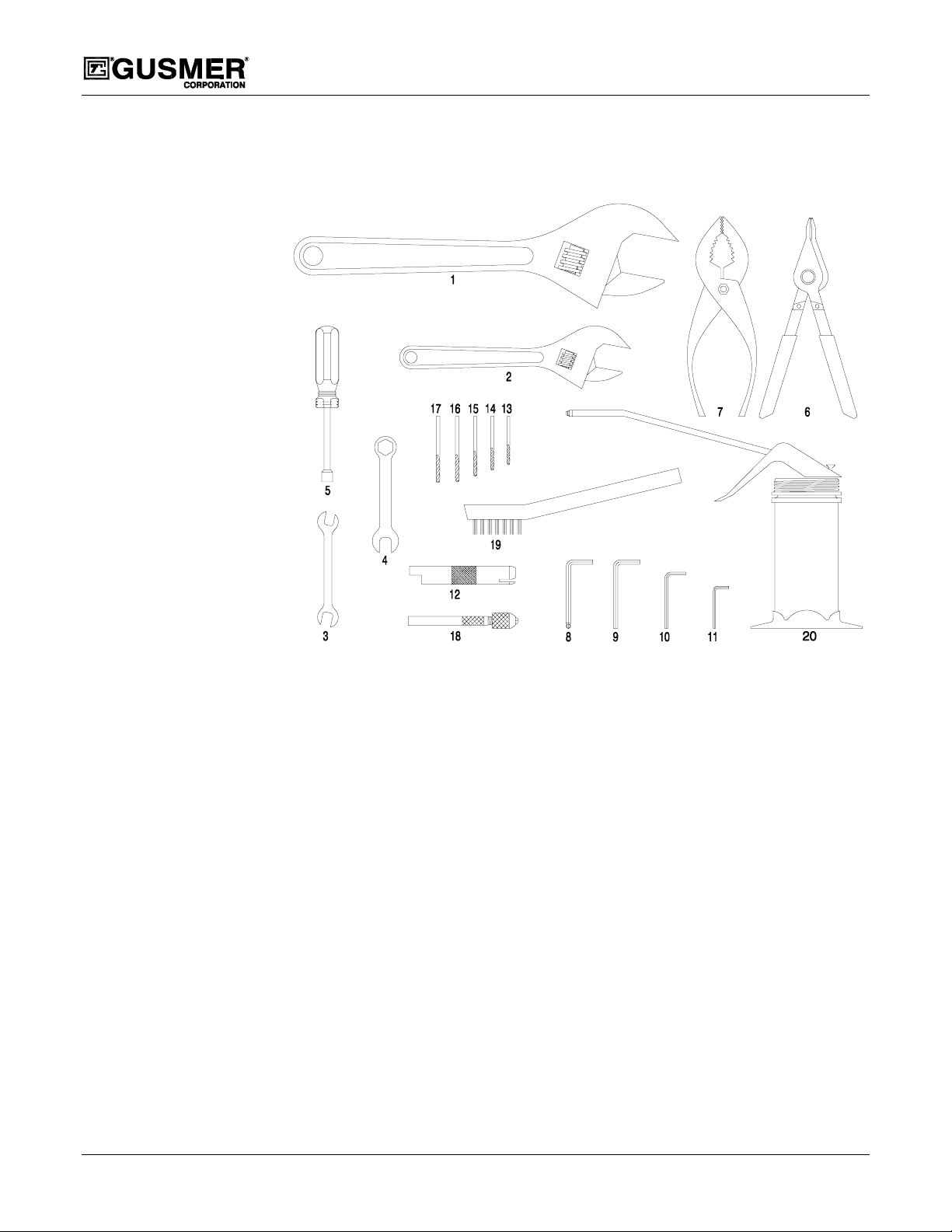
The Standard Tool Kit includes the following tools for use in servicing the GX-8.
Figure 4. Standard Tool Kit
1. 10” Adjustable Wrench (P/N 909A)
2. 6” Adjustable Wrench (P/N 0908)
3. 3/8” x 5/16” Open End Wrench
(P/N 1982A)
4. 1/2” Combination Wrench(P/N 1986)
5. 5/16” Spintite (P/N 0904A)
6. Retaining Ring 45°°°° Pliers (P/N 32982)
7. 6” Pliers (P/N 0906)
8. 9/64” Ball Point Hex Key
(P/N 0902-9/64)
9. 5/32” Hex Key (P/N 0902-5/32)
10. 3/16” Hex Key (P/N 0902-3/16)
11. 5/64” Hex Key (P/N 0902-5/64)
12. Check Valve Removal/Cleaning Tool
(P/N 1948)
13. #80 Clean Out Drill (.0135 Dia.)
(P/N 0941-45)
14. #68 Clean Out Drill (.031 Dia.)
(P/N 0941-22)
15. #60 Clean Out Drill (.040 Dia.)
(P/N 0941-29)
16. 1/8” Dia. Clean Out Drill
(P/N 0927-1/8)
17. 21/64” Dia. CleanOut Drill
(P/N 0927-21/64)
18. Pin Vise W/Collets (P/N 6902A)
19. Brush (P/N 1945)
20. Flush Can (P/N 0919A)
21. Lubriplate Grease
(P/N 0553-2) Not Shown
10 32943-1, Issue 1
Page 11

Operating Manual Description
Gun Service Kits
Cleaning the GX-8 with the 1 Quart Gun Service Kit (P/N OP205) or the 3 Gallon Gun
Service Kit (P/N OP206) is essential to the proper operation of the GX-8. Both kits are
available separately.
NOTE:
For more information
concerning the 1 Quart Gun
Service Kit consult the Parts
Identification Manual
(P/N OP205-ID).
NOTE:
For more information
concerning the optional,
3 Gallon Gun Service Kit (P/N
OP206) consult the Parts
Identification Manual
(P/N OP206-ID).
Figure 5. 1 Quart Gun Service Kit (P/N OP205).
Figure 6. 3 Gallon Gun Service Kit (P/N OP206)
4/21/99 11
Page 12

Model GX-8 Spray Gun
OPERATION
WARNING: NEVER POINT THE GUN AT OR NEAR OTHER PERSONNEL OR PLACE ANYPART OF
THE BODY IN THE PATH OF THE MATERIAL SPRAY AND DO NOTAT ANYTIME LOOK INTO THE
DISPENSING END OF THE GUN
STOP TO THE SAFETY OR SERVICE POSITION
AVOID THE POSSIBILITY OF PROPERTY DAMAGE OR BODILY INJURY FROM THE ACCIDENTAL
OPERATION OF THE GUN
Safety Position of Gun
The GX-8 has a two position Safety Stop. When engaged, it prevents accidental
triggering of the gun during servicing or down time. When disengaged, it allows the gun
to dispense.
1. ENGAGE THE SAFETY STOPPush in and turn the Safety Stop knob
clockwise to place the gun in the
Safety detented position.
.WHEN THE GUN IS NOT BEING USED, ALWAYS SET THE REAR
, AND CLOSE BOTH MANUAL VALVES .DOTHISTO
.
IMPORTANT: Always engage the
Safety Stop when the gun is not in use.
2. DISENGAGE THE SAFETY STOPPush in and turn the Safety Stop knob
counterclockwise to place the gun in
the Open detented position.
Manual valves
TOOLS REQUIRED
• 5/16” Spintite (P/N 0904A)
The GX-8 Coupling Block is equipped with
two Manual Valves which control the flow
of each chemical component to the gun.
Figure 7. Engage the Safety Stop
Figure 8. Disengage the Safety Stop
1. OP EN BOTH MANUAL VALVES-
Unnecessary triggering of the gun
NOTE:
with the manual valves closed
may cause crossover if there is
any residual chemical in the gun
ports.
Using the 5/16” Spintite, turn each
Manual Valve fully counterclockwise.
2. CLOSE BOTH MANUAL VALVESUsing the 5/16” Spintite, turn each
Manual Valve fully clockwise.
Figure 9. Manual Valves
12 32943-1, Issue 1
Page 13

Operating Manual Operation
IMPORTANT: To avoid accidental gun operation determine that the coupling block
manual valves have been closed before attempting to service the gun, or any time the
gun is not in use.
Air Line Configuration
TOOLS REQUIRED
• 3/16” Hex Key (P/N 0902-3/16)
• 6” Adjustable Wrench (P/N 0908)
The GX-8 air line connection can be configured in two different ways. The standard
configuration has the air connection at the base of the handle. The optional configuration
has the air connection at the rear of the gun. To change to the optional configuration
proceed as follows:
1. REMOVE THE 4“ LONG PIPE NIPPLE- Using the 6” Adjustable Wrench, remove
the 4“ long pipe nipple from the base of the Gun.
2. REMOVE THE 1/8” PIPE P LUG- Using the 3/16” Hex Key, remove the 1/8” pipe
plug from the rear of the gun.
Start-Up
NOTE:
If the GX-8 is shipped from the
factory withoutthe Mixing Module
andPCDinstalledtheValvingRod
will require adjustment. See the
Valving Rod Adjustment section of
the manual.
3. INSTALL THE 1/8” PIPE PLUG- Using the 3/16” Hex Key, install the 1/8” pipe
plug in the location previously occupied by the 4“ long pipe nipple.
4. INSTALL THE (OPTIONAL) SUPPLIED BRASS 1/8” NIPPLE- Using the 6”
Adjustable Wrench, install the supplied brass 1/8” nipple in the location previously
occupied by the 1/8” pipe plug.
TOOLS REQUIRED
• 5/16” Spintite (P/N 0904A)
IMPORTANT: Before attempting the following procedures, make sure the gun is
attached to the coupling block and air hoses, the proportioning unit is at the desired
temperature and pressure, and the system is ready for operation.
1. ADJUST THE AIR VALVE AIR ADJUSTMENT CAP CONTROL- The Knurled
knob on the Air Cylinder controls the amount of air that passes over the PCD. This
flow of air helps keep the PCD free of sprayed chemical. Too much air can
adversely effect spray pattern shape and create undesirable amounts of over-spray.
However, the airflow can be used to modify the spray pattern. Experiment to
determine what works best for the application.
Turn the knob Counter clockwise to open the valve and clockwise to close it.
2. OPEN BOTH MANUAL VALVES- Using the 5/16” Spintite, turn each valve fully
counterclockwise.
3. DISENGAGE THE SAFETY STOP- Push in and turn the Safety Stop knob
counterclockwise to place the gun in the Open detented position.
4. TEST SPRAY OFF TARGET
4/21/99 13
Page 14

Model GX-8 Spray Gun
Shutdown
TOOLS REQUIRED
• 5/16” Spintite (P/N 0904A)
IMPORTANT: Follow this procedure whenever the gun is out of service for any
length of time. For mid/end of day, service see the Cleaning Procedure section of this
manual.
1. ENGAGE THE SAFETY STOP- Push in and turn the Safety Stop knob clockwise to
place the gun in the Safety detented position.
2. CLOSE BOTH MANUAL VALVES- Using the 5/16” Spintite, turn each valve fully
clockwise.
Disassembling the gun daily for
NOTE:
cleaning is not recommended if it
has been operating properly.
However, experience will
determine whether disassembly is
necessary
3. CLEAN AS REQUIRED- See the Cleaning Procedure section of the manual.
IMPORTANT: As an additional safety precaution, the GX-8 air line has quick
disconnect air coupling. Disconnect the air line when transporting the gun with the
chemical hoses connected
14 32943-1, Issue 1
Page 15

Operating Manual Cleaning Procedure
CLEANING PROCEDURE
TOOLS REQUIRED
• 5/16” Spintite (P/N 0904A)
• 1 Quart Gun Service Kit (P/N OP205)
• Flush Can (P/N 0919A)
The Gun Block must be thoroughly cleaned with Gun Cleaner before removing the
Valving Rod or mixing components from the Gun Block. In this way, the residue left
from the two components will be completely diluted with Gun Cleaner and will not react
with one another when the Gun Block components are removed.
This procedure makes use of the 1 Quart Gun Service Kit (P/N OP205) and is the
recommended procedure for several reasons:
1) The cleaning is more efficient and uses less Gun Cleaner.
2) The gun does not have to be disassembled.
3) It can be used as a quick and efficient end of day procedure.
The 3 Gallon Gun ServiceKit (P/N OP206) is also available for cleaning the GX-8.
WARNING: PROPERLYGROUND ALL EQUIPMENT INVOLVEDIN THE CLEANING OPERATION
TO AVOID STATIC SPARKING WHICHCOULD RESULT IN FIRE OR EXPLOSION.DO NOT CLEAN ON
OR NEAR FOAMED OR COATEDSURFACES
.
WARNING: WHENSERVICING OR OPERATING THE GX-8, SUFFICIENT PROTECTIVE CLOTHING
MUST BE WORN TO PREVENT PROLONGED SKIN CONTACT WITH THECHEMICALS OR SOLVENTS
USED IN OR WITH THE GUN
A
LWAYS WEAR APPROVED SAFETY GLASSES OR GOGGLES,GLOVES, AND RESPIRATORY
EQUIPMENT WHEN SERVICING OR OPERATING THE
.
GX-8.
1. CLOSE BOTH MANUAL VALVES- Using the 5/16” Spintite, turn each Manual
Valve fully clockwise.
2. ENGAGE THE SAFETY STOP- Push in and turn the Safety Stop knob clockwise to
place the gun in the Safety detented position.
3. REMOVE THE GUN FROM THE COUPLING BLOCK- Using the 5/16" Spintite;
remove the Coupling Block Mounting Screw. Separate the gun from the Coupling
Block. Using a rag soaked with Gun Cleaner wipe clean the face of the Coupling
Block to prevent material build-up.
4. ATTACH THE SERVICE BLOCK OF THE GUN SERVICE KIT TO THE GUN–
Using the 5/16” Spintite; fasten the Service Block to the gun. Pressurize the
container to 100 psi.
4/21/99 15
Page 16

Model GX-8 Spray Gun
Opening one manual valve at a
NOTE:
time will allow flushing of
individual chemicals. This is
useful when flushing high
viscosity materials and insures
maximum effectiveness in purging
the gun of chemical.
5. CLEAN THE GUN
a) Open either one of the Manual Valves on the Service Block
b) Disengage the Safety Stop by pushing in and turning the Safety Stop
Knob counterclockwise to place the gun in the Open detented position.
c) Trigger the Gun Service Kit and the Gun simultaneously catching the
Gun Cleaner in an appropriate container.
(A fine, unobstructed mist of cleaner should exit the Tip.)
d) Release both triggers and close the Manual Valves on the Service
Block.
e) Repeat the P rocedure for the other side of the Gun.
6. REMOVE THE SERVICE BLOCK OF THE GUN SERVICE KIT FROM THE
GUN– Using the 5/16” Spintite; disconnect the Service Block from the gun.
7. CLEAN SCREENS AND SCREEN SCREW- Using the Flush Can, flush out the
Screens and the Screen Screw Cavities completely
.SeetheScreen Screw Service
Procedure section of this manual
Important: At this time it is a good idea to inspect the Air Cap, PCD, Module, and
Gun Block for build up of material and clean them as required.
16 32943-1, Issue 1
Page 17

Operating Manual Servicing Procedures
SERVICING PROCEDURES
Screen Screw Removal And Service Procedure
TOOLS REQUIRED
• 3/8” x 5/16” Open End Wrench (P/N 1982A)
• 1/8” Dia. (P/N 0927-1/8) Clean Out Drill
• 21/64” Dia. (P/N 0927-21/64) Clean Out Drill
• Pin Vise W/Collets (P/N 6902A)
• Flush Can (P/N 0919A)
WARNING:
KIT PRIOR TO REMOVAL FOR SERVICING AS THEYARE EXPOSED TO THE CHEMICAL.SEE THE
CLEANING PROCEDURES SECTION OF THIS MANUAL.
1. REMOVE THE SCREEN SCREW ASSEMBLY- Using the 3/8” x 5/16” Open End
Wrench, unthread the Screen Screw fromthe Gun Block. Remove the Screen Screw
retainer, the small ring-like part at the bottom of the screen, before removing the
screen. Remove the Retainer by hand. Now, slide off the Screen. If there are solid
particles attached to the Screen, attempt to soak the screen in Gun Cleaning Solvent.
However, if the screen is especially dirty and clogged, it is better to replace it.
2. CLEAN THE SCREEN SCREW CAVITY- Inspect the cavity, if any
visible remove themwith a combination of the Clean Out Drills mentioned above and
Cleaning Solvent.
WARNING:
WILL GO DIRECTLY INTO THE MODULE AND PROBABLY CLOG IT.
3. REPLACE THE SCREEN SCREW- Using the 3/8” x 5/16” Open End Wrench,
replace the Screen Screw. Make sure the screw is tight to insure the integrity of this
metal to metal seal.
4. CLEAN THE GUN- Clean the gun after cleaning the Cavities and Screens. See the
Cleaning Procedure section of this manual. In this case, flush the gun with the
module removed. This insures that all particles are expelled from the gun block and
prevents blockage of the module ports.
BE SURE TO CLEAN THE “CENTER LINE COMPONENTS” USING THE GUN SERVICE
particles are
ANY MATERIAL LEFT IN THE CAVITY ON THE DOWNSTREAM SIDE OF THE SCREEN
4/21/99 17
Page 18

Centerline Component Removal
TOOLS REQUIRED
• 10” Adjustable Wrench (P/N 909A)
• 3/8” x 5/16” Open End Wrench (P/N 1982A
• 1/2” Combination Wrench (P/N 1986)
• 5/16” Spintite (P/N 0904A)
• Lubriplate Grease (P/N 0553-2)
The Center Line Components consist of the following:
Screen Retainer
PCD Retainer
Mixing Module
Rear Seal
Screen
Valving Rod
Assembly
Model GX-8 Spray Gun
Iso Screen
Screw
Packing Nut
Pattern Control Disc
(PCD)
Gun Block
Screen
Resin Screen
Screw
Jam Nut
Screen Retainer
Figure 10. Centerline Component Removal
WARNING: DISCONNECT THE CHEMICAL HOSES AND AIRLINEBEFORE SERVICING THE GUN.
IN ADDITION, BE SURE TO CLEAN THE “CENTER LINE COMPONENTS” WITH THE GUN SERVICE
KIT PRIOR TO REMOVAL FOR SERVICING AS THEY ARE EXPOSED TO THE CHEMICAL
1. CLOSE BOTH MANUAL VALVES- Using the 5/16” Spintite, turn each Manual
Valve fully clockwise.
2. ENGAGE THE SAFETY STOP- Push in and turn the Safety Stop knob clockwise to
place the gun in the Safety detented position.
3. REMOVE THE AIR CAP- Rem ove the Air Cap by hand.
4. REMOVE PCD RETAINER-Use the 10” Adjustable Wrench, to remove the PCD
Retainer.
5. REMOVE THE PATTERN CONTROL DISC (PCD)- Lift the PCD off the nose of
the Gun Block.
18 32943-1, Issue 1
Page 19

Operating Manual Servicing Procedures
Important: To free a PCD that appears to be stuck, set the Safety Stop to the Open
position, then depress and release the gun trigger to unseat it.
6. REMOVE THE MIXING MODULE- Reconnect the air line. Disengage the Safety
Stop and depress the trigger and release. The Mixing Module should unseat itself
from the Gun Block. Lift the Mixing Module off the end of the Valving Rod.
Engage the Safety Stop and disconnect the air line.
Important: Do not attempt to dig out the Module using knives or sharp objects.
7. LOOSEN THE PACKING NUT-Using the 5/16” Wrench, back out the Packing Nut
threeorfourturns.
NOTE:
By removing the Packing Nut
entirely the Rear Seal can be
removed and replaced.
8. REMOVE THE GUN BLOCK- Using the 5/16” Spintite, remove the Gun Block
Retaining Screw. Carefully slide the Gun Block away from the Valving Rod and Air
Cylinder. If dried chemical has built up on the Gun Block removal may be difficult.
Removing the dried chemical will make removal easier. Be careful not to lose the
small “O” Ring seal located in the top if the Gun Block.
9. REMOVE THE VALVING ROD- Using the 3/8” Wrench, on the hex shaped
Valving Rod Shank and the ½” Wrench on the Jam Nut loosen the Jam Nut by
turning it clock wise. (As viewed from the front of the gun.) Continue to back the
Jam Nut away from the Valving Rod Shank by three or four full turns. Remove the
Valving Rod by unthreading it from the Piston Assembly.
10. CLEAN ALL COMPONENTS THOROUGHLY BEFORE REASSEMBLY- Using
the appropriate Brass Brushes, Clean Out Drills, etc. remove residual chemical. Use
Cotton Swabs soaked with Gun Cleaner if necessary. W hen finished, coat the
threads and the mating surfaces
of the Gun Block, Gun Block Bracket, and Gun with
Lubriplate Grease. Do not get any grease in the chemical ports located in the Gun
Block or Mixing Module as this could interfere with chemical flow.
11. INSPECT THE GUN BLOCK- It is important to keep the Gun Block clean and free
from damage to insure proper operation of the Spray Gun. It has been coated with a
proprietary coating to help protect it fromdamage and make it more difficult for
chemical to adhere to it. However, it still requires periodic attention.
4/21/99 19
Page 20

Centerline Component Installation
TOOLS REQUIRED
• 10” Adjustable Wrench (P/N 909A)
• 3/8” x 5/16” Open End Wrench (P/N 1982A
• 1/2” Combination Wrench (P/N 1986)
• 5/16” Spintite (P/N 0904A)
The Center Line Components consist of the following:
Screen Retainer
PCD Retainer
Mixing Module
Rear Seal
Screen
Valving Rod
Assembly
Model GX-8 Spray Gun
Iso Screen
Screw
Packing Nut
Pattern Control Disc
(PCD)
Gun Block
Screen
Resin Screen
Screw
Jam Nut
Screen Retainer
Figure 11. Centerline Component Installation
1. INST ALL THE VALVING ROD- Thread the Jam Nut as far back on the Piston Rod
as possible. Screwthe shank end of the Valving Rod onto the threaded end of the
Piston Rod.
2. INSTALL THE GUN BLOCK- Carefully slide the Gun Block onto the Valving Rod
towards the Air Cylinder. Using the 5/16” Spintite, install the Gun Block onto the
Gun Block Mounting Bracket.
3. INSTALL THE MIXING MODULE- With the air line connected, depress the Gun
Trigger Lever and slide the Mixing Module over the end of the Valving Rod while
making sure its alignment pin enters the alignment slot in the Gun Block. Keep the
Gun Trigger Lever depressed and proceed to Step 4.
Important: It is extremely important that these parts align properly. If they do not
the chemical flow from the Gun Block ports will not enter the Mixing Module when
triggering the gun
4. INSTALL THE PATTERN CONTROL DISC (PCD)- Maintain the Gun Trigger
Lever in the depressed position and place the PCD over the Mixing Module while
making sure the slot in the tip aligns with the Mixing Module alignment pin. If
installing a fan tip decide what orientation the fan spray pattern needs (vertical or
horizontal), and orient the PCD appropriately. Keep the Gun Trigger Lever
depressed and proceed to Step 5.
20 32943-1, Issue 1
Page 21

Operating Manual Servicing Procedures
5. INSTALL THE PCD RET AINER- With the Gun Trigger Lever depressed, thread
the PCD Retainer in place by hand. Using the 10” Adjustable Wrench carefully
tighten the PCD Retainer until it is “snug” to insure no leaking will occur when
pressurized chemical is introduced in to the gun. Release the Trigger.
Gun Block
WARNING:OVER TIGHTENING, THE PCD RETAINER
WILL CAUSE DAMAGE TO BOTH THE MODULE AND THE
GUN BLOCK.
Module
PCD
Important: When installing the Mixing Module
and/or the PCD a space approximately the
thickness of a business card should be between
the PCD and the tip of the Gun Block.
6. INSTALL THE AIR CAP- Thread the Air Cap
Space
in place by hand.
Figure 12. PCD Spacing
7. ADJUST THE VALVING ROD- See the Valving Rod Adjustment section of this
manual
Valving Rod Adjustment
TOOLS REQUIRED
• 3/8” x 5/16” Open End Wrench (P/N 1982A)
• 1/2” Combination Wrench (P/N 1986)
• 5/16” Spintite (P/N 0904A)
The GX-8 Valving Rod should not require adjustment if it was shipped from the factory
with the Mixing Module and Spray Tip installed. The Valving Rod will require adjusting
in the following instances:
• Changing a Piston/Rod assembly/replace O-Ring
• Changing a Valving Rod
• Installing or changing a Spray Tip
• Installing or changing a Mixing Module
WARNING: DISCONNECT THE CHEMICAL HOSES AND AIRLINEBEFORE SERVICING THE GUN.
IN ADDITION, BE SURE TO CLEAN THE “CENTER LINE COMPONENTS” WITH THE GUN SERVICE
KIT PRIOR TO REMOVAL FOR SERVICING AS THEYARE EXPOSED TO THE CHEMICAL
1. ENGAGE THE SAFETY STOP- Push in and turn the Safety Stop knob clockwise to
place the gun in the Safety detented position.
2. CLOSE BOTH MANUAL VALVES- Using the 5/16” Spintite, turn each Manual
Valve fully clockwise.
4/21/99 21
Page 22

Model GX-8 Spray Gun
3. REMOVE THE GUN FROM THE COUPLING BLOCK- Using the 5/16" Spintite;
remove the Coupling Block Mounting Screw. Separate the gun from the Coupling
Block. Using a rag soaked with Gun Cleaner wipe clean the face of the Coupling
Block to prevent material build-up.
4. PRESSURIZE THE AIR
CYLINDER- After making sure that
the Safety Stop is engaged, connect
the air line from the gun to the air
source.
5. LOOSEN REAR PACKING NUTUsing the 5/16” Open-End Wrench,
back out the Packing Nut three or
four turns. This will eliminate the
contact pressure between the Seal,
located inside the Packing Nut, and
the Valving Rod. With the pressure
relieved, the Valving Rod will move
freely making the adjustment
procedure easier to perform.
Figure 13. Valving Rod Adjustments
6. LOOSEN THE JAM NUT- Using the 3/8” Wrench, on the hex shaped Valving Rod
Shank and the ½” Wrench on the Jam Nut loosen the Jam Nut by turning it
clockwise. (As viewed from the front of the gun.) Continue to back the Jam Nut
away from the Valving Rod Shank by three or four full turns. Now move the
Valving Rod towards the Gun Cylinder by turning the Valving Rod Shank 2 or 3 full
turns clockwise.
7. ADJUST VALVING ROD CLEARANCE- Slowly turn the Valving Rod counter
clockwise, moving it forward towards the Spray Tip until resistance is felt. Go no
further. The Valving Rod Tip contacting the inside spherical surface of the PCD
causes this resistance.
8. LOCK ADJUSTMENT IN PLACE- While carefully maintaining the position of the
3/8” Wrench; tighten the Jam Nut up against the Valving Rod Shank.
9. RETIGHTEN THE PACKING NUT- Using the 3/8” x 5/16” Open End Wrench,
retighten the Packing Nut.
10. CHECK THE REAR SAFETY STOP- Disengage the Safety Stop by pushing in and
turning the knob counter clockwise. If the knob will not turn, the Valving Rod is
adjusted too far forward. Repeat step 6 and 7 making sure not to adjust the Valving
Rod past the point where resistance is felt. Once the SafetyStop moves freely,
proceed to step 11.
11. CONFIRM REAR SEAL ADJUST MENT- With the Safety Stop disengaged trigger
the gun. Make sure the Valving Rod moves freely. If it does not, loosen the Packing
Nut slightly until it does. Once spraying has started, make sure there is no chemical
weeping from the Packing Nut. If there is, retighten it slightly.
22 32943-1, Issue 1
Page 23

Operating Manual Servicing Procedures
Air Piston O-Ring and Cup Seal Replacement
TOOLS REQUIRED
• 3/8” x 5/16” Open End Wrench (P/N 1982A)
• 1/2” Combination Wrench (P/N 1986)
• RetainingRing 45º Pliers (P/N 32982)
• 6” Pliers (P/N 0906)
• 9/64” Ball Point Hex Key (P/N 0902-9/64)
• 5/32” Hex Key (P/N 0902-5/32)
• 3/16” Hex Key (P/N 0902-3/16)
• 5/16” Spintite (P/N 0904A)
NOTE:
If only the End Cap O-Ring
requires replacement see the
End Cap O-Ring and Cup Seal
Replacement section of this
manual.
WARNING: D
ISCONNECT THE CHEMICAL HOSES AND AIRLINE BEFORE SERVICINGTHE GUN.
IN ADDITION, BE SURE TO CLEAN THE “CENTER LINE COMPONENTS” WITH THE GUN SERVICE
KIT PRIOR TO REMOVAL FOR SERVICING AS THEYARE EXPOSED TO THE CHEMICAL
1. CLOSE BOTH MANUAL VALVES- Using the 5/16” Spintite, turn each Manual
Valve fully clockwise.
2. REMOVE THE GUN FROM THE COUPLING BLOCK- Using the 5/16" Spintite,
remove the Coupling Block Mounting Screw. Separate the gun from the Coupling
Block. Using a rag soaked with Gun Cleaner, wipe clean the face of the Coupling
Block to prevent material build-up.
3. CLEAN THE GUN- See the Cleaning Procedure section of this manual.
4. DISCONNECT AIR SUPPLY FROM GUN
5. LOOSEN PACKING NUT- Using the 3/8” x 5/16” Open End Wrench, loosen the
Packing Nut.
6. REMOVE GUN BLOCK SCREW- Using the 5/16” Spintite, remove the Gun Block
Screw.
7. REMOVE GUN BLOCK- Pull Gun Block off Valving Rod being careful not to bend
the Valving Rod.
8. REMOVE THE VALVING ROD- Using the 3/8” Wrench, on the hex shaped
ValvingRodShankandthe½”WrenchontheJamNut. LoosentheJamNutby
turning it clock wise. Continue to back the Jam Nut awayfrom the Valving Rod
Shank by three or four full turns. Remove the Valving Rod by unthreading the
Valving Rod from the Piston Rod. Remove the Jam Nut from the Piston Rod
9. DISENGAGE THE SAFETY STOP- Push in and turn the Safety Stop knob
counterclockwise to place the gun in the Open detented position.
4/21/99 23
Page 24

Model GX-8 Spray Gun
10. REMOVE SCREW- Using the 9/64” Ball Point Hex Key remove the rear #8 Socket
Head Screw that connects the Air Cylinder to the Handle. Remove only this screw.
#8 Socket Head
Cap Screw
Piston Assembly
End Cap/
Safety Stop
Assembly
Piston
Spring
Retaining Ring
NOTE:
Removing the End Cap will
require some force since the
O-Ring is tightly compressed
Figure 14. End Cap/Safety Stop Assembly and Piston Assembly Removal
11. REMOVE THE RETAINING RING- Using the Retaining Ring 45º Pliers remove
the Retaining Ring, which maintains the End Cap position in the Air Cylinder.
12. REMOVE THE END CAP/SAFETY STOP ASSEMBLY- Pull the Safety Stop until
it, and the attached End Cap come free from the Air Cylinder. Be sure to retain the
Piston Spring located inside of the Air Cylinder for future use.
13. INSPECT THE END CAP O-RING- Inspect the O-Ring. If necessary remove it and
install a newO-Ring after lightly coating it with Lubriplate Grease.
14. REMOVE THE PISTON/ROD ASSEMBLY- A second function of the Gun Block
Screw (the screw that holds the Gun Block to the Bracket) is to aid in the removal of
the Piston. The Piston is visible from the rear of The Air Cylinder. Thread the Gun
Block Screw into the hole in the center of the Piston at least four full turns. Using the
6” Pliers take hold of the Gun Block Screw and pull the Piston/Rod Assembly out of
the Air Cylinder. Inspect the O-Ring for damage and remove it if required.
Carefully reinstall the new O-Ring after applying Lubriplate Grease, taking care not
to damage it.
15. REPLACE CUP SEAL-Remove and replace the Cup Seal located in the front of the
air cylinder if air is escaping around the piston rod during operation. Lubricate the
new cup seal and install it making sure to that the “cup” is facing towards the rear of
the air cylinder.
16. REASSEMBLY OF THE PISTON INTO THE AIR CYLINDER - Insert the Piston
and Rod Assembly into the Air cylinder. Be careful not to damage the cup seal in the
front face of the Air Cylinder as the rod passes through it. Remove the Gun Block
Mounting Screw from the Piston.
24 32943-1, Issue 1
Page 25

Operating Manual Servicing Procedures
17. REASSEMBLE THE END CAP/SAFETY ASSEMBLY/PISTON SPRING- Center
the Piston Spring over the raised portion of the Piston. Line up the raised portion of
the End Cap with the inside diameter of the Piston Spring and insert the End Cap into
the Air Cylinder. Press the End Cap until it moves past the undercut groove in the
Air Cylinder. This groove is where the Retaining Ring nests. Maintain pressure on
the End Cap, making sure the groove remains visible, and install the Retaining Ring
using the Retaining Ring 45º Pliers. Reinstall the #8 Socket Head Screw.
18. REASSEMBLE VALVING ROD ASSEMBLY TO AIR PISTON SHAFT- Thread
Jam Nut as far as it will go onto the threaded end of the Piston Shaft. Make sure hex
end of the nut is facing rear. Thread the Valving Rod as far as it will go onto the
threaded portion of the Piston Rod.
19. RECONNECT THE GUN BLOCK TO GUN BRACKET- Carefully slide the Gun
Block onto the Valving Rod towards the Air Cylinder. Using the 5/16” Spintite,
install the Gun Block onto the Gun Block Mounting Bracket.
WARNING: INSERT THE RETAINING RING COMPLETELY INTO THE GROOVE SO THAT THE END
CAP WILL REMAIN IN THEAIR CYLINDER WHEN THE GUN HAS AIR PRESSURE APPLIED TO IT.
K
EEP CLEAR OF THE CAP WHEN FIRST REAPPLYING AIR PRESSURE OR TRIGGERING THEGUN
AFTER REASS E MBLY IN CASE OF IMPROPER
RETAINING RING INSTALLATION.
20. READJUST THE VALVING ROD- See the Valving Rod Adjustment section of this
manual.
End Cap O-Ring and Cup Seal Replacement
TOOLS REQUIRED
• RetainingRing 45º Pliers (P/N 32982)
• 6” Pliers (P/N 0906)
• 9/64” Ball Point Hex Key (P/N 0902-9/64)
• 5/16” Spintite (P/N 0904A)
• 5/64” Hex Key (P/N 0902-5/64)
WARNING: D
IN ADDITION, BE SURE TO CLEAN THE “CENTER LINE COMPONENTS” WITH THE GUN SERVICE
KIT PRIOR TO REMOVAL FOR SERVICING AS THEYARE EXPOSED TO THE CHEMICAL
1. CLOSE BOTH MANUAL VALVES- Using the 5/16” Spintite turn each Manual
Valve fully clockwise.
2. REMOVE THE GUN FROM THE COUPLING BLOCK- Using the 5/16" Spintite
remove the Coupling Block Mounting Screw. Separate the gun from the Coupling
Block. Using a rag soaked with gun cleaner wipe clean the face of the Coupling
Block to prevent material build-up.
ISCONNECT THE CHEMICAL HOSES AND AIRLINE BEFORE SERVICINGTHE GUN.
3. DISCONNECT AIR SUPPLY FROM GUN
4. DISENGAGE THE SAFETY STOP- Push in and turn the Safety Stop knob
counterclockwise to place the gun in the Open detented position.
4/21/99 25
Page 26

Model GX-8 Spray Gun
5. REMOVE SCREW- Using the 9/64” Ball Point Hex Key remove the rear #8 Socket
Head Screw that connects the Air Cylinder to the Handle. Remove only this screw.
#8 Socket Head
Cap Screw
Piston
End Cap/
afety Stop
Assembly
Spring
Retaining Ring
Figure 15. End Cap/Safety Stop Assembly Removal
6. REMOVE THE RETAINING RING- Using the Retaining Ring 45º Pliers remove
the Retaining Ring, which holds the End Cap in place in the Air Cylinder.
NOTE:
Removing the End Cap will
require some force since the
O-Ring is tightly compressed
7. REMOVE THE END CAP/SAFETY ASSEMBLY- Remove the End Cap and retain
the Piston Spring located inside of the Air Cylinder for future use.
8. INSPECT THE END CAP O-RING- Inspect the O-Ring. If necessary remove it and
install a newO-Ring after lightly coating it with Lubriplate Grease.
9. REMOVE THE SAFETY STOP MECHANISM- Using the 5/64” Hex Key remove
the two set screws from the knurled knob. Slide the knob off the shaft and retain the
shaft spring. Pull the shaft out of the End Cap.
10. REPLACE CUP SEAL-Remove and replace the Cup Seal located in the End Cap if
necessary. Lubricate the new cup seal and install it making sure to that the “cup” is
facing the air cylinder.
11. REINSTALL THE SAFETY STOP MECHANISM- Insert the shaft into the hole in
the End Cap. Slide the shaft spring and knob onto the shaft. Using the 5/64” Hex
Key reinstall the two set screws in the knurled knob. Make sure the knob is secure.
12. REASSEMBLE THE END CAP/SAFETY STOP ASSEMBLY/PISTON SPRINGCenter the Piston Spring over the raised portion of the Piston. Line up the raised
portion of the End Cap with the inside diameter of the Piston Spring and insert the
End Cap into the Air Cylinder. Press the End Cap until it moves past the undercut
groove in the Air Cylinder. This groove is where the Retaining Ring nests. Maintain
force on the End Cap, making sure the groove remains visible, and install the
Retaining Ring using the Retaining Ring 45º Pliers. Reinstall the #8 Socket Head
Screw.
WARNING: INSERT THE RETAINING RING COMPLETELY INTO THE GROOVE SO THAT THE END
CAP WILL REMAIN IN THEAIR CYLINDER WHEN THE GUN HAS AIR PRESSURE APPLIED TO IT.
K
EEP CLEAR OF THE CAP WHEN FIRST REAPPLYING AIR PRESSURE OR TRIGGERING THEGUN
AFTER REASS E MBLY IN CASE OF IMPROPER
RETAINING RING INSTALLATION.
26 32943-1, Issue 1
Page 27

Operating Manual Servicing Procedures
Trigger Valve O-Ring Replacement
TOOLS REQUIRED
• 5/32” Hex Key (P/N 0902-5/32)
• 3/16” Hex Key (P/N 0902-3/16)
• 6” Adjustable Wrench (P/N 0908)
• 6”Pliers (P/N 0906)
• 3/8” x 5/16” Open End Wrench (P/N 1982A)
• Pin Punch of ¼” diameter or less (Not Included in Tool Kit)
• Ball Peen Hammer (Not Included in Tool Kit)
WARNING: D
IN ADDITION, BE SURE TO CLEAN THE “CENTER LINE COMPONENTS” WITH THE GUN SERVICE
KIT PRIOR TO REMOVAL FOR SERVICING AS THEYARE EXPOSED TO THE CHEMICAL
1. CLOSE BOTH MANUAL VALVES- Using the 5/16” Spintite turn each Manual
Valve fully clockwise.
2. REMOVE THE GUN FROM THE COUPLING BLOCK- Using the 5/16" Spintite,
remove the Coupling Block Mounting Screw. Separate the gun from the Coupling
Block. Using a rag soaked with gun cleaner wipe clean the face of the Coupling
Block to prevent material build-up.
3. DISCONNECT AIR SUPPLY FROM GUN
4. REMOVE TRIGGER LEVER- Using the 6” Adjustable Wrench and the 6”Pliers
remove the Screw and Locknut that hold the Trigger Lever in place. Remove the
Trigger Lever.
5. REMOVE RETAINER NUT- Using the 3/8” end of the 3/8” x 5/16” Open End
Wrench, remove the Valve Retainer Nut. This is the hex shaped nut that surrounds
the brass Spool Valve and holds it in place.
ISCONNECT THE CHEMICAL HOSES AND AIRLINE BEFORE SERVICINGTHE GUN.
Figure 16. Trigger/Air Valve Assembly
4/21/99 27
Page 28

Model GX-8 Spray Gun
NOTE:
RefertoFigure16forsteps6
through 17.
NOTE:
Follow Steps 8 through 16 to
replace the O-rings on the
Valve Liner. If they do not
need replacing go to step 17.
NOTE:
If the Gun is configured with
the air supply entering
through the rear of the Gun
Handle, as opposed to the
bottom of the Gun Handle,
remove the brass 1/8” pipe
nipple instead of the 1/8” Plug.
(See Figure 16)
6. REMOVE THE VALVE SPOOL- In order to replace the O-Rings located on the
Valve Spool take hold of the end of the Spool and pull it out. Be careful extracting
the Spool as a spring will come out with it. Make sure not to loose this spring as it
belongs in the hole at the end of the Spool. Replace the O-Rings and applya thin
coat of Lubriplate to the O-Rings
7. REMOVE THE VALVE LINER- Attempt to pull the Valve Liner out of the gun
handle through the trigger hole. If successful, proceed to Step11. If the Valve Liner
can not b e removed, proceed to Step 8.
8. REMOVE REAR 1/8” PLUG- In the rear of the Gun Handle locate the 1/8” Pipe
Plug. This plug seals one of the air flow paths located internally in the Gun Handle.
Using the 3/16” Hex Key, remove the Plug.
9. REMOVE THE REAR INTERNAL 1/16” PIPE PLUG- Deeper in the hole that the
1/8” Plug was removed from locate the 1/16” Pipe Plug. This Plug seals yet another
airflow located internallyin the Gun Handle. Remove that Plug using the 5/32” Hex
Key.
10. REMOVE THE SPRING SEAT- Lookinginto the hole from which both Plugs were
removed the brass surface of the Spring Seat can be seen. Using a Pin Punch of ¼”
diameter or less, and a hammer, gently tap the Spring Seat until both it and the Valve
Liner are pushed out the opposite end of the hole.
11. REMOVE & REPLACE THE O-RINGS- Remove and replace the four O-Rings on
the Liner. Apply a light coat of Lubriplate to the O-Rings.
NOTE:
If the Gun is configured with
the air supply entering
through the rear of the Gun
Handle, reinstall the brass 1/8”
pipe nipple instead of the 1/8”
Plug. (See Figure 16)
12. CLEAN THE VALVE HOLE AND REMOVE ANY DEBRIS- After insuring hole is
free of anydirt or debris apply a thin coat of Lubriplate to the inside of the hole.
13. REINSTALL THE SPRING SEAT- Slide the brass Spring Seat back into the Gun
Handle Air Valve hole tapered end first until it bottoms out in the hole.
14. REINSTALL THE VALVE LINER- Push in the brown Valve Liner as far as it will
go. Since there is interference between the O-rings on the Valve Liner and the inside
diameter of the hole a fair amount of resistance will be encountered. Once the Liner
has been pushed in far enough two or three internal threads will be visible. These
threads will allow engagement of the Valve Retainer Nut which when screwed in,
will align the Valve Liner and Spool to their proper depth.
15. REINSTALL T HE 1/16” PLUG- Using the 5/32” Hex Key screw the 1/16” Pipe
plug back in place. Apply a small amount of pipe thread sealant to the threads prior
to insertion. This will help seal the threads and prevent air leaks.
16. REINSTALL THE 1/8” PLUG- Applya small amount of pipe thread sealant to the
threads of the Pipe Plug or Hex Nipple. Using the 3/13” Hex Key reinsert the 1/8”
Pipe Plug.
17. REINSTALL THE VALVE SPOOL- Insert the Valve Spool, with the Valve Spool
Spring in place into the Valve Liner. Screw in the Valve Retainer Nut. Be careful
not to over tighten it, just tighten until it is “snug”.
18. REASSEMBLE THE TRIGGER LEVER- Reinstall the Trigger Lever using the
Screw and Lock Nut. Tighten using the 6” Adjustable Wrench and the 6”Pliers.
28 32943-1, Issue 1
Page 29

Operating Manual Appendix
APPENDIX
Specifications
US Metric
NOTE:
Actual outputs will be
dependent on material
viscosities, temperatures,
pressures, and Air Cap
velocity settings.
Maximum Output:
Minimum Output
Maximum Operating
Pressure:
Air Supply
Mixing
Weight:
Dimensions:
4 lbs./min 1.8 kg/min
1 lbs./min .45 kg/min
3500 psi 240 bar
100-125 psi 7-9 bar
Internal Impingement; Airless Atomization Solvent Free,
Mechanically Self-Cleaning
Less than 2.3 lbs. 1.04 kg
H=7"/W=7.5"/D=2.5" H=17.8cm/W=19cm/D=6.25
cm
4/21/99 29
Page 30

Model GX-8 Spray Gun
30 32943-1, Issue 1
Page 31

Operating Manual Instruction Manual Discrepancy Report
INSTRUCTION MANUAL DISCREPANCY REPORT
Field
Number
1
2
3
4
5
6
7
Field Title Description
Date
Name
IM Numb er
Issue Number
Date of Issue
Page Number
Discrepancy
Instructions:
Complete the above fields of the form by following the instructions listed on the reverse side of this sheet and mail to:
Gusmer Corporation
One Gusmer Drive PO Box 2055
Lakewood, NJ 08701
4/21/99 31
Page 32

Model GX-8 Spray Gun
Field
Number
1
2
3
4
5
6
7
Field Title Description
Date
Enter date report is submitted.
Name
IM Numb er
Issue Number
Enter name of person making report.
Enter the Part Number of the Instruction Manual from the title page.
Enter the Issue number of the Instruction Manual from the title page. If there is no
issue number enter NONE.
Date of Issue
Enter the date of Issue of the Instruction Manual from the title page. If there is no
issue date, enter NONE.
Page Number
Discrepancy
Enter the page number containing the discrepancy
Provide a brief description of discrepancy
NOTE: You may send a marked copy of the page as an attachment to your
submittal.
32 32943-1, Issue 1
 Loading...