

Page 1
"Teamwork & Communication"
Model GX-7-DI
Spray Gun
Operating Manual
22943-1
October 3, 2001
Issue 1
GUSMER CORPORATION
A Subsidiaryof Gusmer MachineryGroup, Inc.
One Gusmer Drive
Lakewood, New Jersey, USA 08701-8055
Toll Free 1-800-367-4767 (USA & Canada)
Phone: (732) 370-9000
Fax: (732) 905-8968
Copyright 2001, GUSMER CORPORATION
http://www.gusmer.com
®
®
NOTICE: This manual contains important information for your GUSMER equipment. Read and retain for future reference.
Page 2

Model GX-7-DI Spray Gun
CONTENTS
LIST OF FIGURES..........................................................................................................3
WARRANTY ....................................................................................................................4
GENERAL SAFETY INFORMATION..........................................................................5
A
CCEPTABLEEQUIPMENT USES.......................................................................................5
O
PERATIONALSAFETY PROCEDURES...............................................................................6
DESCRIPTION.................................................................................................................7
M
AJOR COMPONENTS......................................................................................................7
G
UN SERVICE KITS..........................................................................................................8
OPERATION....................................................................................................................9
AFETY POSITION OF GUN ...............................................................................................9
S
M
ANUAL VALVES............................................................................................................9
A
IR LINE CONF IGURATION.............................................................................................10
M
IXING MODULE AND PCD INSTALLATION...................................................................11
S
TART-UP......................................................................................................................11
S
HUTDOWN....................................................................................................................12
CLEANING PROCEDURE...........................................................................................13
SERVICING PROCEDURES........................................................................................15
CREEN SCREW REMOVAL AND SERVICE PROCEDURE .................................................15
S
C
ENTERLINE COMPONENT REMOVAL ............................................................................16
C
ENTERLINE COMPONENT INSTALLATION ..................................................................... 18
V
ALVINGROD ADJUSTMENT .........................................................................................19
E
ND CAP AND AIR PISTON O-RING AND CUP SEAL REPLACEMENT................................21
T
RIGGER VALVE O-RING REPLACEMENT.......................................................................23
INSTRUCTION MANUAL DISCREPANCY REPORT............................................25
2 22943-1, Issue 1
Page 3

Operating Manual Contents
LIST OF FIGURES
FIGURE 1. MAJOR COMPONENTS .......................................................................................7
F
IGURE 2. CENTERLINE COMPONENTS...............................................................................7
F
IGURE 3. 1-QUART GUN SERVICE KIT (P/N OP205) ........................................................8
F
IGURE 4. 3-GALLON GUN SERVICE KIT (P/N OP206) ......................................................8
F
IGURE 5. SAFETY STOP CLOSED POSITION .......................................................................9
F
IGURE 6. SAFETY STOP OPEN POSITION ...........................................................................9
F
IGURE 7. MANUAL VALVES ..............................................................................................9
F
IGURE 8. AIR LINE CONFIGURATION ..............................................................................10
F
IGURE 9. CENTERLINE COMPONENT REMOVAL...............................................................16
F
IGURE 10. VALVING ROD REMOVAL...............................................................................17
F
IGURE 11. CENTERLINE COMPONENT INSTALLATION .......................................................18
F
IGURE 12. END CAP ASSEMBLY AND PISTON ASSEMBLYREMOVAL..................................21
F
IGURE 13. TRIGGER/AIR VALVE ASSEMBLY.....................................................................23
10/3/01 3
Page 4

Model GX-7-DI Spray Gun
WARRANTY
Gusmer Corporation (Gusmer) provides a limited warranty to the original purchaser (Customer) of
Gusmer manufactured parts and equipment (Product) against any defects in material or
workmanship for a period of one year from the date of shipment from Gusmer facilities.
In the event Product is suspected to be defective in material or workmanship, it must be returned to
Gusmer, freight prepaid. If Product is found to be defective in material or workmanship, as
determined solely by Gusmer, Gusmer will issue full credit to Customer for the freight charges
incurred in returning the defective Product, and either credit will be issued for the replacement cost
of the Product or a replacement part will be forwarded no-charge, freight prepaid to Customer.
This warranty shall not apply to Product Gusmer finds to be defective resulting from: installation,
use, maintenance, or procedures not accomplished in accordance with our instructions; normal
wear; accident; negligence; alterations not authorized in writing by Gusmer; use of “look alike”
parts not manufactured or supplied by Gusmer; or Product used in conjunction with any other
manufacturer's pumping or proportioning equipment. Further, the terms and conditions of this
warranty shall not apply to services or repairs made to Product by any third party not authorized in
writing by Gusmer. For such Product, a written estimate will be submitted to Customer at a
nominal service charge, itemizing the cost for repair. Disposition of Product will be done in
accordance with the terms stated on the written estimate.
The warranty provisions applied to product that are not manufactured by Gusmer will be solely in
accordance with the warranty provided by the original manufacturer of the product.
GUSMER MAKES NO WARRANTY WHATSOEVER AS TO THE MERCHANTABILITY OF,
OR SUITABILITY FOR, ITS PRODUCT TO PERFORM ANY PARTICULAR PURPOSE.
CREDIT FOR, OR REPLACEMENT OF, PRODUCT DEFECTIVE IN MATERIAL OR
WORKMANSHIP SHALL CONSTITUTE COMPLETE FULFILLMENT OF GUSMER
OBLIGATIONS TO CUSTOMER. NO OTHER WARRANTY, EXPRESS OR IMPLIED ON
ANY PRODUCT IT MANUFACTURES AND/OR SELLS, WILL BE RECOGNIZED BY
GUSMER UNLESS SAID WARRANTY IS IN WRITING AND APPROVED BY AN OFFICER
OF GUSMER.
Under no circumstances shall Gusmer be liable for loss of prospective or speculative profits, or
special, indirect, incidental or consequential damages. Further, Gusmer shall have no liability for
any expenses including, but not limited to personal injury or property damageresulting from failure
of performance of the product, use of the product, or application of the material dispensed through
the product. Any information provided by Gusmer that is based on data received from a third
source, or that pertains to product not manufactured by Gusmer, while believed to be accurate and
reliable, is presented without guarantee, warranty, or responsibility of any kind, expressed or
implied.
Gusmer through the sale, lease, or rental of Product in no way expresses or implies a license for the
use of, nor encourages the infringement of any patents or licenses.
To insure proper validation of your warranty, please complete the warranty card and return it to
Gusmer within two weeks of receipt of equipment.
Revised 11/12/98
4 22943-1, Issue 1
Page 5

Operating Manual General Safety Information
GENERAL SAFETY INFORMATION
It is necessary to understand and follow the instructions in this manual to ensure proper
and safe operation of the equipment.
As with most mechanical equipment, certain safety precautions must be taken when the
equipment discussed in this manual is operated or serviced. Severe bodily injuryor
damage to equipment and property mayresult if the instructions and precautions listed
throughout this manual are not followed.
Needless to say, sufficient guidelines cannot be developed to eliminate the need for good
common sense in the use and servicing of this equipment, and in the use and application
of the products, this equipment has been designed to process. Users of this equipment
must therefore, make their own determination as to the suitability of the information
contained in this manual to their specific operation and requirements. There should be no
assumption made that the safety measures and instructions contained herein are allinclusive, and that other safety measures may not be required for specific use or
application.
The following safety guidelines are generallyapplicable to the safe and efficient use of
the equipment.
Acceptable Equipment Uses
The equipment is designed for the dispensing of polyurethane foams, two-component
coating systems, and some two-component epoxy systems, specifically polyureas. Under
no circumstances should anyacid or corrosive chemicals be used in the unit. Consult
GUSMER if there is any doubt about the compatibility of the chemical system to be used
in this equipment.
Any use of this equipment other than as indicated above constitutes misuse unless express
written approval is obtained from GUSMER.
10/3/01 5
Page 6

Model GX-7-DI Spray Gun
Operational Safety Procedures
This safety information will not be repeated in the text of this manual. The symbols
pertaining to this information will appear where appropriate to alert the operator to
potential hazards.
Solvents and Chemicals
High Voltage
High Pressure
Personal Protective
Equipment
WARNING: T
OPERATOR TO CERTAIN HAZARDS.ADEQUATE PERSONAL PROTECTIVE MEASURES MUST BE
TAKEN SO AS TO AVOID EXCEEDING THE
BEING USED
HE SOLVENTS AND CHEMICALS USED WITH THIS EQUIPMENT EXPOSE THE
THRESHOLD LIMIT VALUE (TLV) OF THE PRODUCTS
, AS ESTABLISHED BY THE OCCUPATIONAL SAFETY ANDHEALTHADMINISTRATION
(OSHA) OR OTHER QUALIFIED AGENCY.OBTAIN INFORMATION CONCERNING PERSONAL
PROTECTION AND PROPER HANDLING FROM THE SUPPLIER OF SUCH CHEMICALS
WARNING: T
THE ELECTRIC CONSOLES OR OTHERWISE SERVICE THIS EQUIPMENT AND/OR EQUIPMENT USED
WITH IT BEFORE SWITCHING OFF THE MAIN POWER DISCONNECT AND INTERRUPTINGSUPPLY
VOLTAGE AT THE SOURCE
A QUALIFIED ELECTRICIAN
WARNING: T
COMPONENTS CAPABLE OF PRODUCING UP TO 3500 PSI.TO AVOID SERIOUS BODILYINJURY
FROM HYDRAULIC INJECTION OF FLUID
SERVICE HYDRAULIC COMPONENTS WITHOUT BLEEDING ALL PRESSURES TO ZERO
WARNING: T
WHEN OPERATING, SERVICING, ORBEINGPRESENT IN THE OPERATIONAL ZONE OF THIS
EQUIPMENT
SAFETY SHOES, AND RESPIRATORY EQUIPMENT AS REQUIRED.
O PREVENT SERIOUS BODILY INJURYFROMELECTRICALSHOCK, NEVER OPEN
.THE ELECTRICAL SERVICE MUST BE INSTALLED AND MAINTAINED BY
.
HIS EQUIPMENT HAS OR IS USED WITH EQUIPMENT THAT HAS HYDRAULIC
, NEVER OPEN ANY HYDRAULIC CONNECTIONS OR
O AVOID SERIOUS BODILY INJURY, PROPER PROTECTIVE GEAR MUST BE WORN
.THIS INCLUDES, BUT IS NOT LIMITED TO, EYE AND FACE PROTECTION, GLOVES,
.
.
WARNING: T
TEMPERATURE COMPONENTS SUCH AS PRIMARY HEATERS AND HEATED HOSES.TO PREVENT
SERIOUS BODILY INJURY FROM HOT FLUID OR HOTMETAL
EQUIPMENT BEFORE ALLOWING IT TO COOL
HIS EQUIPMENT HAS OR IS USED WITH EQUIPMENT THAT HAS HIGH
, NEVER ATTEMPT TO SERVICE THE
.
High Temperature
WARNING: F
PERSONAL INJURY AND/OR DAMAGE TO THE EQUIPMENT FROM ONE OR MORE OF THE ABOVE
LISTED HAZARDS
AILURE TO READ AND FOLLOW THIS SAFETY INFORMATION MAY RESULT IN
.
Warning
6 22943-1, Issue 1
Page 7
Operating Manual Description
DESCRIPTION
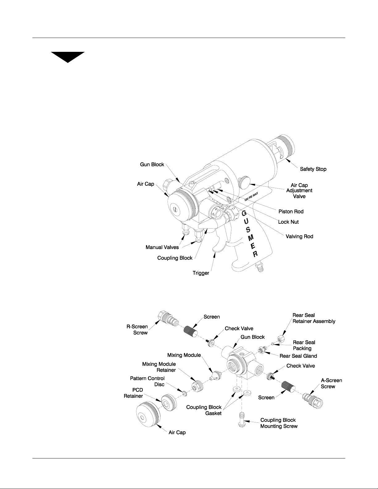
Major Components
In order to gain a thorough understanding of the GX-7-DI Spray Gun, please take time to
become familiar with its Major Components (See Figure 1) and its Centerline
Components (See Figure 2). This will be helpful later when these items are covered in
the manual.
Figure 1. Major Components
Figure 2. Centerline Components
10/3/01 7
Page 8
Gun Service Kits
NOTE:
For more information
concerning the 1-Quart Gun
Service Kit, consult the Parts
Identification Manual
(P/N OP205-ID).
Model GX-7-DI Spray Gun
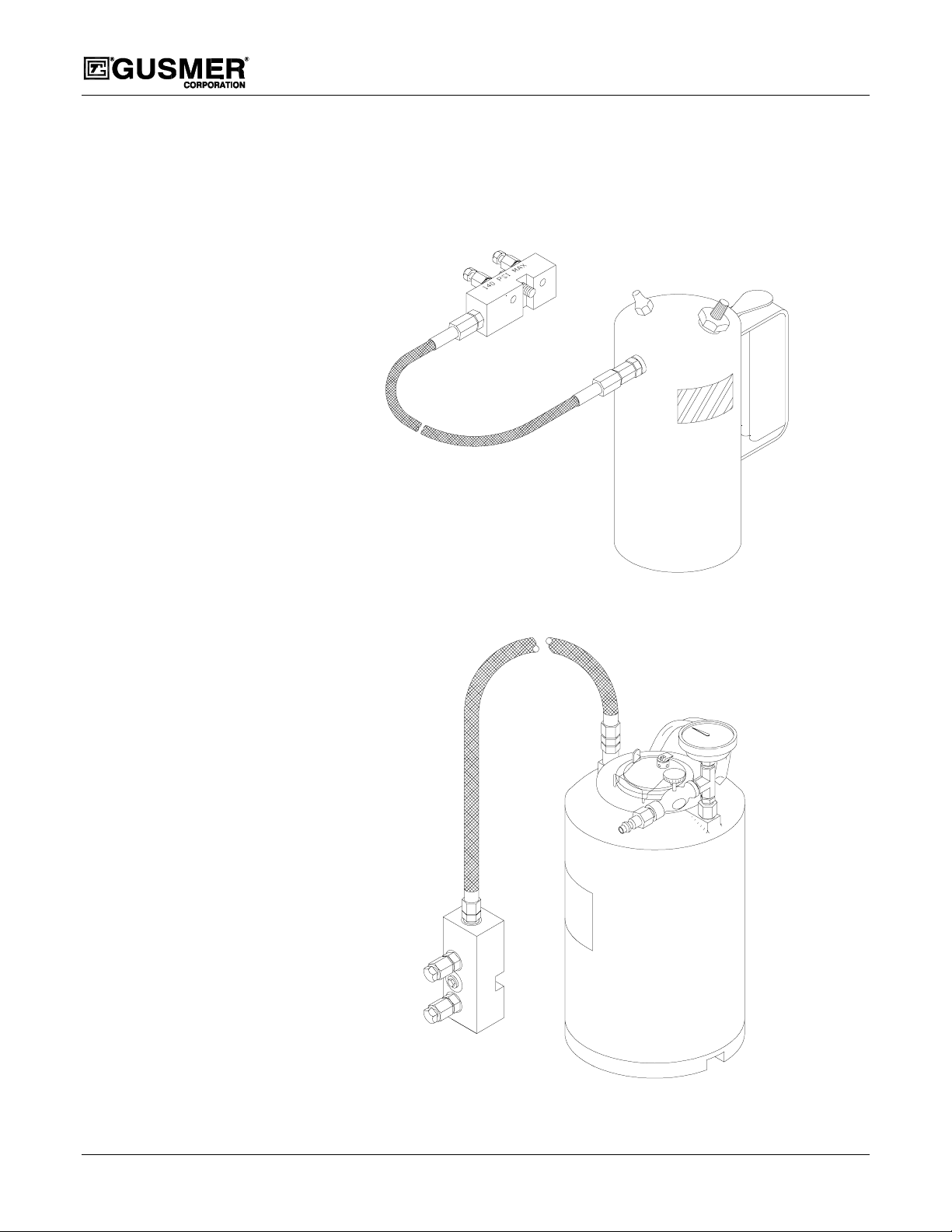
Cleaning the GX-7-DI Spray Gun with the 1-Quart Gun Service Kit (P/N OP205) or the
3-Gallon Gun Service Kit (P/N OP206) is essential to its proper operation. Both kits are
available separately.
NOTE:
For more information
concerning the
3-Gallon Gun Service Kit,
consult the Parts Identification
Manual
(P/N OP206-ID).
Figure 3. 1-Quart Gun Service Kit (P/N OP205)
Figure 4. 3-Gallon Gun Service Kit (P/N OP206)
8 22943-1, Issue 1
Page 9

Operating Manual Operation
OPERATION
WARNING: BODILY INJURY AND/OR PROPERTY DAMAGE MAYRESULTFROM ACCIDENTAL
OPERATION OF THE GUN.DONOTPOINT THE GUN AT OR NEAR OTHER PERSONNEL OR PLACE
ANY PART OF THE BODY IN THE PATH OF THE MATERIAL SPRAY
INTO THE DISPENSING END OF THE GUN
“CLOSED” SAFETY POSITION AND CLOSE BOTH MANUAL VALVES WHEN THE GUN IS NOT IN USE.
.ALWAYSENGAGE THE SAFETY STOP TO THE
Safety Position of Gun
The GX-7-DI Gun has a two position Safety Stop. When engaged, it prevents accidental
triggering of the gun during servicing or down time. When disengaged, it allows the gun
to dispense.
1. ENGAGE THE SAFETY STOP-
Push in and turn the Safety Stop
clockwise to place the gun in the
“Closed” safety position.
IMPORTANT: Always engage the
Safety Stop when the gun is not in use.
Figure 5. Safety Stop Closed
.DONOTAT ANY TIME LOOK
Position
Manual Valves
NOTE:
Unnecessary triggering of the
gun with the manual valves
closed may cause crossover if
there is any residual chemical
in the gun ports.
2. DISENGAGE THESAFETY STOP-
Push in and turn the Safety Stop counter
clockwise to place the gun in
the “Open” position. (The Red Band
will be exposed)
TOOLS REQUIRED
• 5/16” Spintite (P/N 0904A)
The Coupling Block is equipped with
Manual Valves that control the flow of each
chemical component to the gun.
1. OPEN BOTH MANUAL VALVESUsing the 5/16” Spintite, turn each
Manual Valve counter clockwise
approximately three full turns.
2. CLOSE BOTH MANUAL VALVESUsing the 5/16” Spintite, turn each
Manual Valve fully clockwise.
Red Band
Figure 6. Safety Stop Open Position
Coupling
Block
Manual Valves
Figure 7. Manual Valves
10/3/01 9
Page 10

IMPORTANT: To avoid accidental gun operation determine that the coupling b lock
manual valves have been closed before attempting to service the gun, or any time the
gun is not in use.
Air Line Configuration
TOOLS REQUIRED
• 3/16” Hex Key • 6” Adjustable Wrench
Model GX-7-DI Spray Gun
Figure 8. Air Line Configuration
The GX-7-DI air line connection can be configured in two different ways: The standard
configuration has the air connection at the base of the handle. The optional configuration
has the air connection at the rear of the gun. To change to the optional configuration
proceed as follows:
1. REMOVE THE 4“ LONG PIPE NIPPLE- Using the 6” Adjustable Wrench, remove
the 4“ long pipe nipple from the base of the Gun.
2. REMOVE THE 1/8” PIPE PLUG- Using the 3/16” Hex Key, remove the 1/8” pipe
plug from the rear of the gun.
3. INSTALL THE 1/8” PIPE PLUG- Using the 3/16” Hex Key, install the 1/8” pipe
plug in the location previouslyoccupied by the 4“ long pipe nipple.
4. INSTALL THE (OPTIONAL) SUPPLIED BRASS 1/8” NIPPLE- Using the 6”
Adjustable Wrench, install the supplied brass 1/8” nipple in the location previously
occupied by the 1/8” pipe plug.
IMPORTANT: If your gun was received with the Mixing Module and Pattern
Control Disc (PCD) installed, proceed to Start-Up. If your gun was received without
the Mixing Module and PCD installed, proceed to Mixing Module and PCD
Installation.
10 22943-1, Issue 1
Page 11

Operating Manual Operation
Mixing Module and PCD Installation
TOOLS REQUIRED
• 5/16” Spintite (P/N 0904A) • 3/8” Open-End Wrench
• 5/8” Open-End Wrench
NOTE:
Always lightly grease threads
that come into contact with
chemicals.
NOTE:
Tighten the PCD Retainer
finger tight only.
1. INSTALL THE MODULE- Without connecting the gun to the chemical hose,
connect the air supply to the gun. Move the safety to the “Open “ position. Holding
down the gun trigger, place the module over the tip of the valving rod. Align the
keying pin with the hole in the gun block and push in firmly. Install the module
retainer finger tight and release the trigger. Using the 5/8” Open-End Wrench,
tighten the retainer firmly (do not over tighten).
2. INST ALL THE PCD- Using the 3/8” Open-End Wrench, loosen the Rear Seal
Retainer Assembly slightly. Remove the Safety Stop from the gun. Using the 5/16”
Spintite and 3/8” Open-End Wrench, loosen the Locknut and screw the Valving Rod
rearward as far as it will go. Place the PCD over the Mixing Module Retainer.
Install the PCD Retainer and tighten by hand. With the gun in the closed position
(air supply connected), insert the 5/16” Spintite through the rear of the gun and
advance the Valving Rod forward to engage the PCD. When you feel the rod contact
the PCD, tighten another 1/10 of a turn. While holding the rod in position, tighten
the Locknut against the piston shaft until snug. Retighten the Rear Seal Retainer
Assembly.
3. CHECK ADJUSTMENT OF THE PCD- Hold down the gun trigger, loosen the PCD
Retainer, then release the trigger. Tighten the PCD Retainer and, while maintaining
the tightening torque, trigger the gun. The retainer should suddenly rotate
approximately 1/10 of a turn. Release the trigger. The adjustment is now complete.
Start-Up
TOOLS REQUIRED
• 5/16” Spintite (P/N 0904A)
IMPORTANT: Before attempting the following procedures, make sure the gun is
attached to the coupling block and air hoses, the proportioning unit is at the desired
temperature and pressure, and the system is ready for operation.
1. ADJUST THE AIR CAP ADJUSTMENT VALVE- The knurled knob on the left
side of the Air Cylinder controls the amount of air that passes over the PCD. This
flow of air helps keep the PCD free of sprayed chemical. Too much air can
adversely effect spray pattern shape and create undesirable amounts of over-spray.
However, the airflowcan be used to modify the spray pattern. Experiment to
determine what works best for the application.
Turn the knob Counter clockwise to open the valve and clockwise to close it.
2. OPEN BOTH MANUAL VALVES- Using the 5/16” Spintite, turn each valve
counter clockwise approximately three full turns.
3. DISENGAGE THE SAFETY STOP- Push in and turn the Safety Stop counter
clockwise to place the gun in the Open position (The Red Band will be exposed).
4. TEST SPRAY- Trigger the gun on a disposable surface and evaluate.
10/3/01 11
Page 12

Model GX-7-DI Spray Gun
Shutdown
TOOLS REQUIRED
• 5/16” Spintite
IMPORTANT: Follow this procedure whenever the gun is out of service for any
length of time. For mid/end of day service, see the Cleaning Procedure section of
this manual.
1. ENGAGE THE SAFETY STOP- Push in and turn the Safety Stop clockwise to place
the gun in the Closed safety position.
2. CLOSE BOTH MANUAL VALVES- Using the 5/16” Spintite, turn each valve fully
clockwise.
NOTE:
Disassembling the gun daily
for cleaning is not
recommended if it has been
operating properly. However,
if the gun is removed from the
hose, it should be flushed and
cleaned thoroughly.
3. CLEAN AS REQUIRED- See the Cleaning Procedure section of the manual.
IMPORTANT: As an additional safety precaution, the GX-7-DI air line has a quick
disconnect air coupling. Disconnect the air line when transporting the gun with the
chemical hoses connected.
12 22943-1, Issue 1
Page 13

Operating Manual Cleaning Procedure
CLEANING PROCEDURE
TOOLS REQUIRED
• 5/16” Spintite (P/N 0904A)
• 1-Quart Gun Service Kit (P/N OP205) or 3-Gallon Gun Service Kit (P/N
OP206)
• Flush Can (P/N 0919A)
The Gun Block must be thoroughly cleaned with Gun Cleaner before removing the
Valving Rod or mixing components from the Gun Block. In this way, the residue left
from the two components will be purged and diluted with Gun Cleaner and will not react
with one another when the Gun Block components are removed.
WARNING: PROPERLY GROUND ALL EQUIPMENT INVOLVED IN THE CLEANING OPERATION
TO AVOID STATIC SPARKING, WHICH COULD RESULT IN FIRE OR EXPLOSION.DONOTCLEAN
ON OR NEAR FOAMED OR COATED SURFACES
WARNING: WHEN SERVICING OR OPERATING THE GX-7-DI, SUFFICIENT PROTECTIVE
CLOTHING MUST BE WORN TO PREVENT PROLONGED SKIN CONTACT WITHTHE CHEMICALS OR
SOLVENTS USED IN OR WITH THE GUN
.
.
NOTE:
Opening one manual valve at a
time will allow flushing of
individual chemicals. This is
useful when flushing high
viscosity materials and
ensures maximum
effectiveness in purging the
gun of chemical.
LWAYS WEAR APPROVED SAFETY GLASSES OR GOGGLES,GLOVES, AND RESPIRATORY
A
EQUIPMENT WHEN SERVICING OR OPERATING THE
GX-7-DI.
1. ENGAGE THE SAFETY STOP- Push in and turn the Safety Stop clockwise to place
the gun in the Safety position.
2. CLOSE BOTH MANUAL VALVES- Using the 5/16” Spintite, turn each Manual
Valve fully clockwise.
3. REMOVE THE GUN FROM THE COUPLING BLOCK- Using the 5/16" Spintite,
remove the Coupling Block. Separate the gun from the Coupling Block. Using a rag
soaked with Gun Cleaner, wipe the face of the Coupling Block to prevent material
build-up.
4. ATTACH THE SERVICE BLOCK OF THE GUN SERVICE KIT TO THE GUN–
Using the 5/16” Spintite; fasten the Service Block to the gun. Pressurize the
container to 100 psi.
5. CLEAN THE GUN- Proceed as follows:
a) Open either one of the Manual Valves on the Service Block.
b) Disengage the Safety Stop by pushing in and turning counter clockwise
to place the gun in the Open position (The Red Band will be exposed).
c) Trigger the Gun Service Kit and the Gun simultaneously catching the
Gun Cleaner in an appropriate container.
(A fine, unobstructed mist of cleaner should exit the Tip.)
10/3/01 13
Page 14

Model GX-7-DI Spray Gun
d) Release both triggers and close the Manual Valves on the Service
Block.
e) Repeat the Procedure for the other side of the Gun.
f) After the initial cleaning, remove the Air Cap and PCD Retainer and
PCD and flush a second time. (This is done to get a more thorough
cleaning.)
6. REMOVE THE SERVICE BLOCK OF THE GUN SERVICE KIT FROM THE
GUN– Using the 5/16” Spintite; disconnect the Service Block from the gun.
7. CLEAN SCREENS, CHECK VALVES AND SCREEN SCREW- Using the Flush
Can, flush out the Screens, Check Valves and the Screen Screw Cavities completely
See the Screen Screw Removal and Service Procedure section of this manual.
Important: Inspect the Air Cap, PCD, Module, and Gun Block for build up of
material and clean them as required.
.
14 22943-1, Issue 1
Page 15

Operating Manual Servicing Procedures
SERVICING PROCEDURES
Screen Screw Removal And Service Procedure
TOOLS REQUIRED
• 5/8” Open-End Wrench
• 1/8” Dia. Clean Out Drill
• 21/64” Dia. Clean Out Drill
• Pin Vise W/Collets
• Flush Can
WARNING:
KIT PRIOR TO REMOVAL FOR SERVICING AS THEY ARE EXPOSEDTOTHE CHEMICAL.SEE THE
CLEANING PROCEDURE SECTION OF THIS MANUAL.
1. REMOVE THE SCREEN SCREW ASSEMBLY- Using the 5/8” Open-End Wrench,
unthread the Screen Screw from the Gun Block.
a) Remove the Check Valve from the Screen Screw. Clean the valve with Gun
b) Remove the Screen from the Screen Screw. If there are solid particles attached
2. CLEAN THE SCREEN SCREW CAVITY- Inspect the cavity. If any
visible remove them with a combination of the Clean Out Drills mentioned above and
Gun Cleaner.
WARNING:
WILL GO DIRECTLY INTO THE MODULE AND CLOG IT.
3. REINSTALL THE SCREEN SCREW ASSEMBLY- Reinstall the Screen and Check
Valve on the Screen Screw. Using the 5/8” Open-End Wrench, reinstall the Screen
Screw in the Gun Block. Make sure the screw is tight to ensure the integrity of this
metal-to-metal seal.
BE SURE TO FLUSH THE “CENTERLINE COMPONENTS” USING THE GUN SERVICE
Cleaner. Inspect for damage and replace if necessary.
to the Screen, try soaking it in Gun Cleaner. However, if the screen is especially
dirty and clogged, simply replace it.
particles are
ANY MATERIAL LEFT IN THE CAVITY ON THE DOWNSTREAM SIDE OF THE SCREEN
4. CLEAN THE GUN- Clean the gun after cleaning the Cavities and Screens. See the
Cleaning Procedure section of this manual. In this case, flush the gun with the
Mixing Module removed. This ensures that all particles are expelled from the gun
block and prevents blockage of the module ports.
10/3/01 15
Page 16

Centerline Component Removal
TOOLS REQUIRED
• 3/8” Open-End Wrench
• 5/8” Open-End Wrench
• 1/2” Open-End Wrench
• 3/16” HexKey
• 5/16” Spintite
• Lubriplate Grease
The Centerline Components consist of the following:
Model GX-7-DI Spray Gun
Figure 9. Centerline Component Removal
WARNING:
KIT PRIOR TO REMOVAL FOR SERVICING AS THEY ARE EXPOSEDTOTHE CHEMICAL.
1. ENGAGE THE SAFETY STOP- Push inand turn the Safety Stop clockwise to
place the gun in the Closed safety position.
2. CLOSE BOTH MANUAL VALVES- Using the 5/16” Spintite, turn each Manual
Valve fully clockwise.
3. REMOVE THE GUN FROM THE COUPLING BLOCK- Using the 5/16" Spintite,
remove the Coupling Block. Using a rag soaked with GunCleaner, wipe clean the
face of the Coupling Block to prevent material build-up.
4. REMOVE THE AIR CAP- Remove the Air Cap by hand by turning it counter
clockwise.
5. TRIGGER THE GUN- Trigger the gun and hold it. (Doing so retracts the Valving
Rod slightly and relieves pressure on the PCD Retainer.)
16 22943-1, Issue 1
BE SURE TO FLUSH THE “CENTERLINE COMPONENTS” WITH THE GUN SERVICE
Page 17

Operating Manual Servicing Procedures
6. REMOVE THE PCD RETAINER- Remove the PCD Retainer by hand by turning it
counter clockwise.
NOTE:
To free a PCD that appears to
be stuck, disengage the Safety
Stop, then depress and
release the gun trigger to
unseat it.
7. REMOVE THE PATTERN CONTROL DISC (PCD)- Lift the PCD off the Mixing
Module Retainer.
8. REMOVE THE MIXING MODULE RETAINER- Using the 5/8” Open-End
Wrench, remove the Mixing Module Retainer.
9. REMOVE THE MIXING MODULE- Move the Safety Stop to the “Open” position,
then depress and release the gun trigger. The Module should unseat itself from the
Gun Block. Lift the Module off the end of the Valving Rod.
Important: Do not attempt to dig out the Mixing Module using a sharp object.
10. LOOSEN T HE REAR SEAL RETAINER ASSEMBLY-Using the 1 /2” Open-End
Wrench, back out the Retainer Assembly one or two turns.
11. LOOSEN THE LOCK NUT- Using the 3/8” Open-End Wrench, loosen the Lock
Nut until it disengage s from the thread on the Valving Rod.
12. REMOVE THE SAFETY STOP- Push the Stop partially forward, rotate it to the full
counter clockwise position, and slide the Stop off the Air Cylinder.
13. REMOVE THE VALVING
ROD- Depress the Trigger
Lever and hold. Using a
3/8” Open-End Wrench,
hold the Lock Nut while
using the 5/16” Spintite to
unthread the Rod Draw Bar
and Valving Rod from the
rear of the gun. When the
threads disengage, remove
the assembly by hand.
Figure 10. Valving Rod Removal
14. DISCONNECT THE AIR SUPPLY- Disconnect the Air Hose from the Quick
Disconnect Fitting on the Air Supply Hose.
15. REMOVE THE GUN BLOCK-Using the 3/16” Hex Key, remove the Gun Block
Retaining Screw. Carefully slide the Gun Block awayfrom the Air Cylinder. If
dried chemical has built up on the Gun Block removal may be difficult. Removing
the dried chemical will make removal easier.
16. CLEAN ALL COMPONENTS THOROUGHLY BEFORE REASSEMBLY- Using
the appropriate Brass Brushes, Clean Out Drills, etc. remove residual chemical. Use
Cotton Swabs soaked with Gun Cleaner if necessary. When finished, coat the
threads and the mating surfaces
of the Gun Block, Gun Block Bracket, and Gun with
Lubriplate Grease.
17. INSPECT THE GUN BLOCK- It is important to keep the Gun Block clean and free
from damage to ensure proper operation of the Spray Gun. It has been coated with a
proprietary coating to help protect it from damage and make it more difficult for
chemical to adhere to it. However, it still requires periodic attention.
10/3/01 17
Page 18

Centerline Component Installation
TOOLS REQUIRED
• 3/8” Open-End Wrench
• 1/2” Open-End Wrench
• 5/8” Open-End Wrench
• 3/16” HexKey
• 5/16” Spintite
The Centerline Components consist of the following:
Model GX-7-DI Spray Gun
Figure 11. Centerline Component Installation
1. INSTALL THE VALVING ROD- Connect the Valving Rod to the Rod Draw Bar
and insert it into the Air Cylinder. Using the 5/16” Spintite, thread the assembly into
the End Cap until approximately 3/16” to 1/4” of thread is protruding from the end
of the Piston Rod.
2. INSTALL THE LOCK NUT- By hand, thread the Lock Nut on to the Valving Rod.
3. INSTALL THE GUN BLOCK- Carefullyslide the Gun Block onto the Valving Rod
towards the Air Cylinder. Using the 3/16” Hex Key, install the Gun Block onto the
Gun Block Mounting Bracket.
4. CONNECT THE AIR SUPPLY- Connect the Air Hose to the Quick Disconnect
Fitting on the Air Supply Hose.
5. INSTALL THE MIXING MODULE- Depress the Gun Trigger Lever and slide the
Mixing Module over the end of the Valving Rod while making sure its alignment pin
enters the alignment slot in the Gun Block. Keep the Gun Trigger Lever depressed
and proceed to Step 6.
18 22943-1, Issue 1
Page 19

Operating Manual Servicing Procedures
6. INSTALL THE MIXING MODULE RETAINER- With the Gun Trigger Lever
depressed, thread the Mixing Module Retainer in place by hand. Release the
Trigger. Using the 5/8” Open-End Wrench carefully tighten the Mixing Module
Retainer until it is “snug” to ensure no leaking will occur when pressurized chemical
is introduced in to the gun.
WARNING: O
BOTH THE MODULE AND THE GUN BLOCK.
7. INSTALL THE PATTERN CONTROL DISC (PCD)- Place the PCD over the end
of the Mixing Module Retainer.
8. INSTALL THE PCD RETAINER- By hand, thread the PCD Retainer onto the Gun
Block until snug.
9. ADJUST THE VALVING ROD- Follow Steps 5 through 9 in the Valving Rod
Adjustment section of this manual.
10. ADJUST THE PCD ORIENTATION- Using a 3/8”Open-End Wrench, rotate the
PCD clockwise to adjust the orientation of the PCD as required.
11. INSTALL THE AIR CAP- Thread the Air Cap in place by hand.
12. INSTALL THE SAFETY STOP- Slide the Stop onto the rear of the Air Cylinder.
Push the Stop partially forward and rotate it clockwise until it locks in the “Open”
position. (The Red Band will be exposed) Push the stop further forward and rotate it
clockwise until it locks in the “Closed” position.
VER TIGHTENING THE MIXING MODULE RETAINER WILL CAUSE DAMAGE TO
Valving Rod Adjustment
TOOLS REQUIRED
• 3/8” Open-End Wrench
• 1/2” Combination Wrench
• 5/16” Spintite
The GX-7-DI Valving Rod should not require adjustment if it was shipped from the
factory with the Mixing Module and PCD installed. The Valving Rod will require
adjusting in the following instances:
• Disassembly and servicing of the Air Cylinder
• Changing a Valving Rod
• Changing a Mixing Module
WARNING: DISCONNECT THE CHEMICAL HOSES AND AIR LINE BEFORE SERVICING THE GUN.
IN ADDITION, BE SURE TO FLUSH THE “CENTERLINE COMPONENTS” WITH THE GUN SERVICE
KIT PRIOR TO REMOVAL FOR SERVICING AS THEY ARE EXPOSEDTOTHE CHEMICAL.
10/3/01 19
Page 20

Model GX-7-DI Spray Gun
1. ENGAGE THE SAFETY STOP- Push inand turn the Safety Stop clockwise to
place the gun in the Closed safety position.
2. CLOSE BOTH MANUAL VALVES- Using the 5/16” Spintite, turn each Manual
Valve fully clockwise.
3. REMOVE THE GUN FROM THE HOSE- Using the 5/16" Spintite; remove the
Coupling Block Mounting Screw. Separate the gun from the Coupling Block. Using
a rag soaked with Gun Cleaner, wipe clean the face of the Coupling Block to prevent
material build-up.
4. PRESSURIZE THE AIR CYLINDER- After making sure that the Safety Stop is
engaged, connect the air line from the gun to the air source.
5. LOOSEN THE REAR SEAL RETAINER ASSEMBLY- Using the 1/2” Open-End
Wrench, back out the Retainer Assembly one or two turns. This will eliminate the
contact friction between the Seal, located inside the Packing Nut, and the Valving
Rod. With the packing loosened, the Valving Rod will move freely making the
adjustment procedure easier to perform.
6. LOOSEN THE LOCK NUT- Using the 3/8” Open-End Wrench, loosen the Lock
Nut by turning it counter clockwise. (As viewed from the front of the gun.)
Continue to back the Lock Nut away from the Valving Rod by three or four full
turns.
7. ADJUST VALVING ROD- Remove the Safety Stop from the gun. Using the 5/16”
Spintite through the rear of the gun, advance the Valving Rod forward to engage the
PCD. When you feel the Rod contact the PCD, tighten another 1/10 of a turn.
8. LOCK ADJUSTMENT IN PLACE- While carefully maintaining the position of the
Valving Rod, tighten the Lock Nut up against the Piston Rod.
9. RETIGHTEN THE REAR SEAL RETAINER ASSEMBLY- Using the 1/2” OpenEnd Wrench, retighten the Retainer Assembly.
20 22943-1, Issue 1
Page 21

Operating Manual Servicing Procedures
End Cap and Air Piston O-Ring and Cup Seal
Replacement
TOOLS REQUIRED
• Adjustable Wrench
• 1/2” Open-End Wrench
• 5/16” Spintite
• 9/64” Ball Point Hex Key
Figure 12. End Cap Assembly and Piston Assembly Removal
1. CLOSE BOTH MANUAL VALVES- Using the 5/16” Spintite, turn each Manual
Valve fully clockwise.
2. REMOVE THE GUN FROM THE COUPLING BLOCK- Using the 5/16" Spintite,
remove the Coupling Block. Using a rag soaked with GunCleaner, wipe clean the
face of the Coupling Block to prevent material build-up.
3. CLEAN THE GUN- See the Cleaning Procedure section of this manual.
WARNING: DISCONNECT THE AIR SUPPLY FROM THE GUN BEFORE PROCEEDING.BODILY
INJURY AND/OR PROPERTY DAMAGEMAY RESULT FROM ACCIDENTAL OPERATION OF THE GUN
WITH THE END CAP REMOVED
4. LOOSEN THE REAR SEAL RETAINER ASSEMBLY- Using the 1/2” Open-End
Wrench, back out the Retainer Assembly one or two turns.
10/3/01 21
.
Page 22

Model GX-7-DI Spray Gun
5. REMOVE THE SAFETY STOP- Push the Stop partially forward, rotate it to the full
counter clockwise position, and slide the Stop off the Air Cylinder.
6. REMOVE THE SOCKET HEAD SCREW AND CYLINDER CLAMP- Using the
9/64” Ball Point Hex Key, remove the rear #8 Socket Head Cap Screw and the
Cylinder Clamp fromthe Handle.
7. REMOVE THE END CAP- Using an Adjustable Wrench, remove the End Cap by
turning it counter clockwise from the Air Cylinder.
8. INSPECT THE END CAP O-RING- If necessaryreplace the O-Ring and install a
new one after lightly coating it with Lubriplate Grease.
9. INSPECT REAR CUP SEAL- Remove the Rear U Cup Seal from the End Cap and
inspect it for damage. Replace it if required, making sure that the “cup” is facing
towards the front of the air cylinder.
10. REMOVE THE PISTON ROD ASSEMBLY- By hand, pull the Piston Assemblyout
of the Air Cylinder. Inspect the O-Ring for damage and replace it if required. Apply
Lubriplate Grease to the newO-Ring and carefully install it, taking care not to
damage it.
11. REPLACE THE FRONT CUP SEAL- If air is escaping around the Piston Rod
during operation, remove and replace the Cup Seal located in the front of the air
cylinder. Lubricate the newcup seal and install it making sure that the “cup” is
facing towards the rear of the air cylinder.
12. INSTALL THE PISTON INTO THE AIR CYLINDER - Insert the Piston and Rod
Assembly into the Air cylinder. Be careful not to damage the cup seal in the front
face of the Air Cylinder as the rod passes through it.
13. INSTALL THE END CAP- Using an Adjustable Wrench, reinstall the end cap by
threading it clockwise into the air cylinder.
14. INSTALL THE SOCKET HEAD SCREW AND CYLINDER CLAMP- Using the
9/64” Ball Point Hex Key, retighten the #8 Socket Head Cap Screw and Cylinder
ClamptotheHandle.
15. INSTALL THE SAFETY STOP- Slide the Stop onto the rear of the Air Cylinder.
Push the Stop partially forward and rotate it clockwise until it locks in the “Open”
position. (The Red Band will be exposed) Push the stop further forward and rotate it
clockwise until it locks in the “Closed” position.
16. TIGHTEN THE REAR SEAL RETAINER ASSEMBLY- Use the 1/2” Open-End
Wrench to tighten the Retainer Assembly. Do not over tighten.
22 22943-1, Issue 1
Page 23
Operating Manual Servicing Procedures
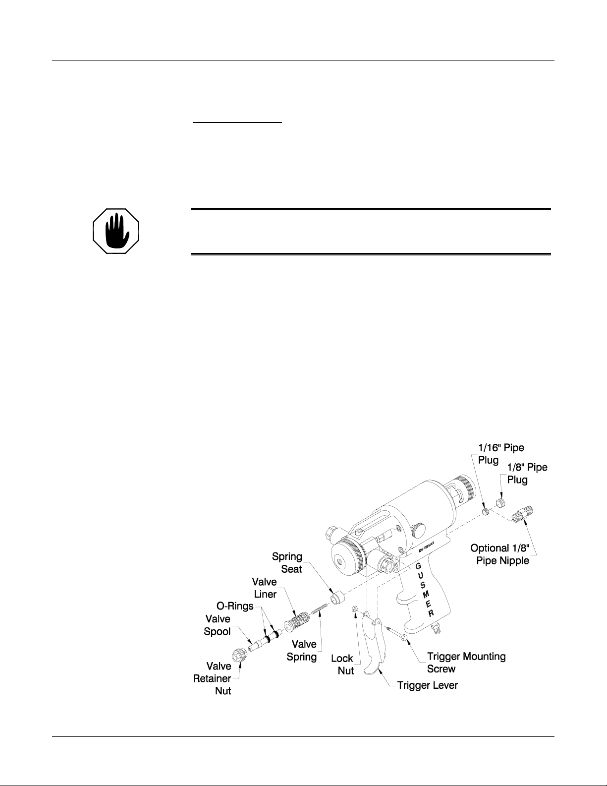
Trigger Valve O-Ring Replacement
TOOLS REQUIRED
• 5/32” HexKey • 3/8” x 5/16” Open-End Wrench
• 3/16” HexKey • PinPunchof¼”diameterorless
• 6” Adjustable Wrench • Ball Peen Hammer
• 6” Pliers
WARNING: D
IN ADDITION, BE SURE TO CLEAN THE “CENTERLINE COMPONENTS” WITH THE GUN SERVICE
KIT PRIOR TO REMOVAL FOR SERVICING AS THEY ARE EXPOSEDTOTHE CHEMICAL
1. CLOSE BOTH MANUAL VALVES- Using the 5/16” Spintite turn each Manual
Valve fully clockwise.
2. REMOVE THE GUN FROM THE COUPLING BLOCK- Using the 5/16" Spintite,
remove the Coupling Block Mounting Screw. Separate the gun from the Coupling
Block. Using a rag soaked with gun cleaner wipe clean the face of the Coupling
Block to prevent material build-up.
3. REMOVE THE TRIGGER LEVER- Using the 6” Adjustable Wrench and the 6”
Pliers remove the Screw and L ocknut that hold the Trigger Lever in place. Remove
the Trigger Lever.
4. REMOVE THE VALVE RETAINER NUT- Using the 3/8” end of the 3/8” x 5/16”
Open-End Wrench, remove the Valve Retainer Nut. This is the hex shaped nut that
surrounds the brass Spool Valve and holds it in p lace.
ISCONNECT THE CHEMICAL HOSES AND AIRLINE BEFORE SERVICINGTHE GUN.
Figure 13. Trigger/Air Valve Assembly
10/3/01 23
Page 24

Model GX-7-DI Spray Gun
NOTE:
RefertoFigure13forsteps5
through 16.
NOTE:
Follow Steps 6 through 14 to
replace the O-rings on the
Valve Liner. If they do not
need replacing go to step 15.
NOTE:
If the Gun is configured with
the air supply entering
through the rear of the Gun
Handle, as opposed to the
bottom of the Gun Handle,
remove the brass 1/8” Pipe
Nipple instead of the 1/8” Plug.
(See Figure 13)
5. REMOVE THE VALVE SPOOL- In order to replace the O-Rings located on the
Valve Spool, take hold of the end of the Spool and pull it out. Be careful extracting
the Spool as a spring will come out with it. Make sure not to lose this spring as it
belongs in the hole at the end of the Spool. Replace the O-Rings and apply a thin
coat of Lubriplate to the O-Rings.
6. REMOVE REAR 1/8” PLUG- In the rear of the Gun Handle locate the 1/8” Pipe
Plug. This plug seals one of the air flowpaths located internallyin the Gun Handle.
Using the 3/16” HexKey, remove the Plug.
7. REMOVE THE REAR INTERNAL 1/16” PIP E PLUG- Deeper in the hole that the
1/8” Plug was removed fromlocate the 1/16” Pipe Plug. This Plug seals yet another
airflow located internally in the Gun Handle. Remove that Plug using the 5/32” Hex
Key.
8. REMOVE THE SPRING SEAT- Looking into the hole from which both Plugs were
removed, the surface of the Spring Seat can be seen. Using a Pin Punch (¼”
diameter or less) and a hammer, gently tap the Spring Seat until both it and the Valve
Liner are pushed out the opposite end of the hole.
9. REMOVE & REPLACE THE O-RINGS- Remove and replace the four O-Rings on
the Liner. Apply a light coat of Lubriplate to the O-Rings.
10. CLEAN THE VALVE HOLE AND REMOVE ANY DEBRIS- Ensure the hole is
free of any dirt or debris and apply a thin coat of Lubriplate to the inside of the hole.
NOTE:
If the Gun is configured with
the air supply entering
through the rear of the Gun
Handle, reinstall the brass 1/8”
Pipe Nipple instead of the 1/8”
Plug. (See Figure 13)
11. REINSTALL THE SPRING SEAT- Slide the Spring Seat back into the Gun Handle
Air Valve hole, tapered end first, until it bottoms out in the hole.
12. REINSTALL THE VALVE LINER- Push the Valve Liner in as far as it will go (a
minimum of two or three internal threads should be visible). A fair amount of
resistance will be felt from interference between the O-rings and the inside diameter
of the hole. Install the Valve Retainer Nut, which when screwed in, will align the
Valve Liner and Spool to their proper depth.
13. REINSTALL THE 1/16” PLUG- Using the 5/32” Hex Key, screw the 1/16” Pipe
plug back in place. Apply a small amount of pipe thread sealant to the threads prior
to insertion. This will help seal the threads and prevent air leaks.
14. REINSTALL THE 1/8” PLUG- Apply a small amount of pipe thread sealant to the
threads of the Pipe Plug or Hex Nipple. Using the 3/13” Hex Key, reinsert the 1/8”
Pipe Plug.
15. REINSTALL THE VALVE SPOOL- Insert the Valve Spool, with the Valve Spool
Spring in place, into the Valve Liner. Screw in the Valve Retainer Nut. Be careful
not to over tighten it, just tighten until it is “snug”.
16. REASSEMBLE THE TRIGGER LEVER- Reinstall the Trigger Lever using the
Screw and Lock Nut. Tighten using the 6” Adjustable Wrench and the 6” Pliers.
24 22943-1, Issue 1
Page 25

Operating Manual Instruction Manual Discrepancy Report
INSTRUCTION MANUAL DISCREPANCY REPORT
Field
Number
1Date
2
3
4
5
6
7
Name
IM Number
Issue Number
Date of Issue
Page Number
Discrepancy
Field Title Description
Instructions:
Complete the above fields of the form by following the instructions listed on the reverse side of this sheet and mail to:
Gusmer Corporation
One Gusmer Drive PO Box 2055
Lakewood, NJ 08701
10/3/01 25
Page 26

Model GX-7-DI Spray Gun
Field
Number
1
2
3
4
5
6
7
Field Title Description
Date
Name
IM Number
Issue Number
Enter date report is submitted.
Enter name of person making report.
Enter the Part Number of the Instruction Manual from the title page.
Enter the Issue number of the Instruction Manual from the title page. If there is no
issue number, enter NONE.
Date of Issue
Enter the date of Issue of the Instruction Manual from the title page. If there is no
issue date, enter NONE.
Page Number
Discrepancy
Enter the page number containing the discrepancy.
Provide a brief description of discrepancy.
NOTE: You may send a marked copy of the page as an attachment to your
submittal.
26 22943-1, Issue 1
 Loading...