

Page 1
"Teamwork & Communication"
Model GAP
Spray Gun
Operating Manual
35943-1
December 6, 2000
Issue 5
GUSMER CORPORATION
A Subsidiaryof Gusmer MachineryGroup, Inc.
One Gusmer Drive
Lakewood, New Jersey, USA 08701-8055
Toll Free 1-800-367-4767 (USA & Canada)
Phone: (732) 370-9000
Fax: (732) 905-8968
Copyright 2000, GUSMER CORPORATION
http://www.gusmer.com
®
®
NOTICE: This manual contains important information for your GUSMER equipment. Read and retain for future reference.
Page 2

GAP Spray Gun
NOTICE:
The equipment described in this technical manual must only be operated or serviced by properly trained individuals,
thoroughly familiar with the operating instructions and limitations of the equipment. For technical service, call your local
distributor. Call: 1-800-FOR-GSMR (1-800-367-4767) for the name and telephone number of your local distributor.
NOTICE:
All statements, information and data given herein are believed to be accurate and reliable but are presented without guarantee,
warranty or responsibility of any kind expressed or implied. Statements or suggestions concerning possible use of GUSMER
equipment are made without representation or warranty that any such use is free of patent infringement, and are not
recommendations to infringe any patent. The user should not assume that all safety measures are indicated or that other
measures may not be required.
2 35943-1, Issue 5
Page 3

Operating Manual Contents
CONTENTS
LIST OF FIGURES..........................................................................................................4
WARRANTY ....................................................................................................................5
GENERAL SAFETY INFORMATION..........................................................................6
CCEPTABLEEQUIPMENT USES.......................................................................................6
A
O
PERATIONALSAFETY PROCEDURES...............................................................................7
MAJOR COMPONENTS................................................................................................8
OPERATION....................................................................................................................9
S
AFETY STOP OPERATION................................................................................................9
M
ANUAL VALVE OPERATION ..........................................................................................9
A
IR HOSE CONFIGURATIONS..........................................................................................10
I
NITIALSET UP PROCEDURE ..........................................................................................11
D
AILY START UP PROCEDURE .......................................................................................12
D
AILY SHUTDOWN PROCEDURE ....................................................................................12
D
AILY MAINTENANCE TEST PROCEDURE......................................................................13
SERVICING PROCEDURES........................................................................................14
IDE BLOCK SERVICE PROCEDURE ................................................................................14
S
M
IXING CHAMBER ANDGUN BLOCK SERVICE PROCEDURE..........................................16
E
ND CAP AND AIR PISTON O-RING SERVICEPROCEDURE .............................................17
E
ND CAP O-RING AND SAFETY STOP CUPSEAL SERVICE PROCEDURE..........................19
T
RIGGER VALVE O-RING PROCEDURE...........................................................................21
AIR PASSAGE DIAGRAMS.........................................................................................24
APPENDIX......................................................................................................................25
PECIFICATIONS.............................................................................................................25
S
NOTES.............................................................................................................................26
INSTRUCTION MANUAL DISCREPANCY REPORT............................................27
12/6/00 3
Page 4

GAP Spray Gun
LIST OF FIGURES
FIGURE 1. MAJOR COMPONENTS .......................................................................................8
F
IGURE 2. FRONT END COMPONENTS................................................................................8
F
IGURE 3. ENGAGE THE SAFETY STOP................................................................................9
F
IGURE 4. DISENGAGE THE SAFETY STOP ..........................................................................9
F
IGURE 5. MANUAL VALVES ..............................................................................................9
F
IGURE 6. AIR HOSE CONFIGURATION.............................................................................10
F
IGURE 7. SIDE BLOCK COMPONENT REMOVAL /INSTALLATION.......................................14
F
IGURE 8. TIGHTNING THE SIDE SEAL..............................................................................15
F
IGURE 9. SIDE SEAL INSPECTION ...................................................................................15
F
IGURE 10. MIXING CHAMBER AND GUN BLOCK REMOVAL/INSTALLATION ........................16
F
IGURE 11. END CAP AND PISTON ASSEMBLY ...................................................................18
F
IGURE 12. PISTON ASSEMBLY..........................................................................................18
F
IGURE 13. END CAP ASSEMBLY.......................................................................................20
F
IGURE 14. SAFETY STOP ASSEMBLY.................................................................................20
F
IGURE 15. TRIGGER/AIR VALVE ASSEMBLY......................................................................22
F
IGURE 16. AIR CYLINDER AIR PASSAGES .........................................................................24
F
IGURE 17. HANDLE AIR PASSAGES..................................................................................24
4 35943-1, Issue 5
Page 5

Operating Manual Warranty
WARRANTY
Gusmer Corporation (Gusmer) provides a limited warranty to the original purchaser (Customer) of
Gusmer manufactured parts and equipment (Product) against any defects in material or
workmanship for a period of one year from the date of shipment from Gusmer facilities.
In the event Product is suspected to be defective in material or workmanship, it must be returned to
Gusmer, freight prepaid. If Product is found to be defective in material or workmanship, as
determined solely by Gusmer, Gusmer will issue full credit to Customer for the freight charges
incurred in returning the defective Product, and either credit will be issued for the replacement cost
of the Product or a replacement part will be forwarded no-charge, freight prepaid to Customer.
This w arranty shall not apply to Product Gusmer finds to be defective resulting from: installation,
use, maintenance, or procedures not accomplished in accordance with our instructions; normal
wear; accident; negligence; alterations not authorized in writing by Gusmer; use of “look alike”
parts not manufactured or supplied by Gusmer; or Product used in conjunction with any other
manufacturer's pumping or proportioning equipment. Further, the terms and conditions of this
warranty shall not apply to services or repairs made to Product by any third party not authorized in
writing by Gusmer. For such Product, a written estimate will be submitted to Customer at a
nominal service charge, itemizing the cost for repair. Disposition of Product will be done in
accordance withthe terms stated on the written estimate.
The warranty provisions applied to product that are not manufactured by Gusmer will be solely in
accordance with the warrantyprovided by the original manufacturer of the product.
GUSMER MAKES NO WARRANTY WHATSOEVER AS TO THE MERCHANTABILITY OF,
OR SUITABILITY FOR, ITS PRODUCT TO PERFORM ANY PARTICULAR PURPOSE.
CREDIT FOR, OR REPLACEMENT OF, PRODUCT DEFECTIVE IN MATERIAL OR
WORKMANSHI P SHALL CONSTITUTE COMPLETE FULFILLMENT OF GUSMER
OBLIGATIONS TO CUSTOMER. NO OTHER WARRANTY, EXPRESSED OR IMPLIED O N
ANY PRODUCT IT MANUFACTURES AND/OR SELLS, WILL BE RECOGNIZED BY
GUSMER UNLESS SAID WARRANTY IS IN WRITING AND APPR OVED BY AN OFFICER
OF GUSMER.
Under no circumstances shall Gusmer be liable for loss of prospective or speculative profits, or
special indirect, incidental or consequential damages. Further, Gusmer shall have no liability for
any expenses including, but not limited to personal injuryor property damage resulting from failure
of performance of the product, use of the product, or application of the material dispensed through
the product. Any information provided by Gusmer that is based on data received from a third
source, or that pertains to product not manufactured by Gusmer, while believed to be accurate and
reliable, is presented without guarantee, warranty, or responsibility of any kind, expressed or
implied.
Gusmer through the sale, lease, or rental of Productin no way expresses or implies a license for the
use of, nor encourages the infringement of any patents or licenses.
To insure proper validation of your warranty, please complete the warranty card and return it to
Gusmer withintwo weeks ofreceipt of equipment.
Revised 11/12/98
12/6/00 5
Page 6

GAP Spray Gun
GENERAL SAFETY INFORMATION
It is necessary to understand and follow the instructions in this manual to insure proper
and safe operation of the equipment.
As with most mechanical equipment, certain safety precautions must be taken when the
equipment discussed in this manual is operated or serviced. Severe bodily injury or
damage to equipment and property mayresult if the instructions and precautions listed
throughout this manual are not followed.
Needless to say, sufficient guidelines cannot be developed to eliminate the need for good
common sense in the use and servicing of this equipment, and in the use and application
of the products, this equipment has been designed to process. Users of this equipment
must therefore, make their own determination as to the suitability of the information
contained in this manual to their specific operation and requirements. There should be no
assumption made that the safety measures and instructions contained herein are allinclusive, and that other safety measures may not be required for specific use or
application.
The following safety guidelines are generallyapplicable to the safe and efficient use of
the equipment.
Acceptable Equipment Uses
The design of this equipment allows the dispensing of polyurethan e foams, twocomponent coating systems, polyureas, and some adhesives. Under no circumstances
should any acid or corrosive chemicals be used in the unit. Consult GUSMER if there is
any doubt about the compatibility of the chemical system to be used with this equipment.
Any use of this equipment other than as indicated above constitutes misuse unless express
written approval is obtained from GUSMER.
6 35943-1, Issue 5
Page 7
Operating Manual General Safety Information
Operational Safety Procedures
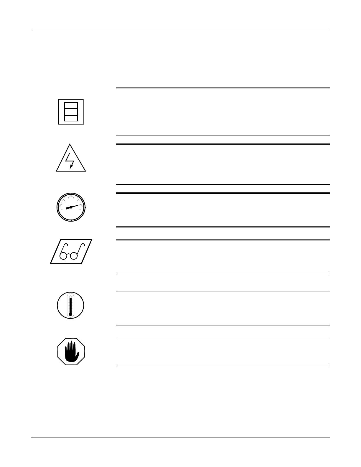
This safety information is not repeated in this manual. The symbols pertaining to this
information will appear where appropriate to alert the operator to potential hazards.
Solvents and Chemicals
High Voltage
High Pressure
Personal Protective
Equipment
WARNING: T
OPERATOR TO CERTAIN HAZARDS.ADEQUATE PERSONAL PROTECTIVE MEASURES MUST BE
TAKEN SO AS TO AVOID EXCEEDING THE
BEING USED
HE SOLVENTS AND CHEMICALS USED WITH THIS EQUIPMENT EXPOSE THE
THRESHOLD LIMIT VALUE (TLV) OF THE PRODUCTS
, AS ESTABLISHED BY THE OCCUPATIONAL SAFETY ANDHEALTHADMINISTRATION
(OSHA) OR OTHER QUALIFIED AGENCY.INFORMATION CONCERNING PERSONAL PROTECTION
AND PROPER HANDLING SHOULD BE OBTAINED FROM THE SUPPLIER OF SUCH CHEMICALS
WARNING: T
THE ELECTRIC CONSOLES OR OTHERWISE SERVICE THIS EQUIPMENT AND/OR EQUIPMENT USED
WITH IT BEFORE SWITCHING OFF THE MAIN POWER DISCONNECT AND INTERRUPTINGSUPPLY
VOLTAGE AT THE SOURCE
A QUALIFIED ELECTRICIAN
WARNING:T
COMPONENTS CAPABLE OF PRODUCING UP TO 3500 PSI.TO AVOID SERIOUS BODILYINJURY
FROM HYDRAULIC INJECTION OF FLUID
SERVICE HYDRAULIC COMPONENTS WITHOUT BLEEDING ALL PRESSURES TO ZERO
WARNING: T
WHEN OPERATING, SERVICING, ORBEINGPRESENT IN THE OPERATIONAL ZONE OF THIS
EQUIPMENT
SAFETY SHOES, AND RESPIRATORY EQUIPMENT AS REQUIRED.
O PREVENT SERIOUS BODILY INJURYFROMELECTRICALSHOCK, NEVER OPEN
.THE ELECTRICAL SERVICE MUST BE INSTALLED AND MAINTAINED BY
.
HIS EQUIPMENT HAS OR IS USED WITH EQUIPMENT THAT HAS HYDRAULIC
, NEVER OPEN ANY HYDRAULIC CONNECTIONS OR
.
O AVOID SERIOUS BODILY INJURY, PROPER PROTECTIVE GEAR MUST BE WORN
.THIS INCLUDES, BUT IS NOT LIMITED TO, EYE AND FACE PROTECTION, GLOVES,
.
WARNING: T
TEMPERATURE COMPONENTS SUCH AS PRIMARY HEATERS AND HEATED HOSES.TO PREVENT
SERIOUS BODILY INJURY FROM HOT FLUID OR HOTMETAL
EQUIPMENT BEFORE ALLOWING IT TO COOL
HIS EQUIPMENT HAS OR IS USED WITH EQUIPMENT THAT HAS HIGH
, NEVER ATTEMPT TO SERVICE THE
.
High Temperature
WARNING:F
PERSONAL INJURY AND/OR DAMAGE TO THE EQUIPMENT FROM ONE OR MORE OF THE ABOVE
LISTED HAZARDS
AILURE TO READ AND FOLLOW THIS SAFETY INFORMATION MAY RESULT IN
Warning
12/6/00 7
Page 8
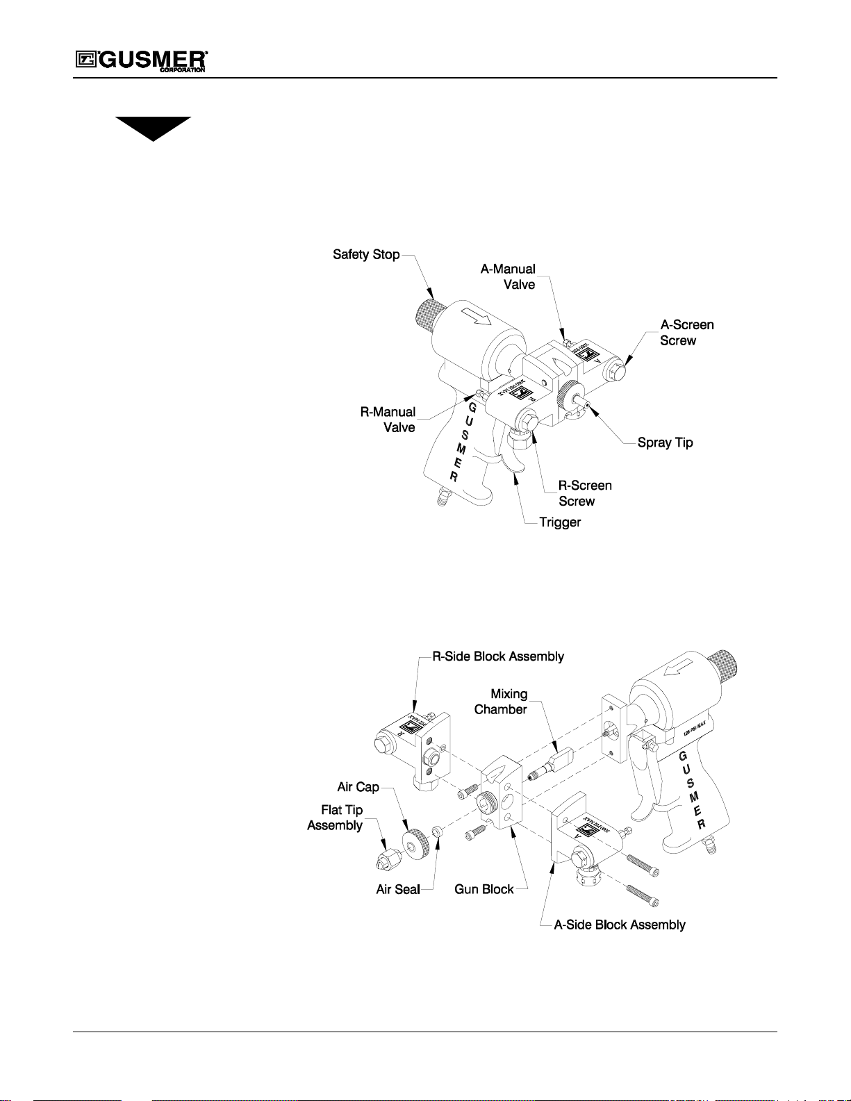
MAJOR COMPONENTS
In keeping with the need to gain a complete and thorough understanding of the
equipment, please take time to become familiar with the major components of the
GAP (Gusmer Air Purge) Gun and its Front End Components.
GAP Spray Gun
NOTE:
For a detailed account of
the components shown in
Figure 1 and Figure 2,
consult the GAP Spray Gun
Parts Identification Manual
(P/N 35943-ID).
Figure 1. Major Components
(Gun shown with Round Spray Tip)
Figure 2. Front End Components
(GunshownwithFlatSprayTipAssembly)
8 35943-1, Issue 5
Page 9
Operating Manual Operation
OPERATION
WARNING: NEVER POINT THE GUN AT OR NEAR OTHER PERSONNEL OR PLACE ANY PART OF
THE BODY IN THE PATH OF THE MATERIAL SPRAY.DO NOT LOOK INTO THE DISPENSING END OF
THE GUN
USING THE GUN
DAMAGE FROM THE ACCIDENTAL OPERATION OF THEGUN
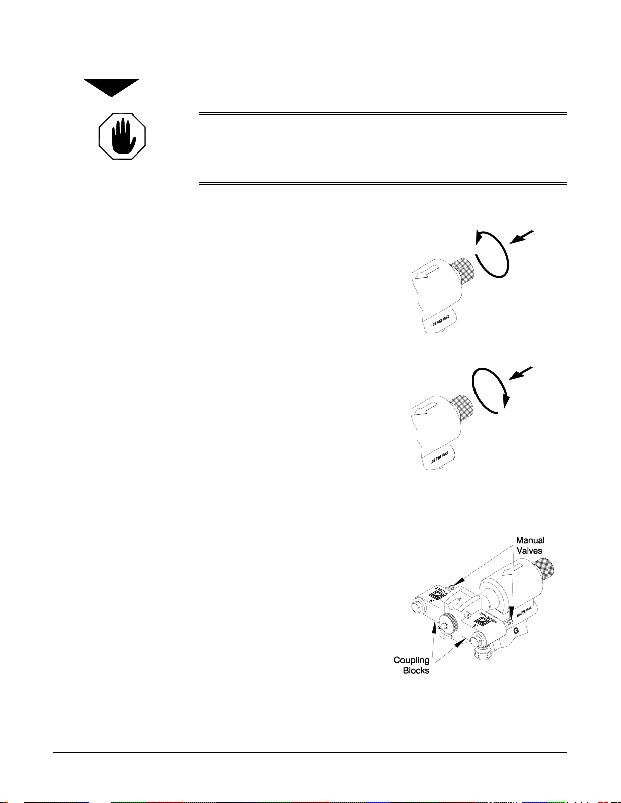
Safety Stop Operation
The GAP Gun has a two position Safety
Stop. When engaged, it prevents
accidental triggering of the gun during
servicing or down time. When
disengaged, it allows the gun to dispense.
1. ENGAGE THE SAFETY STOP-
.ALWAYS ENGAGE THE SAFETY STOP AND CLOSE BOTH MANUAL VALVES WHEN NOT
.DO THIS TO AVOID THE POSSIBILITY OF BODILY INJURYOR PROPERTY
.
Push in and turn the Safety Stop knob
clockwise to place the gun in the
Safety detented position.
Figure 3. Engage the Safety Stop
Manual Valve Operation
NOTE:
Triggering of the gun with the
manual valves closed may
cause crossover if there is any
residual chemical in the gun
ports.
IMPORTANT: Always engage the
Safety Stop when the gun is not in use.
2. DISENGAGE THESAFETY
STOP- Push in and turn the Safety
Stop knob counterclockwise to place
the gun in the Open detented position.
TheGAPGunSideBlockshaveManual
Valves that control the flowof each
chemical component to the gun.
1. OPEN BOTH MANUAL
VALVES- Using a 5/16” Spintite,
turn each Manual Valve at least three
full turns counterclockwise.
2. CLOSE BOTH MANUAL
VALVES- Using a 5/16” Spintite,
turn each Manual Valve fully
clockwise.
Figure 4. Disengage the Safety Stop
Figure 5. Manual Valves
IMPORTANT: Topreventaccidental gun operation, always engage the Safety Stop and
close both Manual Valves before att empti ng to service the gun or l eaveit unattended.
12/6/00 9
Page 10
GAP Spray Gun
Air Hose Configurations
TOOLS REQUIRED
• 3/16” Hex Key
• (2) 6” Adjustable Wrench
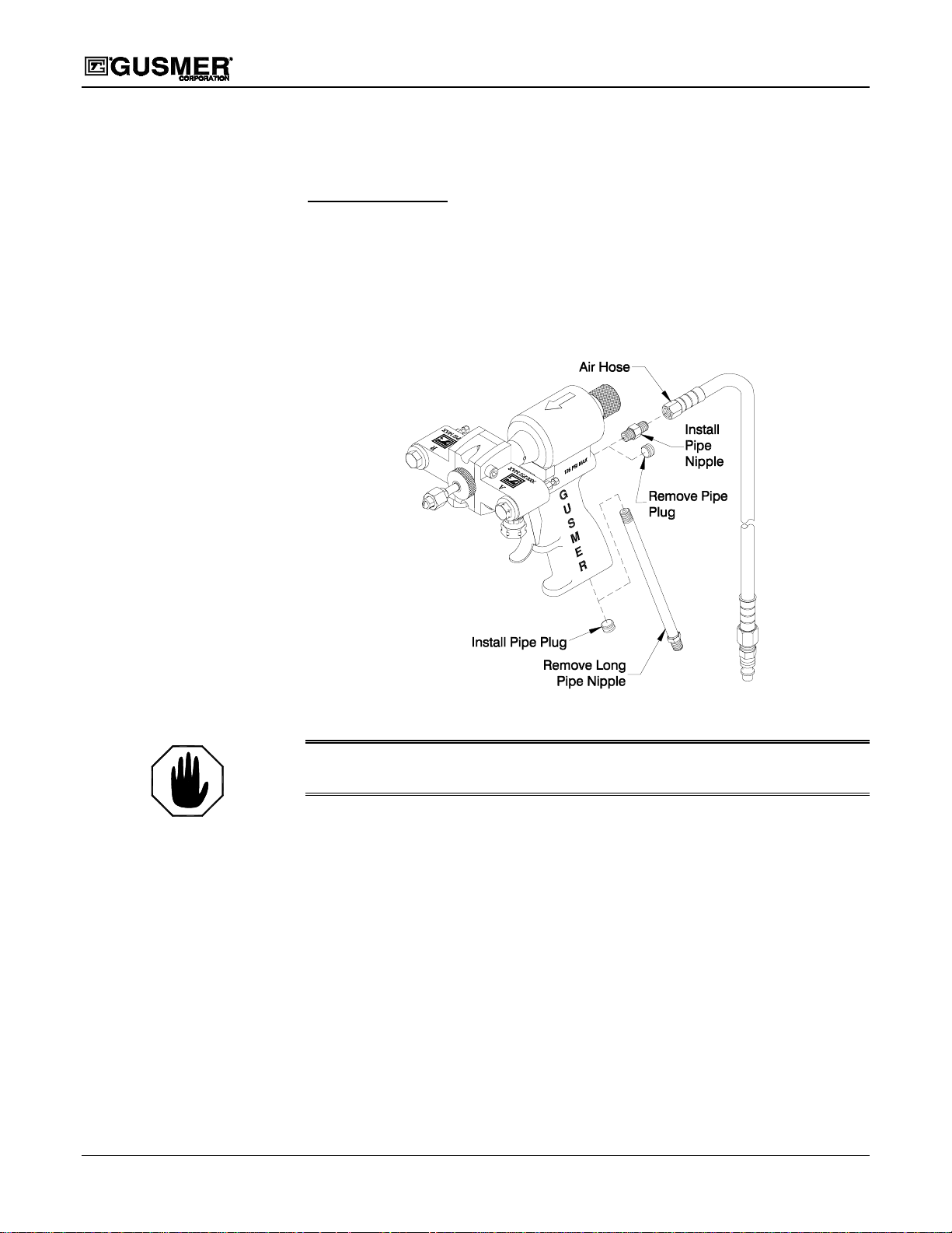
The GAP Gun design allows for two different Air Hose configurations. The standard
configuration has the air connection at the base of the handle. The optional configuration
has the air connection at the rear of the gun. To change to the optional configuration
proceed as follows:
Figure 6. Air Hose Configuration
WARNING:B
ENGAGE THE SAFETY STOP, AND DISCONNECTTHE AIR FROM THE GUN.
1. REMOVE THE AIR HOSE- Using a 6” Adjustable Wrench remove the Air Hose
from the Long Pipe Nipple at the base of the gun handle.
2. REMO VE THE LONG PIPE NIPPLE- Using a 6” Adjustable Wrench, remove
the Long Pipe Nipple from the base of the gun handle.
3. REMOVE THE PIPE PLUG- Using the 3/16” Hex Key, remove the Pipe Plug
from the back of the gun.
4. INSTALL THE PIPE PLUG- Using the 3/16” Hex Key, install the Pipe Plug in the
base of the gun handle in the hole previously occupied bythe Air Hose.
5. INSTALL THE PIPE NIPPLE (Supplied with Gun)- Using a 6” Adjustable
Wrench, install the Pipe Nipple in the back of the gun.
6. INSTALL THE AIR HOSE- Using a 6” Adjustable Wrench, connect the Air Hose
to the Pipe Nipple at the back of the gun.
10 35943-1, Issue 5
EFORE ATTEMPTING THIS PROCEDURE, CLOSE BOTH MANUAL VALVES,
Page 11

Operating Manual Operation
Initial Set Up Procedure
TOOLS REQUIRED
• 5/16” Spintite • Clean Rag
• (2) 6” Adjustable Wrench • Gun Cleaner
• 5/32” Hex Key • (2) Clean Container
1. CLOSE BOTH MANUAL VALVES- Using the 5/16” Spintite, turn each valve
fully clockwise.
2. ENGAGE THE SAFETY STOP- Push in and turn the Safety Stop knob clockwise
to place the gun in the Safety detented position.
3. INSTALL THE FEMALE QUICK DISCONNECT FITTING- Using two 6”
Adjustable Wrenches install the Female Quick Disconnect Fitting on to the Air
Supply Hose which is bundled withthe Chemical Supply Hoses.
NOTE:
The A (Isocyanate) and R
(Resin) hose connection
thread sizes are different,
making it virtually impossible
to improperly connect the
hoses. The, A (Isocyanate)
thread is 1/2-20, whereas the R
(Resin) thread is 9/16-18.
4. CONNECT THE CHEMICAL HOSES- Using two 6” Adjustable Wrenches
connect the Aand R Chemical Hosesto the corresponding A and R Side Blocks.
5. PRESSURIZE THE CHEMICAL HOSES- Pressurize the A and R Chemical
Hoses and check for leaks.
6. REMOVE THE GUN FROM THE SIDE BLOCKS- Using the 5/32” Hex Key,
remove the Side Block Mounting Screws. Carefully separate each Side Block from
the Gun Block.
7. BLEED AIR FROM THE CHEMICAL HOSES- Proceed as follows:
a) Hold each Side Block over a separate container.
b) Open each Manual Valve with the 5/16” Spintite to allowany trapped air to
escape. Bleed each side for a short time and alternate back and forth to maintain
an even pressure balance until the chemical leaving the hoses is free of air.
c) Close both Manual Valves.
8. CLEAN THESIDE BLOCKS- Wipe each Side Block and its mating surfaces clean
of any chemical using a rag soaked in gun cleaner.
WARNING: D
WILL PROMOTE THE COLLECTION OF DIRT CAUSING PREMATURE WEAR OF THE SIDE SEAL AND
O NOT APPLY ANY GREASE TO THE MATINGSURFACES OF SIDEBLOCK AS IT
MIXING MODULE.
9. REINSTALL THE SIDEBLOCKS ON TH E GUN BLOCK- Using the 5/32”
Hex Key secure the A and R Side Blocks to the Gun Block with the two socket head
cap screws. Make sure to sufficiently tighten the screws equally to prevent leakage.
10. CHECK THE PROPORTIONINGUNIT- Check the Proportioning Unit for
proper hose temperature, heater temperature, and pressure.
12/6/00 11
Page 12

GAP Spray Gun
11. CONNECT THE AIR SUPPLY- Connect the Air Hose to the Quick Disconnect
Fitting on the Air Supply Hose.
12. OPEN BOTH MANUAL VALVES- Using a 5/16” Spintite, turn each Manual
Valve at least three
13. DISENGAGE THE SAFETY STOP- Push in and turn the Safety Stop knob
counterclockwise to place the gun in the Open detented position.
14. TEST SPRAY OFF TARGET-
full turns counterclockwise.
Daily Start Up Procedure
TOOLS REQUIRED
• 5/16” Spintite
IMPORTANT: Before attempting the following procedures, make sure the Side
Blocks are properly attached to the gun, the proportioning unit is at the desired
temperature and pressure, and the system is ready for operation.
1. CONNECT THE AIR SUPPLY- Connect the Air Hose to the Quick Disconnect
Fitting on the Air Supply Hose.
2. OPEN BOTH MANUAL VALVES- Using a 5/16” Spintite, turn each Manual
Valve at least three
3. DISENGAGE THESAFETY STOP- Push in and turn the Safety Stop Knob
counterclockwise to place the gun in the Open detented position.
4. TEST SPRAY OFF TARGET-
full turns counterclockwise.
Daily Shutdown Procedure
TOOLS REQUIRED
• 5/16” Spintite
IMPORTANT: Follow this procedure whenever the gun is out of service for any
length of time.
1. CLOSE BOTH MANUAL VALVES- Using the 5/16” Spintite, turn each valve
fully clockwise.
2. ENGAGE THE SAFETY STOP- Push in and turn the Safety Stop knob clockwise
to place the gun in the Safety detented position.
3. DISCONNECT THE AIR SUPPLY- Disconnect the Air Hose from the Quick
Disconnect Fitting on the Air Supply Hose.
Proceed to the Daily Maintenance Test Procedure o n page 13.
12 35943-1, Issue 5
Page 13

Operating Manual Operation
Daily Maintenance Test Procedure
TOOLS REQUIRED
• 5/16” Spintite
IMPORTANT: This procedure checks for chemical leaks caused by a damaged
Mixing Chamber and/or Side Block Seal(s). Perform it at the end of the day on a
daily basis after completing the Daily Shutdown Procedure.
1. OPEN BOTH MANUAL VALVES- Using a 5/16” Spintite, turn each Manual
Valve at least three
2. CONNECT AND DISCONNECT THE AIR SUPPLY- Connect the Quick
Disconnect Fitting to the Air Supply Hose and then disconnect it. Wait
approximately 10 to 20 seconds and then reconnect the Quick Disconnect Fitting to
the Air Supply Hose.
Repeat this procedure two or three times.
3. CHECK FOR LEAKAGE- Check for material purging from the tip of the gun. If
there is, check the Mixing Chamber and Side Block Seals for damage.
full turns counterclockwise.
• For Mixing Chamber maintenance see the Mixing Chamber and Gun Block
Service Procedure on page 16.
• For Side Block Seal maintenance see the Side Block Service Procedure on
page 14.
4. CLEAN AS REQUIRED- See the Servicing Procedures section of this manual on
Page 14.
12/6/00 13
Page 14
SERVICING PROCEDURES
Side Block Service Procedure
NOTE:
Consult the GAP Spray Gun
Parts Identification Manual
(P/N 35943-ID) for specific
Part Numbers.
GAP Spray Gun
TOOLS REQUIRED
• 5/16” Spintite • Cotton Swabs
• 5/32” Hex Key • Clean Out Drills
• 6” Adjustable Wrench • Gun Cleaner
• 1/2” Wrench • Brass Brushes
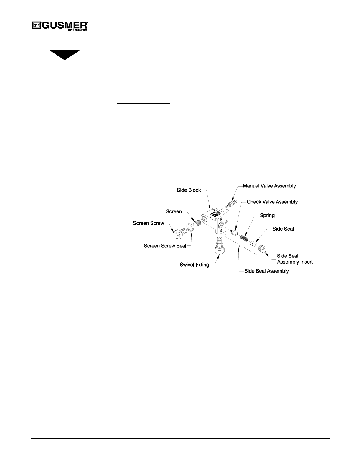
The Side Block Components consist of the following:
Figure 7. Side Block Component Removal / Installation
( R-Side Block shown )
1. PERFORM SHUTDOWN PROCEDURE- See the Daily Shutdown Procedure on
Page 12.
2. INSPECT THE SCREEN SCREW ASSEMBLIES- Using the 6” Adjustable
Wrench remove the A- Side Block Screen Assembly. Inspect the Screen Screw Seal
for damage. Thoroughly rinse the Screen and dry. Inspect the Screen by holding it
up to a bright light. The Screen mesh should be free of particles and varnish buildup. Replace as required. Repeat steps for R- Side Block Screen Assembly.
3. REMOVE THE GUN FROM THE SIDE BLOCKS- Using the 5/32” Hex Key,
remove the Side Block Mounting Screws. Carefully separate each Side Block from
the Gun Block. If this proves difficult, try removing any dried chemical that may
have accumulated. Wipe mating surfaces clean with a r ag soaked in gun cleaner.
4. REMOVETHESIDESEALASSEMBLY-Using the 1/2” Wrench, remove the
Side Seal Assembly from the Side Block.
14 35943-1, Issue 5
Page 15
Operating Manual Servicing Procedures
5. CLEAN AND INSPECT THE SIDE SEAL ASSEMBLY COMPONENTS–
Remove the Check Valve from the Side Seal Assembly. Clean the valve with gun
cleaner. Inspect, and replace if damaged. Remove the Side Block Seal from the Side
Seal Assembly Insert. Inspect it, and replace if damaged. Reassemble the Seal
Assembly.
WARNING: DO NOT CLEAN THE PLASTIC SIDE BLOCK SEAL(S) WITHA POCKETKNIFE, RAZOR
BLADE, BRASS BRUSH, OR ANY OTHER TOOLWHICH COULD MAR OR SCRATCH THE SUFRACE.
U
SE A WOODEN OR PLASTIC SCRAPER TOOL INSTEAD.
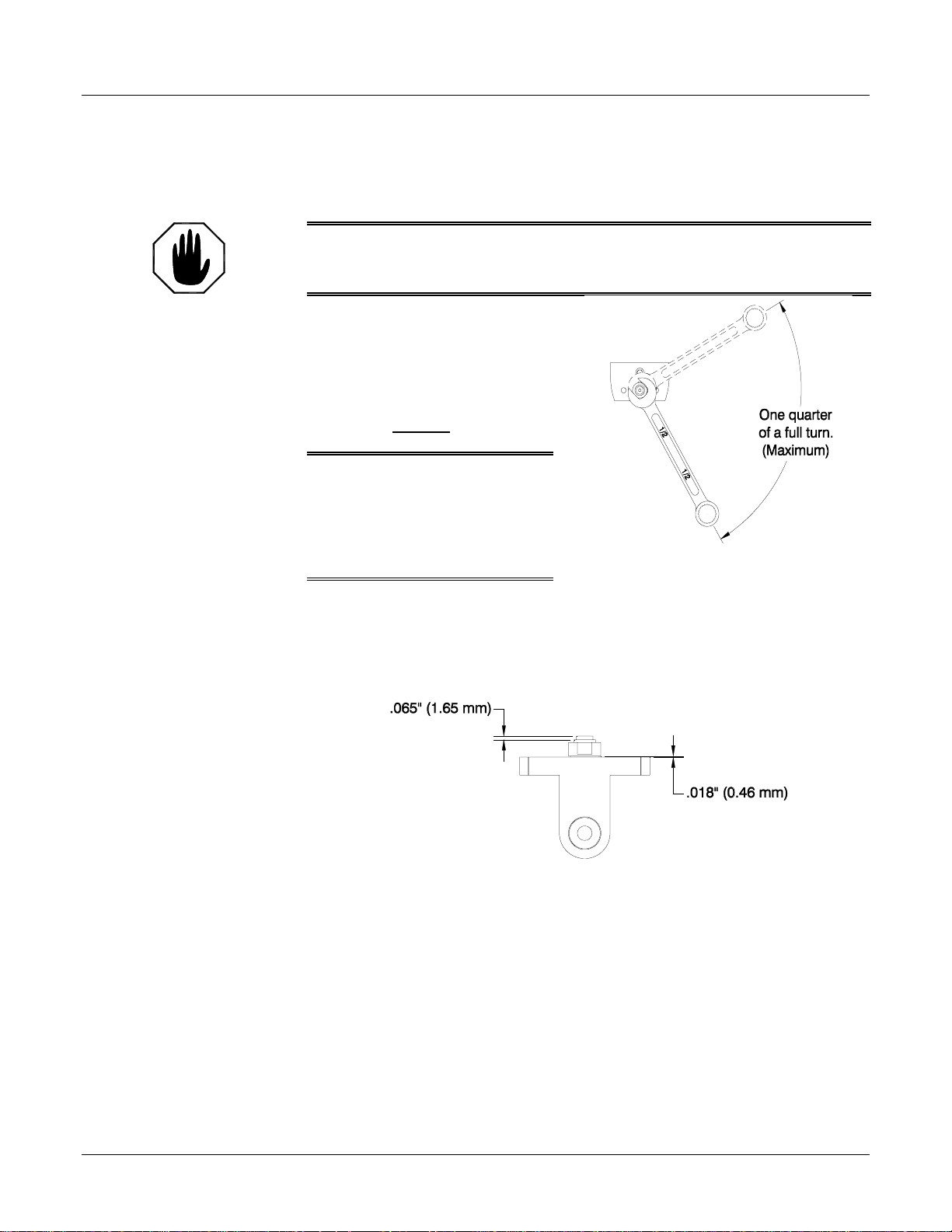
6. REINSTALL THE SIDE SEAL
ASSEMBLY- Thread the Side
Seal Assembly into the Side
Block by hand. Using a 1/2”
Wrench tighten the Side Seal
Assemblyby one quarter of a full
turn and No More
.
WARNING: TIGHTENING ANY MORE
THAN ONE QUARTER OF A FULL TURN
WILL CRUSH AND DAMAGE THE SIDE
SEAL ASSEMBLY AND MAY CAUSE
LEAKAGE WHEN THE GUN IS
PRESSURIZED
.
Figure 8. Tightning the Side Seal
NOTE:
RepeatSteps4,5,6,and7for
the opposite Side Block and
proceed to Step 8.
7. INSPECT THE SIDE SEAL ASSEMBLY FOR WEARAND DAMAGE–
a) Inspect the Side Seal for wear by measuring how far the seal protrudes from the
Side Seal Assembly Insert. A worn Side Seal will promote chemical leakage.
Replace the Side Seal if it protrudes .065” (1.65 mm) or less.
Figure 9. Side Seal Inspection
b) Inspect the Check Valve Assembly for damage by measuring the gap between
the mating surface of the Side Block and the bottom edge of the Side Seal
AssemblyInsert. A gap measurement of .018” (.46 mm) or less indicates that
the Check Valve Assembly has been crushed due to over tightening and must be
replaced.
8. CLEAN ALL COMPONENTS THOROUGHLY-Using the appropriate Brass
Brushes, Clean Out Drills, etc. remove residual chemical from the GunBlock. This
is important to insure unrestricted movement of the Mixing Chamber. Use Cotton
Swabs soaked with Gun Cleaner if necessary.
12/6/00 15
Page 16
GAP Spray Gun
WARNING: DO NOT APPLY ANY GREASE TO THE MATING SURFACES OF SIDE BLOCK AS IT
WILL PROMOTE THE COLLECTION OF DIRT CAUSING PREMATURE WEAR OF THE SIDE SEAL AND
MIXING MODULE.
9. REINSTALL THE SIDEBLOCKS ON TH E GUN BLOCK- Using the 5/32”
Hex Key secure the A and R Side Blocks to the Gun Block with the two socket head
cap screws. Make sure to sufficiently tighten the screws equally to prevent leakage.
10. PERFORM START UP PROCEDURE- See Daily Start Up Procedure on Page 12.
Mixing Chamber and Gun Block Service Procedure
TOOLS REQUIRED
• 5/16” Spintite • 6” Pliers
NOTE:
If the gun has a Round Pattern
Spray Tip, skip Step 2 and
proceed to Step 3.
NOTE:
Consult the GAP Spray Gun
Parts Identification Manual
(P/N 35943-ID) for specific
Part Numbers.
• 3/16” Open End Wrench
• Brass Brushes
(or Needle Nose Pliers)
• 5/32” Hex Key • Clean Out Drills
• 6” Adjustable Wrench • Gun Cleaner
1. PERFORM SHUTDOWN PROCEDURE- See the Daily Shutdown Procedure on
Page 12.
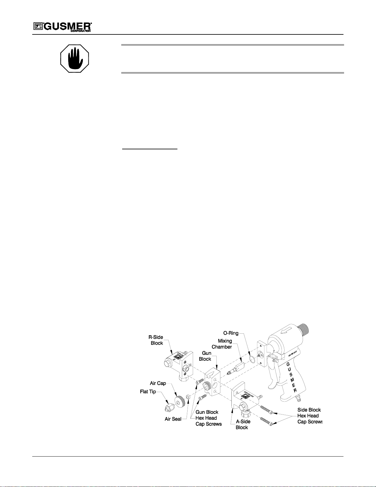
2. REMOVE THE FLAT SPRAY TIP ASSEMBLY- Using the 6” Adjustable
Wrench remove the Flat Tip Assembly from the end of the Mixing Module.
3. REMOVE AIR CAP- Remove the Air Cap from the front of the gun by turning it
counter-clockwise. If necessary, use a pair of Pliers.
4. REMOVE THE GUN FROM THE SIDE BLOCKS- Using the 5/32” Hex Key,
remove the Side Block Mounting Screws. Carefully separate each Side Block from
the Gun Block. If this proves difficult, try removing any dried chemical that may
have accumulated. Wipe mating surfaces clean with a r ag soaked in gun cleaner. If
the Side Blocks require servicing see the Side Block Service Procedure on page 14.
Figure 10. Mixing Chamber and Gun Block Removal/Installation
16 35943-1, Issue 5
Page 17

Operating Manual Servicing Procedures
5. REMOVE AND SERVICE THE GUN BLOCK- Using the 5/32” Hex Key,
remove the two Gun Block Mounting Screws. Slide the block away from the gun. If
removal is difficult, remove anydried chemical from the gun. Wipe mating surfaces
clean with a rag soaked in gun cleaner. Clean the Gun Block with gun cleaner and
Brass Brushes to remove any built up foam, crystallized Isocyanate, etc. This is
important to insure unrestricted movement of the Mixing Chamber.
6. REMOVE AND SERVICE THE MIXING CHAMBER- Using the 3/16” Open
End Wrench or Needle Nose Pliers, hold the end of the Piston Rod. Turn the Mixing
Chamber by hand counter clockwise until it comes free. Clean the Mixing Chamber
with gun cleaner and clean out drills as required. Inspect it for damage, and replace
if necessary.
7. REINSTALL THE MIXING CHAMBER- Using the 3/16” Open End Wrench or
Needle Nose Pliers, hold the flat end of the Piston Rod. Thread the Mixing Chamber
onto the end of the Piston Rod by hand.
8. REINSTALL THE GUN BLOCK- Slide the Gun Block over the Mixing Chamber
and toward the gun. Using the 5/32” Hex Key, install the Gun Block Mounting
Screws. Make sure to sufficiently tighten the screws equally to prevent leakage.
9. REINSTALL THE SIDEBLOCKS ON TH E GUN BLOCK- Using the 5/32”
Hex Key secure the A and R Side Blocks to the Gun Block with the two socket head
cap screws. Make sure to sufficiently tighten the screws equally to prevent leakage.
End Cap and Air Piston O-Ring Service Procedure
NOTE:
If only the End Cap O-Ring
and/or Safety Stop Cup Seal
requires replacing, see the
End Cap O-Ring and Safety
Stop Cup Seal Service
Procedure on page 19.
10. PERFORM START UP PROCEDURE- See Daily Start Up Procedure on Page 12.
TOOLS REQUIRED
• 5/16” Spintite • 5/32” Hex Key
• 7/64” Ball Point Hex Key • 6” Pliers
• 3/16” Open End Wrench
(or Needle Nose Pliers)
• Lubriplate Grease
• Retaining Ring Pliers
1. PERFORM SHUTDOWN PROCEDURE- See the Daily Shutdown Procedure on
Page 12.
2. REMOVE THE GUN FROM THE SIDE BLOCKS- Using the 5/32” Hex Key,
remove the Side Block Mounting Screws. Carefully separate each Side Block from
the Gun Block. If this proves difficult, try removing any dried chemical that may
have accumulated. Wipe mating surfaces clean with a r ag soaked in gun cleaner. If
the Side Blocks require servicing see the Side Block Service Procedure on page 14.
3. REMOVE THE GUN BLOCK- Using the 5/32” Hex Key, remove the Gun Block
Mounting Screws. Carefully remove the Gun Block from the rest of the gun. If
removal is difficult, remove anydried chemical from the gun. Wipe mating surfaces
clean with a rag soaked in gun cleaner. Be sure to retain the O-Ring located between
the Gun Block and Mounting Flange.
12/6/00 17
Page 18
GAP Spray Gun
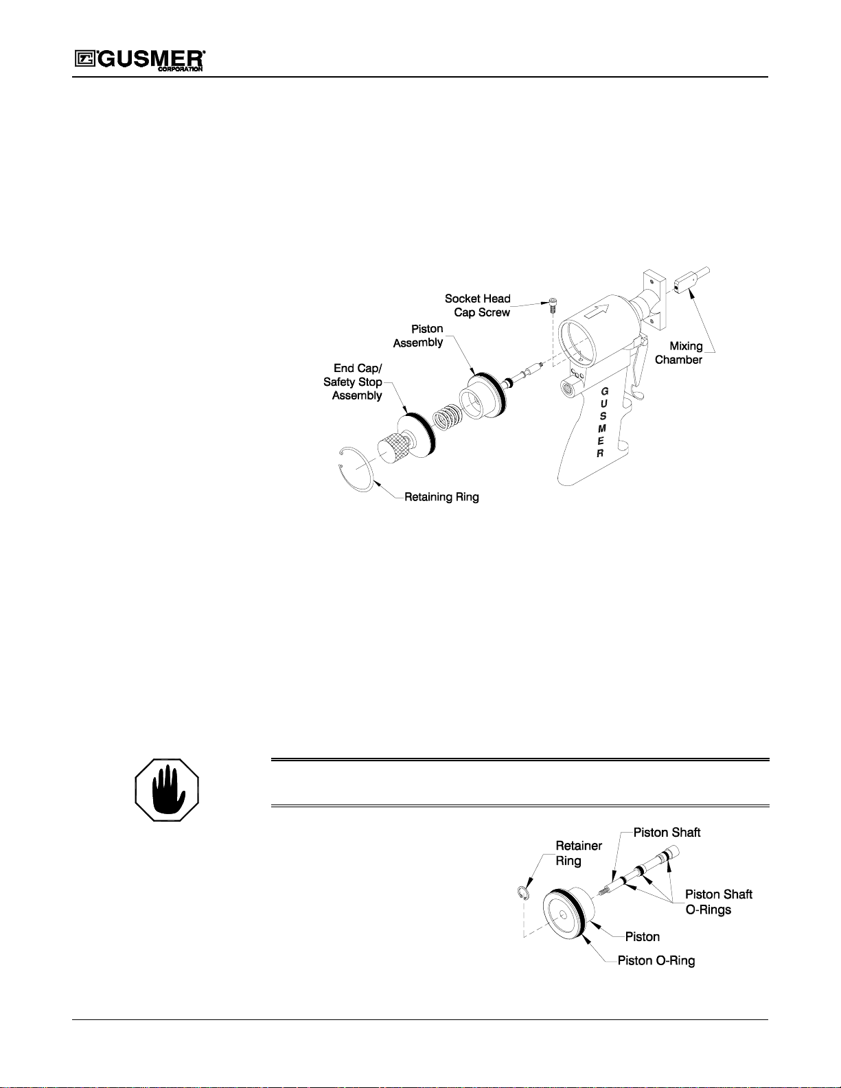
4. REMOVE THE MIXING CHAMBER- Using the 3/16” Open End Wrench or
Needle Nose Pliers, hold the end of the Piston Rod. Turn the Mixing Chamber by
hand counter clockwise until it comes free. If chamber requires servicing, see the
Mixing Chamber and Gun Block Service Procedure.
5. DISENGAGE THESAFETY STOP- Push in and turn the Safety Stop knob
counterclockwise to place the gun in the Open detented position.
6. REMO VE SOCKET HEAD SCREW- Using the 7/64” Ball Point Hex Key remove
the Socket Head Cap Screwfrom the rear the Air Cylinder.
NOTE:
Removing the End Cap will
require some force since the
O-Ring is tightly compressed
Figure 11. End Cap and Piston Assembly
7. REMOVE THE RETAINING RING- Using the Retaining Ring Pliers remove the
Retaining Ring, which maintains the End Cap position in the Air Cylinder.
8. REMOVE THE END CAP/SAFETY STOP ASSEMBLY- Pull the Safety Stop
until it, and the attached End Cap come free from the Air Cylinder. Be sure to retain
the Piston Spring located inside of th e Air Cylinder.
9. INSPECT THE END CAP O-RING- Inspect the O-Ring. If damaged remove it
and install a new O-Ring after lightly coating it with Lubriplate Grease.
10. REMOVE THE PISTON ASSEMBLY- Using the 6” Pliers take hold of the Piston
and pull the assembly out of the Air Cylinder.
WARNING: T
REMOVING THE PISTON ASSEMBLY.
AKE CARE NOT TO DAMGE THE PISTON OR THE AIR CYLINDER WALL WHEN
11. DISASSEMBLE THE PISTON
ASSEMBLY- Remove the Retainer
Ring from the Piston Assembly.
Slide the Piston Shaft Assembly out
from the backside of the Piston.
12. INSPECT THE O-RINGS- Inspect
the O-Rings and remove if damaged.
Carefully install the new O-Rings
after applying Lubriplate Grease.
Figure 12. Piston Assembly
18 35943-1, Issue 5
Page 19
Operating Manual Servicing Procedures
13. REASSEMBLE THE PISTON ASSEMBLY- Slide the Piston Shaft Assembly in
through the backside of the Piston, taking care not to damage the O-Rings. Install the
Retainer Ring on the Piston Assembly.
14. REINSTALL THE PISTON ASSEMBLY- Insert the Piston Assembly into the Air
cylinder.
15. REINSTALL THE END CAP ASSEMBLY AND PISTON SPRING- Center the
Piston Spring over the raised portion of the Piston and insert the End Cap into the Air
Cylinder. Press the End Cap until it moves past the undercut groove in the Air
Cylinder. This groove is where the Retaining Ring nests. Maintain pressure on the
End Cap, making sure the groove remains visible, and install the Retaining Ring
using the Retaining Ring Pliers.
16. REINSTALL SOCKET HEAD SCREW- Using the 7/64” Ball Point Hex Key
reinstall the Socket Head Cap Screw at the rear the Air Cylinder.
WARNING: INSERT THE RETAINING RING COMPLETELY INTO THE GROOVE SO THAT THE END
CAP WILL REMAIN IN THE AIR CYLINDER WHEN THE GUN HAS AIR PRESSURE APPLIED TO IT.
K
EEP CLEAR OF THE CAP WHEN FIRST REAPPLYING AIR PRESSURE OR TRIGGERING THE GUN
AFTER REASSEMBLY IN CASE OF IMPROPER
RETAINING RING INSTALLATION.
17. REINSTALL THE MIXING CHAMBER- Using the 3/16” Open End Wrench or
Needle Nose Pliers, hold the end of the Piston Rod. Thread the Mixing Chamber
onto the threaded portion of the Piston Rod by hand until it is snug.
18. REINSTALL THE GUN BLOCK- Slide the Gun Block over the Mixing Chamber
and toward the gun. Using the 5/32” Hex Key, install the Gun Block Mounting
Screws. Make sure to sufficiently torque the screws.
19. REINSTALL THE SIDE BLOCKS ON THE GUN BLOCK- Using the 5/32”
Hex Key secure the A and R Side Blocks to the Gun Block with the two socket head
cap screws. Make sure to sufficiently tighten the screws equally to prevent leakage.
20. PERFORM START UP PROCEDURE- See Daily Start Up Procedure on Page 12.
End Cap O-Ring and Safety Stop Cup Seal Service Procedure
TOOLS REQUIRED
• Retaining Ring Pliers • 6” Pliers
• 7/64” Ball Point Hex Key • 5/64” Hex Key
• 5/16” Spintite • Lubriplate Grease
• 5/32” Hex Key
1. PERFORM SHUTDOWN PROCEDURE- See the Daily Shutdown Procedure on
Page 12.
12/6/00 19
Page 20
GAP Spray Gun
2. REMOVE THE GUN FROM THE SIDE BLOCKS- Using the 5/32” Hex Key,
remove the Side Block Mounting Screws. Carefully separate each Side Block from
the Gun Block. If this proves difficult, try removing any dried chemical that may
have accumulated. Wipe mating surfaces clean with a r ag soaked in gun cleaner. If
the Side Blocks require servicing see the Side Block Service Procedure on page 14.
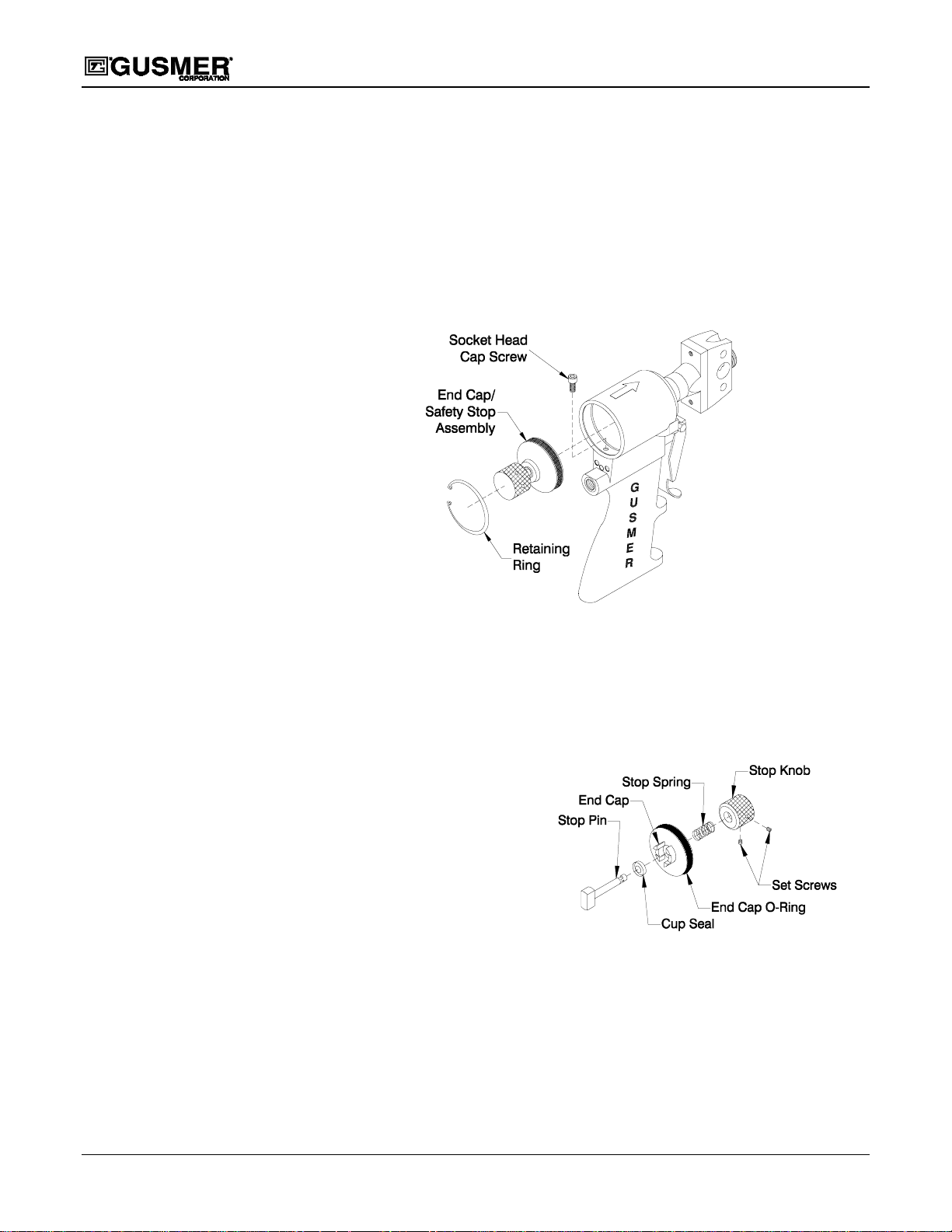
3. REMOVE SOCKET THE HEAD SCREW- Using the 7/64” Ball Point Hex Key
remove the Socket Head Cap Screw from the rear the Air Cylinder.
4. REMOVE THE RETAINING RING- Using the Retaining Ring Pliers remove the
Retaining Ring, which holds the End Cap in place in the Air Cylinder.
NOTE:
Removing the End Cap will
require some force since the
O-Ring is tightly compressed
Figure 13. End Cap Assembly
5. REMOVE THE END CAP/SAFETY STOP ASSEMBLY- Remove the End Cap
and retain the Piston Spring located inside of the Air Cylinder for future use.
6. INSPECT THE END CAP O-RING- Inspect the O-Ring. If damaged remove it
and install a new O-Ring after lightly coating it with Lubriplate Grease.
7. REMO VE THE SAFETY
STOP M ECHANISM-
Using the 5/64” Hex Key
remove the two set screws
from the Stop Knob. Slide
the knob off the shaft of the
Stop Pin. Retain the Shaft
Spring. Pull the Stop Pin
out of the End Cap.
Figure 14. Safety Stop Assembly
8. REPLACE CUP SEAL- Remove and replace the Cup Seal located in the End Cap if
necessary. Lubricate the new cup seal and install it making sure to that the “cup” is
facing the Air Cylinder.
9. REINSTALL THE SAFETY STOP MECHANISM- Insert the Stop Pin into the
End Cap. Slide the Shaft Spring and Stop Knob onto the shaft of the Stop Pin.
Using the 5/64” Hex Keyreinstall the two set screws in the Stop Knob. Make sure
the knob is secure.
20 35943-1, Issue 5
Page 21
Operating Manual Servicing Procedures
10. REINSTALL THE END CAP/SAFETY STOP ASSEMBLY- Center the Piston
Spring over the raised portion of the Piston. Line up the raised portion of the End
Cap with the inside diameter of the Piston Spring and insert the End Cap into the Air
Cylinder. Press the End Cap until it moves past the undercut groove in the Air
Cylinder. This groove is where the Retaining Ring nests. Maintain force on the End
Cap, m aking sure the groove remains visible, and install the Retaining Ring using the
Retaining Ring Pliers.
11. REINSTALL SOCKET HEAD SCREW- Using the 7/64” Ball Point Hex Key
reinstall the Socket Head Cap Screw at the rear the Air Cylinder.
WARNING: INSERT THE RETAINING RING COMPLETELY INTO THE GROOVE SO THAT THE END
CAP WILL REMAIN IN THE AIR CYLINDER WHEN THE GUN HAS AIR PRESSURE APPLIED TO IT.
K
EEP CLEAR OF THE CAP WHEN FIRST REAPPLYING AIR PRESSURE OR TRIGGERING THE GUN
AFTER REASSEMBLY IN CASE OF IMPROPER
RETAINING RING INSTALLATION.
12. REINSTALL THE SIDEBLOCKS ON THE GUN BLOCK-Using the 5/32”
Hex Key secure the A and R Side Blocks to the Gun Block with the two socket head
cap screws. Make sure to sufficiently tighten the screws equally to prevent leakage.
13. PERFORM START UP PROCEDURE- See Daily Start Up Procedure on Page 12.
Trigger Valve O-Ring Procedure
NOTE:
Guns configured with the air
supply connected to the rear
of the Gun, as opposed to the
base of the Gun Handle,
require removal of the Air
Hose and Pipe Nipple using a
6” Adjustable Wrench.
TOOLS REQUIRED
• 5/32” Hex Key • Lubriplate Grease
• 6” Adjustable Wrench • Pin Punch, 1/4” diameter or less
• 6” Pliers • Ball Peen Hammer
• 5/16” Spintite • Gun Cleaner
• 3/16” Hex Key • Clean Rags
1. PERFORM SHUTDOWN PROCEDURE- See the Daily Shutdown Procedure
on Page 12.
2. REMOVE THE GUN FROM THE SIDE BLOCKS- Using the 5/32” Hex Key,
remove the Side Block Mounting Screws. Carefully remove each Side Block from
the Gun Block. If removal is difficult, remove any dried chemical from the gun.
Wipe mating surfaces clean with a rag soaked in gun cleaner. If the Side Blocks
require servicing see the Side Block Service Procedure on page 14.
3. REMO VE THE 1/8” PIPE PLUG FROM THE GUN- Using the 3/16“ Hex Key
remove the 1/8” Pipe Plug from the gun.
4. REMOVE TRIGGER LEVER- Using the 6” Adjustable Wrench and the 6” Pliers
remove the Screw and Locknut that hold the Trigger Lever in place. Remove the
Trigger Lever.
12/6/00 21
Page 22
GAP Spray Gun
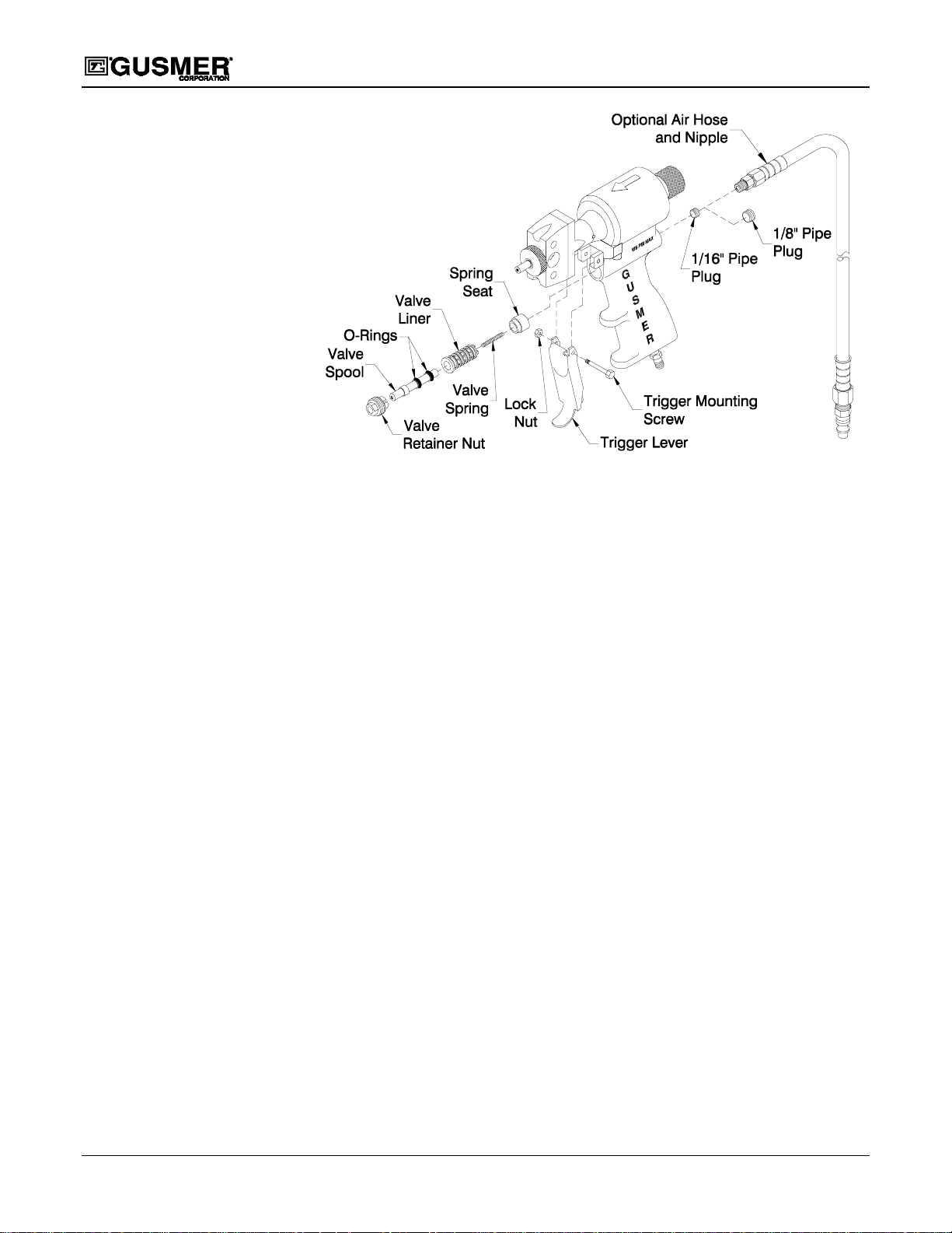
Figure 15. Trigger/Air Valve Assembly
5. REMOVE VALVE RETAINERNUT- Using the 6” Adjustable Wrench, remove
the Valve Retainer Nut. This is the hex shaped nut that surrounds the brass Valve
Spool and holds it in place.
NOTE:
Follow Steps 9 through 16 to
replace the O-rings on the
Valve Liner. If they do not
need replacing go to Step 18.
6. REMOVE THE VALVE SPOOL- Using the 6” Pliers take hold of the end of the
Valve Spool and remove it from the gun. A spring will come out with it. Make sure
not to loose this spring as it belongsin the hole at the end of the Spool.
7. REPLACE THE O-RINGS- If necessary, replace the O-Rings on the Valve Spool
after applying a thin coat of Lubriplate Grease to them.
8. REMOVE THE VALVE LINER- Attempt to pull the Valve Liner out of the gun
handle through the trigger hole. If successful, proceed to Step 11. If unsuccessful,
proceed to Step 9.
9. REMO VE THE REAR INTERNAL 1/16” PIPE PLUG- Deeper in the hole from
which the 1/8” Pipe Plug(or Air Hose) was removed, locate the 1/16” Pipe Plug.
Remove this Plug using the 5/32” Hex Key.
10. REMOVE THE SPRING SEAT- Looking into the hole from which both Plugs
were removed the brass surface of the Spring Seat can be seen. Using the Pin Punch
of ¼” diameter or less, and the Ball Peen Hammer, gently tap the Spring Seat until
both it and the Valve Liner are pushed out the opposite end of the hole.
11. REMOVE & REPLACE THE O-RINGS- Remove and replace the four O-Rings
on the Valve Liner. Apply a light coat of Lubriplate Grease to the O-Rings.
12. CLEAN THE VALVE HOLE AND REMOVE ANY DEBRIS- After insuring
hole is free of any debris apply a thin coat of Lubriplate to the inside of the hole.
13. REINSTALL THE SPRING SEAT- Slide the brass Spring Seat back into the Gun
Handle Air Valve hole tapered end first until it bottoms out in the hole.
22 35943-1, Issue 5
Page 23

Operating Manual Servicing Procedures
14. REINSTALL THE VALVE LINER- Push in the brown Valve Liner as far as it will
go. Some resistance is normal, as there is interference between the O-rings on the
Valve Liner and the inside diameter of the hole. Push it in until two or three internal
threads in the hole are visible. These threads allow engagement of the Valve
Retainer Nut which when screwed in, will align the Valve Liner and Spool to their
proper depth.
NOTE:
If removing the Pipe Plug(s)or
Air Hose was not necessary,
skip Steps 15 and 16.
NOTE:
Guns configured with the air
supply connected to the rear
of the Gun, as opposed to the
base of the Gun Handle,
require reinstallation of the Air
Hose and Pipe Nipple using a
6” Adjustable Wrench.
15. REINSTALL THE 1/16” PLUG- Using the 5/32” HexKey thread the 1/16” Pipe
plug back in place. Apply a small amount of pipe thread sealant to the threads prior
to insertion. This helps seal the threads and prevent air leaks.
16. REINSTALL THE 1/8” PIPE PLUG- Using the 3/16“ Hex Key reinstall the 1/8”
Pipe Plug in the gun.
17. REINSTALL THE VALVE SPOOL- Insert the Valve Spool, with the Valve Spool
Spring in place into the Valve Liner. Screw in the Valve Retainer Nut. Be careful
not to over tighten it, just tighten until it is “snug”.
18. REASSEMBLE THE TRIGGER LEVER- Reinstall the Trigger Lever using the
Screw and Lock Nut. Tighten using the 6” Adjustable Wrench and the 6”Pliers.
19. REINSTALL THE SIDE BLOCKS ON THE GUN BLOCK- Using the 5/32”
Hex Key secure the A and R Side Blocks to the Gun Block with the two socket head
cap screws. Make sure to sufficiently tighten the screws equally to prevent leakage.
20. PERFORM STARTUPPROCEDURE-SeeDailyStartUp Procedure onPage12.
12/6/00 23
Page 24
AIR PASSAGE DIAGRAMS
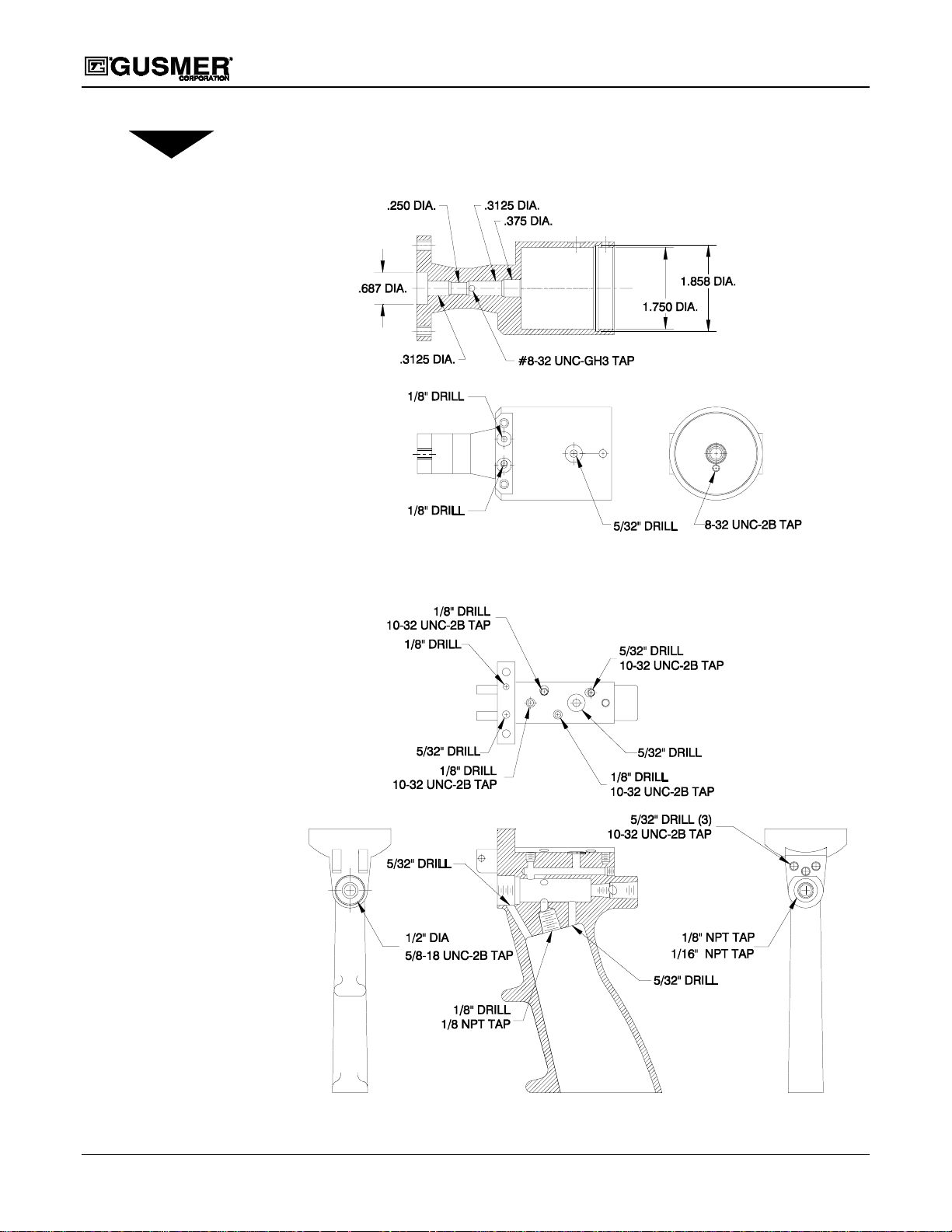
NOTE:
Be sure to use thread
sealant when reinstalling
any threaded components
removed from the gun. In
addition, all sets crews should
be reinstalled flush
to the outside surface of the
gun handle.
GAP Spray Gun
Figure 16. Air Cylinder Air Passages
Figure 17. Handle Air Passages
24 35943-1, Issue 5
Page 25
Operating Manual Appendix
APPENDIX
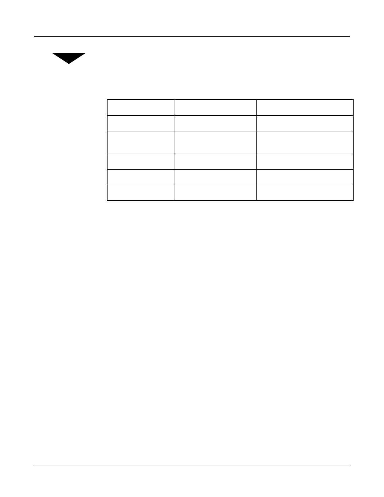
Specifications
Technical Data US Metric
Maximum Output:
Maximum Operating
Pressure:
Air Supply
Weight:
Dimensions:
40 lbs./min 18 kg/min
3000 psi 207 bar
100-125 psi 7-9 bar
2.34 lbs. 1.06 kg
H=7"/W=7"/D=4.4" H=17.8cm/W=17.8cm/D=11.2cm
12/6/00 25
Page 26
NOTES
GAP Spray Gun
26 35943-1, Issue 5
Page 27

Operating Manual Instruction Manual Discrepancy Report
INSTRUCTION MANUAL DISCREPANCY REPORT
Field
Number
1Date
2
3
4
5
6
7
Name
IM Number
Issue Number
Date of Issue
Page Number
Discrepancy
Field Title Description
Instructions:
Complete the above fields of the form by following the instructions listed on the reverse side of this sheet and mail to:
Gusmer Corporation
One Gusmer Drive PO Box 2055
Lakewood, NJ 08701
12/6/00 27
Page 28

GAP Spray Gun
Field
Number
1
2
3
4
5
6
7
Field Title Description
Date
Name
IM Number
Issue Number
Enter date report is submitted.
Enter name of person making report.
Enter the Part Number of the Instruction Manual from the title page.
Enter the Issue number of the Instruction Manual from the title page. If there is no
issue number, enter NONE.
Date of Issue
Enter the date of Issue of the Instruction Manual from the title page. If there is no
issue date, enter NONE.
Page Number
Discrepancy
Enter the page number containing the discrepancy
Provide a brief description of discrepancy
NOTE: You may send a marked copy of the page as an attachment to your
submittal.
28 35943-1, Issue 5
 Loading...