


Model FF-2500
Proportioning Unit
Operating Manual
25942-1
February 12, 2004
Issue 4
GUSMER CORPORATION ®
A Subsidiary of Gusmer Machinery Group, Inc.
One Gusmer Drive
Lakewood, New Jersey, USA 08701-8055
Toll Free 1-800-367-4767 (USA & Canada)
Phone: (732) 370-9000
Fax: (732) 905-8968
®
Copyright 2004, GUSMER CORPORATION
NOTICE: This manual contains important information about your GUSMER equipment. Read and retain for future reference.
http://www.gusmer.com

Model FF-2500 Proportioning Unit
NOTICE:
The equipment described in this technical manual must only be operated or serviced by properly trained individuals,
thoroughly familiar with the operating instructions and limitations of the equipment. For technical service, call your local
distributor. Call: 1-800-FOR-GSMR (1-800-367-4767) for the name and telephone number of your local distributor.
NOTICE:
All statements, information and data given herein are believed to be accurate and reliable but are presented without
guarantee, warranty or responsibility of any kind expressed or implied. Statements or suggestions concerning possible use of
GUSMER equipment are made without representation or warranty that any such use is free of patent infringement, and are
not recommendations to infringe any patent. The user should not assume that all safety measures are indicated or that other
measures may not be required for a particular circumstance or application.
2 25942-1, Issue 4

Operating Manual Contents
CONTENTS
LIST OF FIGURES..........................................................................................................4
WARRANTY....................................................................................................................5
GENERAL SAFETY INFORMATION.........................................................................6
ACCEPTABLE EQUIPMENT USES ......................................................................................6
OPERATIONAL SAFETY PROCEDURES ..............................................................................7
DESCRIPTION ................................................................................................................8
SPECIFICATIONS........................................................................................................11
INITIAL MACHINE SET-UP ......................................................................................12
MAIN POWER INSTALLATION ........................................................................................13
MATERIAL SUPPLY CONNECTIONS ................................................................................14
HOSE HEAT POWER PACK .............................................................................................15
TEMPERATURE CONTROLLERS ......................................................................................16
HEATED HOSE INSTALLATION.......................................................................................17
AIR PURGE ....................................................................................................................20
OPERATION..................................................................................................................21
DAILY START-UP PROCEDURE.......................................................................................21
DAILY SHUT-DOWN PROCEDURE ..................................................................................22
TROUBLESHOOTING.................................................................................................23
GENERAL INTRODUCTION..............................................................................................23
PRIMARY HEATING SYSTEM..........................................................................................24
Solutions...................................................................................................................25
PROPORTIONING SYSTEM ..............................................................................................27
Solutions...................................................................................................................27
HOSE HEAT SYSTEM......................................................................................................30
Solutions...................................................................................................................30
MAINTENANCE ...........................................................................................................34
PROPORTIONING PUMPS ................................................................................................34
PUMP BASES..................................................................................................................34
INLET FILTER SCREEN ...................................................................................................35
INSTRUCTION MANUAL DISCREPANCY REPORT ...........................................37
2/12/04 3
ISOCYANATE PUMP LUBRICANT ....................................................................................36

Model FF-2500 Proportioning Unit
LIST OF FIGURES
FIGURE 1. MODEL FF-2500 PROPORTIONING UNIT...........................................................8
FIGURE 2. TYPICAL FF-2500 INSTALLATION....................................................................12
FIGURE 3. MAIN POWER CONNECTIONS...........................................................................13
FIGURE 4. MANUAL TRANSFORMER CONNECTIONS........................................................... 15
FIGURE 5. MANUAL TAP SETTINGS...................................................................................15
FIGURE 6. TEMPERATURE CONTROLLER...........................................................................16
FIGURE 7. ISOLATION HOSES...........................................................................................17
FIGURE 8. HOSE CONNECTION STEP (A)...........................................................................17
FIGURE 9. HOSE CONNECTION STEP (B & C)....................................................................18
FIGURE 10. HOSE CONNECTION STEP (D)........................................................................18
FIGURE 11. HOSE CONNECTION STEP (E & F)..................................................................18
FIGURE 12. TEMPERATURE SENSING UNIT (TSU).............................................................19
FIGURE 13. PUMP LUBRICANT CUP .................................................................................20
FIGURE 14. PRIMARY HEATER FEATURES.........................................................................24
FIGURE 15. PROPORTIONING PUMP FEATURES .................................................................27
FIGURE 16. TRANSFORMER FUSE LOCATION........................................................................29
FIGURE 17. TERMINAL JUMPER STRIP INSTALLATION........................................................32
4 25942-1, Issue 4

Operating Manual Contents
WARRANTY
Gusmer Corporation (Gusmer) provides a limited warranty to the original purchaser (Customer) of
Gusmer manufactured parts and equipment (Product) against any defects in material or
workmanship for a period of one year from the date of shipment from Gusmer facilities.
In the event Product is suspected to be defective in material or workmanship, it must be returned to
Gusmer, freight prepaid. If Product is found to be defective in material or workmanship, as
determined solely by Gusmer, Gusmer will issue full credit to Customer for the freight charges
incurred in returning the defective Product, and either credit will be issued for the replacement cost
of the Product or a replacement part will be forwarded no-charge, freight prepaid to Customer.
This warranty shall not apply to Product Gusmer finds to be defective resulting from: installation,
use, maintenance, or procedures not accomplished in accordance with our instructions; normal
wear; accident; negligence; alterations not authorized in writing by Gusmer; use of “look alike”
parts not manufactured or supplied by Gusmer; or Product used in conjunction with any other
manufacturer's pumping or proportioning equipment. For such Product, a written estimate will be
submitted to the Customer at a nominal service charge, itemizing the cost for repair. Disposition of
Product will be done in accordance with the terms stated on the written estimate.
The warranty provisions applied to product that are not manufactured by Gusmer will be solely in
accordance with the warranty provided by the original manufacturer of the product.
GUSMER MAKE S N O WA RR ANTY WH ATSO EV ER AS TO THE MER CH ANT ABI LITY O F,
OR SUITABILITY FOR, ITS PRODUCT TO PERFORM ANY PARTICULAR PURPOSE.
CREDIT FOR, OR REPLACEMENT OF, PRODUCT DEFECTIVE IN MATERIAL OR
WORKMANSHIP SHALL CONSTITUTE COMPLETE FULFILLMENT OF GUSMER
OBLIGATIONS TO CUSTOMER. NO OTHER WARRANTY, EXPRESS OR IMPLIED ON
ANY PRODUCT IT MANUFACTURES AND/OR SELLS, WILL BE RECOGNIZED BY
GUSMER UNLESS SAID WARRANTY IS IN WRITING AND APPROVED BY AN OFFICER
OF GUSMER.
Under no circumstances shall Gusmer be liable for loss of prospective or speculative profits, or
special indirect, incidental or consequential damages. Further, Gusmer shall have no liability for
any expenses including, but not limited to personal injury or property damage resulting from failure
of performance of the product, use of the product, or application of the material dispensed through
the product. Any information provided by Gusmer that is based on data received from a third
source, or that pertains to product not manufactured by Gusmer, while believed to be accurate and
reliable, is presented without guarantee, warranty, or responsibility of any kind, express or implied.
Gusmer through the sale, lease, or rental of Product in no way expresses or implies a license for the
use of, nor encourages the infringement of any patents or licenses.
To ensure proper validation of your warranty, please complete the warranty card and return it to
Gusmer within two weeks of receipt of equipment.
Revised 09/02
2/12/04 5

Model FF-2500 Proportioning Unit
GENERAL SAFETY INFORMATION
It is necessary to understand and follow the instructions in this manual to ensure proper
and safe operation of the equipment.
As with most mechanical equipment, certain safety precautions must be taken when the
equipment discussed in this manual is operated or serviced. Severe bodily injury or
damage to equipment and property may result if the instructions and precautions listed
throughout this manual are not followed.
Needless to say, sufficient guidelines cannot be developed to eliminate the need for good
common sense in the use and servicing of this equipment, and in the use and application
of the products, this equipment has been designed to process. Users of this equipment
must therefore, make their own determination as to the suitability of the information
contained in this manual to their specific operation and requirements. There should be
no assumption made that the safety measures and instructions contained herein are allinclusive, and that other safety measures may not be required for specific use or
application.
The following safety guidelines are generally applicable to the safe and efficient use of
the equipment.
Acceptable Equipment Uses
The equipment is designed for the dispensing of polyurethane foams, two-component
coating systems such as polyureas, and some two-component epoxy systems. Under no
circumstances should any acid or corrosive chemicals be used in the unit. Consult
GUSMER if there is any doubt about the compatibility of the chemical system to be used
in this equipment.
Any use of this equipment other than as indicated above constitutes misuse unless
express written approval is obtained from GUSMER.
Your Gusmer equipment incorporates design parameters, features, and functionality
developed in over 40 years of plural component equipment design and manufacture. It is
manufactured under the stringent standards of ISO 9001, and is backed by the Gusmer
Warranty included herein.
The use of genuine Gusmer replacement parts is recommended for your equipment.
Substitution of parts not designed, manufactured, or recommended by Gusmer may result
in reduced performance of, and/or damage to, your Gusmer equipment. Any alterations
to, or substitutions for, genuine Gusmer parts shall void the provisions of the Gusmer
Warranty.
6 25942-1, Issue 4
Operating Manual General Safety Information
Operational Safety Procedures
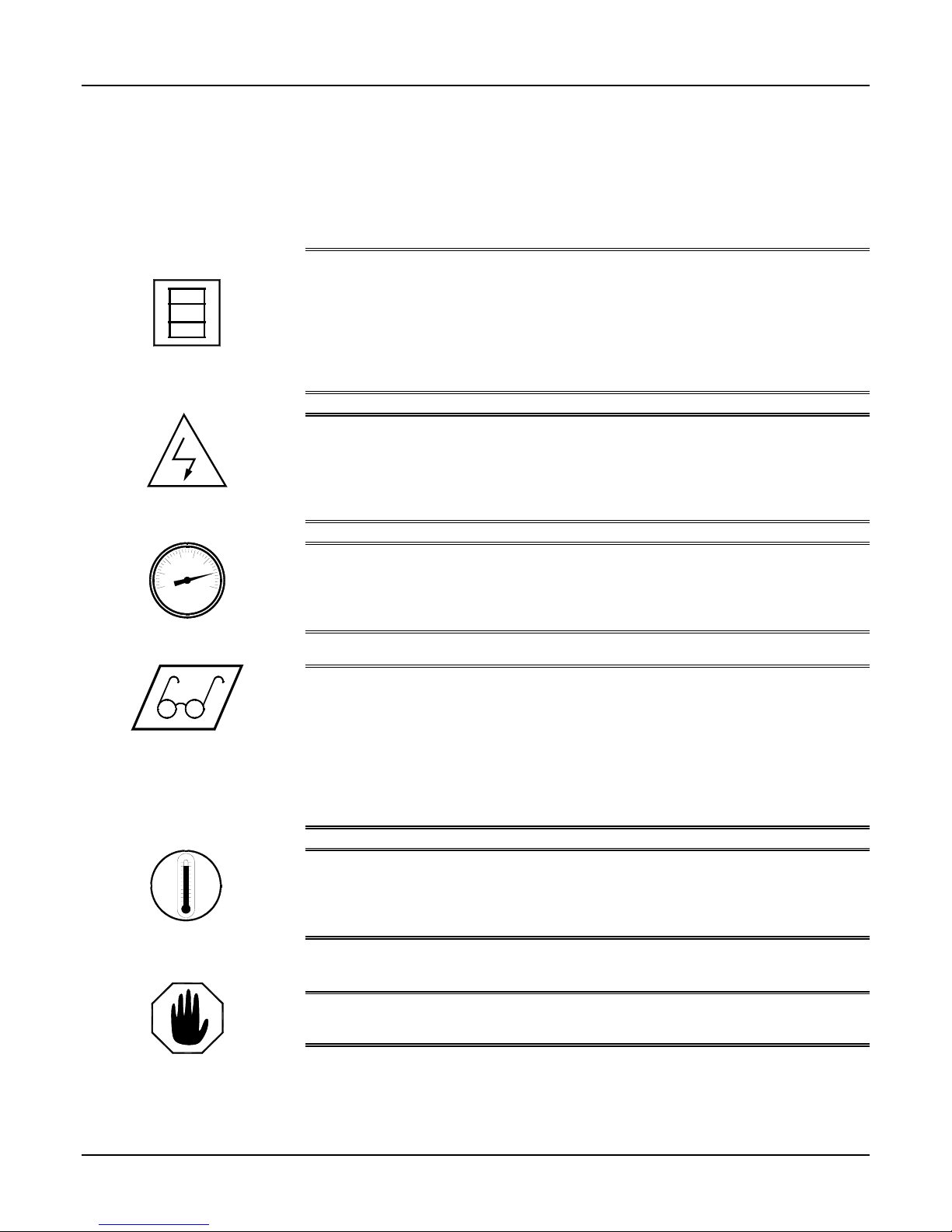
This safety information will not be repeated in the text of this manual. The symbols
pertaining to this information will appear where appropriate to alert the operator to
potential hazards.
Solvents and Chemicals
High Voltage
High Pressure
Personal Protective
Equipment
WARNING: T
OPERATOR TO CERTAIN HAZARDS. ADEQUATE PERSONAL PROTECTIVE MEASURES MUST BE
TAKEN SO AS TO AVOID EXCEEDING THE
BEING USED
HE SOLVENTS AND CHEMICALS USED WITH THIS EQUIPMENT EXPOSE THE
THRESHOLD LIMIT VALUE (TLV) OF THE PRODUCTS
, AS ESTABLISHED BY THE OCCUPATIONAL SAFETY AND HEALTH ADMINISTRATION
(OSHA) OR OTHER QUALIFIED AGENCY. OBTAIN INFORMATION CONCERNING PERSONAL
PROTECTION AND PROPER HANDLING FROM THE SUPPLIER OF SUCH SOLVENTS AND
CHEMICALS
WARNING:
THE ELECTRIC CONSOLES OR OTHERWISE SERVICE THIS EQUIPMENT AND/OR EQUIPMENT USED
WITH IT BEFORE SWITCHING OFF THE MAIN POWER DISCONNECT AND SHUTTING OFF AND
LOCKING OUT SUPPLY VOLTAGE AT THE SOURCE
INSTALLED AND MAINTAINED BY A QUALIFIED ELECTRICIAN
WARNING:
CHEMICAL COMPONENTS CAPABLE OF PRODUCING UP TO 3500 PSI. TO AVOID SERIOUS
BODILY INJURY FROM INJECTION OF FLUID
COMPONENTS WITHOUT BLEEDING ALL PRESSURES TO ZERO
WARNING:
FOR THE TASK BEING ACCOMPLISHED, MUST BE WORN WHEN OPERATING, SERVICING, OR BEING
PRESENT IN THE OPERATIONAL ZONE OF THIS EQUIPMENT
LIMITED TO
EQUIPMENT AS REQUIRED TO PROVIDE PERSONAL PROTECTION FROM SOLVENTS AND
CHEMICALS
HAZARDS ASSOCIATED WITH HYDRAULIC
APPROPRIATE WARNINGS ON THIS PAGE FOR FURTHER INFORMATION
.
TO PREVENT SERIOUS BODILY INJURY FROM ELECTRICAL SHOCK, NEVER OPEN
. THE ELECTRICAL SERVICE MUST BE
.
THIS EQUIPMENT HAS OR IS USED WITH EQUIPMENT THAT HAS HYDRAULIC AND
, NEVER OPEN OR SERVICE ANY CONNECTIONS OR
.
TO AVOID SERIOUS BODILY INJURY, PROPER PROTECTIVE GEAR, APPROPRIATE
. THIS INCLUDES, BUT IS NOT
, EYE AND FACE PROTECTION, GLOVES, SAFETY SHOES, AND RESPIRATORY
; HIGH PRESSURE RELEASES; HIGH TEMPERATURES; ELECTRIC SHOCK; AND OTHER
/ELECTRO-MECHANICAL EQUIPMENT. REFER TO THE
.
WARNING: T
TEMPERATURE COMPONENTS SUCH AS PRIMARY HEATERS AND HEATED HOSES. TO PREVENT
SERIOUS BODILY INJURY FROM HOT FLUID OR HOT METAL
EQUIPMENT BEFORE ALLOWING IT TO COOL
High Temperature
WARNING:
SYMBOL MAY RESULT IN PERSONAL INJURY AND/OR DAMAGE TO THE EQUIPMENT.
Warning
2/12/04 7
HIS EQUIPMENT HAS OR IS USED WITH EQUIPMENT THAT HAS HIGH
, NEVER ATTEMPT TO SERVICE THE
.
FAILURE TO READ AND FOLLOW THE INFORMATION ASSOCIATED WITH THIS
Model FF-2500 Proportioning Unit
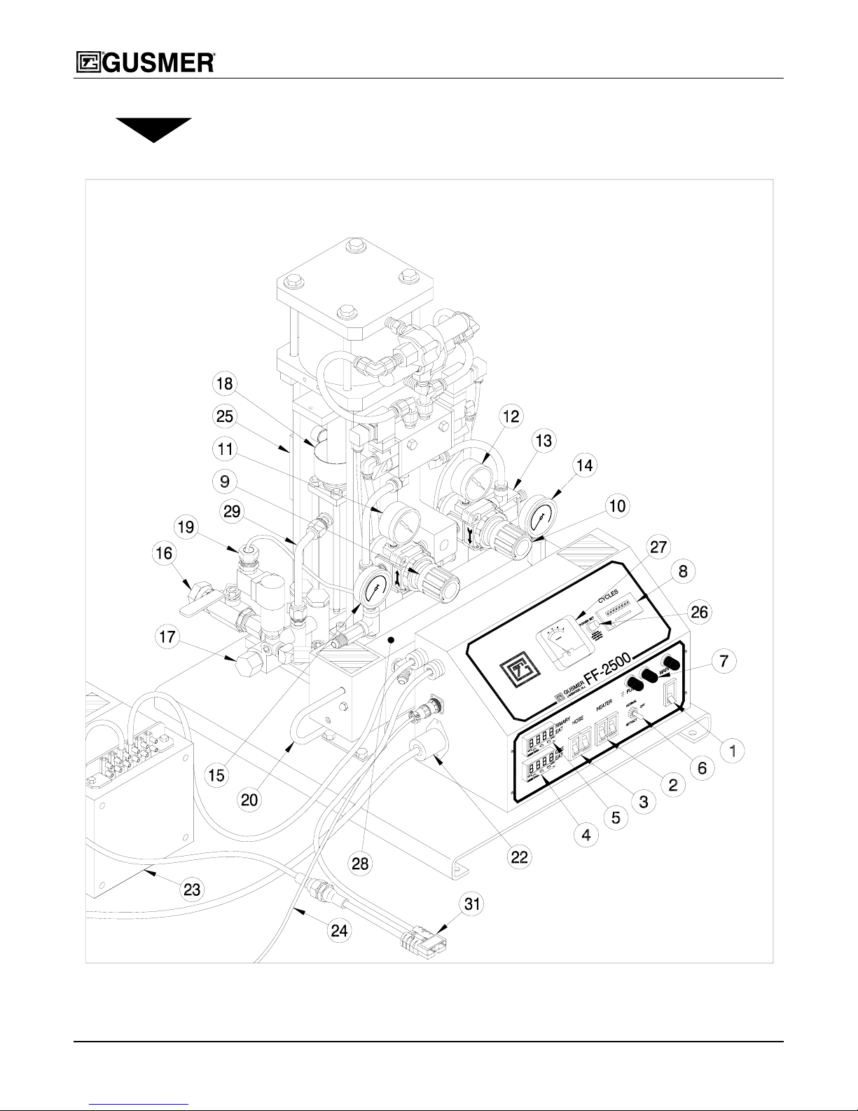
DESCRIPTION
Figure 1. Model FF-2500 Proportioning Unit
8 25942-1, Issue 4

Operating Manual Description
1. MAIN SWITCH - Controls power to all circuits and must be ON for any function
of the proportioning unit to operate.
White pilot light indicates the main switch is ON.
WARNING:
ENERGIZED WHEN THE MAIN SWITCH IS OFF. TO FULLY DE-ENERGIZE THE ELECTRICAL
CONSOLE
2. PRIMARY HEATER CIRCUIT BREAKER- Controls and protects the primary
INCOMING POWER LEADS FROM THE MAIN ELECTRICAL SOURCE REMAIN
, SWITCH OFF AND LOCK OUT INCOMING POWER AT THE SOURCE.
heater. It must be ON for the primary heater to operate.
3. HOSE HEATER CIRCUIT BREAKER- Controls and protects the low voltage
power pack. It must be ON for the hose heater to operate.
4. HOSE TEMPERATURE CONTROLLER- Controls the temperature of the hose
heater. Adjust the set point to the desired temperature. From this point, the
temperature control is automatic.
5. PRIMARY HEATER TEMPERATURE CONTROL- Controls the temperature
of the primary heater. Adjust the set point to the desired temperature. From this
point, the temperature control is automatic.
6. PUMP SWITCH- Controls operation of the air drive system.
• OFF- Air drive system is off.
• NORMAL- Must be in this position for the proportioning pumps to operate.
• RETRACT- Use this position for shutdown. It will stop the air motor at the
bottom of the stroke with the proportioning pumps in the retracted position.
7. PUMP DIRECTIONAL INDICATOR LIGHTS (Amber)- Indicate the direction
the proportioning pump is traveling. Both lights will be off when the pump switch is
OFF or when either proportioning pump exceeds its designed operating pressure
limit.
8. COUNTER- Records the cycle count of the proportioning pumps. One cycle count
equals two (2) strokes (one in each direction).
9. DOWNSTROKE AIR PRESSURE REGULATOR- Controls the air pressure to
the air motor on the downstroke.
10. UPSTROKE AIR PRESSURE REGULATOR- Controls the air pressure to the air
motor on the upstroke.
11. DOWNSTROKE AIR PRESSURE GAUGE- Displays the air pressure in the air
drive system during the downstroke.
12. UPSTROKE AIR PRESSURE GAUGE- Displays the air pressure in the air drive
system during the upstroke.
13. MAIN AIR FILTER- Filters the system air supply.
14. RESIN PRESSURE GAUGE- Displays the pressure in the resin proportioning
2/12/04 9
system.

Model FF-2500 Proportioning Unit
15. ISOCYANATE PRESSURE GAUGE- Displays the pressure in the isocyanate
proportioning system.
16. A-INLET SUPPLY VALVE (R on other side)
17. A-INLET FILTER SCREEN (R on other side)
18. A-PACKING NUT, LUBE CUP (R on other side)
19. PRESSURE LIMIT SWITCH- Factory set to turn off the air drive system when
the proportioning pump exceeds the designed operating pressure limit. (A side
shown, R on other side)
20. PRIMARY HEATER THERMOCOUPLE– Senses the temperature of the
primary heater and inputs that information.
21. THERMAL LIMIT SWITCH- (under thermostat cover not shown)
Interrupts power to the primary heater when the surface temperature approaches the
designed operating temperature limit.
22. POWER PACK (TRANSFORMER) CORD- Provides AC power to the primary
side of the transformer.
23. LOW VOLTAGE POWER PACK (TRANSFORMER)- Provides selectable low
voltage outputs for heating various chemical hose lengths.
24. TSU EXTENSION ADAPTER- Carries the electrical signal from the TSU sensor
in the isocyanate hose to the hose temperature controller.
25. AIR MOTOR REVERSING SWITCH- Energizes and de-energizes the air valve
coils to reverse direction.
26. HOSE HEAT POWER SET- Adjusts the amount of amperage supplied to the hose
heating system.
27. HOSE HEAT AMMETER- Indicates the amount of amperage supplied to the hose
heating system.
28. PRIMARY HEATER- Heats the materials to the required dispensing temperature.
29. A- (ISOCYANATE) PROPORTIONING PUMP- Draws in and dispenses a fixed
volume of isocyanate for delivery to the gun or pour head.
30. R- (RESIN) PROPORTIONING PUMP- (Opposite side, not shown) Draws in and
dispenses a fixed volume of resin for delivery to the gun or pour head.
31. POWER-LOCK™ HOSE HEAT CONNECTION- Connects power from the
transformer to the heated hoses.
10 25942-1, Issue 4

Operating Manual Description
SPECIFICATIONS
MATERIAL SUPPLY:
AIR MOTOR:
ELECTRICAL:
WEIGHT:
DIMENSIONS:
PROPORTIONING PUMPS:
Required chemical viscosity: 250-1500 centipoise (cP). Consult your chemical supplier
about material temperatures required to maintain correct viscosity.
Protect the chemical supply from atmospheric moisture with a blanket of dry nitrogen or
desiccated air.
Resin Inlet: 3/4" NPT (FE) swivel
Isocyanate Inlet: 1/2" NPT (FE) swivel
Material supply pressure: 400 psi maximum (27 bars)
32 scfm @112 psi (12 liters/sec @7.7 bars)
38 amps @ 220 volts, 50/60 Hertz single-phase, AC.
29 amps @ 380 volts, 50/60 Hertz three-phase, AC.
140 pounds (63 kg)
Height: 24 inches (61 centimeters)
Width: 26 inches (66 centimeters)
Depth: 30 inches (76 centimeters)
Operating
Pressure:
2500 psi (173 bars)
Output: 10 lbs./min. (4.54 kg/min) *
INLET FILTER:
PRIMARY HEATER:
HOSE LENGTH:
*Theoretical: actual results will vary with operating conditions.
80 Mesh Standard (Optional - 60/40 Mesh)
6000 Watts: ∆ t=40°F (22°C) @ 10 lb./min. (4.5 kg/min) *
310 feet (94.5 meters) maximum for heating purposes
2/12/04 11
Model FF-2500 Proportioning Unit
INITIAL MACHINE SET-UP
12 25942-1, Issue 4
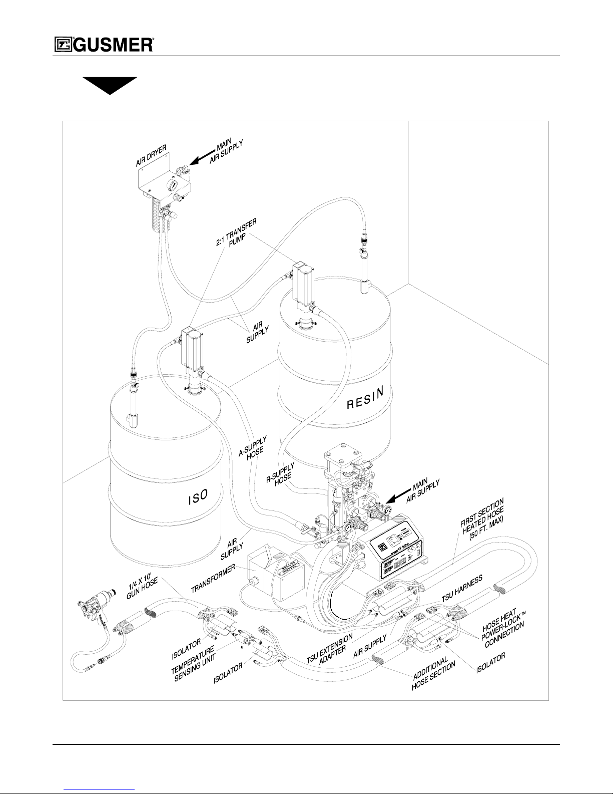
Figure 2. Typical FF-2500 Installation
Operating Manual Initial Machine Set-up
The Accessory Package included with the unit contains the following parts required for setup:
• Tape Roll
• Isolator
• (2) Swivel Unions
• Isolation Hoses
Blue – Resin
Red – Isocyanate
• Temperature Sensing Unit (TSU)
• Parts Identification Manual
• Binder
• Warranty Card
• Hose Jumper Plug
• TSU Extension Adapter ∗
• 1/4 x 30” (76 cm) Air Hose
∗ Refer to Figure 2 for additional parts required for set-up.
IMPORTANT: Complete and return the Warranty Validation Card within 2 weeks
of receipt of equipment.
Main Power Installation
WARNING: BEFORE PROCEEDING, BE SURE THAT INCOMING POWER IS DISCONNECTED AND
LOCKED OUT AT THE SOURCE.
IMPORTANT: The main power source must be capable of meeting the electrical
requirements specified on the nameplate of the proportioning unit and an accessible
quick disconnect provided.
1. Remove and retain four (4) screws from the console cover. Open the cover.
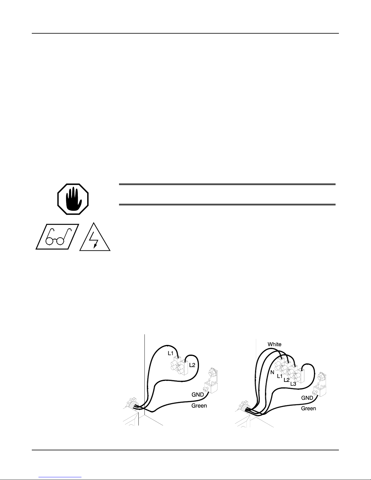
2. Connect the main power cord to the electrical console using wire size #10 or larger.
(Not supplied) (See Figure 3.)
a) Feed the power cord through the strain relief in the back of the console and
connect the power leads to L1 and L2 (220V) –or- L1, L2 and L3 (380V).
b) Connect the ground wire to the ground lug.
c) For 380V models, connect the white Neutral lead to position N on the terminal
block.
(220V Single-Phase) (380V-Three Phase)
2/12/04 13
Figure 3. Main Power Connections

Model FF-2500 Proportioning Unit
3. Close the console cover. Reinstall the four (4) screws retained from Step 1.
4. Set up the chemical supply, air supply and moisture control systems as required.
See the system instructions for proper set-up and operating procedures.
5. Properly ground all auxiliary equipment. If not grounded, the high velocity flow of
fluid can create a static charge, which may spark and cause fire or explosion.
Certain solvents that are commonly in use with this equipment are flammable and
may present a flash danger to the operator.
a) Ground the material supply (transfer pumps/day tanks).
b) The 2:1 transfer pump has a ground lug. Ground the pump in accordance with
the instructions provided with the pump.
c) Check that the proportioning unit ground at the main electrical source is
installed in accordance with the National Electrical Code. If a generator will
be powering the unit, consult with your electrician about additional grounding
measures that may be required.
Material Supply Connections
Connect the material supply to the inlets of the proportioning unit as follows:
1. Ensure that the A- and R- inlet ball valves on the proportioning unit are closed.
2. Connect and tighten the R- (resin) supply hose to the 3/4 FPT swivel fitting on the
R- inlet ball valve, and to the resin transfer pump.
3. Connect and tighten the A- (isocyanate) supply hose to the 1/2 FPT swivel fitting on
the A- inlet ball valve, and to the isocyanate transfer pump.
4. Connect the air supply to the 1/4 MPT nipple on the 2:1 transfer pump. Remove the
cap to access it.
5. Connect the main air supply to the proportioning unit. The main air inlet at the air
filter requires a 3/8 NPT fitting.
IMPORTANT: The main air supply must be clean and free of contaminants.
A minimum of 3/8-inch inside diameter air line (not supplied) should be used to
deliver the air supply to the proportioning unit. A main air shutoff valve to the
proportioning unit is recommended.
14 25942-1, Issue 4

Operating Manual Initial Machine Set-up
Hose Heat Power Pack
The power pack provides low-voltage electrical power to the heating element embedded
in each section of hose. The output voltage of the power pack is adjusted by changing
the tap settings of the transformer. To ensure proper functioning of the heated hoses, the
transformer tap settings must be adjusted to match the total length of hose to be used.
To connect the power pack and select the correct tap settings, proceed as follows:
1. Turn OFF and lock out incoming electrical power at the source.
2. Plug the tap wire with inline fuse (B) into the Power-Lock hose heat connector on
the end of the console wire (A). (See Figure 4.)
™
Figure 4. Manual Transformer Connections
3. Using Figure 5 and the chart below, connect the power lead (C) and the tap wire (B)
to the transformer taps that match the hose length to be used.
IMPORTANT: The power pack must be set to match the hose length used. Too
much power will cause the ho se heat circuit fuse to open ; too little power will result
in insufficient hose heating.
Hose Length
Tap Wire Power Lead
25 ft. (7.6m) S1 S2
35 ft. (10.6m) S2 S3
60 ft. (18.2m) S1 S3
110 ft. (33.3m) S1 S4
160 ft. (48.5m) S4 S5
210 ft. (63.6m) S3 S5
260 ft. (78.8m) S1 S5
310 ft. (94m) S1 S5
Figure 5. Manual Tap Settings
4. Connect the power cord (D) from the power pack to the electric console. Twist the
2/12/04 15
plug to lock it into the receptacle.

Model FF-2500 Proportioning Unit
Temperature Controllers
The FF-2500 digital temperature controllers automatically maintain the temperature
selected for both the hose heat system and primary heater. Each controller has its own
program and is not interchangeable with the other. (See Figure 6.)
To enter the set point, proceed as follows:
NOTE:
The temperature controller
normally displays the set point.
When illuminated, the red LED
number 1 on the temperature
controller indicates that the heater
is in heating mode. The LED goes
out when the liquid in the heater
reaches the set temperature. The
LED will continue to cycle on and
off, indicating that the controller is
maintaining the set point
temperature.
WARNING: DO NOT
PROCEDURES ARE COMPLETED AND THE HEATERS COMPLETELY FILLED WITH CHEMICAL.
DDITIONALLY, DO NOT CHANGE ANY OF THE PREPROGRAMMED PARAMETERS.
A
TURN THE TEMPERATURE CONTROLLER ON UNTIL ALL PURGING
a) Check that the red main disconnect is ON. The white pilot light should be lit.
b) Check that the amber control
power switch is ON. The light
within the switch should be lit.
c) To enter or change the set point,
press and hold the “Set” button
down while pressing the
or
button to increase or decrease
the value. After entering the set
point release the “Set” button and
the set point should display after
10 seconds.
WARNING:
PROGRAMMABLE. IF YOU ENCOUNTER ANY PROBLEMS WITH EITHER CONTROLLER CONTACT
THE CONTROLLERS ARE FACTORY PROGRAMMED AND ARE NOT FIELD
Figure 6. Temperature Controller
GUSMER FOR A REPLACEMENT. DO NOT SUBSTITUTE A CONTROLLER FROM AN ALTERNATE
SUPPLIER AS ITS USE MAY RESULT IN DAMAGE TO THE EQUIPMENT AND
/OR BODILY INJURY.
16 25942-1, Issue 4

Operating Manual Initial Machine Set-up
Heated Hose Installation
WARNING:
FOLLOWING:
SOCYANATE HOSES ARE COLOR-CODED RED AND RESIN HOSES ARE COLOR-CODED BLUE FOR
I
POSITIVE IDENTIFICATION
DIFFERENT THREAD SIZES TO VIRTUALLY ELIMINATE INTERCHANGING THE HOSES
TO MAKE PROPER AND SAFE HOSE CONNECTIONS, READ AND UNDERSTAND
. IN ADDITION, THE RESIN AND ISOCYANATE HOSE FITTINGS HAVE
.
HE HOSE CONNECTION POINTS ARE A POTENTIAL SOURCE OF CHEMICAL AND AIR LEAKS AND
T
ARE THE AREAS MOST EXPOSED TO DAMAGE FROM SCUFFING AND SNAGGING ON ABRASIVE
SURFACES
SCUFF JACKET TO PROTECT THE HOSES AND
1. Connect the isolation hoses to
. GUSMER CORPORATION STRONGLY RECOMMENDS INSTALLING THE OPTIONAL
TSU EXTENSION HARNESS FROM DAMAGE.
their respective primary heater
outlet fittings (see Figure 7).
IMPORTANT: The heated hose
assemblies are connected end to
end during shipment to protect
them from moisture intrusion. Do
not separate the hoses until they
are ready to connect to the
proportioning unit.
Figure 7. Isolation Hoses
2. Plug the TSU extension adapter into the left side of the electric console.
3. Connect the air hose extension adapter to the outlet fitting on the proportioning unit.
4. Connect the heated hose assembly to the isolation hoses as follows:
a) Lay out the hose
assemblies end-to-end as
shown
(see Figure 8).
• A- (Isocyanate) hoses are
color-coded RED.
• R- (Resin) hoses are colorcoded BLUE.
See Figure 9 for Steps b) and
c).
Figure 8. Hose Connection Step (a)
2/12/04 17

Model FF-2500 Proportioning Unit
b) Connect the heated hoses
to the isolation hoses and
tighten. Take care not to
cross-thread or overtighten the fittings,
ensuring a leak-proof
chemical connection.
c) Connect the air hoses and
tighten the fittings.
Figure 9. Hose Connection Step (b & c)
d) Install the isolator
between the chemical
hose fittings. Use a small
amount of tape to hold it
in place
(see Figure 10).
IMPORTANT: Always install
the isolator to prevent damage
to the fittings, but do not tape
fully in place until after the
hoses are pressurized and
found to be free of leaks.
Figure 10. Hose Connection Step (d)
See Figure 11 for Steps e) and
f).
™
e) Connect the TSU harness
plugs together. To ensure
a secure electrical
connection, place the
protective electrical
isolator boot over each
plug and tape together.
Figure 11. Hose Connection Step (e & f)
f) Plug the Power-Lock hose heat connectors together. Secure the connection in
place with the cable tie provided; failure to do so could cause a disruption in the
hose heat system, should the connectors separate.
*** Repeat Step 4 for adding additional hoses. ***
5. Install the temperature sensing unit (TSU) to the gun whip hose as follows:
a) Pull out and carefully straighten the loose end of the temperature probe from the
TSU.
18 25942-1, Issue 4

Operating Manual Initial Machine Set-up
b) Insert the temperature probe into the isocyanate hose and connect the TSU to
the gun whip hose, taking care not to cross-thread or over-tighten the fittings,
thereby ensuring a leak-proof chemical connection. (See Figure 12.)
WARNING:
ISOCYANATE HOSE AND ALTHOUGH IT IS A RUGGEDLY BUILT ASSEMBLY, IT WILL NOT
WITHSTAND REPEATED ABUSE
BENDING IN THE AREA WHERE THE
THAN THE RECOMMENDED
THE TEMPERATURE PROBE EXTENDS APPROXIMATELY 8 INCHES INTO THE
. DO NOT TO CRUSH THE HOSE OR SUBJECT IT TO SEVERE
THERMOCOUPLE IS LOCATED. DO NOT TO COIL SMALLER
3-FT. BEND RADIUS.
™
™
Figure 12. Temperature Sensing Unit (TSU)
c) Connect the ground wire on the gun hose to the ground point on the TSU.
d) Connect the heated hose assemblies to the TSU, taking care not to cross-thread
or over-tighten the fittings, thereby ensuring a leak-proof chemical connection.
e) Connect the TSU harness to the TSU. To ensure a secure electrical connection,
place the protective electrical isolator boot over each plug and tape together.
f) Cut the isolator in half crosswise and secure the two pieces in place between the
hydraulic fittings.
g) Connect and tighten the air hoses.
h) Plug the Power-Lock hose heat connectors together. Secure the connection in
place with the cable tie provided; failure to do so could cause a disruption in the
hose heat system should the connectors separate.
6. Install the optional hose scuff jacket, if used, over the hose lengths.
7. Connect the coupling block to the gun whip hose and make sure that the manual
valves are closed. (See the Gun Operating Manual.)
2/12/04 19

Model FF-2500 Proportioning Unit
Air Purge
Before using the equipment, it is necessary to purge the entire chemical system of air and
mineral oil left over from the functional testing of the equipment at the factory.
To purge the machine proceed as follows:
1. Turn on the main air supply.
2. With the resin and isocyanate transfer pumps in their respective drums and the A
and R-inlet supply valves closed, pressurize the transfer pumps. Check for chemical
leaks.
3. Open the A and R-inlet supply valves.
4. Switch ON the main switch. (The white pilot light should be ON.)
5. Adjust both air pressure regulators to zero. (Fully counterclockwise).
6. Set the pump switch to NORMAL.
7. Adjust both the air pressure regulators
clockwise until the pumps begin to move
(approximately 15-psi air pressure). When
the pumps reach the top of their stroke, turn
the pump switch to OFF. This will allow
access to the pump lubricant cup on the
isocyanate pump. Fill the cup to about 1/4inch from the top with Gusmer pump
lubricant (see Figure 13).
Please dispose of waste chemicals
in accordance with applicable
local, state, and federal codes.
8. Hold the coupling block with the A- and R-
ports over separate containers and open
both manual valves.
Figure 13. Pump Lubricant
Cup
9. Set the pump switch to NORMAL. If necessary, gradually adjust both the air
pressure regulators clockwise to start the proportioning pumps moving slowly.
10. Allow material to flow out of the coupling block u ntil all spitting of air stops and all
traces of residual material have disappeared. Close the manual valves and flush any
residual chemical from the outside of the coupling block (see Gun Operating
Manual).
11. Slowly increase the air pressure and check all fittings for signs o f hydraulic and
chemical leakage. Tighten fittings as required.
12. Turn OFF the pump switch.
13. Mount the gun to the coupling block. (See the Gun Operating Manual.)
IMPORTANT: After the proportioning system has been brought up to operating
pressure and all hose connections are tight and free of leaks, wrap together the hoses
and electrical wires around the area of the rubber isolators with a liberal amount of duct
tape to form a compact bundle. If a scuff jacket is being used, pull it over the bundle and
secure with tape.
20 25942-1, Issue 4

Operating Manual Operation
OPERATION
Daily Start-up Procedure
IMPORTANT: The Daily Start-up Procedures describe normal operation, assume
that all calibrations have been properly executed, and that the heating system is not
up to operating temperature.
1. Check the condition of the air system and isocyanate lubricant cup. Service as
required.
2. Determine that the supply system is at the proper temperature as recommended by
the system supplier, that the individual chemicals are properly mixed within their
drums, and that the moisture protection system is properly set for operation.
4. Check the inlet screens and service as required.
5. Turn on the main air supply to the transfer pumps.
3. Adjust the pump packings, if required. The packing nuts on the iso and resin pumps
are adjustable and will require periodic tightening. The iso pack ing will require
tightening when the pump lubricant requires frequent changing.
6. Open both A- and R-inlet supply valves.
7. Switch ON the main switch. The pilot light should be on.
8. Uncoil the heated hose assemblies.
WARNING:
TO PREVENT OVERHEATING THE HOSE ASSEMBLIES AND CREATING HOT SPOTS WITHIN THEM.
9. With the hose heat power set fully counterclockwise, turn ON the hose heat circuit
breaker. If the temperature set point needs to be changed, see Temperature
Controllers on page 16.
10. Adjust the hose heat power set (clockwise) to between 45 and 50 amps (do not
exceed 50 amps).
Make small adjustments and allow the hose heater to stabilize in between. When the
liquid in the hoses reaches the desired temperature, the ammeter will cycle on and
off and temperature control will be completely automatic from this point. If 50
Amps cannot be achieved, refer to Troubleshooting, Hose Heat System on page 30.
11. Switch ON the primary heater circuit breaker. If the temperature set point needs to
be changed, see Temperature Controllers on page 16.
Set the desired temperature of the heater by making small adjustments to the
temperature control screw (clockwise to increase, counterclockwise to decrease) and
allowing the heater to stabilize in between.
UNCOIL THE HOSES BEFORE SWITCHING ON THE HOSE HEAT CIRCUIT BREAKER
2/12/04 21

Model FF-2500 Proportioning Unit
NOTE
The standard size 40 pumps have
a material pressure to air pressure
ratio of approximately 25 to 1.
WARNING: TO PREVENT EXCESSIVE PRESSURE BUILD-UP IN THE HEATED HOSES, ALWAYS
BRING THE HOSES AND PRIMARY HEATER UP TO OPERATING TEMPERATURE BEFORE TURNING
ON THE PUMP SWITCH
.
12. Set the pump switch to NORMAL. One of the amber directional indicator lights
should be ON and the proportioning pumps should move a short distance and
pressurize.
13. Set both pressure regulators as required. Always set the down stroke pressure
:
regulator first to the desired air pressure, then set the upstroke pressure regulator
approximately 10 psi lower to compensate for the pressure boost generated by
pressure feeding material into the pumps.
14. Connect air to the gun. Consult the gun operating manual and test dispense as per
the directions.
15. Observe the iso and resin pressure gauges on both the up and down strokes.
Readjust the upstroke pressure regulator as required so that the proportioning pump
pressure is equal on both the up and down strokes.
The proportioning unit is now ready for operation.
Daily Shut-Down Procedure
1. Set the pump switch to RETRACT.
2. Trigger the gun off target until the proportioning pumps stop in the retracted (full
down) position and the pressure of both pumps bleeds off to approx. 500 psi.
IMPORTANT: DO NOT
keep the packings operating normally and prevent seepage during shutdown.
3. Switch OFF the pump switch.
4. Turn the hose heat power set full counterclockwise.
IMPORTANT: Turn the hose heat power control full counterclockwise at every
shut-down to minimize the hose heat amperage and prevent damage to the phase
controller during start-up.
5. Switch OFF the hose heater and primary heater circuit breakers.
6. Switch OFF the main switch.
7. Close both inlet supply ball valves.
8. Coil and store the heated hose in a manner that prevents damage. Remove the hose
thermometer on manual hose heat units.
bleed the pressure to zero, as some pressure is required to
9. Shut down the chemical supply system as required.
10. Turn OFF the main air supply to the gun and transfer pumps.
11. Shut down and service the gun as required (see gun operating manual).
22 25942-1, Issue 4

Operating Manual Troubleshooting
TROUBLESHOOTING
General Introduction
When properly maintained and operated, GUSMER equipment will provide long and
faithful service. However, occasional problems will arise which must be resolved before
operation can continue. The purpose of this section is to give an explanation of what
problems may arise, how to detect them, and how to resolve them.
This manual is written to give the operator a general overview of the operation of the
equipment. Therefore it is imperative that before any troubleshooting process begins, the
operators have read and understood the applicable portions of this manual.
Training schools held on a regular basis further develop the necessary knowledge for
proper operation, maintenance and troubleshooting of GUSMER equipment. These
schools give concentrated training on the equipment and help to develop an operator into
a competent Certified Gusmer Technician. Obtain information on these schools from
SPI.
GUSMER maintains a competent staff of Technical Representatives and authorized
Distributors who can resolve almost any problem you may encounter with GUSMER
equipment. Feel free to call on these people for assistance when you need it.
WARNING:
INDIVIDUAL PERFORMING THE WORK ON THE EQUIPMENT IS QUALIFIED TO DO SO. THIS
INDIVIDUAL MUST HAVE A WORKING KNOWLEDGE OF BASIC ELECTRICITY
PNEUMATICS
WORKING WITH HYDRAULICS
HAVE READ AND UNDERSTOOD THE APPLICABLE SECTIONS OF THIS MANUAL
PERSONAL PROTECTION APPROPRIATE TO THE TASK BEING UNDERTAKEN
WARNING:
THIS MANUAL MUST BE DONE WITH THE INCOMING POWER SWITCHED OFF AND LOCKED OUT AT
THE SOURCE
MANUAL MUST BE DONE BY A QUALIFIED ELECTRICIAN
THE TROUBLESHOOTING SECTION OF THIS MANUAL ASSUMES THAT THE
, HYDRAULICS AND
; MUST FOLLOW ALL GENERALLY ACCEPTED SAFETY PRECAUTIONS USED WHEN
, PNEUMATIC AND ELECTRO-MECHANICAL EQUIPMENT; MUST
; AND MUST WEAR
.
UNLESS OTHERWISE NOTED, ALL ELECTRICAL TROUBLESHOOTING DESCRIBED IN
. ANY ELECTRICAL TROUBLESHOOTING REQUIRED BEYOND THE SCOPE OF THIS
.
2/12/04 23

Model FF-2500 Proportioning Unit
Primary Heating System
Figure 14. Primary Heater Features
IMPORTANT: Heater shown with cover removed for troubleshooting purposes
only. Do not operate the proportioning unit with the cover removed.
Try the recommended solutions in the order given for each problem to avoid unnecessary
repairs. Also, determine that all circuit breakers, switches, and controls are properly set
and wiring is correct before assuming there is a problem. Turn off all switches and allow
the heater to cool before attempting troubleshooting procedures.
Problems
Solutions
Heater Circuit Breaker trips. 1
No heat. 2
Controller displays the code Er1. 3
Controller displays the code Er2, Er3. 4
Controller displays the code Er4. 5
Partial heat, red light stays on continuously. 6
24 25942-1, Issue 4

Operating Manual Troubleshooting
SOLUTIONS
1. THERMAL LIMIT SWITCH- The Thermal Limit Switch provided consists of a
bimetallic switch bonded to the end of the Primary Heater. When the surface
temperature of this section exceeds 198° F, the switch trips the Primary Heater
Circuit Breaker, and removes power from the heater. Once the heater has cooled
down to within limits, reset the limit switch. DO NOT attempt to reset this switch
more than once. You must determine the cause of the problem and correct it.
WARNING:
WHEN MOVING THE PROPORTIONING UNIT, IT IS PROBABLE THAT THE THERMAL
LIMIT SWITCH WILL TRIP IN TRANSIT. NEVERTHELESS, IF THE HEATER FUNCTIONS PROPERLY
AFTER THE LIMIT SWITCH HAS BEEN RESET
HEATER BE CLOSELY MONITORED TO ENSURE THE SWITCH HAS NOT TRIPPED AS A RESULT OF A
HEATER MALFUNCTION
.
, IT IS IMPERATIVE THAT THE OPERATION OF THE
To reset the thermal limit switch, proceed as follows:
a) Switch OFF th e main switch and primary heater circuit breaker.
b) Turn OFF and lock out incoming power at the source.
c) Remove the cover box by removing the acorn nut and sliding the cover box
away from the heater.
d) Check to ensure all electrical power is OFF.
e) Reset the thermal limit switch by pushing in the red button on the switch.
f) If the thermal limit switch does not feel as though it reset, then disconnect one
lead from the thermal limit switch and read continuity across the switch. If no
continuity, the switch is defective and must be replaced.
g) If this does not solve the problem, replace the thermostat.
h) Slide the cover box back into place and tighten the acorn nut.
2. CHECK CONTROLLER SET POINT- If the set point is incorrectly set below the
3. REVERSED THERMOCOUPLE CONNECTION- With the main switch and
4. SENSOR TYPE MISMATCHED- The preprogrammed controller operates with a
5. OPEN THERMOCOUPLE- With the main switch and primary heater circuit breaker
2/12/04 25
i) Switch on the electrical power and monitor the operation of the primary heater
to ensure it is functioning properly.
ambient temperature, the primary heater will not cycle on and off.
primary heater circuit breaker OFF, check the sensor leads on terminal numbers 1
and 2. The red wire must be on Terminal 1. If it isn’t, reverse the sensor leads.
type “E” thermocouple only. Ensure that only an SPI or Gusmer supplied primary
heater thermocouple is used.
OFF, check all wiring for damage or faulty connections and make sure the primary
heater thermocouple plug is in place in the rear of the console.

Model FF-2500 Proportioning Unit
6. HEATING RODS- If the primary heater has any of these symptoms listed below it is
possible that one or more of the four heating rods are not working.
• primary heater turns on, but takes excessively long to reach the temperature
desired. (Normal warm-up is about 2 minutes)
• primary heater has abnormally long “ON” cycles.
• primary heater does not turn off during dispensing.
The primary heater contains four 1500-watt (34 ohms each) heating rods wired in
parallel. To check operation of the rods, proceed as follows:
a) Turn OFF and lock out incoming power at the source.
b) Remove the heater cover box by removing the acorn nut and sliding the cover
box away from the heater.
c) Read the resistance across the four Heating Rods. The resistance should be 8.5
ohms. A higher resistance indicates that one or more rods are not working.
If this is the case, proceed to step d).
d) Disconnect the heating rods and measure the resistance of each rod. Each rod
should measure 34 ohms. If not replace the faulty rod or rods. DO NOT under
any circumstances operate the primary heater with one or more heating rods
missing.
The design of the primary heater allows it to maximize the heat transfer from the
power available. However, under certain conditions, reducing the flow rate is
necessary when the heater is not able to reach the required temperature.
26 25942-1, Issue 4

Operating Manual Troubleshooting
Proportioning System
Figure 15. Proportioning Pump Features
Try the recommended solutions in the order given for each problem to avoid unnecessary
repairs. Also, determine that all circuit breakers, switches, and controls are properly set
and wiring is correct before assuming there is a problem. Turn off all switches and allow
the chemicals to cool before attempting troubleshooting procedures.
Problems
Proportioning pump does not hold pressure when stalled. 1
Pressure imbalance between pumps. 2,3,1
Cavitation in the proportioning pump. 2,3,1
Failure of the pump to reverse. 4,7
Pumps do not move and the directional indicator lights are out. 4,5,6
Pump movement is erratic. 7
Unequal pressure or speed on the upstroke verses the down stroke. 8
Solutions
SOLUTIONS
1. LEAKING BALL CHECK VALVE -Determine which inlet and discharge ball valve
is leaking by observing the pressure gauges. If the pump (A or R) is losing pressure
on the upstroke, check the discharge valve of the respective pump. If the pump is
losing pressure on the down stroke, check the inlet valve of the respective pump.
a) Disconnect the air supply to the transfer pumps and proportioning unit.
b) Close the inlet supply valve of the problem pump and bleed chemical
pressure in the transfer pump to zero.
c) Bleed chemical pressure in the proportioning pump to zero.
d) Remove the appropriate valve cover and use a magnet to remove the
valve ball.
e) Flush and wipe clean the valve ball and ball seat of all residual
material. Inspect these parts for damage.
2/12/04 27

Model FF-2500 Proportioning Unit
f) In most cases, the cause of the leaking valve is a particle of foreign
material preventing the ball from seating properly. If cleaning the ball
and seat does not resolve the problem, replace them.
2. PRESSURE/CHEMICAL IMBALANCE -Troubleshooting this problem requires
that two points be determined:
First- Which chemical is missing or not mixing at the proper
proportion?
Second- Why is that chemical missing or failing to mix at the proper
proportion?
Determine the first point by checking the color of the material exiting the gun. Since
two-component foam systems are usually a combination of light and dark material,
the missing or under-proportioned material can be readily determined in most cases.
The second point is due to a restriction in the gun or because the proportioning pump
did not function properly in pumping its designed volume.
After determining the missing or under-proportioned material, observe the chemical
pressure gauges on the problem side of the proportioning unit to see if the
malfunction is due to a restriction at the gun or a lack of material produced by the
pump. To prevent misinterpretation, focus on the pressure gauge corresponding to
the missing chemical.
For example: Assume that the resin component is not reaching the mixing chamber.
Dispense off target on a disposable surface and observe the resin pressure gauge. If
the resin gauge is considerably higher than the isocyanate gauge, the problem is
within the gun. Refer to the gun manual to resolve the problem. If the resin gauge is
considerably lower than the isocyanate gauge, see step 3 below.
3. CAVITATION- Cavitation is the formation of a partial vacuum or void created
within the pump cylinder during the fill stroke. It is actually a “shor t fill”, since the
fill chamber is not completely full of chemical when the pump reverses to start the
discharge stroke. Cavitation occurs when the proportioning pump demands a greater
volume of material during its fill stroke than can be supplied. The most common
causes of cavitation are as follows:
a) The transfer pump cannot handle the supply requirement or is
malfunctioning. The Gusmer 2:1 transfer pump is recommended for use
with the FF-2500. Also recommended is a minimum of 3/4” diameter
supply hose, as short as practical.
b) The chemical is too viscous (thick) to pump properly. Consult your
c) The inlet filter screen is restricted. Service as required.
d) An inlet valve ball and/or seat gasket that does not p roperly seat will permit
4. REVERSING MALFUNCTION- For the proportioning pumps to reverse direction,
28 25942-1, Issue 4
chemical supplier for the recommended material temperature required to
maintain a viscosity of 250 to 1500 centipoise (cP).
some of the proportioned material to flow back towards the supply drum.
When this happens, the proportioning pump will not pump the proper
volume of material during the discharge stroke and an off-ratio condition
will result. This malfunction will appear almost identical to cavitation, but
somewhat less severe.
the ends of a slot machined in the rear leg of the pump yoke must contact the lever
on the reversing switch assembly. The switch lever, in turn, pushes an arm on the
reversing switch, which energizes one air valve coil and de-energizes the other. A
problem arises when the yoke fails to contact the switch lever or when the spool in

Operating Manual Troubleshooting
the air valve fails to shift after its coil is activated. The most common causes of
reversing malfunction are as follows:
a) Something p hysically prevents the yoke from traveling its full stroke. Check
for any physical obstruction and remove it.
b) Air pressure set too low. Increase the air pressure.
c) Failure o f the valve coils to energize and de-energize. This failure is readily
seen because the yoke will have physically switched the reversing switch, but
the pump direction will not have reversed. If this occurs, the problem is
either a malfunction in the reversing switch assembly, such as a faulty switch
or loose wire, or a mechanical or electrical problem within the control valve,
such as a faulty spool or valve coil.
5. OVER-PRESSURE PROTECTION- A 2800 psi pressure limit switch protects each
proportioning pump. Upon reaching this pressure, the switch automatically removes
power from both directional coils causing the pump to stall. When the power is
removed, both directional indicator lights will go off, which is the indication to the
operator of an over-pressure condition. As this is a non-lockout type of system, the
proportioning pumps will resume normal operation when the pressure bleeds off to
approximately 200 psi. However, the cause of the over-pressure condition should be
determined and corrected. The three most likely causes are:
a) A restriction in the gun on the high-pressure side.
b) Cavitation of the opposite pump.
c) Air pressure set too high.
6. CONTROL TRANSFORMER FUSEWith the incoming electrical power
OFF and locked out at the source,
open the electric console and remove
the control transformer fuse. Check it
for continuity or simply replace it.
(See Figure 16.)
WARNING:
OF THE SAME RATING. A SUBSTITUTE MAY
DAMAGE THE EQUIPMENT AND CREATE A
POTENTIAL SOURCE OF INJURY TO THE
OPERATOR
TIME
FAILURE BEFORE CONTINUING
PROPORTIONING UNIT OPERATION
7. PUMP YOKE ROLLER BEARINGS- Occasionally the roller bearings on which the
8. UPSTROKE OVER-PRESSURE- The proportioning pump pressure is higher during
2/12/04 29
REPLACE THE FUSE WITH ONE
. IF THE FUSE FAILS A SECOND
Figure 16. Transformer Fuse Location
, FIND AND CORRECT THE CAUSE OF THE
.
pump yoke travels will become clogged and seize up. Inspect and replace bearings
as required.
the upstroke for both proportioning pumps due to the supply pump pressure. Adjust
the upstroke regulator so that the proportioning pump pressures are equal on both
strokes.

Model FF-2500 Proportioning Unit
Hose Heat System
To avoid unnecessary repairs, try the recommended solutions in the order given for each
problem. Before assuming there is a problem, determine that all circuit breakers,
switches, and controls are properly set. Turn off all switches, disconnect and lock out
incoming power at the source, and allow the chemicals to cool before attempting these
procedures.
Refer to the Primary Heater
troubleshooting section for
Troubleshooting techniques for
the Digital Temperature Process
Controllers are equally valid for
both
the Primary Heater Controller
and the Hose Heater Controller.
additional solutions.
NOTE:
1. HOSE LENGTH- The design of the FF-2500 hose heater allows it to operate with up
Problems
Solutions
Hose warm but does not reach temperature or takes too long to reach
temperature
Hose does not heat; Red Light on Controller is lit.
Hose Heat Circuit Breaker trips or fuse blows
Hose temperature not maintained during flow
Hose or hoses adjacent to the unit are warm - hoses downstream are cold
Controller displays the code Er1
Controller displays the code Er2, Er3
Controller displays the code Er4
SOLUTIONS
to 310 feet of hose. Hose lengths greater than that reduce the ability of the hose heat
to reach temperature. (See Initial Machine Set up) In addition, if chemical or
ambient temperature is too cold, the hose circuit may not have enough power to
maintain the chemical temperature.
1, 2, 8, 11
2, 3, 4, 5,
2
1, 2, 7, 8, 11
4
9
10
6
2. HOSE HEAT POWER SET - Ensure that the power set is adjusted to 45-50 amps
(do not exceed 50 amps).
3. HOSE HEAT FUSE- With the power OFF, remove the fuse and check it for
continuity or simply replace it with one known to be good.
WARNING:
DAMAGE THE EQUIPMENT AND CREATE A POTENTIAL SOURCE OF INJURY TO THE OPERATOR. IF
THE FUSE FAILS A SECOND TIME
CONTINUING PROPORTIONING UNIT OPERATION
REPLACE THE FUSE WITH ONE OF THE SAME RATING. A SUBSTITUTE MAY
, FIND AND CORRECT THE CAUSE OF THE FAILURE BEFORE
.
4. HOSE HEATING ELEMENT- With the power control adjusted full
counterclockwise and the hose heat circuit breaker and main switch OFF, check to
see that the Power-Lock connectors on the hoses and all electrical connections
between the hoses and proportioning unit are tight. If these connections are secure
and hose heat is not present, then make a systematic search for the electrical fault as
follows:
a) Starting at the gun whip hose, unplug the Power-Lock connectors and plug
the hose jumper plug into the last “upstream” segment of hose.
30 25942-1, Issue 4

Operating Manual Troubleshooting
b) Turn ON the main switch and hose heat circuit breaker and adjust the power
control (clockwise) to 45-50 amps;
If hose heat is restored, then the fault is within the gun whip hose.
If hose heat is not restored, adjust the power control counterclockwise until
the ammeter reads zero, then turn OFF the hose heat circuit breaker, and main
switch and proceed with the steps below:
WARNING:
LENGTH IN USE. TOO MUCH POWER WILL CAUSE THE HOSE HEAT CIRCUIT FUSE TO FAIL. TOO
LITTLE POWER WILL RESULT IN INSUFFICIENT HOSE HEATING
THE HOSE HEAT TRANSFORMER VOLTAGE MUST BE SET TO MATCH THE HOSE
.
c) Adjust the tap settings of the hose heat transformer to match the next shortest
length of heated hose (see Hose Heat Power Pack on page 15).
d) Unplug the next set of Power-Lock connectors and plug the hose jumper plug
into the last “upstream” segment of hose.
e) Turn ON the main switch and hose heat circuit breaker and adjust the hose
heat power control to 45-50 amps;
If hose heat is restored, then the fault is within the last unplugged segment of
hose.
If hose heat is not restored, adjust the hose heat power control counterclockwise
until the ammeter reads zero, then turn OFF the hose heat circuit breaker and main
switch and repeat Steps c) through e) until the fault is located.
5. DIGITAL HOSE HEAT SOLID STATE RELAY (SSR)- It is not possible to check
for normal operation of the SSR without electric power. Therefore, if all other
testing fails to determine the source of problem, assume the SSR is inoperative and
replace it.
IMPORTANT: In order for the Solid State Relays located inside the electrical
console to operate properly, their excess heat must be passed off to the heat sink
mounted on the console rear. The heat sink is cooled with exhaust air from the air
cylinder, thereby cooling the SSRs. Do not disconnect the ventilation hoses or cover
the heat sink, or obstruct air flow to the heat sink in any manner or damage to the
SSRs will result.
MANUAL HOSE HEAT CONTROL: - The automatic hose heating system can be
2/12/04 31
bypassed to allow for manual control of the hose heater. This feature will allow for
continued operation of the hose heating system in the event of signal or SSR failure.
To convert to manual control, proceed as follows:
a) Turn OFF the main switch. Switch OFF and lock out incoming power at the
source.
b) Adjust the tap settings of the hose heat transformer to match the next shortest
length of heated hose than that in use (see Hose Heat Power Pack on page 15).
Model FF-2500 Proportioning Unit
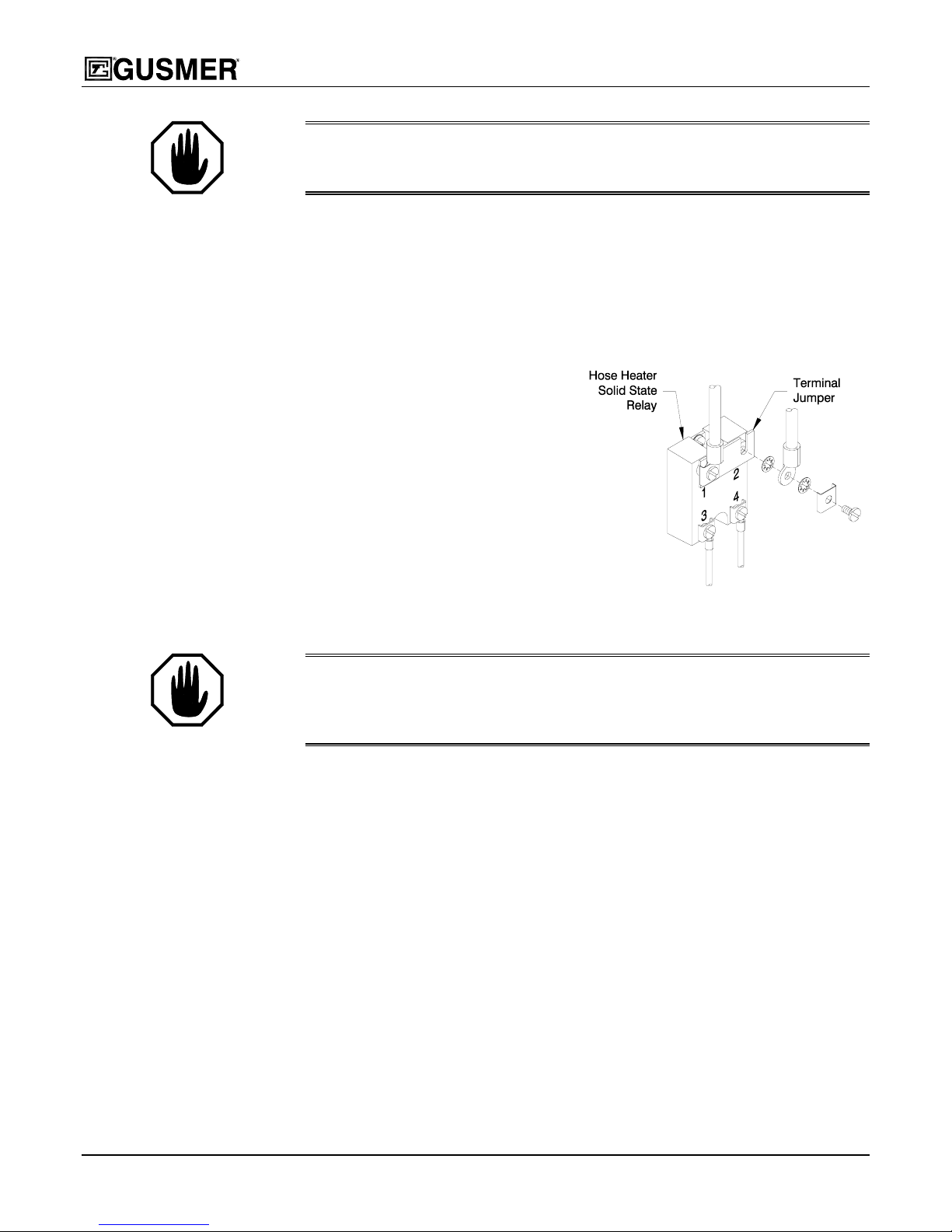
WARNING:
THE TERMINAL JUMPER MUST NEVER BE USED ON THE PRIMARY HEATER SOLID
STATE RELAY (SSR). THIS WILL RESULT IN COMPLETE LOSS OF CONTROL AND CAUSE DAMAGE
TO THE EQUIPMENT OR SERIOUS BODILY INJURY
c) Install the terminal jumper strip across terminals #1 and #2 on the Hose Heater
SSR.
d) Manual Hose Heat control requires the installation of a Hose Thermometer.
Insert the thermometer through the sponge so that the stem follows the twist of
.
the hoses and lies between the butyl inner hose and the outer sponge insulation.
This gives the most accurate temperature indication. The thermometer should
be located on the end of the hose nearest the gun in a position where the
operator can see it while spraying.
e) Maintaining hose temperature
now requires manual adjustment
of the Hose Heat Power Set.
Adjust the control clockwise to a
maximum of 50 Amps for initial
warm up and then adjust as
required to maintain the hose
temperature.
f) Restore electrical power, switch
ON the main switch and hose
heat circuit breaker and monitor
the thermometer for proper spray
temperature.
Figure 17. Terminal Jumper Strip
Installation
WARNING: D
HEAT SYSTEM. HOSE TEMPERATURE, AS INDICATED BY A PROPERLY INSTALLED HOSE
THERMOMETER
TO AVOID PERSONAL INJURY AND
O NOT ALLOW HOSE TO OVERHEAT DURING MANUAL CONTROL OF THE HOSE
, MUST NOT EXCEED 170
°
F (76° C). CLOSELY MONITOR HOSE TEMPERATURE
/OR DAMAGE TO PROPERTY.
6. TEMPERATURE SENSING UNIT (TSU)- Two conditions must be satisfied for
proper operation:
• The sensor must be functional.
• The signal must travel uninterrupted from the sensor to the control unit.
Unplug the TSU from its extension. Without undoing any chemical connections,
move the hose section with the TSU to the proportioning unit, plug the TSU directly
into the TSU extension harness, restore electrical power and energize the hose heat
circuit. If control is not restored, change the TSU. If control is restored,
systematically check each section of the TSU wire harness out to the gun.
7. PRIMARY HEAT AND HOSE HEAT TEMPERATURE SETTINGS- The purpose
of the hose heater is not to add heat but rather to maintain the temperature developed
by the primary heater. If indications are that the hose heater is not maintaining
temperature during flow, check that the primary heater and hose are set for the same
temperature or reduce the output.
8. LOW LINE VOLTAGE- The hose heat system operates at 220 Volts. Low line
voltage will significantly reduce power available and the heater will not perfo rm to
32 25942-1, Issue 4

Operating Manual Troubleshooting
its full capability at maximum hose length. A qualified electrician should determine
the secondary amperage of the hose heat circuit and adjust the tap setting as required
to achieve 45-50 amps.
9. REVERSED TSU CONNECTION- With the main switch primary heater and hose
heater circuit breakers OFF, change the sensor leads on terminal numbers 1 and 2.
10. SENSOR TYPE MISMATCHED- The preprogrammed controller operates with a
type “E” Thermocouple only. Ensure that only Gusmer supplied TSU is used.
11. HOSE HEAT TRANSFORMER TAP SETTING- The transformer voltage is
adjustable to accommodate between 35 ft. and 310 ft. of hose. Ensure that the
proper tap setting is selected for the hose length in use (see Hose Heat Power Pack
on page 15).
2/12/04 33

Model FF-2500 Proportioning Unit
MAINTENANCE
To realize full productivity and maximum service life from the FF-2500, it is necessary
to perform certain maintenance procedures daily or periodically.
WARNING:
PERFORMING THE WORK ON THE EQUIPMENT IS QUALIFIED TO DO SO. THIS INDIVIDUAL MUST
HAVE A WORKING KNOWLEDGE OF BASIC ELECTRICITY
FOLLOW ALL GENERALLY ACCEPTED SAFETY PRECAUTIONS USED WHEN WORKING WITH
HYDRAULICS
UNDERSTOOD THE APPLICABLE SECTIONS OF THIS MANUAL
PROTECTION APPROPRIATE TO THE TASK BEING UNDERTAKEN
WARNING:
MUST BE DONE WITH THE INCOMING POWER SWITCHED OFF AND LOCKED OUT AT THE SOURCE.
NY ELECTRICAL TROUBLESHOOTING REQUIRED BEYOND THE SCOPE OF THIS MANUAL MUST BE
A
DONE BY A QUALIFIED ELECTRICIAN
THE MAINTENANCE SECTION OF THIS MANUAL ASSUMES THAT THE INDIVIDUAL
, HYDRAULICS AND PNEUMATICS; MUST
, PNEUMATIC AND ELECTRO-MECHANICAL EQUIPMENT; MUST HAVE READ AND
; AND MUST WEAR PERSONAL
.
UNLESS OTHERWISE NOTED, ALL MAINTENANCE DESCRIBED IN THIS MANUAL
.
Proportioning Pumps
When the proportioning pumps are functioning properly, it is not unusual for a trace
amount of resin or isocyanate chemical to seep past the pump packing onto the pump
shaft. Maintain proper packing adjustment to minimize seepage. Routinely inspect the
shaft and wipe away any residue when the proportioner is turned off. Disassemble and
clean both proportioning pumps annually. Inspect the pistons and cylinders for mars or
scratches, which may cause leakage or damage to packings. As a preventive
maintenance precaution, Gusmer recommends replacement of the piston and cylinder
packings during the annual cleaning. (Refer to the Proportioning Pump Assembly section
of the Parts I.D. for reference.)
WARNING:
CYLINDER TOP HEX NUTS TO 10 FT/LBS.
Pump Bases
1. Perform the Daily Shut-down procedure and bleed all chemical pressures to zero.
2. Remove the valve cover using an adjustable wrench.
3. Remove the valve ball and inspect it for nicks and scratches. Replace as required.
34 25942-1, Issue 4
Disassemble and clean both pump bases annually as follows:
(Refer to the Pump Base Assembly section of the Parts I.D. for reference.)
AFTER REASSEMBLING OR SERVICING THE PROPORTIONING PUMPS, TORQUE THE
Inspect the valve cover o-ring and replace as required. Liberally coat the o-ring with
Lubriplate grease before installing the valve cover back into the pump base. Also,
check the chamfer around the cavity to ensure that there are no sharp edges, which
could damage the o-ring and prevent proper seal.

Operating Manual Maintenance
4. Inspect the face of the gasket for damage and replace as required. Reassemble the
Remove the ball seat with the special tool provided and inspect it for nicks and
scratches. Replace as required.
pump base.
Inlet Filter Screen
A filter screen in each proportioning pump traps solid matter that could adversely effect
the operation of the ball check valves in the pump base. Both screens should be
inspected daily and cleaned as required, as indicated in the Daily Start-up procedure.
The isocyanate component can crystallize from either moisture contamination or from
freezing. If the chemicals received are clean and if proper storage, transfer, and
operating procedures are followed, there should be minimal contamination of the
isocyanate screen. In practice though, it is good preventative maintenance to clean the
Remove and clean the filter screen as follows:
1. Switch OFF the pump switch and disconnect air from the proportioning unit. With
isocyanate screen daily.
IMPORTANT: Clean the isocyanate pump screen during the start-up procedure
. This will minimize moisture contamination problems by immed iately flushing
only
out any isocyanate residue at the start of the dispensing operation.
the gun removed, point the coupling block into an appropriate container, open the
corresponding manual valve of the side to be worked on and bleed chemical pressure
to ZERO.
2. Disconnect the transfer pump air supply and close the material inlet supply valve of
the appropriate proportioning pump. This prevents pumping of material with the
screen screw removed.
3. Place a rag beneath the filter base to catch the drain-off of chemical when removing
the screen screw.
4. Loosen the screen screw just enough to allow the material in the screen screw cavity
to drain out onto the rag.
5. Unthread the screen screw and remove it from the pump base.
6. Remove the retainer ring at the end of the screen screw and slide the screen from the
screen screw. Thoroughly flush the screen screw, the retainer ring, and the screen
with gun cleaner, and shake them dry. Inspect the screen to ensure the mesh is not
restricted. Replace as required.
7. Slide the screen on the screen screw and replace the retainer ring.
8. Flush the cavity in the pump base with gun cleaner and wipe the cavity clean, using
caution not to push foreign matter into the ball seat.
9. Install the screen screw assembly into the pump base by inserting the screen screw
with the threaded portion sliding along the top cavity. This prevents foreign matter
from entering into the ball seats. Thread the screen screw securely into the pump
base.
10. Reconnect the transfer pump air supply and open the material inlet supply valve.
Ensure there are no leaks and wipe the equipment clean.
2/12/04 35

Model FF-2500 Proportioning Unit
Isocyanate Pump Lubricant
To ensure that the pump lubricant will do its job, check its condition daily. Change the
lubricant before it becomes a gel, or when its color darkens as it becomes diluted with
isocyanate.
Gel formation is due to moisture absorption by the pump lubricant. The time interval
between changes due to gel formation will depend on environmental conditions in which
the equipment is operating.
To change the pump lubricant, proceed as follows:
1. Stop the proportioning unit with the pump yoke at the top of its stroke. Switch OFF
2. Remove the pump lubricant from the cup by dipping a dry rag into the cup to absorb
3. Fill the lubricant cup with fresh pump lubricant to about 3/4 inch below the top.
Discoloration of the lubricant is due to continual seepage of small amounts of isocyanate
past the pump packing during operation. However, if the packing within the isocyanate
pump is functioning properly, pump lubricant replacement due to discoloration should
not be more frequent than 3 or 4-week intervals.
the pump switch and disconnect the air from the proportioning unit.
the contaminated liquid. Wipe the cup and pump shaft clean. Remove any hardened
material from the shaft, taking care not to scratch the shaft.
36 25942-1, Issue 4

Operating Manual Instruction Manual Discrepancy Report
INSTRUCTION MANUAL DISCREPANCY REPORT
Field
Number
1 Date
2
3
4
5
6
7
Field Title Description
Name
IM Number
Issue Number
Date of Issue
Page Number
Discrepancy
Instructions:
Complete the above fields of the form by following the instructions listed on the reverse side of this sheet and mail to:
Gusmer Corporation
One Gusmer Drive PO Box 2055
Lakewood, NJ 08701
2/12/04 37

Model FF-2500 Proportioning Unit
Field
Number
1
2
3
4
5
6
7
Field Title Description
Date
Name
IM Number
Issue Number
Enter date report is submitted.
Enter name of person making report.
Enter the Part Number of the Instruction Manual from the title page.
Enter the Issue number of the Instruction Manual from the title page. If there is no
issue number, enter NONE.
Date of Issue
Enter the date of Issue of the Instruction Manual from the title page. If there is no
issue date, enter NONE.
Page Number
Discrepancy
Enter the page number containing the discrepancy.
Provide a brief description of discrepancy.
NOTE: You may send a marked copy of the page as an attachment to your
submittal.
38 25942-1, Issue 4
 Loading...