

Page 1
"Teamwork & Communication"
Model FF-1600
without Heat
Operating Manual
17942C-1
January 7, 2000
Issue 1
GUSMER CORPORATION
A Subsidiary of Gusmer Machinery Group, Inc.
One Gusmer Drive
Lakewood, New Jersey, USA 08701-8055
Toll Free 1-800-367-4767 (USA & Canada)
Phone: (732) 370-9000
Fax: (732) 905-8968
Copyright 2000, GUSMER CORPORATION
http://www.gusmer.com
®
®
NOTICE: This manual contains important information for your GUSMER equipment. Read and retain for future reference.
Page 2

Model FF-1600 with out Heat
NOTICE:
The equipment described in this technical manual must only be operated or serviced by properly trained individuals,
thoroughly familiar with the operating instructions and limitations of the eq uipment. For technical service, call your local
distributor. Call: 1-800-FOR-GSMR (1-800-367-4767) for the name and telephone number of your local distributor.
NOTICE:
All statements, information and data given herein are believed to be accurate and reliable but are presented without guarantee,
warranty or responsibility of any kind expressed o r implied. Sta tements or suggestions conce rning p ossible use of GUSME R
equipment are made without representation or warranty that any such use is free of patent infringement, and are not
recommendations to infringe any patent. The user should not assume that all safety measures are indicated or that other
measures may not be required.
2 17942C-1, Issue 1
Page 3

Operating Manual General Safety Information
CONTENTS
LIST OF FIGURES..........................................................................................................4
WARRANTY.....................................................................................................................5
GENERAL SAFETY INFORMATION..........................................................................6
CCEPTABLE EQUIPMENT USES....................................................................................... 6
A
O
PERATIONAL SAFETY PROCEDURES...............................................................................7
DESCRIPTION OF CONTROLS...................................................................................8
SPECIFICATIONS.........................................................................................................10
INITIAL MACHINE SET-UP.......................................................................................11
A
IR PURGE.....................................................................................................................13
NORMAL OPERATING PROCEDURES...................................................................14
AILY START-UP PROCEDURE .......................................................................................14
D
D
AILY SHUT-DOWN PROCEDURE................................................................................... 14
TROUBLESHOOTING PROCEDURES.....................................................................15
ENERAL INFORMATION................................................................................................15
G
P
ROPORTIONING SYSTEM...............................................................................................16
Solutions....................................................................................................................16
MAINTENANCE............................................................................................................19
UMP LUBE SYSTEM......................................................................................................19
P
I
NLET FILTER SCREEN....................................................................................................20
P
ROPORTIONING PUMPS.................................................................................................21
P
UMP BASES ..................................................................................................................21
NOTES.............................................................................................................................22
INSTRUCTION MANUAL DISCREPANCY REPORT............................................23
01/07/00 3
Page 4

Model FF-1600 with out Heat
LIST OF FIGURES
FIGURE 1 MODEL 17000C-1 PROPORTIONING UNIT............................................................ 8
F
IGURE 2 HOSE CONNECTION LOCATIONS ......................................................................... 12
F
IGURE 3 HOSE CONNECTION STEP (A)............................................................................. 12
F
IGURE 4 HOSE CONNECTION STEP (B)............................................................................. 12
F
IGURE 5 PUMP LUBE CUP LOCATION............................................................................... 13
F
IGURE 6. PROPORTIONING PUMP FEATURES................................................................... 16
4 17942C-1, Issue 1
Page 5

Operating Manual Contents
WARRANTY
Gusmer Corporation (Gusmer) provides a limited warranty to the original purchaser (Customer) of
Gusmer manufactured parts and equipment (Product) against any defects in material or
workmanship for a period of one year from the date of shipment from Gusmer facilities.
In the event Product is suspected to be defective in material or workmanship, it must be returned to
Gusmer, freight prepaid. If Product is found to be defective in material or workmanship, as
determined solely by Gusmer, Gusmer will issue full credit to Customer for the freight charges
incurred in returning the defective Product, and either credit will be issued for the replacement cost
of the Product or a replacement part will be forwarded no-charge, freight prepaid to Customer.
This warranty shall not apply to Product Gusmer finds to be defective resulting from: installation,
use, maintenance, or procedures not accomplished in accordance with our instructions; normal
wear; accident; negligence; alterations not authorized in writing by Gusmer; use of “look alike”
parts not manufactured or supplied by Gusmer; or Product used in conjunction with any other
manufacturer's pumping or proportioning equipment. Further, the terms and conditions of this
warranty shall not apply to services or repairs made to Product by any third party not authorized in
writing by Gusmer. For such Product, a written estimate will be submitted to Customer at a
nominal service charge, itemizing the cost for repair. Disposition of Product will be done in
accordance with the terms stated on the written estimate.
The warranty provisions applied to product that are not manufactured by Gusmer will be solely in
accordance with the warranty provided by the original manufacturer of the product.
GUSMER M AKES NO WARR ANTY WHATS OEV ER AS TO THE M ERCH AN TABI LITY OF,
OR SUITABILITY FOR, ITS PRODUCT TO PERFORM ANY PARTICULAR PURPOSE.
CREDIT FOR, OR REPLACEMENT OF, PRODUCT DEFECTIVE IN MATERIAL OR
WORKMANSHIP SHALL CONSTITUTE COMPLETE FULFILLMENT OF GUSMER
OBLIGATIONS TO CUSTOMER. NO OTHER WARRANTY, EXPRESSED OR IMPLIED ON
ANY PRODUCT IT MANUFACTURES AND/OR SELLS, WILL BE RECOGNIZED BY
GUSMER UNLESS SAID WARRANTY IS IN WRITING AND APPROVED BY AN OFFICER
OF GUSMER.
Under no circumstances shall Gusmer be liable for loss of prospective or speculative profits, or
special indirect, incidental or consequential damages. Further, Gusmer shall have no liability for
any expenses including, but not limited to personal injury or property damage resulting from failure
of performance of the product, use of the product, or application of the material dispensed through
the product. Any information provided by Gusmer that is based on data received from a third
source, or that pertains to product not manufactured by Gusmer, while believed to be accurate and
reliable, is presented without guarantee, warranty, or responsibility of any kind, expressed or
implied.
Gusmer through the sale, lease, or rental of Product in no way expresses or implies a license for the
use of, nor encourages the infringement of any patents or licenses.
To insure proper validation of your warranty, please co mplete the warranty card and return it to
Gusmer within two weeks of receipt of equipment.
Revised 11/12/98
01/07/00 5
Page 6

Model FF-1600 with out Heat
GENERAL SAFETY INFORMATION
It is necessary to understand and follow the instructions in this manual to insure proper
and safe operation of the equipment.
As with most mechanical equipment, certain safety precautions must be taken when the
equipment discussed in this manual is operated or serviced. Severe bodily injury or
damage to equipment and property may result if the instructions and precautions listed
throughout this manual are not followed.
Needless to say, sufficient guidelines cannot be developed to eliminate the need for good
common sense in the use and servicing of this equipment, and in the use and application
of the products, this equipment has been designed to process. Users of this equipment
must therefore, make their own determination as to the suitability of the information
contained in this manual to their specific operation and requirements. There should be no
assumption made that the safety measures and instructions contained herein are allinclusive, and that other safety measures may not be required for specific use or
application.
The following safety guidelines are generally applicable to the safe and efficient use of
the equipment.
Acceptable Equipment Uses
The equipment is designed for the dispensing of polyurethane foams, two-component
coating systems, and some two-component epoxy systems, specifically polyureas. Under
no circumstances should any acid or corrosive chemicals be used in the unit. Consult
GUSMER if there is any doubt about the compatibility of the chemical system to be used
in this equipment.
Any use of this equipment other than as indicated above constitutes misuse unless express
written approval is obtained from GUSMER.
6 17942C-1, Issue 1
Page 7
Operating Manual General Safety Information
Operational Safety Procedures
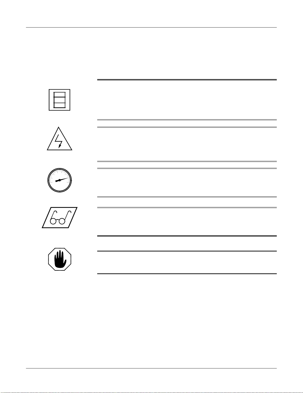
This safety information will not be repeated in the text of this manual. The symb ols
pertaining to this information will ap pear where appropriate to alert the operator to
potential hazards.
Solvents and Chemicals
High Voltage
High Pressure
Personal Protective
Equipment
WARNING: T
OPERATOR TO CERTAIN HAZARDS. ADEQUATE PERSONAL PROTECTIVE MEASURES MUST
BETAKEN SO AS TO AVOID EXCEEDING THE
PRODUCTS BEING USED
HE SOVENTS AND CHEMICAL USED WITH THIS EQUIPMENT EXPOSE THE
THRESHOLD LIMIT VALUE (TLV) OF THE
, AS ESTABLISHED BY THE OCCUPATIONAL SAFETY AND HEALTH
ADMINISTRATION (OSHA) OR OTHER QUALIFIED AGENCY. INFORMATION CONCERNING
PERSONAL PROTECTION AND PROPER HANDLING FROM THE SUPPLIER OF SUCH CHEMICALS
WARNING:
THE ELECTRIC CONSOLES OR OTHERWISE SERVICE THIS EQUIPMENT AND/OR EQUIPMENT USED
WITH IT BEFORE SWITCHING OFF THE MAIN POWER DISCONNECT AND INTERRUPTING SUPPLY
VOLTAGE AT THE SOURCE
A QUALIFIED ELECTRICIAN
WARNING:
COMPONENTS CAPABLE OF PRODUCING UP TO 3500 PSI. TO AVOID SERIOUS BODILY INJURY
FROM HYDRAULIC INJECTION OF FLUID
SERVICE HYDRAULIC COMPONENTS WITHOUT BLEEDING ALL PRESSURES TO ZERO
WARNING:
WHEN OPERATING, SERVICING, OR BEING PRESENT IN THE OPERATIONAL ZONE OF THIS
EQUIPMENT
SAFETY SHOES, AND RESPIRATORY EQUIPMENT AS REQUIRED.
TO PREVENT SERIOUS BODILY INJURY FROM ELECTRICAL SHOCK, NEVER OPEN
. THE ELECTRICAL SERVICE MUST BE INSTALLED AND MAINTAINED BY
.
THIS EQUIPMENT HAS OR IS USED WITH EQUIPMENT THAT HAS HYDRAULIC
, NEVER OPEN ANY HYDRAULIC CONNECTIONS OR
.
TO AVOID SERIOUS BODILY INJURY, PROPER PROTECTIVE GEAR MUST BE WORN
. THIS INCLUDES, BUT IS NOT LIMITED TO, EYE AND FACE PROTECTION, GLOVES,
.
WARNING: F
PERSONAL INJURY AND/OR DAMAGE TO THE EQUIPMENT FROM ONE OR MORE OF THE ABOVE
LISTED HAZARDS
AILURE TO READ AND FOLLOW THIS SAFETY INFORMATION MAY RESULT IN
Warning
01/07/00 7
Page 8
Model FF-1600 with out Heat
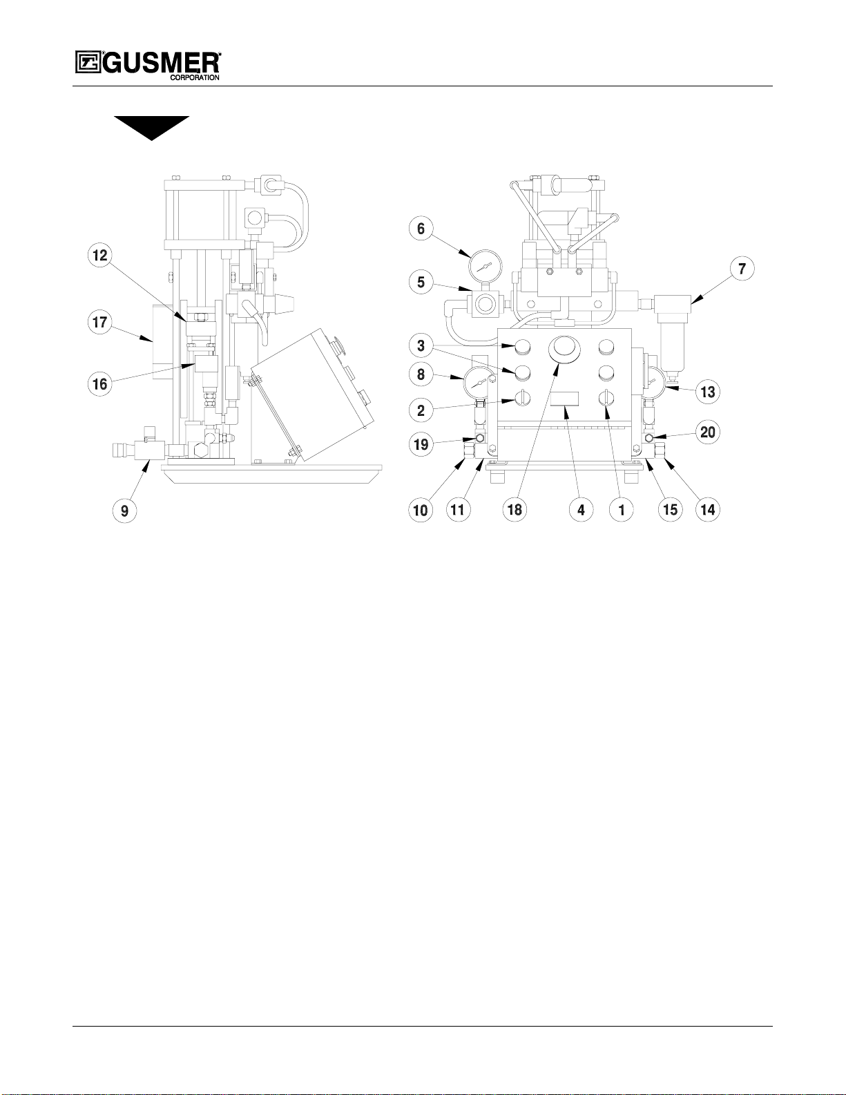
DESCRIPTION OF CONTROLS
Figure 1 Model 17000C-1 Proportioning Unit
1. MAIN SWITCH- Controls power to all circuits.
• OFF- Main Power is off.
• POWER- Turn the Main Switch to this position. To supply Main Power to the
Console. A White pilot light will indicate this.
• ON- Turn the Main Switch to this position and allow it to return to the POWER
position to enable the Console Controls. An Amber pilot light will indicate this.
2. PUMP SWITCH- Controls operation of the air drive system.
• OFF- Air Drive system is off.
• NORMAL- Must be in this position for the Proportioning Pumps to operate
• RETRACT- Use this position for shutdown. It will stop the air mo tor at the
bottom of the stroke with the Proportioning Pumps in the retracted position
3. PUMP DIRECTIONAL INDICATOR LIGHTS (Amber)- Indicate the direction
the Proportioning Pump is traveling. Both lights will be off when the pump switch is
OFF or when either Proportioning Pump exceeds its designed operating pressure
limit.
4. COUNTER- Records the cycle count of the Proportioning Pumps. One cycle count
equals two (2) strokes (one in each direction).
5. AIR PRESSURE REGULATOR- Controls the speed of the air motor on the up and
downstroke.
8 17942C-1, Issue 1
Page 9

Operating Manual Initial Machine Set-up
6. AIR PRESSURE GAUGE- Displays the air pressure in the air drive system during
the up and downstroke.
7. MAIN AIR FILTER- Filters the system air supply. (3/8 NPT Female)
8. ISOCYANATE PRESSURE GAUGE- Displays the pump out put pressure in the
Isocyanate proportioning system.
9. A-INLET SUPPLY VALVE (R on other side)
10. A-INLET FILTER SCREEN
11. A-PUMP BASE
12. A-PACKING NUT, LUBE CUP (R on other side)
13. RESIN PRESSURE GAUGE- Displays the pump out put pressure in the resin
proportioning system.
14. R-INLET FILTER SCREEN
15. R-PUMP BASE
16. PRESSURE LIMIT SWITCH- Factory set to turn off the air drive system when the
Proportioning Pump exceeds the designed operating pressure limit. (A side shown, R
on other side
17. AIR MOTOR REVERSING SWITCH- Energizes and de-energizes the air valve
coils to reverse direction.
18. EMERGENCY STOP BUTTON- Disables the Console Controls when engaged.
Amber Control Power pilot light will remain off until the button has been reset and
the Console Controls re-enabled. The White Lamp will remain illuminated.
(Twist to reset)
19. ISOCYANATE OUTLET- 1/2 FPT (Swivel) Fitting
20. RESIN OUTLET- 3/4 FPT (Swivel) Fitting
01/07/00 9
Page 10

SPECIFICATIONS
Model FF-1600 with out Heat
Air
Electric
Maximum Output
Maximum Pr essure
Viscosity
26 scfm @100 psi (12 liters/sec @7 bars)
2 amps @ 110 volts, 50/60 Hertz single phase, AC.
16 lbs/min. (7.25 kg/min)
1600 psi (108 bars) @ 100 psi Air
25-3000 cps (25-3000 cps)
10 17942C-1, Issue 1
Page 11

Operating Manual Initial Machine Set-up
INITIAL MACHINE SET-UP
WARNING: PROPER PROTECTIVE GEAR AS SPECIFIED BY THE CHEMICAL AND SOLVENT
SUPPLIER MUST BE WORN WHEN SERVICING OR OPERATING THIS EQUIPMENT. IT INCLUDES
BUT IS NOT LIMITED TO GLOVES
GENERAL SAFETY INFORMATION SECTION OF THIS MANUAL.
THE
The following parts are included with the unit and are required for set-up:
• Tape
• Air Hose Assembly
• (2) Swivel Unions
WARNING: THE PROPORTIONING UNIT ELECTRIC SERVICE MUST BE INSTALLED BY A
QUALIFIED ELECTRICIAN ACCORDING TO NATIONAL ELECTRIC CODE AND ALL APPLICABLE
LOCAL CODES
.
IMPORTANT: Before for proceeding be sure that the Main Power Supply is
disconnected.
, EYE PROTECTION, AND RESPIRATORY PROTECTION. REFER TO
To obtain the best possible
NOTE:
results, the power source must be
capable of meeting the electrical
requirements specified on the
nameplate and must be provided
with a dedicated fuse disconnect.
1. Connect the Main Power Cord to the electrical console using wire size #10 or larger
(not supplied).
a) Feed the power cor d through the strain relief in the ba ck of the console and
connect the power leads to L1 and N.
b) Connect the ground wire to the gro und lug.
2. Setup the supply and air control system as required.
a) Connect the Resin supply to the R-Inlet 3/4 FPT (Swivel) Fitting.
b) Connect the Isocyanate supply to the A-Inlet 1/2 FPT (Swivel) Fitting.
c) Connect the air supply to the1/4 MPT nipple on the Transfer pump.
Remove the cap to access it.
3. Connect the Main Air Supply to the P r oportioning Unit. The main air inlet fitting is
a 3/8 MPT nipple.
IMPORTANT: The Main Air Supply must be clean and free of contaminants
A minimum of 3/8 inch inside diameter air line (not supplied) should be used to
deliver the air supply to the proportioning unit.
Fitting a main air shutoff valve to the Proportioning Unit is recommended.
4. Connect the Hose Assemblies to the Proportioning Unit. See Figure 2 Hose
Connection Locations.
IMPORTANT: The resin hoses are color-coded blue and the Isocyanate hoses are
color- coded red for easy identification. In addition, the resin and Isocyanate hose
fittings are different sizes, making it virtually impossible to improperly connect the
hoses
01/07/00 11
Page 12

The hoses are Connected end to
NOTE
end during shipment to protect
them from moisture intrusion Do
not separate the hoses until they
are ready for coupling to the
proportioning unit.
Model FF-1600 with out Heat
Figure 2 Hose Connection Locations
5. Connect the Hose Assemblies together as follows. See Figure 3 and Figure 4.
:
IMPORTANT: It is important to make proper hose connections. The connection
points are a potential source of chemical and airs leaks and are susceptible to
damage from scuffing and snagging on abrasive surfaces. A liberal amount of duct
tape can be used in this area to make the bundle as compact as possible. Gusmer
recommends the installing of the optional scuff jacket to protect the hose insulation
from damage
a) Lay out Hose
assemblies as shown.
b) Connect Hose
Assemblies as shown
taking care not to
cross thread or overtighten the fittings,
there by assuring a
leak proof chemical
connection.
Figure 3 Hose Connection Step (A)
Figure 4 Hose Connection Step (B)
*** Repeat Step 5 for adding additional hoses. ***
12 17942C-1, Issue 1
Page 13

Operating Manual Initial Machine Set-up
6. Connect the air hose adapter between the Proportioning Unit and hoses.
7. Connect the coupling block to the gun hose and see t hat the manual valves are closed.
Air Purge
Prior to operation, it is necessary to purge the entire system of air and mineral oil left over
from the functional testing of the equipment.
To purge the machine proceed as follows:
1. Turn on the main air supply.
2. Pressurize the Transfer Pumps and open the A and R-Inlet Supply Valves. It is a
good practice at this point to check for material leaks
3. Turn the Main Switch to ON. The White pilot light should come on followed by the
Amber pilot light
4. Adjust the Air Pressure Regulator to zero. (Full counter clockwise).
5. Switch the Pump Switch to NORMAL.
Properly discard both
NOTE:
materials in accordance
with applicable
environmental regulations.
6. Remove the gun from the coupling block
7. Adjust both the Air Pressure
Regulators clockwise until the
pumps begin to move
(approximately 15-psi air pressure).
When the pumps reach the top of
their stroke, turn the pump switch to
OFF. This will facilitate easy access
to the pump lube cup on the
Isocyanate pump. Fill the lube cup
to about 1/4-inch from the top with
pump lube. (See Figure 5)
Figure 5 Pump Lube Cup Location
8. With the coup l ing block held over separate containers, open both manual valves and
turn ON pump switch. Allow both materials to flow out of the coupling block
simultaneously until all spitting of air stops and all traces of residual material have
disappeared and a solid flow of each material is seen.
9. Switch the Pump Switch to OFF.
10. Close both manual valves and wipe clean any residual material from the coupling
block.
11. Mount the gun to the co upling block.
01/07/00 13
Page 14

Model FF-1600 with out Heat
NORMAL OPERATING PROCEDURES
Daily Start-up Procedure
1. Check the condition of the Isocyanate lube cup and service as required.
2. Adjust the packing. The packing nut on the Proportioning Unit is adjustable and will
require tightening when the pump lube is changed.
3. Check the inlet screens and service as required.
4. Determine that the chemical system is at the proper temperature as recommended by
the chemical supplier and that the moisture protection system, is in working order.
5. Turn on the Main Air Supply to the Transfer Pump.
6. Pressurize the Transfer Pumps and open both A and R-Inlet Supply Valves.
7. Turn ON the Main Switch. The White pilot light should come on followed by the
Amber pilot light.
The standard size 60 pumps have
NOTE:
a material pressure to air pressure
ratio of approximately 16 to 1.
Daily Shut-Down Procedure
8. Set the Air Pressure Regulator as required.
9. Set the Pump Switch to NORMAL. One of the amber Pump Directional Indicator
Lights should be ON and the Proportioning Pumps should move a short distance and
pressurize.
10. Connect air to the gun, open the manual valves, and test spray while observing the
chemical pressure gauges on both the up and down strokes. Readjust the regulator as
required.
1. Set the Pump Switch to the RETRACT position.
2. Trigger the gun off target until the Proportioning Pumps stop in the retracted position
and the Proportioning Pumps pressures bleed off to approximately 500 psi.
IMPORTANT: It is not a good practice to bleed the pressure to zero. Some pressure
is required to keep the packings operating normally and prevent weepage during
shutdown.
3. Switch OFF the Main Switch.
4. Close both Inlet Ball Valves.
5. Shutdown the chemical supply system as required.
6. Close both manual va l ves on the Gun. Shutdown and service the gun as needed.
7. Turn OFF the Main Air Supply.
14 17942C-1, Issue 1
Page 15

Operating Manual Maintenance
TROUBLESHOOTING PROCEDURES
General Information
When properly maintained and operated, GUSMER equipment will provide long and
faithful service. However, occasional problems will arise which must be resolved before
operation can continue. The purpose of this section is to give an explanation of what
problems may arise, how to detect them, and how to resolve them.
This manual is written to give the operator a general overview of the operation of the
equipment, therefore it is imperative that before any trouble shooting pro cess b e gins, the
operators have read and understood the applicable portions of this manual.
Training schools held on a regular basis further develop the necessary knowledge for
proper operation, maintenance and trouble shooting of GUSMER equipment. These
schools give concentrated training on the equipment and help to develop an operator into
a competent Certified Gusmer Technician.
GUSMER maintains a competent staff of Technical Representatives and authorized
Distributors who can resolve almost any problem you may encounter with GUSMER
equipment. Feel free to call on these people for assistance when you need it.
WARNING: THE TROUBLE SHOOTING SECTION OF THIS MANUAL AS SUMES THAT THE
INDIVIDUAL PERFORMING THE WORK ON THE EQUIPMENT IS QUALIFIED TO DO SO. THIS
INDIVIDUAL MUST HAVE A WORKING KNOWLEDGE OF BASIC HYDRAULICS AND PNEUMATICS
MUST FOLLOW ALL GENERALLY ACCEPTED SAFETY PRECAUTIONS USED WHEN WORKING WITH
HYDRAULICS
THE APPLICABLE SECTIONS OF THIS MANUAL
APPROPRIATE TO THE TASK BEING UNDERTAKEN
, PNEUMATIC AND ELECTRICAL EQUIPMENT; MUST HAVE READ AND UNDERSTOOD
; AND MUST WEAR PERSONAL PROTECTION
.
;
WARNING: ALL ELECTRICAL TROUBLE SHOOTING DESCRIBED IN THIS MANUAL MUST BE
DONE WITH POWER OFF TO AVOID SEVERE BODILY INJURY FROM ELECTRICAL SHOCK. THIS
, THAT IN ADDITION TO ALL CIRCUIT BREAKERS "OFF," DISCONNECT THE MAIN POWER
MEANS
AT THE SOURCE
OPERATION OF GUSMER EQUIPMENT MUST DO ANY ELECTRICAL TROUBLE SHOOTING
REQUIRED BEYOND THE SCOPE OF THIS MANUAL
. A QUALIFIED ELECTRONIC TECHNICIAN, THOROUGHLY FAMILIAR WITH THE
.
01/07/00 15
Page 16

Model FF-1600 with out Heat
Proportioning System
Figure 6. Proportioning Pump Features
To avoid unnecessary repairs, try the recommended solutions in the order given for each
problem. Before assuming there is a problem, determine that all circuit breakers,
switches, and controls are properly set.
Problems Solutions
Proportioning pump does not hold pressure when stalled. 1
Pressure unbalance between pumps. 2,3,4
Cavitation in the Proportioning Pump. 2,3,4
Failure of the pump to reverse. 7,8
Pumps do not move and the directional indicator lights are out. 5,6,7
Pump movement is erratic. 8
Unequal pressure or speed on the upstroke ve rsus the downstroke 9
SOLUTIONS
1. Determine which inlet or discharge valve is leaking. If the pump (A or R) is losing
pressure on the upstroke then check the discharge valve of the respective pump. If
the pump is losing pressure on the downstroke then check the inlet valve of the
respective pump.
a) Close the Inlet Supply Valve and de-pressurize the Transfer Pump.
b) De-pressurize the Proportioning Pump.
c) Remove the appropriate valve cover and, using the magnet from the
toolbox, remove the valve ball.
d) Flush and wipe clean the valve ball and ball seat of all residual material.
Inspect these parts for damage.
16 17942C-1, Issue 1
Page 17

Operating Manual Maintenance
e) In most cases, the cause of the leaking valve is a particle of foreign
material preventing the ball from seating properly. If cleaning the ball
and seat does not resolve the problem, then replace the valve ball and or
pump base.
2. Trouble shooting this problem requires that two points be determined:
First- Which chemical did not reach the gun?
Second- Why did that chemical fail to get there?
Determine the first point by checking t he color of the material exiting the gun. Foam
systems are usually a combination of light and dark material. Therefore, by
observing the color of the liquid exiting t he gun, one can determine which material is
missing.
The second point either is due to a restriction in the gun or because the Proportioning
Pump did not perform properly in pumping it’s designed volume.
This is determined by checking the chemical pressure gauges on the Proportioning
Unit. Focus on the pressure gauge corresponding to the missing chemical.
Assume that the R-component is not reaching the gun. If the resin pressure gauge is
considerably lower than normal, the problem is the pump. If the resin gauge is
considerably higher than normal the problem is usually in the gun and must be
resolved by referring to the gun manua l.
3. CAVITATION is the formation of a partial vacuum or void within the pump cylinder
during the fill/upstroke stroke.
It is actually a “short fill” since the fill chamber does not fill completely with liquid
when the pump reverses to start the discharge/down stroke. This “short fill” occurs
when the Proportioning Pump demands a greater volume of material during its fill
stroke than can be supplied.
The most common causes of cavitation are as follows:
a) The Transfer Pump can not handle the supply requirement. A
GUSMER 2:1 Transfer Pump is recommended for use with this
Proportioning Unit. Also recommended is a minimum of 3/4” diameter
supply hose, as short as practical.
b) The chemical is too viscous (thick) to pump properly. The
recommended supply temperature is 65° F, to 75° F. At temperatures
below 65° F, the material thickens and becomes increasingly harder to
pump.
c) Inlet filter screen is restricted. Service as described in the Maintenance
section of this manual.
WARNING: THE DESIGN OF THIS PROPORTIONING UNIT ALLOWS IT TO OPERATE AT
PRESSURES UP TO 1600 PSI. EXTREME CAUTION MUST BE EXERCIZED BEFORE OPENING ANY
HYDRAULIC CONNECTIONS OR SERVICING THE PUMP OR PUMP BASE
BLEED OFF THE PRESSURE IN BOTH THE SUPPLY AND DELIVERY SIDES OF THE PUMP TO ZERO
TO AVOID SERIOUS BODILY INJURY FROM FLUID INJECTION
CONTAINING CHEMICALS WITHOUT WEARING APPROVED SAFETY GLASSES AND PROTECTIVE
GLOVES TO PREVENT PROLONGED SKIN CONTACT
.
. NEVER SERVICE COMPONENTS
. THE OPERATOR MUST
01/07/00 17
Page 18

Model FF-1600 with out Heat
4. LEAKING INLET CHECK VALVE - An inlet check valve and/or leaking seat that
does not properly seal will permit some of the proportioned material to flow back
towards the supply drum. When this ha ppens the proper volume of material will not
pump during the discharge str oke and an off-ratio condition will result.
5. A 2200-psi pressure limit switch protects each Proportioning Pump. Upon reaching
this pressure, the switch automatically removes power from both directional valves
causing the pump to stall. When the power is removed, both Directional Indicator
Lights will go out, this indicates there ha s been an over-pressure shutdown.
This is not a lockout type of system and when the pressure bleeds off to
approximately 200 psi, the Proportioning Pumps will be restored to normal
operation; however, the cause of the over-pressure should be determined first and
then corrected.
The most likely causes of over-pressure are:
a) Restriction in the gun
b) Pump cavitation
c) Air pressure set too high
6. CONTROL TRANSFORMER FUSE - With the power OFF, open the electric
console, and remove the control transformer fuse. Check it for continuity or simply
replace it.
WARNING: REPLACE THE FUSE WITH ONE OF THE SAME RATING. A SUBSTITUTE MAY
DAMAGE THE EQUIPMENT AND WOULD CREATE A POTENTIAL SOURCE OF INJURY TO THE
OPERATOR
.
WARNING: BEFORE PERFORMING THESE TROUBLE SHOOTING PROCEDURES DETERMINE
THAT ALL CIRCUIT BREAKERS ARE OFF AND MAIN POWER IS DISCONNECTED AT THE SOURCE TO
AVOID SEVERE BODILY INJURY FROM ELECTRICAL SHOCK
CONSOLE WITH THE POWER ON
. DO NOT ENTER THE ELECTRICAL
7. REVERSING SWITCH - In order for the Proportioning Unit to switch direction or
reverse, the ends of a slot machined in the rear leg of the pump yoke must contact the
arm of the switch lever. This contact causes the switch lever to activate on the
reversing switch, which energizes one air valve coil and de-energizes the other. A
problem arises when the yoke fails to contact the switch lever or when the spool in
the air valve fails to shift after its coil activates.
Typically, something physically prevents the yoke from traveling its full stroke. In
this case physically check and correct it. It may also be the result of the air pressure
set to a point where the total resistance downstream of the air motor is such that the
air motor cannot pump against it. Correct this by simply increasing the air pressure.
8. ROLLER BEARINGS- Occasionally replacing the roller bearing is necessary if they
become clogged with dirt or Isocyanate and seize.
9. UPSTROKE REGULATOR- During the upstroke, both Proportioning Pumps will be
on the fill stroke and will receive a boost from the supply pump pressure. Adjust the
upstroke regulator so the Proportioning Pump speeds are equal on both strokes.
18 17942C-1, Issue 1
Page 19

Operating Manual Maintenance
MAINTENANCE
To realize the full productivity of the Proportioning Unit it is necessary to perform
maintenance on a daily or periodic basis.
WARNING: WHENEVER WORKING ON THE EQUIPMENT, WEAR EYE AND SKIN PROTECTION TO
GUARD AGAINST EXPOSURE TO THE CHEMICALS AND SOLVENTS IN USE. ALWAYS WORK IN A
WELL VENTILATED AREA TO PREVENT EXPOSURE TO HARMFUL FUMES AND VAPORS
I
NFORMATION CONCERNING THE TOXICITY AND PROPER HANDLING PROCEDURES OF YOUR
CHEMICALS AND SOLVENTS IS AVAILABLE FROM YOUR SUPPLIER
U
NLESS OTHERWISE SPECIFIED, SWITCH OFF ALL CIRCUIT BREAKERS AND DISCONNECT THE
MAIN POWER AT THE SOURCE TO AVOID SEVERE BODILY INJURY FROM ELECTRICAL SHOCK
NOT ENTER THE ELECTRICAL CONSOLE WITH POWER ON
P
RESSURES UP TO 1600 PSI EXIST IN THE HYDRAULIC COMPONENTS. BEFORE OPENING ANY
HYDRAULIC CONNECTIONS OR SERVICING HYDRAULIC COMPONENTS USE EXTREME CAUTION TO
INSURE BLEEDING OF ALL PRESSURES TO ZERO TO AVOID SERIOUS BODILY INJURY FROM FLUID
INJECTION
.
.
.
.
. DO
Pump Lube System
Check the condition of the pump DAILY, to insure that lube will do its job. Change the
Pump Lube before it becomes a gel, turns cloudy, or becomes the same color as the
Isocyanate.
The gel formation is due to moisture absorption by the pump lube. The time interval
between changes due to gel formation depends entirely upon the environment in which the
equipment is operating.
Discoloration of the Pump Lube is inevitable due to the continual weepage of Isocyanate
during pump operation. However, if the packing within the Isocyanate pump is
functioning properly, Pump Lube replacement due to discoloration should not be more
frequent than 3 to 4 week intervals.
To change the Pump Lube proceed as fo llows:
1. Stop the Proportioning Unit with the pump yoke at the top reverse. Switch OFF the
pump switch and disconnect the air from the Proportioning Unit.
2. Remove the pump lube from the lube cup by dipping a dry rag into the cup to absorb
the contaminated liquid. Wipe the cup and pump shaft clean. Remove any hardened
material from the shaft taking care not to scratch the shaft.
3. Fill the lube cup with Pump Lube to about 3/4 inch below the top.
01/07/00 19
Page 20

Model FF-1600 with out Heat
Inlet Filter Screen
A filter screen in each Proportioning Pump filters out solid matter that could adversely
effect the operation of the valve balls in the pump base. You will note that the Daily
Start-up Procedure indicates these screens should be inspected daily.
For the first week or so of operation, you should clean both pump screens on a daily basis.
However, you will probably find that the resin pump screen rema ins clean and that weekly
checking of this part will be sufficient.
The Isocyanate pump screen is another matter. The Isocyanate component can crystallize
from either moisture contamination or from freezing. If you follow proper storage,
transfer, and operating procedures, and if the chemicals you receive, are clean, you should
have little problem with the Isocyanate screen. In practice though, findings suggest that
daily cleaning of the Isocyanate screen is sound preventative maintenance. It is important
not to clean the Isocyanate pump screen during the shutdown operation. This is because
the cleaning of the screen exposes it and its related parts to moisture and solvent, which
can cause the Isocyanate to crystallize. By accomplishing the cleaning operation during
the Start-up Procedure, contamination problems will flush out immediately when
dispensing commences.
Removal and cleaning of the filter screen is accomplished as follows:
1. Switch OFF the Pump Switch and disconnect air from the Proportioning Unit. Bleed
chemical pressure from the side you are working on by opening the corresponding
manual valve on the coupling block while pointing it into an appropriate container.
2. Close the material supply valve at the inlet of the appropriate Proportioning Pump.
This prevents the pumping of material with the screen screw removed.
3. Place a cup, in the space provided beneath the filter base to catch the chemical, which
will drain-off upon removing the screen screw.
4. Loosen the screen screw sufficiently to allow the material in the screen screw cavity
to drain out into the cup.
Remove the screen screw from the pump base by continuing to unthread it until it
comes loose.
5. Remove the retainer ring at the end of the screen screw and slide the screen from the
screen screw. Thoroughly flush the screen screw, the retainer ring, and the screen
with the gun cleaner, and shake them dry. Inspect the screen to insure the mesh is not
restricted. Replace as required.
6. Slide the screen on the screen screw and replace the retainer ring.
7. Flush the cavity in the pump base with gun cleaner and wipe the cavit y cle an using
caution not to push foreign matter into the ball seat.
8. Install the screen screw assembly into the pump base by inserting the screen screw
with the threaded portion sliding along the top cavity. This prevents pushing foreign
matter into the ball seats.
9. Open the material supply valve; insure there are no leaks and wipe the equipment
clean.
20 17942C-1, Issue 1
Page 21

Operating Manual Maintenance
Proportioning Pumps
Disassemble and clean both Proportioning Pumps annually. Inspect the pistons and
cylinders for mars or scratches, which may cause leakage or damage to the packings, and
replace as necessary. As a preventative maintenance precaution, replace the piston and
cylinder packings on an annual basis.
Pump Bases
1. Completely depressurize the system.
2. Remove the valve cover using an adjustable wrench.
Inspect the valve cover o-ring and replace as required. It is good practice to liberally
coat the o-ring with grease before inserting the valve cover back into the pump base.
Also, check the chamfer around the cavity to insure that there are no sharp edges,
which could damage the o-ring and prevent proper seal.
3. Remove the valve ball and inspect it for nicks and scratches. Replace as required.
Remove the ball seat with the special tool provided and inspect it for nicks and
scratches. Replace as required
4. Inspect the face of the gasket for damage and replace as required. Reassemble the
pump base.
01/07/00 21
Page 22

NOTES
Model FF-1600 with out Heat
22 17942C-1, Issue 1
Page 23

Operating Manual Instruction Manual Discrepancy Report
INSTRUCTION MANUAL DISCREPANCY REPORT
Field
Number
1
2
3
4
5
6
7
Field Title Description
Date
Name
IM Number
Issue Number
Date of Issue
Page Number
Discrepancy
Instructions:
Complete the above fields of the form by following the instructions listed on the reverse side of this sheet and mail to:
Gusmer Corporation
One Gusmer Drive PO Box 2055
Lakewood, NJ 08701
01/07/00 23
Page 24

Model FF-1600 with out Heat
Field
Number
1
2
3
4
5
6
7
Field Title Description
Date
Name
IM Number
Issue Number
Enter date report is submitted.
Enter name of person making report.
Enter the Part Number of the Instruction Manual from the title page.
Enter the Issue number of the Instruction Manual from the title page. If there is no
issue number enter NONE.
Date of Issue
Enter the date of Issue of the Instruction Manual from the title page. If there is no
issue date, enter NONE.
Page Number
Discrepancy
Enter the page number containing the discrepa ncy
Provide a brief description of discrepancy
NOTE: You may send a marked copy of the page as an attachment to yo ur
submittal.
24 17942C-1, Issue 1
 Loading...