

Guru Home Systems GU-HB-201-R1 Installation Manual

GURU Hub Base Unit V1
Installation Guide
GU - HB - 201 - R1

Thanks for choosing Guru!
The Guru Hub provides residents with a simple way to control
their own energy use and allows housing managers to flexibly
manage debt risk.
The Guru Hub works with a range of utilities, including heating,
cold water and private wire electricity networks. The Hub can
read up to five meters and control up to three actuators (such as
valves and contactors).
The Guru Hub has been designed with extensive input from
building services professionals. We aim to make the installation
process as simple as possible.
For technical support, please call us on 0207 042 9270
or email at info@fontenergy.com
We strive to continuously improve our products. If you have any
feedback on the installation process or ideas of how to improve it,
please let us know!

3
Table of contents
Before you begin
Specifications
Connected devices
Testing & approvals
Terminals & cable specification
Installation of GURU Base Unit
Supplies required (not included)
Safety
Choosing a location
Attaching the Base Unit to the wall
Wiring the Base Unit
Wiring connections in Compartment A
Wiring connections in Compartment B
Sample wiring diagrams
Installation of Guru Top Unit
Safety
Connecting the Top Unit to the Base Unit
Fixing the Top Unit in the oset position
Attaching the Top Unit to the Base Unit
Cleaning
4
5
6
7
7
9
9
9
10
11
12
13
14
14
15
15
15
16
17
18
4
The Guru Hub comprises two sections:
1. The Base Unit – to be mounted to the wall inside the dwelling
and connected to mains input, control devices and data
inputs.
2. The Top Unit – to be connected to the Base Unit.
The Base Unit is designed for installation at second fix. It can
be installed, with covers in place, and safely left until the Top
Unit is installed. The Top Unit can be installed any time after the
Base Unit, but is intended to be installed once other trades have
completed their work and there is less risk of damage to the Top
Unit’s delicate components.
For information on how to operate the GURU Smart Energy Hub,
please read the User Guide.
Please read this entire installation manual before starting
installation. Please note that protection provided by the
equipment may be impaired if used in a manner other than as
specified in this installation guide.
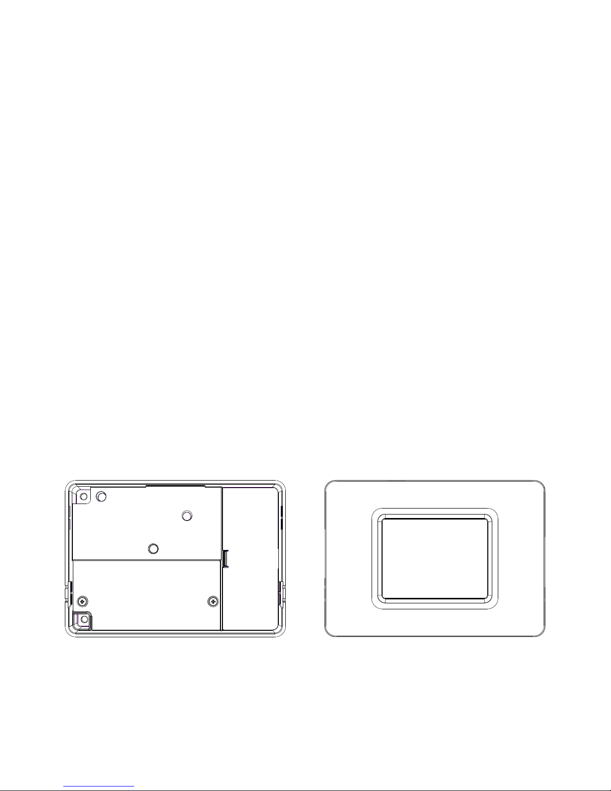
Figure 1. Base unit Figure 2. Top unit
Before you begin

5
Dimensions (W x H x D): 150 x 105 x 44 mm (Base Unit only: 150 x
105 x 35 mm)
Display type: 3.5” RGB TFT with touch screen
Power consumption: < 2W average (excluding load on relays)
Power supply: 230VAC 50Hz 5A max current
Real-time clock battery: CR2032 lithium coin cell
Radio: 2.4 GHz mesh network
Operating temperature: 0° to 40°C
Storage temperature: -5° to 50°C
Operating relative humidity: 5% to 90%
Ingress rating: IP43 (with top unit installed or all base unit covers
in place)
Service life: 10 years
Specifications

6
The Guru Hub has the following interfaces for connecting external
devices:
1 x M-Bus master node, which can read up to five M-Bus slave
devices such as heat or electricity meters. For a list of compatible
meters, please check the website: www.gurusys.co.uk. Note
that most M-Bus devices are polarity independent so it does not
matter which wire goes to which M-Bus terminal.
1 x Pulse Input, compatible with the “pulse output” terminals on
many utility meters. Only one pulse device can be connected,
and it must conform to the following specification:
Pulse output type Volt-free switch (“dr y contac ts”)
Pulse ON Switch closed (<50kΩ) for > 0.5 milliseconds
Pulse OFF Switch open (>2MΩ) for > 10 milliseconds
Pulse rate Up to 10 Hz
Tab le 1. Pulse device specification
1 x Analogue Input, which measures voltage in the range 0 to 5V.
A 5V reference signal is also available on the Hub’s terminals.
3 x Relay Outputs, which can switch mains or other loads (up to
3A). Each relay is controlled independently by the Hub, based on
account balances or other logic (depending on how the Hub is
configured). All three relays have “normally open” contacts. Relay
1 also has a “normally closed” contact.
Auxiliary mains (live and neutral) terminals are provided within the
Hub for powering small external devices such as valves. These can
be wired through the Hub’s relay terminals if required.
Connected devices
 Loading...