

Page 1
CMG S.A.M & C.R.M
STORAGE & ACQUISITION
MODULE
& COMBINER REPEATER MODULE
OPERATOR’S GUIDE
Page 2

Page 3

Operator’s Guide CMG SAM & CMG CRM
DESIGNED AND MANUFACTURED BY:
GÜRALP SYSTEMS LIMITED
3 MIDAS HOUSE
CALLEVA PARK
ALDERMASTON
READING
BERKS, RG7 8EA
ENGLAND
Telephone: +44 (0) 118 9819056 Fax: +44 (0) 118 9819943
PROPRIETARY NOTICE
The information in this Manual is proprietary to Güralp Systems
Limited and may not be copied or distributed outside the approved
recipient’s organisation without the approval of Güralp Systems
Limited.
Güralp Systems Limited shall not be liable for technical or editorial
errors or omissions made herein; nor for incidental or consequential
damages resulting from the furnishing, performance, or use of this
material.
Issue D March 2001
1
Page 4

Page 5

Operator’s Guide CMG SAM & CMG CRM
CONTENTS
1.
2.
2.1
2.2
2.3
2.4
2.5
2.6
3.
4.
5.
5.1
5.2
6.
page
Introduction 5
Operating Instructions 6
Power Supply
Front Panel Connectors
Front Panel LED’s
Configuration
Changing SCSI Discs
Flash Memory Upgrade
Digital I/O Interface 17
Microprocessor 18
Data Storage 19
Silicon File
SCSI Disc
Data Transmission Protocol &
6
6
7
8
13
14
19
19
21
Data Block Transfer
7. SAM User Commands 24
8.
Connector Pinouts 26
Flash Memory SAM Connector Pinouts 27
Issue D March 2001
3
Page 6

Page 7

Operator’s Guide CMG SAM & CMG CRM
1. INTRODUCTION
The Güralp Systems Storage and Acquisition Modules (SAM’s) and CombinerRepeater Modules (CRMs) are designed to provide the optimum solution for high
performance Seismic Data Acquisition Systems, from a single autonomous sensor, to a
multi-channel, multi-sensor seismic array.
The SAMs and CRMs are available with 2, 4 or 6 input ports, which can each accept
digital inputs from 3-component broadband instruments or digital telemetry links.
The CRM combines data from an array of instruments and outputs it as a single stream
for further transmission. For example, a standard CRM with 2 ports will combine two
3-component sensors plus state of health data sources into one (higher rate) output
stream. The single combined output can then be sent via radio, telephone or digital
telemetry.
The SAM can function in a similar manner as the CRM but includes the ability to store
the combined data on a removable hard disc. The SAM can therefore be used where a
telemetry link is unreliable or impractical. The stored data can be retrieved on, say, a
monthly basis (depending upon the amount of data and disc size). The SAM’s output
port could be used to check an array of remote instruments whilst on site changing SCSI
discs.
As part of the continuing development of all our products, the latest SAM has enhanced
features, a Combine Repeater and Storage Module with dual functionality. This can be
obtained either with or without a backup disc. The new SAM is flash programmable
and can perform a stream synchronisation function, ie. where the SAM is collecting data
from an array of instruments, the timing function for the whole array can be performed
by the SAM unit with a GPS, rather than each individual instrument operating timing
functions independently. Because of this enhancement, the front panel has a different
layout and connector pinouts should be checked in the back of this manual.
The CMG-SAM module writes continuous data to a solid state Silicon File Data Buffer,
and archives data from the silicon file to an internal hard disk. Data is stored on disk in
Güralp Compressed Format (GCF). GCF uses a difference algorithm to express all data
as 32, 16 or 8-bit differences, depending on the dynamic range required for the data
block. GCF reduces baud rates and storage capacities compared to non-compressed
data formats. The basic SAM system includes the Hitachi H8 16 Mhz microprocessor,
2 UARTs, 4 Mb silicon file data buffer and hard disk data storage (9 Gb SCSI as
standard, with optional larger sizes or 2½ inch disc drives).
The output or Aux port means the SAM can download to, and is fully configurable
through a PC serial port. Depending upon the users telemetry link and using Guralps
SCREAM software, the SAM becomes transparent and the user can configure any of the
attached instruments remotely.
To obtain the highest available resolution and noise performance from the digitisers
particular attention has been paid to the design of power supply and isolation of
analogue and digital circuitry (all serial i/o ports are optically isolated).
Issue D March 2001
5
Page 8
Operator’s Guide CMG SAM & CMG CRM
P
A
2. OPERATING INSTRUCTIONS
2.1 POWER SUPPLY
As the start-up current of the SCSI disc can be up to 1.5A, the SAM contains an internal
backup battery to buffer the infrequent demand of the disc. This means normal running,
demand is less than 200mA, but can be up to 300mA when recharging the internal
batteries.
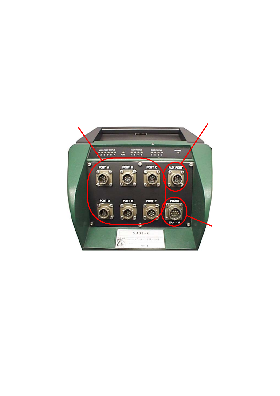
2.2 FRONT PANEL CONNECTORS
Input ports
A B C D E F
ux Port
Port A (B, C, D, E, F)
Input port from sensor digitiser.
Aux Port
Output port to PC (direct or via radio/telemetry link).
Power 12V input power supply to SAM.
NOTE
: See the appendix at the back of this manual for the pinouts of each plug.
ower
Issue D March 2001
6
Page 9
Operator’s Guide CMG SAM & CMG CRM
A
D
R
A
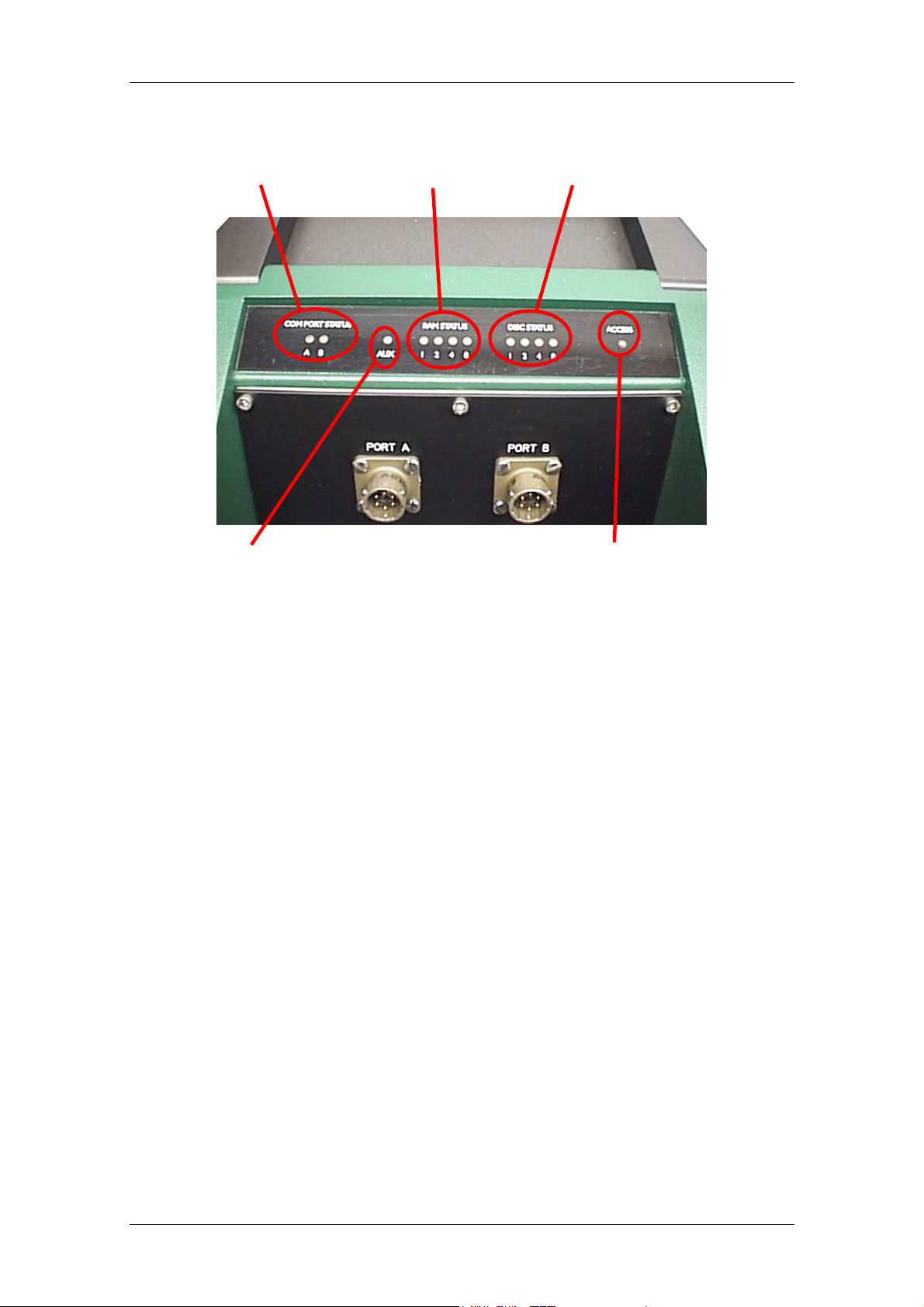
2.3 FRONT PANEL LED’s
Com Port Status
ux
AM Status
isc Status
ccess
Com Port Status
The data input stream LED’s show that the data is arriving to the port. During
the period of valid data the LED is continuously lit.
Aux
This ‘bi-colour’ LED will turn on green when the system receives the ‘ACK’
character from the block just transmitted (indicating that the data was received
correctly by the PC or SAM); or turn red if the system receives a ‘NACK’ (Not
ACKnowledged) from the last transmitted block.
This LED is turned off when the DM starts transmission of the next block of
data. Thus the time that this lamp is on green gives an indication of the amount
of free time available on the link.
RAM Status
A four element binary “bargraph” display is used to indicate the status of the
silicon file buffer. Green LED’s indicate the smallest binary bits (weight 1, 2,
&3) and red is used for the most significant bits (weight 8). For example, 2
green LED’s indicate
3
/16 full and 1 red LED indicates ½ full.
Disc Status
Another four element binary “bargraph” display to show the relative content of
the SCSI disc, similar to the RAM Status LED’s above. Data are transferred
from the silicon file buffer when it is 15/16th full (all LEDs lit) and data transfer
stops when it is 1/16th full (1st green LED).
Access
This lights red when the SCSI disc is being accessed, ie downloading data from
the silicon buffer.
Issue D March 2001
7
Page 10

Operator’s Guide CMG SAM & CMG CRM
2.4 CONFIGURATION
In order for the digital SAM to communicate both in and out, the baud rates of each port
must first be set to match the attached equipment. Initially the user will not know what
the baud rates for each port of the SAM are set at. It is essential therefore that in order
to communicate with the SAM the following procedure is adopted in the correct
sequence.
1) Plug the SAM into your PC serial port.
2) Start SCREAM. From the main start-up window (below), right click on File, and
select Setup
3) In the Setup window select the Com Ports tab (shown below) and right click on
Com1 (or which ever com port you are using on your PC).
Issue D March 2001
8
Page 11

Operator’s Guide CMG SAM & CMG CRM
4) From the next pop-up menu select Auto-Detect and a further pop-up window,
shown below, will appear.
EXPLANATION
The SAM at this moment is not powered. When it is plugged
in it will send out a ‘Status’ message. It is this we shall use to detect the output
baud rate.
5) Plug the power supply into the SAM and the window will change to that shown
below, indicating that it is reading data.
6) The baud rate detected between the SAM and your PC will appear here.
Click OK to return to the start-up window.
Issue D March 2001
9
Page 12

Operator’s Guide CMG SAM & CMG CRM
P
7) Depending upon whether the SAM is of the new flash memory type or not, there
are different options open from this point.
• If the SAM is the flash memory type there will be a 30 second delay
before this initial ‘boot-up’ when the SAM icon and ID will appear in the
start-up window as in 9) below
• If the Sam is an older model then proceed as in 8) below
8) The user can now establish a link between PC and SAM. Until the baud rate had
been set the SAM will not have received a full data packet and the main window
in SCREAM will still look blank as below. Recycle the power supply.
9) SCREAM will detect the SAM and display it as shown below
C Com port used
SAM ID
SAM icon
Issue D March 2001
10
Page 13

Operator’s Guide CMG SAM & CMG CRM
10) Now right click on the SAM icon or SAM ID (see picture above in 9)) and the
window shown below will pop up.
11) Select the Baud Rate tab and the following window will be displayed.
12) Right click on the current baud rate number in the display and a further popup
menu will display a list of baud rates available. Select the required baud rate
and it will appear in the Configuration Setup > Baud Rates window.
Issue D March 2001
11
Page 14

Operator’s Guide CMG SAM & CMG CRM
PORT CONNECTION CROSS REFERENCE TABLES
FUNCTION CONNECTOR
NAME
SAM
DIGITAL OUTPUT
SENSOR A
DIGITAL INPUT
SENSOR B
DIGITAL INPUT
SAM POWER
SUPPLY
AUX A PORT 0
PORT A B PORT 1
PORT B C PORT 2
POWER - -
SCREAM
CONFIGURATION
SETUP BAUD
RATES
TERMINAL
WINDOW SETUP
NOTE
Currently the Aux port that is displayed in the SCREAM window in 10)
above, is not available to the user. It is an internal facility only.
New Flash Memory SAM
FUNCTION CONNECTOR
NAME
SAM OUTPUT &
POWER SUPPLY
SENSOR A
INPUT
SENSOR B
INPUT
GPS
DATA OUT A PORT 0
DATA IN
PORT A
DATA IN
PORT B
GPS - -
SCREAM
CONFIGURATION
SETUP BAUD
RATES
B PORT 1
C PORT 2
TERMINAL
WINDOW SETUP
NOTE
When setting the baud rates, the user will need to consider the input rates
of the input channels compared to the output channel, and the
transmission rate of the of their data link from the SAM or CRM, that
they are compatible with each other and are able to sustain the rate of
transmission required.
13) When the user is satisfied that the selected baud rates are correct, click on the
System ID tab and change the Sam identification, if required, by clicking in the
relevant box, deleting and writing in a new ID. The System Identifier is
restricted to six alpha-numeric digits and the Serial Number is restricted to four
alpha-numeric digits.
14) Click on the Download button. The Configuration Setup window will
disappear as the SAM reboots and the new SAM ID will appear in the main
Start-up Window.
Issue D March 2001
12
Page 15

Operator’s Guide CMG SAM & CMG CRM
2.5 CHANGING S.C.S.I. DISCS
The 4 channel system takes approximately 25 minutes to fill the silicon buffer (8Mb)
and then about 10 minutes to transfer the data to disc. The disc should preferably be
changed during the period that it is not being accessed to avoid loss of data - if the disc
is switched off and removed during the backup time no data is lost as long as there is
still space available in the silicon file. When the disc is reinstalled backup will
recommence when the silicon file is once again 15/16ths full.
The disc status bargraph indicates disc usage in the same manner. For a 1 Gb disc each
1/16th segment is approximately 64 Mb. Ideally the disc should be replaced when all
LEDs are lit, indicating less than 64 Mb of space remaining. When the disc is
completely full no more data is written to disc and the silicon file buffer will start to
lose the oldest data. This situation is indicated by all 4 of the disc LEDs flashing
simultaneously.
Whenever the disc key lock is turned to remove the disc the system indicates this state
by alternately flashing the disc status LEDs (1+4 & 2+8). When the disc is reinstalled
and the key lock closed the system automatically powers up the disc, indicated by the
‘walking’ LEDs and the ‘access’ lamp illuminating, and checks the FAT for the disc
identity and space available.
If the disc-ID is different from the system-ID the FAT (File Allocation Table) will be
initialised and the disc treated as empty so the disc status will show empty (no LEDS).
If the disc-ID matches the system-ID the space used will be shown on the disc bargraph
and the system will continue to use this disc until full.
Thus to reuse a disc once the data has been retrieved the first location in the FAT should
be erased, or discs can be used in another SAM which would have a non-matching
disc/system-ID.
Issue D March 2001
13
Page 16

Operator’s Guide CMG SAM & CMG CRM
2.6 FLASH MEMORY UPGRADE
For the later models with Flash memory it is possible for the user to upgrade the SAM
or CRM software.
Guralp systems have a mailing list to keep Scream users up to date. To subscribe, send
an email to listserver@guralp.com with a single line in the body containing "subscribe
screamusers" (without the quotes). This will keep the users informed of latest upgrades
available.
To find out what the users current software version is, either double click on the SAM
icon in the main Start-up window and the Configuration Setup window will open up,
or right click on the icon and select Configure from the pop-up menu for the same
Configuration Setup window. The picture below shows “Software revision v.050”.
First obtain the latest software, then proceed as the following instructions.
1) In SCREAM’s main startup window, right click on the SAM icon and select
Terminal from the pop-up menu. This will open as shown
Issue D March 2001
14
Page 17

Operator’s Guide CMG SAM & CMG CRM
2) If the user presses the Enter key “ok” will appear on a new line, signifying that
there is two-way communication with the SAM.
3) Re-boot the SAM by turning the power off then on again and the initial boot-up
information will be displayed similar to that shown in the picture below.
4) In the instance shown above, the user then has 31 seconds to type “h8upload”
then press enter. After the next message “Ready to upload” appears, as shown
below, right click anywhere on the terminal window and select send file from
the pop-up menu.
Issue D March 2001
15
Page 18

Operator’s Guide CMG SAM & CMG CRM
5) Through your computers directories find the file to be uploaded and click on it,
or type in the full path and file name to display it in the File name edit box, then
click on the Open button.
Whilst the file is loading a countdown window as shown below will be on display.
6) Finally, re-boot the SAM by switching off and on, for the new program to
install.
Issue D March 2001
16
Page 19

Operator’s Guide CMG SAM & CMG CRM
3. DIGITAL I/O INTERFACE
The primary digital interface for the systems is the multiple serial port card. Each card
can contain 1 or 2 dual UARTs (Universal Asynchronous Receiver Transmitters) and
upto 2 cards can be fitted to a SAM/CRM unit. This allows a system with upto 8 serial
ports to be configured.
The multiple serial port card is usually configured as several data inputs for a SAM unit
allowing it to collect data from upto 8 digitiser units located locally, using RS232 or
RS422 links, or more remotely using radio links or telephone modems.
Each of the serial ports on a module can be configured for a wide range of standard
baud rates (with different settings available for transmit and receive channels), allowing
a wide range of data links to be used depending on the required data rates.
Each dual UART is optically isolated to avoid ground loops which could degrade the
performance of the ADC’s.
The serial port module includes 32k RAM for data buffering and formatting by the
transmission/reception process.
Issue D March 2001
17
Page 20

Operator’s Guide CMG SAM & CMG CRM
4. MICROPROCESSOR
The system is designed around a low power, high performance 16bit microprocessor
(Hitachi H8/500 series). This features a large address space (1Mb - 16 *64k pages) for
data storage and manipulation and many integrated functions such as multiple timers
and serial i/o ports.
The modular (paged) structure of the processor architecture is used to advantage in the
modular design of the system, each module being assigned to a separate ‘page’. Each
module is associated with an ‘I/O’ function and can be simply added to the system at an
available page. Every module includes 32k of RAM, which is used for data buffering
and workspace for the module’s software.
An important feature of the system design is its ability to synchronise the sampling of
the analogue to digital converter to an external time reference so that data samples are
accurately time stamped (at the source). The microprocessor timebase serves as the
system time reference and can be synchronised and tuned to an external reference such
as GPS to maintain sampling accurately synchronised to UTC. To avoid the cost and
power consumption of multiple GPS receivers in larger arrays the systems can also be
synchronised to a centrally transmitted time reference using a scheme similar to that
employed by the National Radio Time Standards (WWV,MSF and DCF77). As this
only involves sending 2 characters per second it can utilise a low bandwidth, even halfduplex link.
To achieve the high degree of timing precision required for a 24 bit digitiser system the
microprocessor timebase is run from a precision voltage controlled oscillator which is
software controlled from the external reference so that its frequency is accurately set
and maintained with temperature and ageing. The control is sufficiently accurate to
maintain precision sampling for long periods (several hours) in the absence of an
external reference once the system has stabilised.
All the timing functions are derived via the internal timer/counter channels from the
precisely set processor frequency so that sampling and time-stamping are accurately
maintained with reference to UTC. The system also automatically compensates for the
pure time delay introduced by the digital filtering/decimation of the DSP which
provides data output at different sample rates simultaneously.
The main microprocessor board incorporates a battery-backed Real-Time Clock and
RAM which is used to set the systems internal software clock at start-up independent of
the availability of the external time reference. The RAM is used to store system
parameters such as the optimum control voltage setting for the system timebase and the
system configuration.
The microprocessor module includes the (multi-tasking) system operating software in
EPROM on page ‘0’ with space for future expansion onto page 1 with additional ROM
and RAM. This module can also support either 128k or 512k of static RAM for system
workspace or data buffering depending on the system requirements (number of data
channels and sample rates).
The microprocessor serial port provides an interactive interface for system setup and
configuration.
Issue D March 2001
18
Page 21

Operator’s Guide CMG SAM & CMG CRM
5. DATA STORAGE
4.1 SILICON FILE
The solid state memory provides the SAM and CRM units with a large amount of lowpower storage and data buffering so that systems can utilise data transmission links on a
time shared basis or where the data link is unreliable providing local storage and retransmission. It is also used in conjunction with the hard disk storage option to buffer
data accesses to the disk allowing the disk to be powered down for extended periods to
reduce overall system power consumption.
The module can be configured with from 1 to 8 Mbytes equivalent to 1000 to 8000 data
blocks and upto 2 modules can be fitted to one system.
This unit uses low-power dynamic RAM (uPD42644 1Mb*4 Silicon file) accessed as
1k blocks in the processor address space. The processor provides the low frequency
‘self-refresh’ clock and control timing in conjunction with an FPGA to provide a rapid
access, large capacity circular data buffer without moving parts and the associated high
power consumption.
4.2 S.C.S.I. DISK
For systems that require long term storage of continuous and event triggered data, the
SAM unit features an interchangeable SCSI disk drive (>1 Gbyte). This allows the
acquired data to be retrieved simply by removing the disk drive and fitting a
replacement unit.
To minimise the system power consumption this module is usually used in conjunction
with a large RAM buffer (either system 512k static RAM or silicon file) so that the disk
drive can be powered down for long periods while data is accumulated in the buffer.
This intermediate buffering also allows the drive to be removed from the system for
data retrieval.
This module like all others occupies 1 page of the processor address space and includes
32k of RAM for read/write buffering in addition to the SCSI controller chip (53C94).
The disk filing system and data format have been designed especially for efficient
operation in a continuous real-time system. All data are stored in a 1k block with a
header which identifies the data stream (1 stream per ADC channel per sample rate) and
the time of the first sample (by definition on an integer UTC second). On the disk all
data blocks for a particular stream are linked together by disk address, the address on
each block pointing to the next block - the current end of data has a null pointer. Disk
space is allocated chronologically to the next ‘cluster’ (8 *1k blocks) of data available.
When the end of disk is reached the system can simply wrap round to the beginning of
the disk and automatically overwrites the oldest data. The data block format is described
in more detail in the next section.
Issue D March 2001
19
Page 22

Operator’s Guide CMG SAM & CMG CRM
SCSI FILE ALLOCATION TABLE
The system uses the first few blocks (1 block = 2* 512 byte sectors) of the SCSI disc to
store the pointers necessary to read and write the data streams. This table consistes of
16 byte fields used as 4 long word records.
The first field contains the ‘system-id’ (the first block header record - see next section)
used to identify the disc, followed by the address (sector number) of the first data on the
disc, the address of the end of data (next free sector) and the last address on the disc.
Subsequent fields are allocated to each data stream and start with the ‘channel-id’
(second field in the block header - see next section), the start address of the stream on
disc, the address of the last block of data for this stream and the final record is used for a
read access pointer.
Disc/System-id Start of data Start of free space End of disc
1st Stream id Start of stream End of stream Read pointer
2nd Stream id Start End Read
3rd Stream id Start End Read
etc ...
Issue D March 2001
20
Page 23

Operator’s Guide CMG SAM & CMG CRM
6. DATA TRANSMISSION PROTOCOL & DATA BLOCK STRUCTURE
The block structure of the SAM/DM data format (which does NOT use BDTS format)
lends itself to a simple block transmission/acknowledge protocol for transmission of the
data between multiple SAM/DM units and central data acquisition systems.
To send blocks of data from one system to another each block is packaged in a
‘transport’ layer, which consists of a short block header and a checksum tail. The header
consists of 4 bytes. The first is always an ASCII ‘G’ and the second is an incrementing
block number (modulo 256). The other 2 bytes contain the length of the data block
(binary, Motorola byte order). The checksum is also a ‘word’ (16 bit) being the sum of
all the bytes in the data block and the 4 header bytes.
To optimise the use of available transmitter bandwidth the transmitted data block is
truncated to the actual data length. As the systems currently only have 24 bit resolution
the redundant most significant byte in 32 bit data blocks is also not included in these
blocks i.e. 24 bit (3 byte) records are transmitted. This reduction is only applied to the
difference records - the first and last absolute values are still transmitted as 32 bit
values.
The transmission header consists of 4 bytes
Fixed identifier ASCII ‘G’ (hex 47)
Block sequence number 0 - 255
Block size in bytes (excludes Most significant byte
header and checksum) Least significant byte
The digitiser units transmit data as complete blocks become available without any flow
control except that provided by a simple positive/negative acknowledge (ack/nak).
Acknowledgement of received packets is not necessary as the transmitter only waits for
a nominal 100 mSec before moving onto the next block, if ready. To acknowledge
correct reception of a block the receiver should reply with an ‘ack’ character (here
defined as hex 01) and the least significant byte of the block’s ‘stream-id’. This allows
for a system which has a simple broadcast acknowledgement via a common link (radio
band) to many systems that are part of an array, each system is able to identify its own
ack/nak by matching the identifier byte. Reception of a positive acknowledgement will
enable the transmitter to terminate its wait timer and immediately proceed to the next
block.
When the receiver detects a transmission error it should reply with a ‘nak’ (here defined
as hex 02) and the identifier byte. This will cause the transmitter to re-send the block of
data.
Issue D March 2001
21
Page 24

Operator’s Guide CMG SAM & CMG CRM
DATA BLOCK STRUCTURE
Block Header
All elements of the GCF data block can be considered as long words (4 bytes or 32
bits).
The GCF block header consists of 4 elements (16 bytes) as shown
System-ID 32 bit number (base 36) - see below
Stream-ID 32 bit number (base 36) - see below
Date/Time 15 bit Day number 17 bit Second number
Format R.F.U. s/sec compression block size
The first element contains the unique identifier for the system from which the data
came. This is usually a six character string encoded in base 36 i.e. each character can be
extracted by taking the number modulo 36 and converting to the characters 0 - 9 and A Z. Only positive integers are allowed (most significant bit=0) limiting the range of
values to 0 - 7FFF,FFFF in hex (2,147,483,654 decimal) or ZIK0ZJ in base 36. This
field can be set to any convenient unique identification number by the user, but units are
shipped from the factory with this set to the factory Works Order number e.g. WO1234.
The second element identifies the stream of data i.e. source as horizontal or vertical
sensor and its origin from the digitiser. This again uses base 36 encoding, but this field
should not be changed as it is dynamically set according to the configuration of the
digitiser.
This is best viewed in its base 36 form i.e. as 6 alphanumerics. The 4 most significant
characters are the instrument serial number (decimal) and the 2 least significant
characters encode the sensor component and digitiser output.
Stream-ID digit 4 digit 3 digit 2 digit 1 Z,N or E see text
serial number comp source
The Guralp DM24 digitisers can output upto 4 data rates per component simultaneously.
The third header element contains the date/time information as a 15 bit day number
packed with a 17 bit second number. The second number is the time since midnight maximum 86,399 normally but possibly 86,400 in the case of a ‘leap second’. The day
number increments on the roll-over of the seconds count at midnight. The origin of the
day number (day zero) was 17th November 1989. Thus the date/time can be uniquely
decoded for the next 80 years.
The final header element defines the format of the data in the block, i.e. compression,
sample rate, size etc.
The most significant (first) byte is currently unused and is set to zero.
Issue D March 2001
22
Page 25

Operator’s Guide CMG SAM & CMG CRM
The next byte contains the sample rate (s/sec in binary). If this field is zero this indicates
that the block contains status (text) information.
The third byte is used to specify the compression format for all the data in the block.
The 3 least significant bits are used to indicate whether the data elements (32 bits)
contain 1, 2 or 4 sample points - i.e. a value 4 indicates that the data records should be
treated as 4 8 bit differences, a value 2 means the data are 2 16 bit differences and the
value 1 the data are a single 32 bit difference.
The fourth byte contains the count of the number of data records (32 bits).
The product of these last 2 bytes can be used to calculate the total number of sample
points in the block.
Block Data.
First absolute value 32 bits
First 1, 2 or 4 differences 1*32bit, 2*16bit or 4*8bit values
....
....
Final 1, 2 or 4 differences same format 1, 2 or 4 differences
Final absolute value 32 bits
The first data record in the block, following this format record, is the initial 32 bit
absolute value (forward integration constant). The last record is the final 32 bit absolute
value (reverse integration constant). Between these are the specified number of data
records. Each data record contains the specified number of 8, 16 or 32 bit differences
from the previous value. The first difference is always zero as it corresponds to the first
sample.
By definition each data block starts on an integral second and contains an integral
number of seconds of data. The data block has a maximum size of 1024 bytes (16 byte
header + 8 bytes for start and end value leaves 1000 bytes for data differences e.g. at 8
bit compression the block will contain 1000 sample points i.e. 10 seconds of data at 100
s/s - using minimum compression (32 bit) only 2 complete seconds of data can be fitted
in a block at this sample rate - 2*100*4 = 800 bytes). Changes in signal level will result
in the compression algorithm having to change the format so blocks are not necessarily
filled to the maximum specified capacity, when the next second of data requires more
dynamic range.
The data has this format when processed and stored in the DM and SAM units
(maintaining data values on word boundaries in the processor), but when data blocks are
transmitted via the serial ports, blocks of 32 bit differences have the redundant most
significant byte (of the difference values) omitted to optimise the efficiency of the serial
transmission.
Issue D March 2001
23
Page 26

Operator’s Guide CMG SAM & CMG CRM
7. SAM User Commands
Commands are NOT case sensitive.
Not all versions of SAM support all the features listed in this table.
Command Description Reboot*
HELP Displays firmware version number, release date and
command list
SET-ID Interactive command. Follow prompts to set System and
Stream IDs.
SET-CLOCK Interactive command to set the time in the SAM unit.
This time is only used for time-stamping of SAMgenerated status messages.
p n BAUD Sets port 'p' to baud rate 'n' for Tx and Rx. For 115200
baud, use n=1152.
p = 0 for ‘Data-Out’ or ‘Aux’ connector on front panel
p = 1 for Port A
p = 2 for Port B
etc.
p n RX-BAUD Sets the Rx baud rate independently of the Tx baud rate.
Should only be used when connecting to devices that
support asymmetric baud rates on a serial port.
p n TX-BAUD Sets the Tx baud rate independently of the Rx baud rate.
Should only be used when connecting to devices that
support asymmetric baud rates on a serial port.
p SYNC-ON Enables transmission of stream-sync signal on port ‘p’.
See ‘BAUD’ command for port mapping. p >= 1
p SYNC-OFF Disables transmission of stream-sync signal on port ‘p’.
See ‘BAUD’ command for port mapping. p >= 1
p DUPLEX Sets port ‘p’ for normal duplex operation p >= 1 Y
p SIMPLEX Switches off transmission on port ‘p’ if a BROADCAST
port is specified (output is re-directed to BROADCAST
port). p >= 1
p BROADCAST Selects port ‘p’ for all transmissions (used in
conjunction with SIMPLEX command). Set p=0 to
disable broadcast mode.
n GPS-TYPE
Sets type of synchronisation source to be used.
n = 0 no time signal
n = 2 Garmin
n = 3 stream-sync
Not all versions support all combinations
n HR-CYCLE Specifies period in hours between power-on of GPS.
n=0 disables power-cycling of GPS (runs continuously).
When n>0, GPS will automatically be switched off
when clock synchronization is within a small tolerance.
RE-BOOT The command prompts the operator to confirm this
operation with ‘y’. The system will then automatically
reset after a delay of about 2 s.
SET-RTC Sets the Real Time Clock. Only used for Status
timestamping.
N
Y
Y
Y
Y
Y
Y
Y
Y
Y
Y
N
-
Y
Issue D March 2001
24
Page 27

Operator’s Guide CMG SAM & CMG CRM
Use only if SET-CLOCK command is not recognised.
Usage:
HEX yyyy mm dd hh mm ss 0 SET-RTC
n MB-FILE Sets the amount of silicon file to use for transfers to the
Y
disk, 'n' in Megabytes
RECYCLE Sets the disk mode to overwrite the oldest data (circular
N
store)
USE-ONCE Sets the disk mode to non-circular mode (stops
N
recording when the disk is full)
RESET-DISK or
RESET-DISC
DIR Lists the contents of the disk, including start and end
Resets the SCSI and marks as blank. The contents will
be wiped from the disk on next write.
N
N
dates and times.
FLUSH Forces the contents of the Silicon File to be transferred
N
to disk. Useful to clear out memory prior to disk
removal or unit power-down
OPEN i s Open a pass-thru link to the instrument with System ID
N
'i' and serial number 's'.
STREAMS? Lists all streams detected by the SAM, displaying the
N
serial number (and tap information), System ID, and
port the stream is received on. Normally used in
conjunction with OPEN command.
GO or
CLOSE
Leave command mode and resume transmission of data
blocks
N
* Some commands require a re-boot of the SAM in order for the changes to take effect.
Note that if several settings are changed, it is not necessary to re-boot after each change
– only one re-boot is necessary after all required changes have been made.
Issue D March 2001
25
Page 28

Operator’s Guide CMG SAM & CMG CRM
8. CONNECTOR PINOUTS
INPUT PORTS
(A & B on SAM 2)
(A, B, C, & D on SAM 4)
(A, B, C, D, E, & F on SAM 6)
FUNCTION
Data Tx A
Data Rx B
Ground F
FUNCTION
Terminal Tx (Transmit to terminal) A
Terminal Rx (Receive from terminal) B
Data Rx C
Data Tx D
Ground F
FUNCTION
0 V A
+12 V dc B
CONNECTOR
KPT 06F-10-6S
AUX PORT
(OUTPUT)
CONNECTOR
KPT 06F-10-6S
POWER
CONNECTOR
KPT 06F-12-10S
Issue D March 2001
26
Page 29

Operator’s Guide CMG SAM & CMG CRM
FLASH MEMORY S.A.M
CONNECTOR PINOUTS
DATA IN
(Ports A & B on SAM 2)
FUNCTION
Data Tx A
Data Rx B
CTS out C
0 Vout E
Signal Ground F
RTS out, or, +V out
(manufactured option)
FUNCTION
0 Vin A
+ Vin B
CTS Out C
RTS Out D
Signal Ground G
Data Rx J
Data Tx K
0V Supply to GPS A
+V Supply to GPS from SAM B
1Hz Reference, RS232 Level Isolated C
Terminal Tx (Transmit to terminal) E
Terminal Rx (Receive from terminal) F
Isolated GROUND G
GROUND H
COM2 Tx (Transmit to GPS) J
COM2 Rx (Receive from GPS) K
CONNECTOR
KPT 06F-10-6S
DATA OUT
CONNECTOR
KPT 06F-10-6S
GPS PORT
FUNCTION
CONNECTOR
D
02E-12-10P
Issue D March 2001
27
 Loading...