

Page 1

CMG-DM24S12AMS
Acquisition and Monitoring System
Operator’s guide
Part MAN-D24-0002
Designed and manufactured by
Güralp Systems Limited
3 Midas House, Calleva Park
Aldermaston RG7 8EA
England
Proprietary Notice: The information in this manual is
proprietary to Güralp Systems Limited and may not be
copied or distributed outside the approved recipient's
organisation without the approval of Güralp Systems
Limited. Güralp Systems Limited shall not be liable for
technical or editorial errors or omissions made herein,
nor for incidental or consequential damages resulting
from the furnishing, performance, or usage of this
material.
Issue Date Comments
A 2003-01-26 First issue
B 2004-03-19 Rewrite
Page 2

CMG-DM24S12AMS Operator's guide
Contents
Contents..................................................................................................................2
1 Introduction........................................................................................................ 3
2 Quick start........................................................................................................... 9
3 Using Scream!................................................................................................... 13
System ID.................................................................................................... 15
Output control............................................................................................16
Triggering................................................................................................... 20
Mux Channels............................................................................................ 29
Ports............................................................................................................. 30
System..........................................................................................................32
Triggering................................................................................................... 33
Calibration.................................................................................................. 34
Data Flow.................................................................................................... 35
Recording.................................................................................................... 36
Files.............................................................................................................. 38
The UFF file format....................................................................................40
My Client.....................................................................................................43
My Server....................................................................................................44
4 Inside the DM24S12AMS................................................................................ 52
Power...........................................................................................................53
GPS...............................................................................................................53
USB to RS232 converter............................................................................ 54
5 Using CMG-5U sensors................................................................................... 58
Unpacking and packing............................................................................60
Initial testing...............................................................................................60
Installing the sensor...................................................................................61
Centring the 5U..........................................................................................63
Electrical connections................................................................................ 64
Absolute calibration...................................................................................65
Relative calibration.................................................................................... 65
Using a DM24 series digitiser for calibration.........................................67
Appendix A: Connectors and cables................................................................ 71
Data ports....................................................................................................71
Power ports.................................................................................................73
PC ports.......................................................................................................74
Appendix B: Specifications................................................................................ 78
2 Issue B
Page 3
CMG-DM24S12AMS Operator's guide
1 Introduction
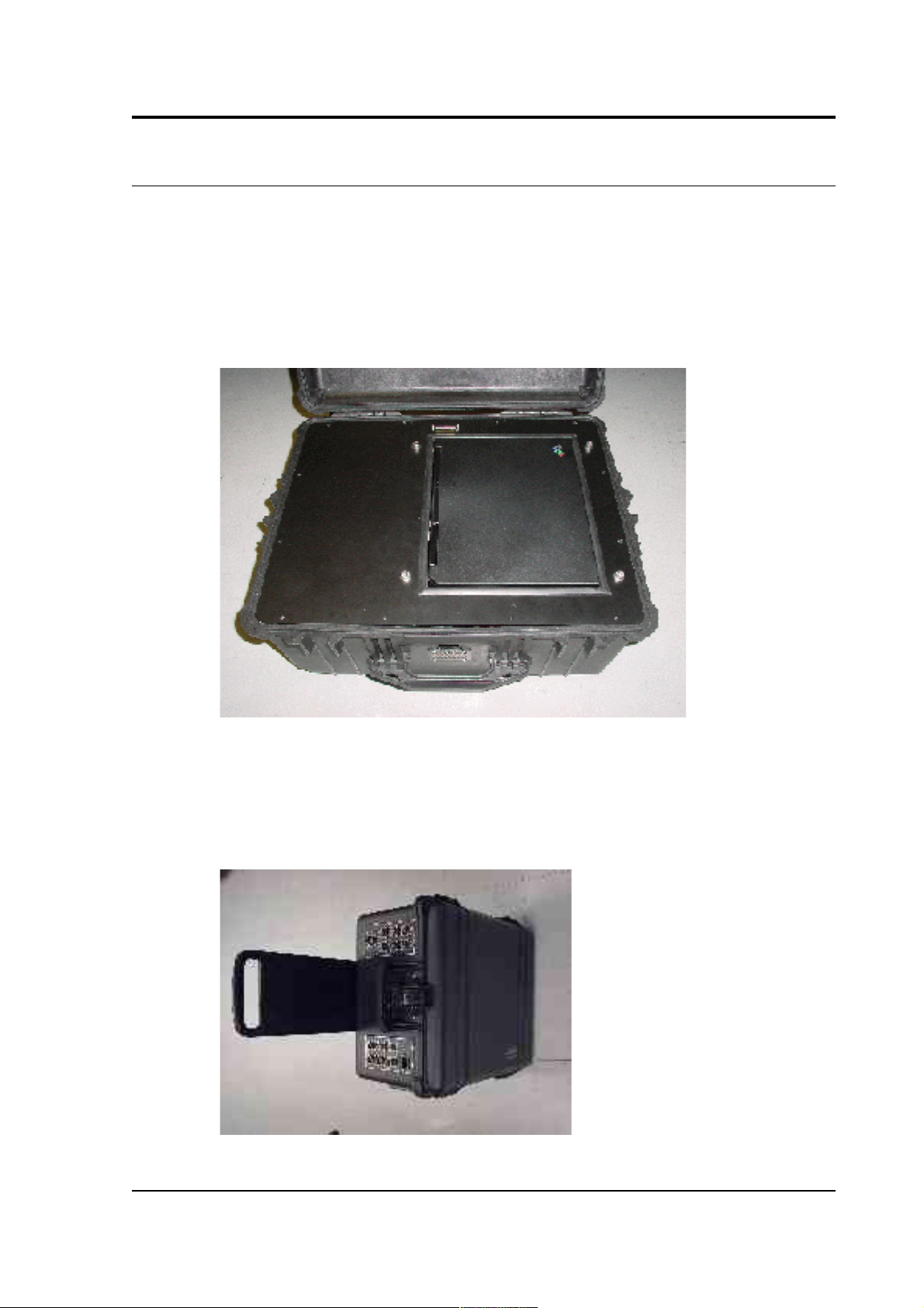
The Güralp CMG-DM24S12AMS 12-channel acquisition and monitoring
system is a self-contained seismic data collection station specially
configured to operate 12 single-component CMG-5U strong motion
accelerometers. It combines all the features of the CMG-DM24 3 or 6channel digitiser with an integrated laptop PC for viewing and
transmitting the recorded data.
The housing of the digitiser is made from high impact copolymer
polypropylene with mil-spec connectors fitted on to metal plates. There
is also a small internal pocket for storing cables or documentation. The
unit features a roller trolley design for ease of transportation.
March 2004 3
Page 4
CMG-DM24S12AMS Operator's guide
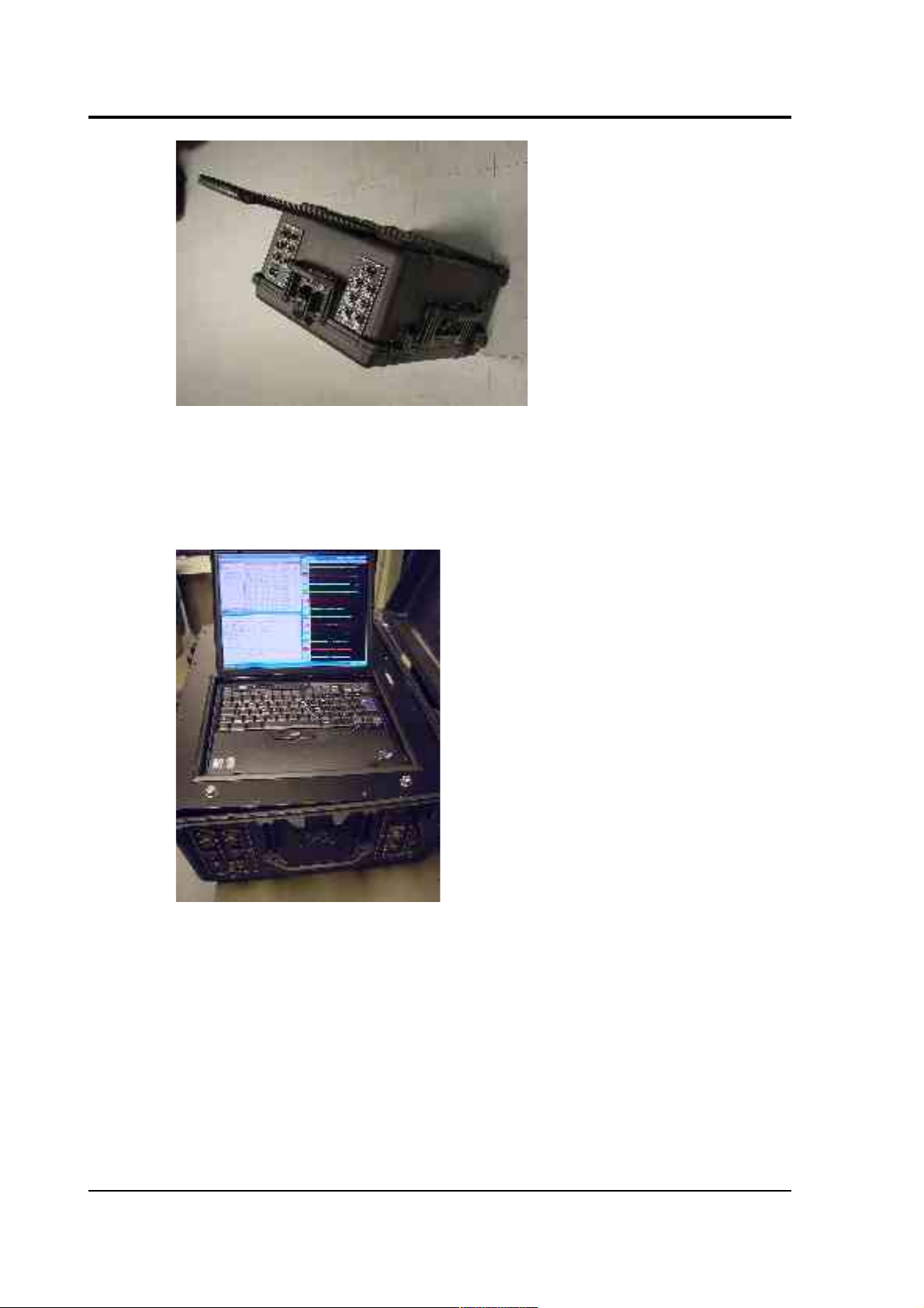
The integrated laptop PC is supplied with Güralp Systems’ Scream!
software pre-installed. Using the PC, you can process incoming data and
transfer it to any compatible storage device over a telephone line
(modem) or network connection.
Care must be taken when handling the integrated PC, which is a
standard laptop model. In particular, you should not force the screen lid
closed. Closing the lid would cause the PC to enter hibernation mode,
and halt all data collection. Instead, you should rest the lid on the rubber
stops fitted to the PC's keyboard, so that the PC remains active and the
digitiser functions as expected. There is sufficient room within the
DM24S12AMS unit to allow you to leave the PC in this state and still
close the outer case completely.
4 Issue B
Page 5
CMG-DM24S12AMS Operator's guide
Note: Because the integrated PC requires ventilation, the DM24S12AMS
is not completely waterproof. The water level must not be allowed to
reach the ventilation grilles on the sides, front and rear of the box at any
time.
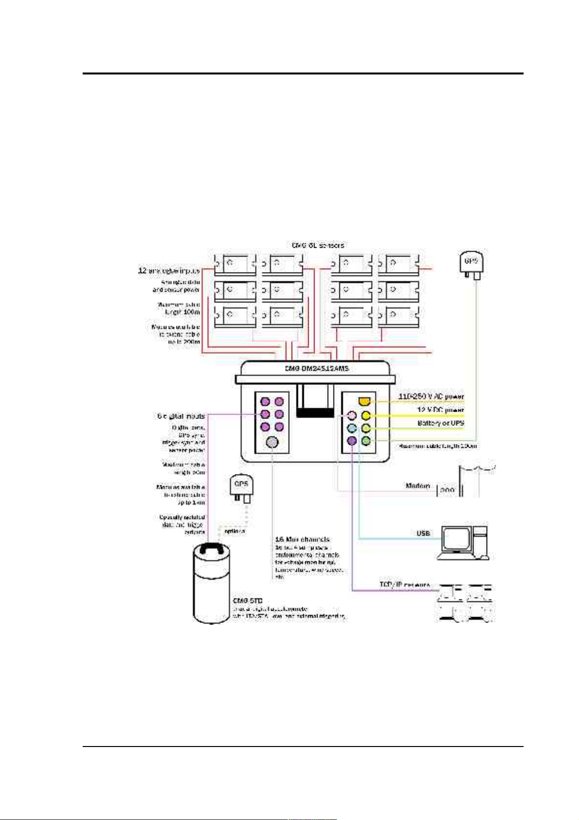
A typical setup for a DM24S12AMS acquisition and monitoring system
is shown below.
March 2004 5
Page 6
CMG-DM24S12AMS Operator's guide
Here, the twelve CMG-5U uniaxial sensors can be distributed
throughout a building to capture its response to ground motion, while a
digital CMG-5TD unit is embedded in the ground nearby to capture the
ground motion itself. Data from all thirteen instruments is fed into the
DM24S12AMS, where it can be stored and processed on-site or
alternatively sent across a local network or the Internet. If required, up
to five further digital instruments can be connected to the
DM24S12AMS (not shown).
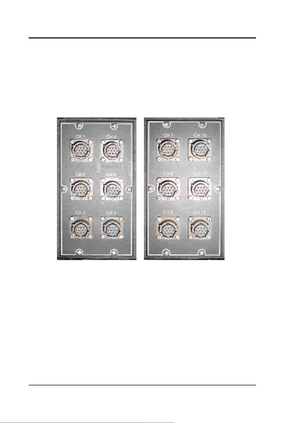
The DM24S12AMS unit’s 12 analogue input connections are each
identical to the output connection of the Güralp CMG-5U. These
connections also serve as the sensors’ 12V power supply. If required,
other types of sensor may also be wired to a DM24S12AMS module.
Using compatible connections, you can control all the sensors through
the module, either using its integrated PC or from a remote location on
your network. The digitiser can also provide common calibration and
GPS timing signals to all the sensors.
All DM24 digitiser units are fitted with high-impedance, low-noise,
differential input pre-amplifier modules.
6 Issue B
Page 7
CMG-DM24S12AMS Operator's guide
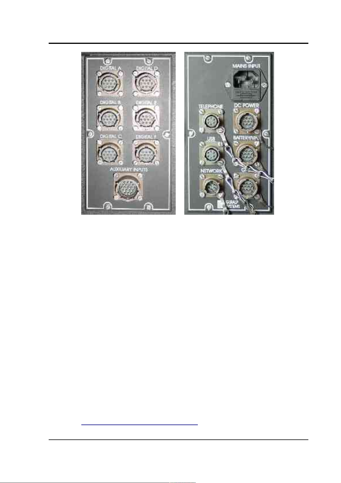
In addition to the main 24-bit analogue inputs, the digitiser module
features an additional 16 slow rate 16-bit resolution analogue inputs.
The inputs to the slow rate channels are through the connector marked
AUXILIARY INPUTS. These inputs are all single-ended and use a fixed
sample rate of 4 samples/s.
The DIGITAL A − F connectors are provided for use with Güralp
Systems digital output seismometers (such as the CMG-3TD) or
accelerometers (CMG-5TD). Like the analogue inputs, the DIGITAL A −
F connectors can supply power to the digital sensors. Alternatively, if
required, the DIGITAL A − F can be used as serial interfaces (e.g. to
remote installations connected by modem.)
The DM24S12AMS unit can be powered either from 110 – 250V AC
mains power, or from a 12 V DC power source. In addition, a
BATTERY/UPS connector is provided, for attaching to a rechargeable
battery or UPS. If power is provided through one of the other sockets,
the battery will be recharged at 14 V. There is also an external USB port,
and a standard parallel port within the casing.
For more details on the internal design of the DM24S12AMS, see
Chapter 4, “Inside the DM24S12AMS”.
March 2004 7
Page 8

CMG-DM24S12AMS Operator's guide
1.1 Feature overview
• A built-in Digital Signal Processor (Motorola 56002) provides
simultaneous multiple sample rate data streams at user selectable
rates. Up to 4 streams of data for each component are available at
sample rates from 1 to 200 samples/s.
• A precision microprocessor-controlled time base synchronizes
Analogue to Digital Converters, and DSP and time-stamps data
blocks.
• Time synchronization to external GPS or serial time code.
• A control microprocessor (Hitachi H8) formats and buffers data
in an on-board 512k RAM ring buffer.
• Efficient data storage and transmission using the Güralp
Compressed Format.
• Serial data output (RS232) at user selectable baud rates—options
of RS422, DPSK or fibre-optic.
• Built-in microprocessor system configuration and sensor control,
including locking and unlocking, centring and calibration.
• Low system power consumption, less than 3W (excluding the
integrated PC)
• Flash EEPROM for program code and filter coefficients.
8 Issue B
Page 9
CMG-DM24S12AMS Operator's guide
2 Quick start
1. If you are using a GPS timing signal to synchronize your
instruments, first connect a GPS receiver to the digitiser's GPS
socket.
2. Power up the system. The DM24S12AMS module can take power
from the mains, or from any ~12 V DC supply such as a battery or
UPS. If a rechargeable battery is connected to the BATTERY/UPS
socket, and enough external power is provided, the battery will
be recharged as required.
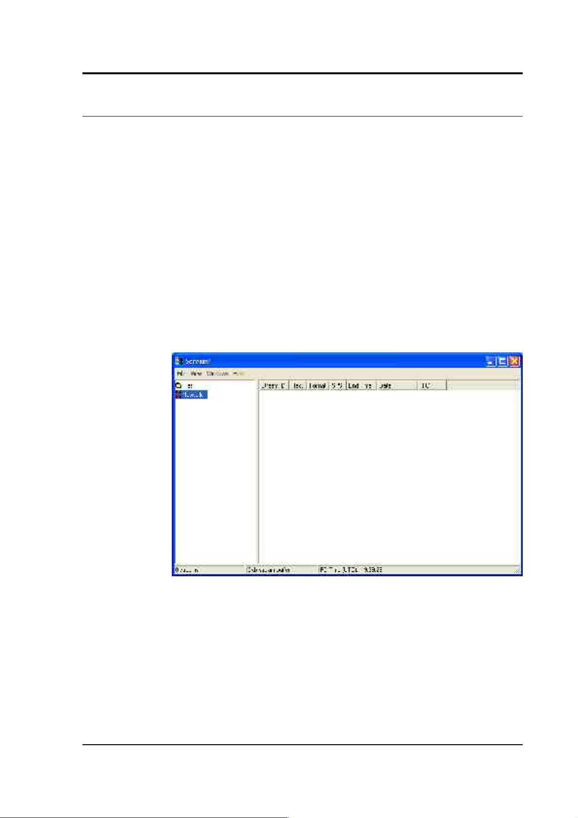
3. Open the lid of the unit, and power up the built-in laptop PC,
which is configured to automatically run the latest version of
Güralp's Scream! software. After a short while, Scream!'s main
window will open:
4. Scream! will then connect to the digitiser. The DM24S12AMS
houses two separate 6-channel digitiser modules, which work on
CH 1-6 and CH 7-12 respectively. After a short wait, the two
modules should appear under Local in the left hand pane, each
on its own Com port.
March 2004 9
Page 10

CMG-DM24S12AMS Operator's guide
5. Whilst Local is selected in the left-hand pane, the list on the right
details all the data streams coming from any instrument directly
attached to the DM24S12AMS. Clicking on Network will display
all data coming from networked instruments or other Scream!
servers, if there are any. Clicking on the entry for a particular
digitiser picks out streams coming from that digitiser; likewise,
clicking on a Comxx entry will display only streams attached to a
particular Com port.
6. The columns in the table provide useful information about each
stream.
Stream ID: A unique name for the data stream, being a
combination of six letters A – Z and numbers 0 – 9. Streams
ending in “00” carry status information about the internal
digitiser, whilst other streams contain data coming from
connected instruments. The slow-rate environmental channels
(Mux channels) generally have Stream IDs ending in “Mx” where
x is a hexadecimal digit (0 – 9 or A – F), whilst other Stream IDs
are used for seismic data from attached instruments.
Rec.: Whether the data stream is currently being recorded to the
hard disk.
Format: The format of the data the stream is producing; one of 8,
16 or 32 bit.
SPS: The sampling rate of the data stream, in samples per second.
Status streams ending in “00” do not constantly output data and
have an SPS of 0. By default, the stream list is sorted in order of
sample rate, with the status streams at the bottom.
End time: The time the data stream last sent data to Scream!. The
time is taken from the digitiser's internal clock, which can be set
from signals coming from an attached GPS receiver (see “GPS” in
Section 4.1).
Date: The date the data stream last sent data to Scream!.
10 Issue B
Page 11
CMG-DM24S12AMS Operator's guide
RIC: The ‘Reverse Integrating Constant’. In effect this is the value
of the last sample received. This is most useful for reading mass
positions or other environmental streams.
7. You can now connect a Güralp CMG-5U sensor to one of the CH
1 – 12 connectors on the side of the unit. See Section 5.2,
“Installing CMG-5U sensors” for more details.
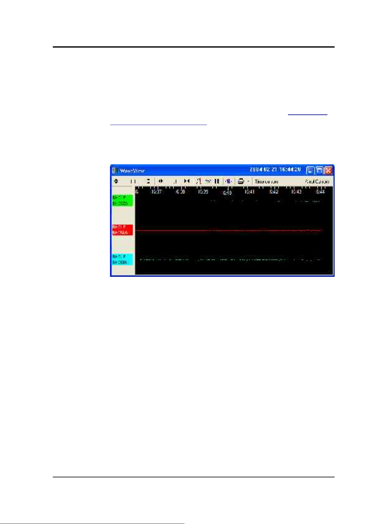
8. Double-click on one of the streams to open a WaveView window
for viewing the data.
9. You can add further streams to the WaveView window by
selecting them from the streams list and dragging the selection
into the WaveView window.
10.You can open new WaveView windows by making a selection of
streams from the list and double-clicking on that selection.
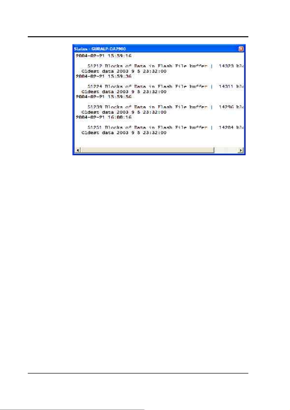
11.To see the status information coming from each digitiser, rightclick on the status stream (ending in “00”), and select View from
the pop-up menu. A Status window will open containing all the
text that has been received since power-up.
March 2004 11
Page 12
CMG-DM24S12AMS Operator's guide
The first blocks will give the boot message from the digitiser,
including its software revision and the data streams selected for
downloading and triggering. Later blocks give information on
visible GPS satellites, the location of the GPS antenna and time
synchronization status. Also displayed are the baud rates
currently used for each channel and for the data link.
The following chapters describe a selection of the features available in
the Scream! 4 software provided with the DM24S12AMS. For full
information on what you can do with Scream! please consult its own
user guide or the extensive online help.
12 Issue B
Page 13

CMG-DM24S12AMS Operator's guide
3 Using Scream!
3.1 Configuring digitisers
The DM24S12AMS unit contains two built-in 6-channel DM24 digitiser
modules, one running the ports CH 1 – 6, and the other using ports CH
7 – 12. These may be configured from within Scream!, together with any
external Güralp digital instruments attached to the DM24S12AMS's
DIGITAL A – F connectors.
Scream! 4 distinguishes between configuration and control of digitisers.
The most important difference is that a digitiser may be controlled
through Scream! whilst in the process of acquiring data, whereas
configuring a digitiser requires that it be rebooted (with consequent loss
of data.)
To change the configuration of any attached digitiser, including the two
6-channel digitisers installed within the DM24S12AMS unit, right-click
on the digitiser's entry in the list to the left of Scream!'s main window
(not the Local or Comxx icons) and click Configure.... Scream! will then
contact the digitiser and retrieve its current configuration, a process
which will take a few seconds, after which the Configuration setup
window will be displayed. Once you are happy with any changes you
have made in the Configuration Setup window, click UPLOAD to send
them to the digitiser and reboot. This will take a short while.
To control a digitiser whilst it is running, either right-click on the
digitiser's entry in the list and click Control..., or double-click the entry.
In either case Scream! will contact the digitiser to retrieve control
information and display the Control window. The options you can
control immediately are:
• The type of sensor you are using
• GPS power cycling options
• The short-term and long-term average values for triggering (but
not which streams perform the trigger, or which are output by it)
(see also “Triggering” in Section 3.1)
March 2004 13
Page 14

CMG-DM24S12AMS Operator's guide
• The length of pre-trigger and post-trigger periods (see also
“Triggering” in Section 3.1)
• Calibration signal options
• Mass control functions
Some of these options can also be altered in the Configuration setup
window. For more information on the Control window, see Section 3.2,
“Controlling digitisers”.
If you need a more powerful interface to the digitiser modules, you can
also issue commands to it directly using Scream!'s terminal mode. A
terminal window is opened by right-clicking on the digitiser's entry in
the list and selecting Terminal.... The digitiser will stop collecting data
while you have a terminal window open. For more details on the
DM24's terminal mode commands, please see its technical
documentation (available from Güralp Systems.)
The remaining sections of this chapter describe in detail the
configuration options available for the DM24S12AMS's in-built
digitisers. Many of these options will also be available for other Güralp
digitisers or digital sensors connected to the unit's DIGITAL A – F ports.
For the most accurate information, you should consult the Operator's
Guide for the digitiser or sensor you connect.
14 Issue B
Page 15
CMG-DM24S12AMS Operator's guide
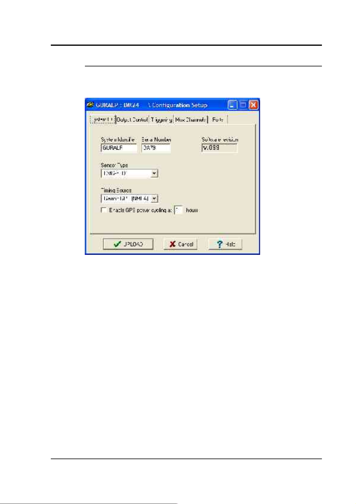
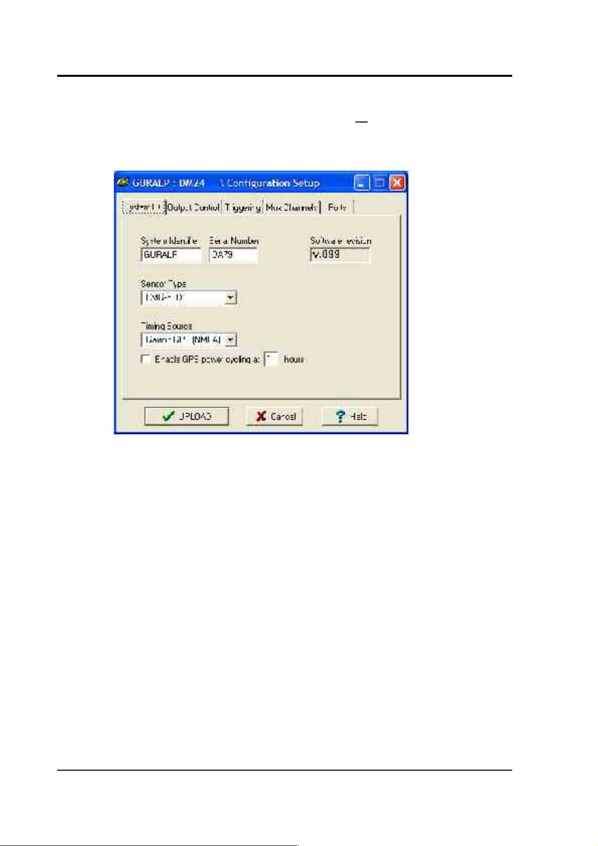
System ID
The System ID pane gives information about the digitiser and its internal
software, and allows you to change GPS timing parameters.
System Identifier and Serial Number: The digitiser type is identified by
its system identifier and serial number. Every data and status block
generated by the digitiser includes these two fields at the beginning, so
that the block’s origin can be identified. On delivery from the factory,
the system identifier and the serial number are set to the GSL works
order number and the digitiser’s serial number, but you can set either
value to any combination of up to 6 letters A-Z and numbers, such as an
abbreviation of your institution’s name, etc.
Sensor Type: If the sensor attached to the digitiser is a Güralp velocity
sensor, useful seismometer functions (such as sensor locking, centring,
and calibration) may be controlled through the digitiser. The type of
sensor programmed with this option determines which functions will be
available through the Scream! digitiser configuration set-up interface or
through interactive commands. The in-built digitisers are already
programmed to the proper sensor type for Güralp CMG-5U uniaxial
sensors.
March 2004 15
Page 16
CMG-DM24S12AMS Operator's guide
GPS Type: The digitiser needs to be able to time-stamp accurately all
data that passes through it. It can set its clock either by receiving time
signals from the GPS satellite network using an attached Garmin GPS
unit, or by taking time information from a central site (stream sync
mode). In stream sync mode, the digitiser expects to receive GCF packets
from the central timing source (which may have its own GPS unit, or
take signals from one of the radio time standards).
Enable GPS power cycling: If you are using a GPS unit to receive time
signals, but do not experience significant drift in the system's clock (for
example, in a stable-temperature environment), you can save power by
selecting Enable GPS power cycling. With this option in use, the GPS
time is only checked at intervals of a specified number of hours.
Disabling this option keeps the GPS unit running constantly; if you have
ample power, this will give the most accurate results. You can choose
any whole number of hours for the interval.
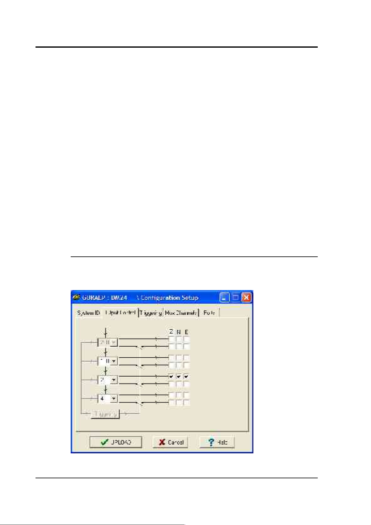
Output control
The Output control tab allows you to configure which data streams are
sent to Scream! from each digitiser.
16 Issue B
Page 17

CMG-DM24S12AMS Operator's guide
Güralp instruments output data sampled at 2000 Hz, which is then
filtered and reduced to a lower rate (decimated) using an on-board digital
signal processing unit, or DSP. The DSP has four filtering-decimation
stages, which run one after the other. The output of each stage is called a
tap. The first filter stage, tap 0, is pre-set to reduce the data by a factor of
10 to 200 samples/second.
Each of the three remaining taps may be configured for a different
decimation factor by choosing values from the drop-down menus on the
left. Decimation factors of 2, 4, 5, 8, and 10 are available. The numbers
visible in the drop-down menu of each tap are the data rates that each of
the possible decimation factors will provide, given the settings of the
taps above it. Only integer (Hz) data rates are allowed: thus, for
example, if one tap emits data at 25 Hz, the only possible further
decimation factor is 5.
To the right of each decimation factor menu is a grid of check-boxes.
These boxes mark which streams of data to record at each sample rate.
The screenshot above shows a possible configuration for a triaxial
instrument (similar to a CMG-5TD connected to one of the ports
DIGITAL A – F).
If you want to change the names used for the channels, click in the white
box containing a Z in the above picture, and type a letter or number. It
will name the channels with a sequence of letters or numbers beginning
with the one you choose (e.g. A, B, C; 2, 3, 4; 9, A, B), unless you type Z
in which case they will revert to Z, N, and E.
Each combination of channel and tap has two check-boxes. The upper
check-box of each pair activates continuous output, whilst the lower
activates triggered output. In the example above, the digitiser will output
data continuously for all three channels at Tap 2, but never for any other
taps. If you do not need all the streams to output at all rates, you should
leave boxes unchecked to save communications capacity. You cannot
check both continuous and triggered output for the same channel and
tap.
March 2004 17
Page 18
CMG-DM24S12AMS Operator's guide
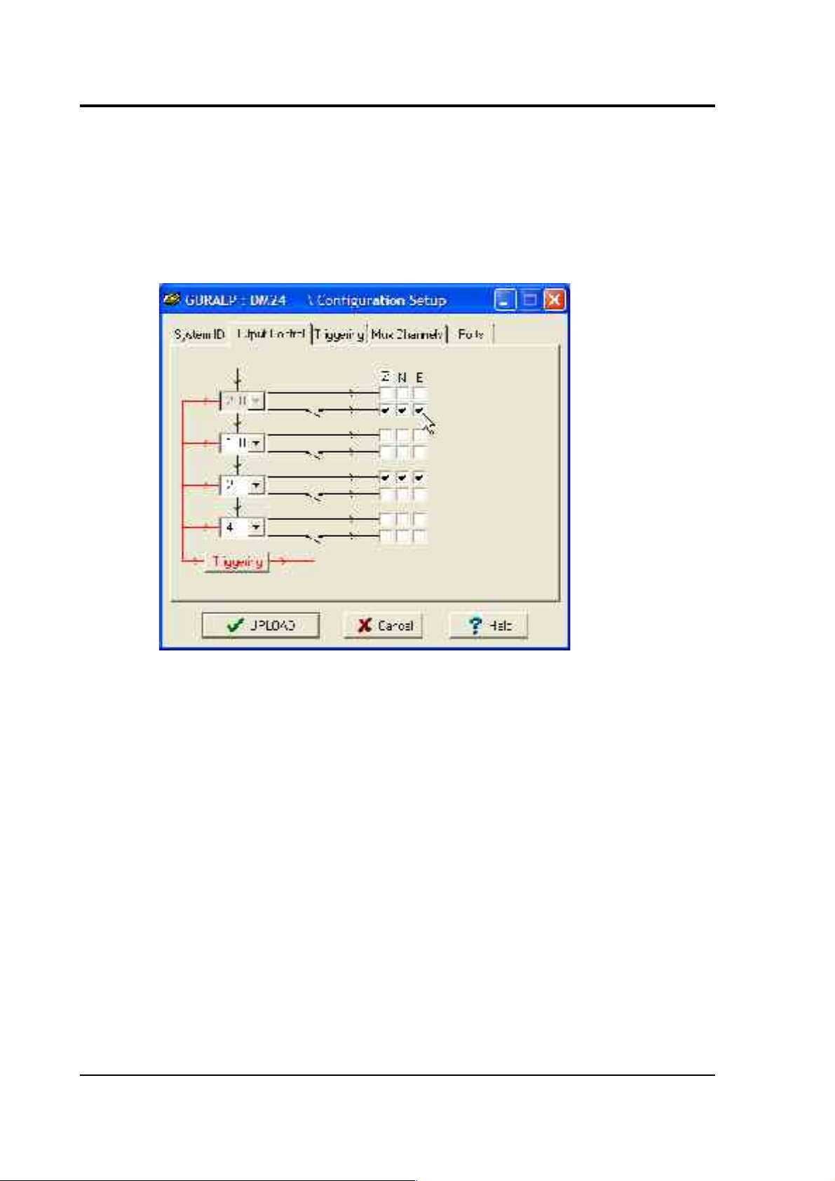
Triggered output causes the digitiser to output data only when a
particular set of trigger criteria are met. This is shown diagrammatically
as data passing through a switch. In the example above, we might want
the more detailed data from Tap 0 to be recorded only when an event
registers at some other tap. To do this, the lower check-boxes of Tap 0
should be ticked:
With this configuration uploaded, Tap 2 will continue to produce output
at all times, but Tap 0 will also emit data whenever the trigger criteria
are met. The Triggering button is now shown in red to remind you that
the trigger is active.
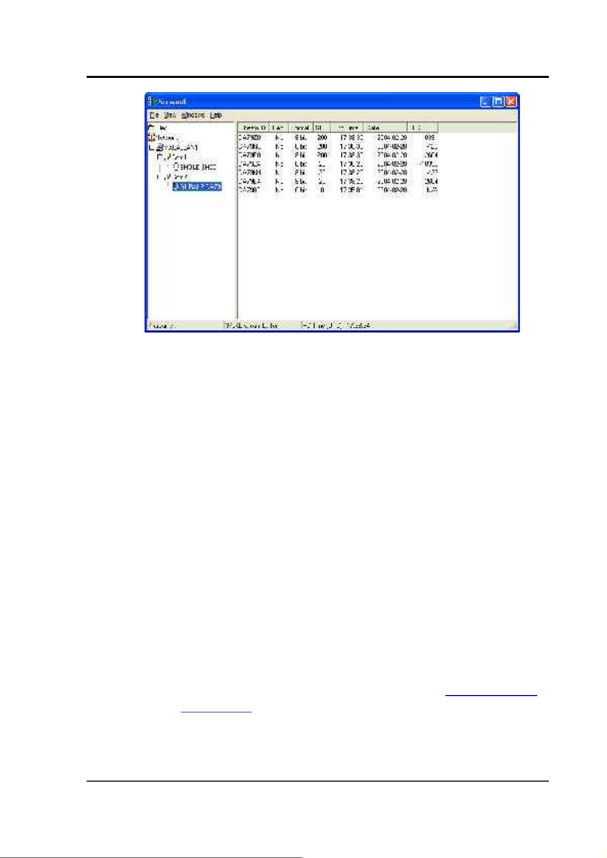
Every checked box in this window will give rise to a data stream coming
from the digitiser, which will be displayed in Scream!'s main window
when Scream! first receives some data from it. Every stream is identified
by a 6-character code, where the first four characters identify the
digitiser, and the last two characters identify the individual stream.
Using the example above, there are three data streams, Z, N and E,
which each output data at 20 samples/s (continuously) and 200
samples/s (occasionally). The streams appear in Scream!'s main window
like this:
18 Issue B
Page 19
CMG-DM24S12AMS Operator's guide
In this example:
• DA79 is the serial ID of the digitiser.
• Z0, N0, E0 correspond to input channels Z, N, and E, output
through Tap 0.
• Z4, N4, E4 correspond to input channels Z, N, and E, output
through Tap 2. A six-channel digitiser connected to two triaxial
instruments will use Z0, N0, E0, Z1, N1, E1 for tap 0; Z2, N2, E2,
Z3, N3, E3 for tap 1; Z4, N4, E4, Z5, N5, E5 for tap 2; and Z6, N6,
E6, Z7, N7, E7 for tap 3. The digitiser in the example has only one
triaxial instrument connected to it, so Z/N/E1, 3, 5 and 7 are
unused.
You can change these designations if you wish: see the Scream!
manual or online help for more details.
• 00 is the digitiser status stream (notice: no sample rate),
• M8, M9, MA are slow-rate Mux channels reporting the sensor
mass positions for the Z, N, and E components (“Mux Channels”
in Section 3.1).
• ME is another Mux channel, here used for reporting the
temperature.
March 2004 19
Page 20

CMG-DM24S12AMS Operator's guide
Triggering
In its standard configuration, the digitiser modules inside the
DM24S12AMS output continuous data at a sample rate you specify. In
addition to this, the digitiser can run a triggering algorithm on the data
it acquires. This allows you to record data continuously at a relatively
low sample rate, but record at a much higher sample rate during short
periods when the trigger is active. The parameters controlling the
triggering algorithm, and controlling the data output once the system is
triggered, are all selectable by the user, permitting maximum flexibility
of operation and the most efficient use of available storage space.
The digitiser modules inside the DM24S12AMS can be set up for
triggered output, that is, to output certain data streams only when a
particular trigger criterion is met. The trigger criterion can be tested with
data from the same or some other stream. For example, you could use a
later tap (with a lower sample rate) as a trigger for output from an
earlier, more detailed tap. Scream! 4 also allows each digitiser to receive
triggers from other digitisers.
To create a new stream with a trigger, open Scream!'s Digitiser
configuration window for the relevant digitiser, and click on the Output
control tab. In the Output control pane, a tap which gives rise to a
triggered stream has a tick in the lower row of its grid of check-boxes.
You cannot configure the trigger criteria until you have selected at least
one stream to be affected by the trigger.
Once you have decided which streams should be output when the
trigger is activated, you will be able to click on the Triggering button to
describe the trigger condition. Alternatively, click on the Triggering tab
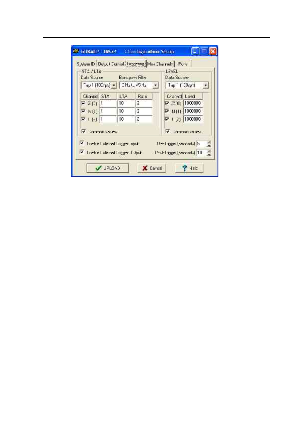
at the top of the window. Either action will open the Triggering pane:
20 Issue B
Page 21
CMG-DM24S12AMS Operator's guide
There are two triggering algorithms which Güralp digitisers can use.
However, not all models can use both methods. Scream! will find out
from the digitiser whether its on-board software supports each method.
STA/LTA
The STA/LTA algorithm applies a simple short-term average – long-term
average calculation to the triggering stream. It works by identifying
sections of an incoming data stream when the signal amplitude
increases. The purpose of taking a short term average, rather than
triggering on signal amplitude directly, is to make it less likely that
spurious spikes will trigger the device. Averaging also introduces an
element of frequency selectivity into the triggering process.
You can select which tap is tested for the trigger from the Data source
drop-down menu. The tap does not have to output data to Scream! for
you to be able to use it here.
Any or all of the channels available at that tap may be used to determine
a trigger. You can select which channels are considered by checking the
boxes in the Channel column of the table. If any of the checked channels
passes the trigger condition, the trigger will activate, and will not
detrigger until all of the checked channels have fallen below their
respective ratio values.
March 2004 21
Page 22

CMG-DM24S12AMS Operator's guide
The STA and LTA columns allow you to set the intervals over which the
two averages are calculated, in seconds. Typically, the time interval for
the short term average should be about as long as the signals you want
to trigger on, while the long term average should be taken over a much
longer interval. Both the STA and LTA values are recalculated
continually, even during a trigger.
The Ratio column determines by what factor the STA and LTA must
differ for the trigger to be passed. Finding the ratio most suited to your
needs is best done by experiment. Too high a value will result in events
being missed, while too low a value will result in spurious non-seismic
noise triggering the system. Like the averages, their ratio is continuously
recalculated for all components. Note that none of the boxes are allowed
to be empty, and so you will need to enter the new value before
removing the old one. Alternatively, you can use the up and down
cursor keys to change the values.
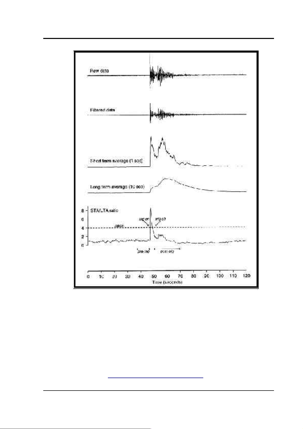
For example, setting the STA to 1 second, the LTA to 10 seconds and the
Ratio to 4 would give rise to the following trigger behaviour:
22 Issue B
Page 23
CMG-DM24S12AMS Operator's guide
Usually, the values of the STA and LTA periods, and of the Ratio, will
be the same for all checked channels. For convenience, Scream! will
automatically fill in other values to match ones you enter. If you want to
use different values for some channels, you should uncheck Common
values before altering them.
Once you have enabled the STA/LTA triggering method on a particular
channel, you can use the Control window to change the values of the
STA and LTA periods, together with the Ratio, without restarting the
digitiser (see Section 3.2, “Controlling digitisers”.)
March 2004 23
Page 24

CMG-DM24S12AMS Operator's guide
Since it is not generally advisable to trigger from broadband data, the
digitiser provides a set of standard bandpass filters to apply to the data
streams before they are tested for the trigger condition. This filtering
serves to maximise sensitivity within a the frequency band of interest,
and filter out noise outside this band. You can select which bandpass
filter to use from the Bandpass filter drop-down menu. The corner
frequencies of the pass band of the filter are determined by the Nyquist
frequency, which is given by the sampling rate of the triggering data.
The three filter options have pass bands between 10 % and 90 %,
between 20 % and 90 % and between 50% and 90% of the data’s Nyquist
frequency, respectively.
The possible filter configurations are shown in the following table:
Tap #
Rate
(samples/s)
Bandwidth 1
(Hz)
Bandwidth 2
(Hz)
Bandwidth 5
(Hz)
0 200 10 – 90 20 – 90 50 – 90
1 100 5 – 45 10 – 45 25 – 45
50 2.5 – 22.5 5 – 22.5 12.5 – 22.5
40 2 – 18 4 – 18 10 – 18
25 1.25 – 11.25 2.5 – 11.25 6.25 – 11.25
20 1 – 9 2 – 9 5 – 9
2 50 2.5 – 22.5 5 – 22.5 12.5 – 22.5
25 1.25 – 11.25 2.5 – 11.25 6.25 – 11.25
20 1 – 9 2 – 9 5 – 9
10 0.5 – 4.5 1 – 4.5 2.5 – 4.5
8 0.4 – 3.6 0.8 – 3.6 2 – 3.6
5 0.25 – 2.25 0.5 – 2.25 1.25 – 2.25
4 0.2 – 1.8 0.4 – 1.8 1 – 1.8
2 0.1 – 0.9 0.2 – 0.9 0.5 – 0.9
3 25 1.25 – 11.25 12.5 – 11.25 6.25 – 11.25
10 0.5 – 4.5 1 – 4.5 2.5 – 4.5
5 0.25 – 2.25 0.5 – 2.25 1.25 – 2.25
4 0.2 – 1.8 0.4 – 1.8 1 – 1.8
24 Issue B
Page 25

CMG-DM24S12AMS Operator's guide
Tap #
Rate
(samples/s)
Bandwidth 1
(Hz)
Bandwidth 2
(Hz)
Bandwidth 5
(Hz)
2 0.1 – 0.9 0.2 – 0.9 0.5 – 0.9
1 0.05 – 0.45 0.1 – 0.45 0.25 – 0.45
As can be seen, the filter you choose defines the set of permissible
sample rates.
The spectral amplitudes for the various frequency responses available
are shown in the following figures.
March 2004 25
Page 26

CMG-DM24S12AMS Operator's guide
Level
Using the Level triggering method, a trigger is generated whenever one
of the checked components reaches a certain level above the baseline.
You can select which tap is monitored from the Data source drop-down
menu, and the channel(s) to be considered from the Channel column of
the table. The values in the Level column are the number of counts
above the baseline that channel must reach before a trigger is generated.
If you wish, you can apply a bandpass filter to the incoming data (see
above) before checking whether it has reached the trigger level.
As with the STA/LTA method, the values of the Level will often be the
same for all checked channels. If you want to use different values for
some channels, you should uncheck Common values before altering
them.
Once you have enabled the Level triggering method on a particular
channel, you can use the Control window to change the level at which
the system triggers without restarting the digitiser (see Section 3.2,
“Controlling digitisers”.)
External triggering
When a digitiser triggers, it sends the trigger itself to Scream! as well as
any extra data that it has been configured to record. Scream! can then
pass on the trigger to other connected digitisers. As an example,
consider an installation similar to that depicted in the Introduction
(overleaf).
Here, a ground sensor attached to one of the ports DIGITAL A – F is
being used to monitor local seismic activity, whilst 12 uniaxial sensors
distributed through a building are measuring its response to ground
movements. These 12 sensors are attached to the analogue inputs CH 1 –
12 on the DM24S12AMS unit.
When a seismic event occurs at the ground sensor, it will trigger. This
trigger needs to be passed on to the CMG-5U sensors (via Scream!) so
that the building's response can be measured accurately. Newer 5TD
units and the DM24S12AMS's internal digitisers support this facility. To
configure the above installation, you would carry out the following
procedure:
26 Issue B
Page 27

CMG-DM24S12AMS Operator's guide
1. Open the Configuration setup window for the digital sensor, and
check Enable External Trigger Output to make it send triggers to
Scream!.
2. UPLOAD the new configuration to the digital sensor.
3. Open the Configuration setup window for one of the
DM24S12AMS's internal digitisers, and check Enable External
Trigger Input to make it listen for triggers coming from the
digital sensor via Scream!, and record data when it receives one
(depending on its Output control configuration.)
4. UPLOAD the new configuration to the internal digitiser.
5. Repeat for the other internal digitiser.
March 2004 27
Page 28

CMG-DM24S12AMS Operator's guide
If a digitiser has both Enable External Trigger Output and Enable
External Trigger Input selected, it will record data when it receives a
trigger from Scream! as if it had triggered itself, but it will not report that
trigger back to Scream!. It will only send a trigger to Scream! if its own
triggering criteria are satisfied.
Note that Scream! must be up and running for external triggering to
work. If you shut down the internal PC, you will need a copy of Scream!
running on a connected network to pass on trigger signals. Because this
introduces a degree of latency, you should allow a reasonable pretrigger period for high data-rate capture (see below).
Pre-trigger and post-trigger recording
In order to capture all of a seismic event, it is often useful to be able to
record data immediately preceding the trigger. The DM24 has an
internal buffer of some seconds which allows this data to be added to
the triggered stream. Pre-trigger data is particularly useful for
emergent-type signals, where the system does not trigger until one
phase after the first arrival.
In addition, to ensure that the coda of each event is included, some
seconds of data are recorded after the system detriggers. In the example
diagram above, the system detriggers well before the event has finished,
so a post-trigger value of 20 seconds is used to capture the remainder of
the event. The example also uses a pre-trigger period of 10 seconds.
The two boxes at bottom right of the Triggering pane allow the user to
set the pre-trigger and post-trigger data intervals, in seconds. These
values determine the minimum length of time during which data will be
saved before the trigger condition occurs, and after it has lapsed.
Regardless of the intervals chosen, the data in the triggered streams will
begin on an even second.
28 Issue B
Page 29
CMG-DM24S12AMS Operator's guide
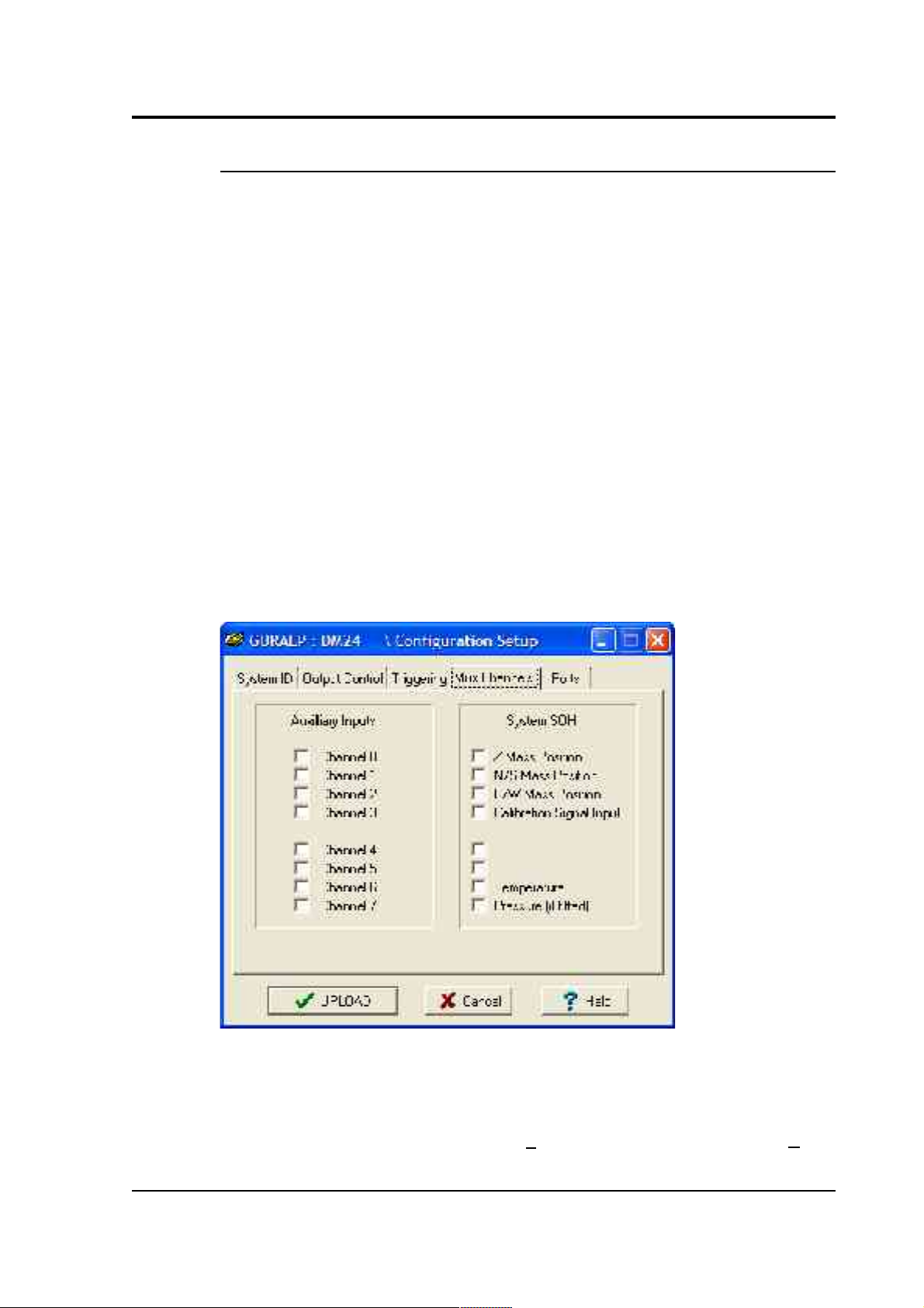
Mux Channels
Units based on the CMG-DM24 digitiser provide a range of 16-bit, 4 Hz
auxiliary channels for reporting the system's state of health and other
diagnostic information, known as multiplexed (“Mux”) channels.
In the stand-alone configuration, three of these are used to report the
sensor mass position, another for receiving calibration signals, and a
fifth for measuring the internal temperature of the digitiser. There are a
further three channels available at the time of manufacture for userspecified optional features, such as pressure monitoring, borehole
orientation, etc., making eight factory-set Mux channels in all.
In addition to these, each digitiser provides eight Mux channels for the
user's own purposes. Mux channels for both internal digitisers can be
accessed through the DM24S12AMS's AUXILIARY port.
The collection and transmission of these environmental channels is
controlled using the Mux Channels pane:
If a tick is placed in the box next to a channel, its data will be collected
and transmitted as a data stream in GCF format, just as with the normal
data channels. To indicate that the data comes from a Mux channel, the
Stream ID will take the form ****Mx, where M stands for Mux and x is
March 2004 29
Page 30
CMG-DM24S12AMS Operator's guide
a hexadecimal integer (i.e. 0 – 9 and A – F for 10 through 15). If a Güralp
digital instrument is attached to a DIGITAL A – F input, the Z, N/S and
E/W Mass Position Mux channels appear as M8, M9 and MA respectively.
The unit's built-in DM24 digitisers do not report mass positions,
although you can access the user-defined channels 0 – 7 for both
through the AUXILIARY connector on the casing. Digitisers also
monitor their internal temperature, which is reported on channel ME.
Ports
Scream! can normally auto-detect the settings it needs to communicate
with any instruments you connect to the DM24S12AMS. However, if
you connect a digitiser to the unit through a telemetry link or a Güralp
Storage and Acquisition Module (SAM), you may need to set the baud
rate and other COM port parameters to match those of the link or
module you are using.
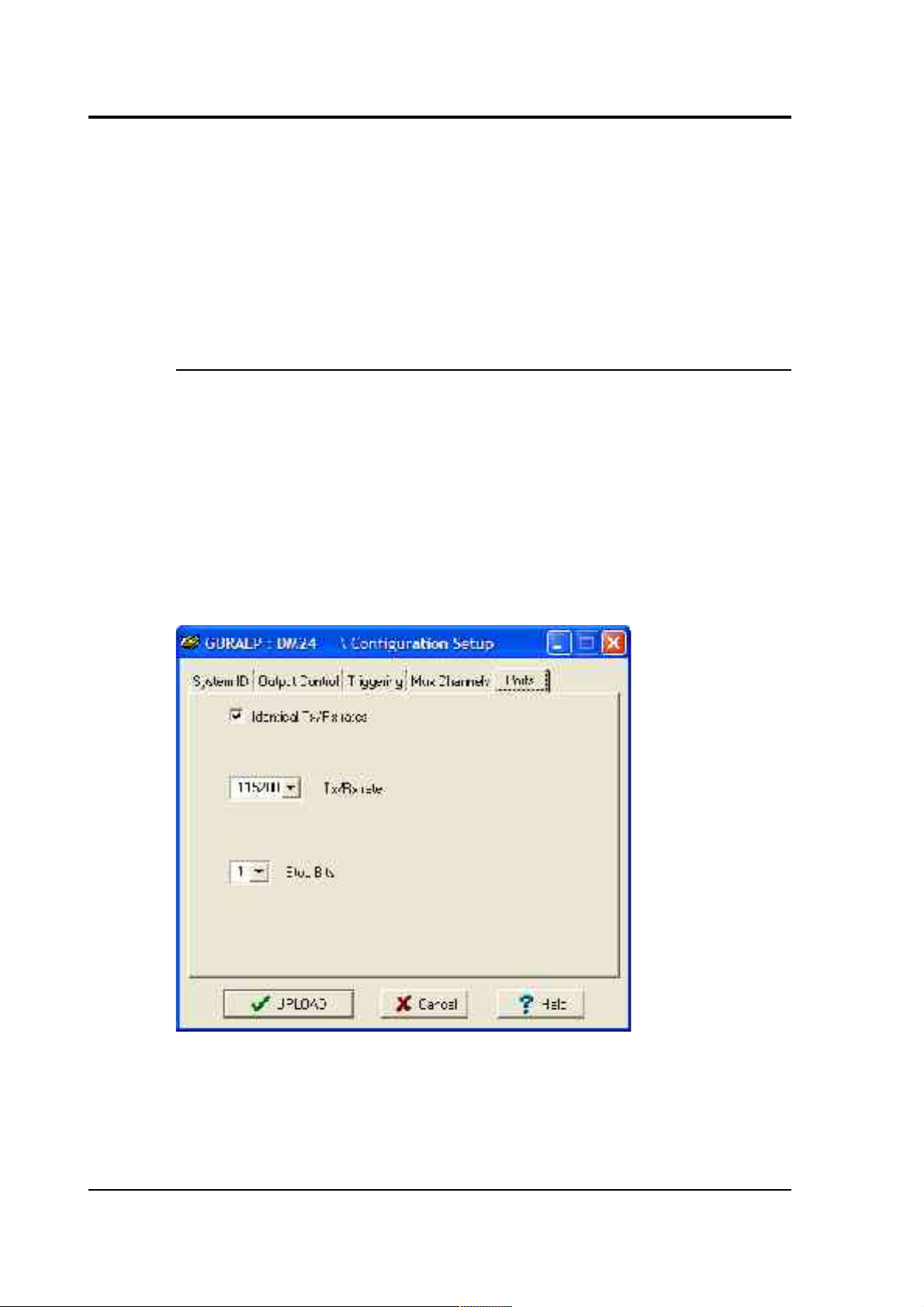
The Baud Rates pane of the Configuration setup window allows you to
program the baud rate and stop bits for the digitiser's COM port.
30 Issue B
Page 31

CMG-DM24S12AMS Operator's guide
The baud rate you choose must satisfy two conditions:
• It must be high enough to allow all the transmission of all data
generated by the digitiser at the sampling rates you have chosen.
For three streams of data at 100 Hz, for example, 9600 baud will
usually be sufficient. If you wish to transmit 200 Hz data,
however, the baud rate must be at least 19200.
• It must be low enough to fit within the operating range of the
telemetry equipment you are using. While modern modems often
offer transfer rates up to 56 kbaud, the telephone or transmission
lines may not support these rates. The same holds true for radio
telemetry.
Usually, the transmit and receive rates of the data port will be the same.
If not, you may select different data rates by removing the check in the
box marked Identical TX/RX rates.
The Stop Bits option allows you to choose whether the serial link uses 1
or 2 stop bits. In most cases this can be left at 1, although 2 may be
required if you are sending data over ‘difficult’ transmission lines (for
example, some types of radio link.) Using 2 stop bits will add a 10%
overhead to the data.
You will also need to set the data rate for Scream's local Com port, as
well as for the SAM/DCM or other communications device (if you are
using one). In Scream!, you can configure a Com port by right-clicking
on its icon (not that of the digitiser) and selecting Configure... from the
pop-up menu: for more details, consult the online help or user guide for
Scream!. If you are using an additional communications device, you
should consult its documentation to learn how to set its baud rate.
March 2004 31
Page 32

CMG-DM24S12AMS Operator's guide
3.2 Controlling digitisers
To control a digitiser whilst it is running, either right-click on the
digitiser's entry in the list to the left of Scream!'s main window (not the
Local or Comxx icons) and click Control..., or simply double-click the
entry. Scream! will then contact the digitiser and retrieve its current
status, a process which will take a few seconds, after which the Control
window will be displayed. Once you are happy with any changes you
have made in the Control window, click Apply to send them to the
digitiser, where they will take effect immediately.
This chapter describes the control options available to you for the
DM24S12AMS's built-in digitisers. Many of these options will also be
available for other Güralp digitisers or digital sensors connected to the
unit's DIGITAL A – F ports. For the most accurate information, you
should consult the Operator's Guide for the digitiser or sensor you
connect.
System
When the Control window is first opened, it will be showing the System
pane.
32 Issue B
Page 33

CMG-DM24S12AMS Operator's guide
Sensor Type: If the sensor attached to the digitiser is a Güralp velocity
sensor, useful seismometer functions (such as sensor locking, centring,
and calibration) may be controlled through the digitiser. The type of
sensor programmed with this option determines which functions will be
available through the SCREAM digitiser configuration set-up interface
or through interactive commands. The in-built digitisers are already
programmed to the proper sensor type for Güralp CMG-5U uniaxial
sensors.
Enable GPS power cycling: If you are using a GPS unit to receive time
signals, but do not experience significant drift in the system's clock (for
example, in a stable-temperature environment), you can save power by
selecting Enable GPS power cycling. With this option in use, the GPS
time is only checked at intervals of a specified number of hours. You can
enable or disable this feature at any time, but if you want to change the
interval between time fixes, you will need to use the Configuration setup
window (and reboot the digitiser.)
Triggering
The Triggering pane is very similar to the corresponding pane of the
Configuration setup window, although not all options are available since
some require rebooting the digitiser. See “Triggering” in Section 3.1 for
more details.
March 2004 33
Page 34

CMG-DM24S12AMS Operator's guide
Calibration
The analogue links between the DM24S12AMS and the sensors must be
calibrated before you can use them, since the strength of the signal they
output can vary. The Calibration pane allows you to do this once the
sensors are installed.
Each channel Z, N/S and E/W can be calibrated separately. For triaxial
digital instruments attached to the DM24S12AMS's DIGITAL A – F
sockets, each channel calibrates the corresponding axis of the
instrument; simply select one of the Z, N/S and E/W check boxes to
calibrate that axis.
The DM24S12AMS's two internal digitisers can also be calibrated. For
the first (“Digitiser A”), the Z channel sends calibration signals to both
CH 1 and CH 2, whilst N/S is connected to CH 3 and CH 4, E/W being
linked to CH 5 and CH 6. For the second (“Digitiser B”), Z calibrates CH
7 and CH 8, N/S calibrates CH 9 and CH 10, and E/W calibrates CH 11
and CH 12.
The sensors respond to calibration signals on the Mux channel ME.
The Duration box tells the digitiser how long to provide the calibration
signal before disconnecting. This avoids the system being inadvertently
34 Issue B
Page 35

CMG-DM24S12AMS Operator's guide
left in calibration mode. The default is 2 minutes. If you change this
setting, it will revert to the default value after one calibration stage.
The digitiser can produce either sine-wave or square-wave (step)
calibration signals. The Sine wave calibration signal always starts and
stops on the zero crossing. The frequency or period given by the boxes
at bottom left. Only integers between 1 and 10 may be specified for
either frequency or period, so to generate a 0.5 Hz signal you should
select Period and set the time to 2 (seconds). Likewise, if you require a
0.25 second period you should select Frequency and set the rate to 4
(Hz). In this manner, you can select frequencies ranging from 0.1 to 10
Hz (10 to 0.1 s periods).
Alternatively, you can specify step calibration by selecting the Square
wave button. The square wave consists of a positive step at the start of
the next minute of the digitiser’s internal clock, followed by a negative
step after a specified number of minutes. After a further delay of the
same number of minutes, the calibration signal is disconnected. The
default is 2 minutes.
Data Flow
March 2004 35
Page 36

CMG-DM24S12AMS Operator's guide
The Data Flow pane of the Control window allows you to instruct the
digitiser what to do with data that it receives. Many Güralp digitisers
contain internal Flash memory, which can be used to store incoming
data if requested. The DM24S12AMS's internal digitisers do not contain
internal Flash memory, since they are set up to transmit directly to the
built-in laptop (which has a much greater storage capacity.) However,
you may want to use these options if you have connected another
Güralp digital instrument to one of the DIGITAL A – F ports. For more
information, please consult the documentation for the instrument you
connect.
3.3 Recording and filing data
Scream! allows you to record all incoming data and store it on the local
hard disk. To do this, you should select the streams you want to record
from Scream!'s main window, right-click, and choose Start recording
from the pop-up menu. The streams will display Yes in the “Rec”
column to indicate that they are recording.
By default, recorded data is placed in a data directory within the
Scream 4 installation, in GCF format.
Scream! has a number of options which allow you to change the way
data is recorded and filed. From the main window, select Setup... from
the File menu to open the Setup window. Click on the Recording tab.
(Scream!'s setup window also provides a number of other kinds of
options. Consult Scream!'s documentation or online help for more
details.)
Recording
The upper part of this pane allows you to instruct Scream! to record
various streams automatically. Scream! will start recording all relevant
streams immediately, but will also remember the settings for the next
time it is started up.
Auto Record—Enable for Data Streams causes all local data streams to
be saved automatically, whilst Auto Record—Enable for Status Streams
does the same for digitiser status streams (those ending in “00”.)
36 Issue B
Page 37

CMG-DM24S12AMS Operator's guide
Auto Record uploaded streams tells Scream! to record streams it
receives over the network. These are not normally counted with the
streams above, since they may come from another Scream! which is
already recording.
Auto-upload on heartbeat tells Scream! to attempt to fetch extra data
from digitisers which are storing it in their own Flash memory
whenever possible, so that it can fill in gaps in the data it is recording.
The DM24S12AMS's built-in digitisers do not have any internal Flash
memory, so this option will only have an effect for digital instruments
connected to the DIGITAL A – F ports.
The lower section tells Scream! how to use its hard disk space. If Stop on
Disk Full is selected, then Scream! will stop recording data once it runs
out of space in its directory. This way, the data recorded will have a
known starting point. If you select Ring Buffer, then Scream! will start
deleting the oldest files in the data directory in order to make space for
new data, so that you will always have access to the most recent
recorded measurements. Note that Scream! does not check whether it
created the files itself. If you put your own files in Scream!'s data
directory, then they are at risk of being deleted.
If there is very little space on the disk, the PC's operating system can
become slow or unstable. By default, Scream! will consider the disk
March 2004 37
Page 38

CMG-DM24S12AMS Operator's guide
“full” when only 50 Mb of space remains on it. You can change this
amount by altering the value at bottom right.
Files
Another part of the Setup window allows you to alter the way Scream!
files the data it receives. Click on the Files tab to open the following
pane:
The options you can change are:
Base Directory: This specifies the root directory in which data files will
be saved. Files for each stream are stored in sub-directories off this root.
The sub-directory structure depends on the filename format.
Filename format: This allows you to describe how you want files to be
named by entering a format specifier. The string you enter is used to
construct the file names for all files. Among the specifiers you can use
are:
YYYY the year number (e.g. 2003),
M the month number (1 – 12),
D the day of the month (1 – 31),
38 Issue B
Page 39

CMG-DM24S12AMS Operator's guide
H the hour (0 – 23),
N the minute (0 – 59),
S the second (0 – 59),
R or J the day in the year (0 – 366),
X the date represented as an 8-digit hexadecimal number (this allows a
complete date to fit in the DOS 8.3 format, for compatibility),
I the system ID (e.g. TEST),
T the stream ID (e.g. DMZ2),
C the component identifier (Z,N,E,M, etc.),
P the sample rate, in samples per second.
The specifiers MM, DD, HH, NN, SS, RRR, JJJ, IIIIII and TTTTTT are
the same as their single-letter counterparts, but they are padded with
zeros or underscores to a constant length. YY can also be used for a 2digit abbreviation of the year (e.g. 03 for 2003.)
Any other letters (including small letters) in the filename will be left as
they are, so you can add constant descriptions or field separators as you
wish. Owing to operating system limitations, you cannot use any of the
punctuation marks * ? " : < > | in filenames. You can create directory
structures by using the \ character.
For example:
T\YYYY_MM_DD;HHhNNmSSs will give filenames like
dmz2\1997_10_05;07h35m20s.
Data Format: Selects the format of the recorded data files. Options are
GCF, SAC, MiniSEED, P-SEGy, PEPP, SUDs, GSE, UFF (ufa and ufb; see
below), and CSS.
Byte Order: For SAC, SEG-y, UFB and CSS files, the byte order of the
files can be specified. This can be used to match the byte order with the
native order of the platform where you are going to perform analysis.
March 2004 39
Page 40

CMG-DM24S12AMS Operator's guide
GCF and MiniSEED are defined to be in “Motorola or SPARC” byte
order. PEPP and SUDs data is defined to be in “Intel” byte order. Byte
order is not applicable to the ASCII-like GSE or UFA formats.
Granularity: Allows you to decide how large files are allowed to
become before a new one is started, for three different types of stream
(high sample rates, low sample rates and status streams.) The distinction
between high and low sample rates is set by the number in the Sample
Rates >= box. The remaining boxes give how many hours of data should
be combined into a single file for each type of stream.
If you prefer to set a limit on a file's size, rather than its duration, choose
Kilobytes from the drop-down menu (instead of Hours) and set as
appropriate.
Post-processor: This option allows you to specify a program which
Scream! will run every time it closes a file. The name of the file is passed
as a parameter. You can use this feature to interface to other analysis or
archival systems, for example:
• FTP or emailing files to remote data centres,
• format conversion using a third party utility,
• post-processing of file data headers to add site-specific
information.
The UFF file format
The DM24S12AMS unit is specially configured to record files in the
Universal File Format (UFF) in dataset 58 structure (Function at Nodal
DOF). Two types of UFF format are supported: ASCII and binary, where
the extension ".ufa" denotes the ASCII variant, and ".ufb" denotes the
binary variant. The byte order used for the binary variant is specified in
the Recording pane of the Setup window. ASCII does not have byteordering options. Details for the layout of the UFF format can be
obtained from the University of Cincinnati at
http://sdrl.rhod.uc.edu/UFF2/
40 Issue B
Page 41

CMG-DM24S12AMS Operator's guide
Recording in UFF format
You can instruct Scream! to record incoming data directly in UFF
format. To do this, open the Files pane of the Setup window as above
and select either UFF ASCII (.ufa) or UFF Binary (.ufb) in the Data format
drop-down menu. However, since UFF files tend to be large and do not
contain all the data gathered by the sensor, it is recommended that you
keep the initial recording in GCF format, and convert to UFF as required
using the tools provided (see below).
Files in UFF format must represent a continuous period of time. If a
discontinuity is detected in the incoming data stream, then the file which
is currently recording will be closed, and a new file opened with a
filename time stamp matching the start of the new file. This operation
will take place whatever options you have specified for Granularity,
although the Granularity options will still work. For example, if you
specify files lasting one hour, a new file will be opened on the hour,
every hour, whether or not a discontinuity occurred during the previous
hour (which will have caused a new file to be opened at that point).
Converting between UFF and other file formats
On occasion, you may need to convert files between the various data
formats supported by Scream!. For example, you may want Scream! to
record data in GCF format and convert it to UFF later, to ensure that
you retain all the data received from the sensors. The most convenient
way to convert a GCF file into UFF format is using the command-line
tool gcf2asc, available from Güralp Systems' website at
http://www.guralp.com/. Once the program is installed, you can convert
files from a command window (click on Windows Start – Run... and
type cmd<enter>). The command to issue is
gcf2asc your-gcf-file.gcf /uff where your-gcf-file.gcf
should be replaced with the correct filename.
By default, gcf2asc will create a file with the same name as the
original, but with a .txt extension; you may want to rename the file
produced to have a .uff or .ufa extension. Any time periods missing
from the GCF file are represented by values of –2147483647 (the lowest
possible negative number in the GCF format).
March 2004 41
Page 42
CMG-DM24S12AMS Operator's guide
You should ensure that you have enough space to create a UFF file
before running gcf2asc. UFF ASCII files are typically around 10 times
larger than the equivalent GCF file.
3.4 Networking
You can access the data coming from the DM24S12AMS from anywhere
on a local or remote network through its on-board laptop PC. The USB
and NETWORK ports on the casing connect directly to the laptop's USB
and Ethernet interfaces, whilst the TELEPHONE socket is connected to
an internal modem. Any of these can be configured through the
Windows XP Control Panel.
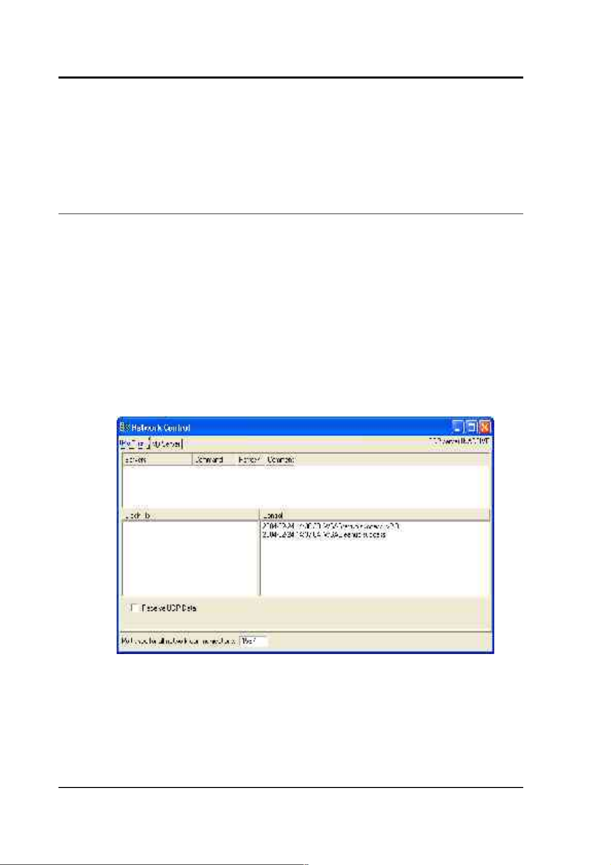
Once a network connection is set up, Scream! can act as a server to
provide data to other computers running Scream! or archival programs.
To view the currently active Scream! network connections, select
Network Control from the Window menu of the main window:
42 Issue B
Page 43

CMG-DM24S12AMS Operator's guide
My Client
As a client, Scream! receives blocks of data inside UDP packets, which are
shown in the Block Rx pane. UDP does not guarantee that data will be
successfully received. If data is lost and subsequently recovered, a
diagnostic message will appear in the Control pane. (Scream! is also able
to open TCP connections, but these are designed for direct serial links,
and will generally not allow two computers running Scream! to
communicate.)
Scream! servers can be set to push data onto the network (i.e. to
broadcast it to all listening clients), or to wait for data to be pulled from
other Scream!s on the network. To receive data from a Scream! server
that is pushing data, simply check the `Receive Data' box. No other
action is necessary.
If you need to pull data from the server, you should use the following
procedure:
1. If it is not already selected, check Receive Data to start Scream!
listening.
2. Right-click anywhere in the Servers list box, and select Add UDP
Server.... Enter the IP address and port number on which the
server is waiting for requests, separated by a colon : (e.g.
192.168.42.98:1567)
3. Test communications by right-clicking on the newly-added
server, and selecting GCFPING. A message appears in the
Control pane logging the ping being sent. If communication is
good, and the server is enabled for client requests, you will
receive a GCFACKN message from the server which will also
appear in the Control pane.
4. Request data by right-clicking on the server and selecting
GCFSEND:L (or GCFSEND:B) from the pop-up menu.(L is used
for little-endian and B for big-endian byte order, and are
distinguished for compatibility.) Streams should soon begin to
appear in Scream!'s main window.
5. To stop the link, right-click as before and select GCFSTOP from
March 2004 43
Page 44

CMG-DM24S12AMS Operator's guide
the pop-up menu. If you do not GCFSTOP, the server will
continue to transmit to a client that is no longer listening. You
should ensure that the server replies with a GCFACKN message If
an acknowledgement does not appear in the Control pane, repeat
the GCFSTOP command.
The steps above can be repeated as many times as necessary to pull data
from several servers, but care should be taken to GCFSTOP each one
before terminating the application.
My Server
Scream!'s server can transmit blocks of data acquired from local
instruments over the network via UDP. The list of clients that are
currently being sent data is shown in the Clients table at the top of the
window. Block-by-block details of the data being transmitted are
indicated in the Block Tx pane. Other server operations are logged by
messages in the Control pane to its right.
Scream! can either push data to a network device or wait for it to be
pulled off it. The server can behave in different ways for different clients.
You can see which clients are using which method by looking in the
Timeout column: pushed clients have a timeout value of 0, whilst
pulling clients have some other timeout value (after which, if nothing is
heard from them, they will be removed from the list.)
44 Issue B
Page 45

CMG-DM24S12AMS Operator's guide
To start the server, check the Transmit data from local Com Ports box.
This applies to both push and pull type data transfer.
You can add client to push data to by right-clicking in the Clients list box
and selecting Add. Type in the IP address and port number of the
destination, separated by a colon :. Many destinations or broadcasts may
be added, and data will be sent to each one simultaneously.
You can broadcast data to all connected computers by using the IP
address 255.255.255.255. To restrict broadcasts to a particular subnet, use
255 as a wild card: for example 192.168.255.255:1567 will broadcast data
on port 1567 to all clients whose IP addresses begin with 192.168. To
send data to another Scream! running on the same computer, use the IP
address 127.0.0.1.
The x sps transmitted block limit sets a ceiling on the sample rate of
data for transmission. This is useful if your network connection is slow
or congested, since it limits the amount of data Scream! sends. The
default value is 200 (effectively, all data). As an example, if a digitiser is
configured to generate 4 samples/sec and 100 samples/sec continuous
data, you could monitor the data remotely over a low-bandwidth
network, whilst still recording the 100 samples/s data, by setting this
value somewhere between 4 and 100. Setting this value to zero
suppresses all data, but still transmits status information.
Scream! can act as a conduit from a network connection to any device
connected to a local serial port. To enable this, select Allow remote
access to Com Ports. If you wish to change the configuration of the
equipment remotely, you should enable this option. If you are
concerned about security, or there are potential problems from outside
interference, disable this option.
3.5 Upgrading firmware
The built-in digitisers of the DM24S12AMS carry their on-board
software in Flash memory, so that the user can upgrade it as new
versions become available. These are posted from time to time on the
Güralp Systems website and announced on the Scream! users' mailing
list. To subscribe, send an email to listserver@guralp.com with the
single line in the body:
subscribe screamusers
March 2004 45
Page 46
CMG-DM24S12AMS Operator's guide
To find out what software version you are currently using, right-click on
the digitiser’s icon (not the Local or the Comxx icons) in Scream!'s main
window and select Configure from the pop-up menu. This will open the
Configuration setup window.
If you are running an older version of the digitiser software, and wish to
upgrade, you should first obtain the latest software from Güralp
Systems, then proceed as follows.
In Scream!’s main window, right-click on the digitiser’s icon and select
Terminal from the pop-up menu to open a terminal window. Check that
there is two-way communication with the digitiser by pressing Enter.
The digitiser should reply with ok on a new line.
46 Issue B
Page 47
CMG-DM24S12AMS Operator's guide
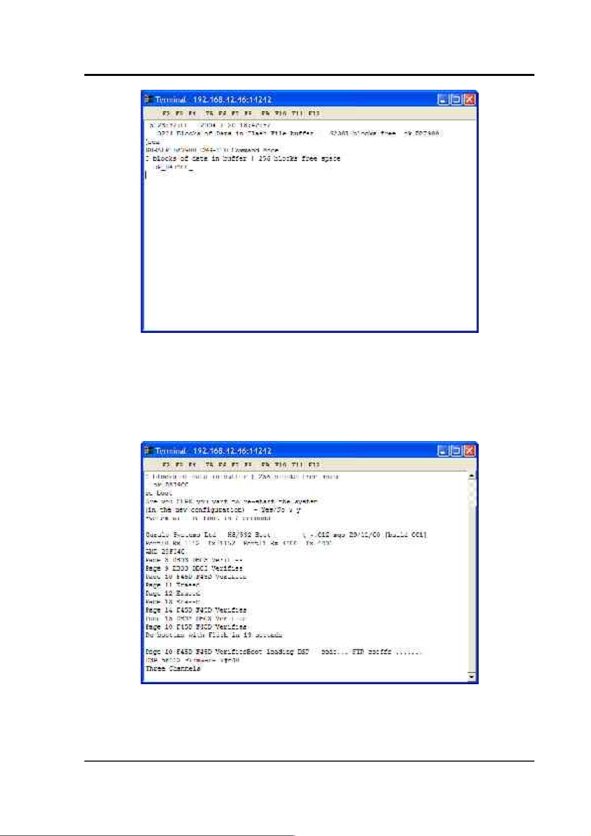
Type re-boot to reinitialize the digitiser, and confirm with y. The
initial boot-up information will be displayed, similar to that shown in
the picture below. After a short while, the digitiser will pause. If you do
not enter a command in the next 13 seconds, the digitiser will continue
booting up normally.
To update the firmware, type h8upload during the pause and press
Enter. Once the message Ready to upload has appeared, right click
anywhere on the terminal window and select Send file from the menu:
March 2004 47
Page 48

CMG-DM24S12AMS Operator's guide
Navigate through the directories on your computer and select the file to
be uploaded, or type in its full path and file name. Click Open.
Whilst the file is loading, a progress window will be displayed. Once the
software is fully transferred, the old installation will be backed up and
the new one put in place. This will take a couple of minutes, after which
you should type re-boot to restart the digitiser with the new firmware.
48 Issue B
Page 49

CMG-DM24S12AMS Operator's guide
3.6 GPS
All Güralp digitisers have a separate stream for reporting information
about the system, such as their GPS and time synchronization status.
This status information is in plain ASCII text format.
To see a Status window for any digitiser, right-click on the Stream ID
xxxx00, (where xxxx is the ID of the digitiser). In the example below
this is 102600. This is the only stream with a reported rate of 0
samples/s.
During boot-up each unit reports its model type, firmware revision
number, the system ID and serial number. This information is followed
by the number of resets that have occurred and the time of the latest
reboot from its internal clock. The following lines report the current
configuration of the unit's sample rates, output taps, and baud rates. A
typical digitiser re-boot status message looks like this:
March 2004 49
Page 50

CMG-DM24S12AMS Operator's guide
The system will produce this status message whenever it is powered up.
If this status is reported at other times it indicates that the system has
been reset by the built-in watchdog monitor. This will occur if the
system has suffered corruption as a result of external noise or power
dips.
If the digitiser does not have a GPS unit connected for time
synchronisation no further status reports are produced.
If a GPS unit is fitted, its operational status is reported on reboot and the
behaviour of the time synchronisation software will also be shown.
From a cold start, GPS will initially report No GPS time together with
its last position (taken from the internal backup.) All messages from the
GPS that involve a change of its status are automatically reported.
Repeated status messages are not shown to avoid unnecessary clutter.
The initial GPS status report will look like this:
If the GPS receiver is having difficulty locating satellites, there may be a
delay of several minutes before a new message is displayed, but if the
system has not been moved from its previous location it should report
the acquisition of one or more satellites and GPS time fairly quickly. The
report will also show the satellite numbers and their corresponding
signal strengths.
50 Issue B
Page 51

CMG-DM24S12AMS Operator's guide
The internal time synchronisation and control software will wait for the
GPS unit to report a good position fix (this requires 3 satellites) before
beginning. (The system actually waits for good reception of 6
consecutive messages, which normally occur every 10 to 20 seconds.)
If the GPS unit maintains a good fix from the satellites available, the
system will then switch on the control process and set the internal clock.
It will also re-synchronise the Analogue to Digital Converters so that the
data is accurately time-stamped to the new reference. Any data
transmitted up to this point will be stamped with the time from the
internal backup clock, which is set to the new accurate time at the end of
this process. The re-synchronisation will result in a discontinuity in the
data received.
From this point, the control process will continually attempt to keep the
internal time-base synchronised to the GPS 1 pulse per second output by
adjusting its voltage-controlled crystal oscillator. The control algorithm
has two stages: initially it compares its internal 1 Hz timebase with the
GPS signal and adjusts the voltage control to minimise the error. Once
this has been achieved it then controls the crystal to minimise both the
‘phase error’ (i.e. the offset between its internal 1 Hz signal and the GPS)
and the drift (frequency error relative to GPS.) During the control
process the system reports the measured errors and the control signal
applied, as a PWM (Pulse Width Modulation) value.
During the initial, coarse adjustment stage only the coarse voltage
control is used and no drift calculation is made. If the system is
operating in a similar environment to that when the system was last
powered (most importantly, the same temperature) the saved control
parameters will be appropriate and the system should rapidly switch to
the ‘fine’ control mode. The system reports its control status and
parameters each minute, with error measurements given in nominal
timebase units. In a stable temperature environment the system should
soon settle down showing an offset error of only a few thousand
(average error < 100 microseconds) and a drift rate under 100 counts (< 1
in 10-6).
March 2004 51
Page 52

CMG-DM24S12AMS Operator's guide
4 Inside the DM24S12AMS
4.1 DM24S12AMS module
The DM24S12AMS is a complete data acquisition and monitoring
system, with a modular design. The casing contains two independent
CMG-DM24 6-channel digitisers, each of which processes data from six
of the twelve analogue input channels. A separate GPS controller
provides timing information to both digitisers and to any additional
instruments connected to the DIGITAL A − F sockets.
Once in digital (GCF) form, the data is relayed to the built-in laptop PC
where it is received by Scream! and can be recorded or passed on to
other devices as necessary, either through a local network or USB
connection or over a telephone line.
52 Issue B
Page 53

CMG-DM24S12AMS Operator's guide
Power
The power module can convert power supplied from several sources
into a supply suitable for running the system. The same power supply is
normally used for running the DM24S12AMS, the GPS unit, and any
sensors attached to the module. If you prefer, however, you can attach
separate 12 V DC power supplies to any external unit.
Whilst sufficient mains (110 – 230 V) or 12 V DC power is supplied to the
DM24S12AMS, you can also trickle-charge a battery connected to the
BATTERY/UPS socket. To do this, you will need to use a cable which
connects both positive and charging pins of the socket to the same
terminal of the battery (see the Appendices for more details.) For
example, you might want to connect the DC INPUT socket to a solar
array or other intermittent power source, whilst keeping a rechargeable
battery attached to the BATTERY/UPS socket to use when power is
unavailable.
GPS
The CMG-GPS2 Receiver Unit comprises an antenna, the GPS receiver
electronics, wide range input isolated DC power supply and output line
drivers.
The antenna and all the associated electronics above are housed inside a
specially-designed enclosure. The enclosure is sealed with O-rings and
manufactured from a hard rigid resin. It is a stand-alone unit requiring
only one cable connection to the DM24S12AMS, which carries both
signals and power.
March 2004 53
Page 54

CMG-DM24S12AMS Operator's guide
GPS data, including position, date/time and device status, is output in
NMEA format at 4800 baud once per second. A time synchronisation
pulse of 100 ms duration is output at 1 pps (pulse per second). Both
outputs use RS232 (or, optionally, RS422) line drivers, enabling you to
use cables up to 100 metres long.
For information on how to set up a GPS receiver, see Section 3.6, “GPS”.
USB to RS232 converter
Digital channels within the DM24S12AMS (the digital outputs of the
two internal digitisers, and the six DIGITAL A − F are carried over RS232
links to an 8-port EdgePort module, which allows the serial ports to be
emulated over USB. The PC is configured so that the external DIGITAL
A − F ports appear as if they were directly attached, together with two
Com ports for the internal digitisers.
If your installation requires some other setup of the PC's Com ports, you
can configure the EdgePort device using the driver software provided.
Further information can be obtained at the EdgePort documentation
website, http://www.ionetworks.com/support/epdocs.html
4.2 Inside the DM24
Internally, all DM24 digitisers are structured as shown in the diagram
overleaf, where each box represents a separate printed circuit board
within the module. There are two of these modules in the DM24S12AMS
unit, which operate separately.
The system is designed around a low power, high performance Hitachi
H8/500 microprocessor. This is a 16-bit processor with a large address
space for data storage and manipulation—1Mb in sixteen 64k pages. It
also includes many integrated functions such as multiple timers and
serial I/O ports. In addition, the system contains a Crystal
Semiconductor CS5321/2 chipset and Motorola 56002 DSP. The CS5321/2
provides data at 2,000 samples per second, triggered by the H8 timing
system, to the 56002 DSP. The DSP can control from 1 to 3 ADCs and
process the data.
54 Issue B
Page 55

CMG-DM24S12AMS Operator's guide
The modular design of the system takes advantage of the processor's
paged structure: each module is designed to occupy its own separate
page, with a dedicated I/O function. Thus any module can simply be
added to the system at any available page when it is required. Each
module includes 32k of RAM which is used for data buffering and
workspace for the module’s software.
March 2004 55
Page 56

CMG-DM24S12AMS Operator's guide
An important feature of the system design is its ability to synchronise
the sampling of the analogue to digital converter to an external time
reference. This way, data samples are accurately time stamped at source.
To keep sampling accurately in step with UTC, you can synchronise the
microprocessor's time-base to an external reference such as GPS, or in
larger arrays to a centrally-transmitted time reference. Transmitting a
time reference avoids the cost and power consumption of multiple GPS
receivers, and since it only involves sending 2 characters per second it
can utilise a low band-width, even half-duplex link.
To achieve the high degree of timing precision required for a 24 bit
digitiser system, the microprocessor time-base is run from a precision
voltage controlled oscillator. On-board software keeps this oscillator
tuned to the external reference so that its frequency is accurately set and
maintained through changes in temperature or ageing. Once the system
has stabilised, the control is sufficiently accurate to maintain precision
sampling for several hours without an external reference. The system
also automatically compensates for the pure time delay introduced by
the digital filtering/decimation processes in the DSP.
The main microprocessor board incorporates a battery-backed real-time
clock and RAM which is used to set the system's internal software clock
at start-up independent of the availability of the external time reference.
The RAM is used to store system parameters such as the optimum
control voltage setting for the system time-base and the system
configuration.
The microprocessor module includes the (multi-tasking) system
operating software in 64K EPROM. This module also has 512k of static
RAM for system workspace and data buffering depending on the
system requirements (number of data channels and sample rates).
The microprocessor serial port (19,200 Baud) provides an interactive
interface for system setup and configuration. This port is known as the
terminal port. Unlike the GPS serial port or the data port, the terminal
port is not optically coupled to the outside world. Care should be taken
not to run a terminal over very long RS232 cables.
The DSP software consists of 4 cascaded programmable
filter/decimation stages, which allow you to select multiple data output
rates simultaneously. The first stage is set to decimate the data by 10
56 Issue B
Page 57

CMG-DM24S12AMS Operator's guide
resulting in a data output rate of 200 samples/sec. The following 3 stages
can be set individually for decimation factors of 2, 4, 5, 8, and 10
allowing data to be output at lower rates requiring less storage and
transmission bandwidth. For example, a system can be configured to
provide data at 200, 50, and 10 samples/sec covering the whole of the
seismological broad band range.
The configuration of the DSP is programmable (in the field) via the host
H8 microprocessor. The H8 communicates with the DSP via its high
speed 8-bit ‘host port’, which allows the operating mode/configuration
to be altered and the resulting processed/filtered data to be acquired.
The primary digital interface for the systems is the multiple serial port
card. Each card can contain 1 or 2 dual UARTs (Universal Asynchronous
Receiver Transmitters) and up to 2 cards can be fitted to a SAM/DM
unit. This allows a system with up to 8 serial ports to be configured.
On a DM unit with analogue inputs a serial port is usually configured to
send the data packets to a (local) SAM unit for storage/acquisition or via
a modem or radio link to the central recording station. The second serial
port is available for use with a local GPS receiver for time
synchronisation, or alternatively the first (data) port is used for time
synchronisation from the central station.
The multiple serial port card is usually configured as several data inputs
for a SAM unit allowing it to collect data from up to 8 other SAM or DM
units located locally, using RS232 or RS422 links, or more remotely
using radio links or telephone modems.
Each of the serial ports on a module can be configured for a wide range
of standard baud rates (with different settings available for transmit and
receive channels), allowing a wide range of data links to be used
depending on the required data rates.
The first dual UART supports full modem interface on one port and
hardware handshake on the second. The second dual UART is
configured for data line interface only, supporting software handshake.
Each dual UART is optically isolated to avoid ground loops that could
degrade the performance of the ADC’s. The serial port module includes
32k of RAM for data buffering and formatting by the
transmission/reception process.
March 2004 57
Page 58

CMG-DM24S12AMS Operator's guide
5 Using CMG-5U sensors
5.1 The CMG-5U accelerometer
The CMG-5U sensor is a single-axis strong-motion force-feedback
accelerometer in a sealed case, which can be used in either vertical or
horizontal orientations. The sensor system is self-contained except for its
10 – 12V power supply, which can be provided through the same cable
as the analogue data. An internal DC–DC converter ensures that the
sensor is completely isolated.
The 5U system combines low-noise components with high feedback
loop gain to provide a linear, precision transducer with a very large
58 Issue B
Page 59

CMG-DM24S12AMS Operator's guide
dynamic range. In order to exploit the whole dynamic range two
separate outputs are provided, with high and low gain. Nominally the
high gain outputs are set to output a signal 10 times stronger than the
low gain outputs.
The 5U sensor outputs are all differential with an output impedance of
47 Ω. A single signal ground line is provided as a return line for all the
sensor outputs.
Full-scale low-gain sensitivity is available from 4.0g down to 0.1g. The
standard frequency pass band is flat to acceleration from DC to 100 Hz
(although other low pass corners from 50 Hz to 100 Hz can be ordered.)
A high frequency option provides flat acceleration from DC to 200 Hz.
Each seismometer is delivered with a calibration sheet showing its serial
number and measured frequency response in both the long period and
the short period sections of the seismic spectrum.
March 2004 59
Page 60

CMG-DM24S12AMS Operator's guide
5.2 Installing CMG-5U sensors
Unpacking and packing
The 5U accelerometer is delivered in a single cardboard box with foam
rubber lining. The packaging is specifically designed for the 5U and
should be reused whenever you need to transport the sensor. Please
note any damage to the packaging when you receive the equipment,
and unpack on a clean surface. The package should contain:
• the accelerometer
• a signal connection cable (if ordered)
• a suitable connector.
The sensor serial number label can be found on the lid of the sensor. If
you need to request the sensor production history, you will need to
quote either the serial number of the sensor or the works order number,
which is also provided on the calibration sheet.
Initial testing
To test the 5U before installation, you will need a power source which
can deliver 100 mA at 10 to 12 V and a digital voltmeter (DVM) with 1
and 10 V ranges. You should never supply more than 12.5 V to the 5U
unit. Also ensure that the supplied cable is connected with the correct
polarity (see the Appendices).
To make it easier to measure the output from the sensor, you can use the
5U handheld control unit or a compromised interface box, which can be
manufactured from a screw clamp connector block. This will simplify
the connections to the appropriate connector pin outputs.
1. Place the 5U sensor on a flat surface with the POSITIVE
ACCELERATION arrow horizontal.
2. Switch on the power supply.
60 Issue B
Page 61

CMG-DM24S12AMS Operator's guide
3. Connect the voltmeter to pins J and K of the output connector
(corresponding to the low gain vertical component.) Measure the
output of the low gain vertical component. The steady output
voltage should be about zero (± 10 mV).
4. Now turn the sensor on its side, so that the POSITIVE
ACCELERATION arrow points upwards.
5. The low gain vertical component should now read about –5 V,
corresponding to –1g.
If the performance so far has been as expected, the instrument may be
assumed to be in working order and you may proceed to install for trial
recording tests. Most likely, however, you will need to adjust the mass
deflection offset.
Installing the sensor
NOTE: If you are in any doubt about how to install the sensor, you
should contact Güralp Systems.
1. The sensor can be fixed on to any surface either with three M10 or
M12 hexagonal bolt screws and washers (to protect the anodised
surface), or with an appropriate fixing clamp. The three holes
used to fix the sensor are shown in the mechanical drawing of the
sensor base, above. You may find it useful to copy the footprint of
the sensor base onto a metal sheet as a template to drill fixing
holes into the surface where you want to fix the sensor.
2. Fix the sensor to the mounting surface, with the POSITIVE
ACCELERATION arrow pointing in the correct direction. The
accelerometer has no levelling feet, but can use internal simulated
level adjustment to compensate as long as it is fixed to a hard,
clean surface within 1 degree of the horizontal.
The sensitive direction of the sensor is marked on the outside of
the unit, with the arrow pointing towards the positive sensor
output orientation. If this arrow is horizontal, the sensor will be
responsive to horizontal signals; likewise, if the arrow points
upwards, the sensor will respond to vertical ground acceleration
(with positive output corresponding to an upwards ground
movement.)
March 2004 61
Page 62

CMG-DM24S12AMS Operator's guide
Although converting a sensor from horizontal to vertical
response involves compensating for the acceleration due to
gravity, you do not have to zero the sensor manually. The sensor
output offset adjustment is carried out electronically by
emulating the shift in mass position. You can then calibrate the
offset using a potentiometer within the unit, without any loss of
dynamic range.
62 Issue B
Page 63

CMG-DM24S12AMS Operator's guide
1. If required, make a screening box for the sensor, to shield it from
draughts and sharp changes of temperature. A suitable box can
be constructed from expanded polystyrene slabs (e.g. 5 cm
building insulation slabs) with sealed joints between them and a
hole drilled for the connector. You can then use high-grade glass
fibre sealing tape to fix the leads in position, and fasten the box to
the mounting surface. Commercial duct sealing tape is ideal.
2. Connect the sensor to one of theCH 1 – 12 analogue inputs of the
DM24S12AMS using the cable provided, or one made up as
described in “Electrical connections” in Section 5.2.
Centring the 5U
Once installed, you should centre the instrument ready for use. The
offset can be as much as the entire output range of the accelerometer,
which corresponds to around 1 degree from the horizontal or vertical.
1. Turn on the DM24S12AMS unit, and find the data stream
produced by the 5U sensor.
2. Remove the pressure release cap and insert a thin screwdriver or
pot-adjuster into the hole.
March 2004 63
Page 64

CMG-DM24S12AMS Operator's guide
3. Locate the small potentiometer screw head just inside, and turn it
in one direction or another until the output voltage is reading
zero.
4. Replace the pressure cap to keep the instrument's electronics
protected from water and dust.
After the cover is installed, the accelerometer outputs may drift until the
system establishes temperature equilibrium with its environment and
the sensor settles down in its position. If required, the offset adjustment
can be repeated to achieve a better output offset. With experience, it
should be possible to reduce the output level to less than ± 1 mV.
Electrical connections
The CMG-5U sensor has two separate outputs, with low gain and high
gain. The straight-through cable provided will connect the low gain
outputs to the digitiser input (see Appendices). To make use of the highgain signal, you will need to make up a cable connecting the high-gain
pins (C and G) of the sensor to the digitiser input pins (J and K). The
sensor outputs have an output impedance of 47 Ω, which is low
compared to the input impedance (1 MΩ) of the digitiser.
The low and high gain output lines are differential outputs balanced
about signal ground so that either differential drive or single-ended
drives of opposite polarity (phase) are available. For a single-ended
drive, the signal ground must be used as the signal return path. You
must not ground any of the active output lines, as this would allow
damaging currents to flow through the output circuits. Also, if singleended outputs are used, the positive acceleration outputs must be
interfaced to the recorder.
If you have two analogue ports available, you could make up a threeway cable which connects both high and low gain outputs to the
DM24S12AMS. You should not attempt to connect both outputs of the
5U to the same digitiser input port.
The sensor is normally powered directly from the digitiser through the
10-way connector, although you can use a separate 10 – 36 V DC power
supply if you wish (again, a custom cable will be required.) The current
consumption from a 12 V supply is about 53 mA. An isolated DC–DC
converter installed inside the sensor housing forms the main part of the
64 Issue B
Page 65

CMG-DM24S12AMS Operator's guide
5U unit's power supply; its filtered outputs provide the ±12 V required
to operate the sensor electronics. The DC–DC converter is protected
against polarity reversal.
The calibration signal and calibration enable inputs are referenced to the
signal ground. These lines can be connected directly to the
DM24S12AMS's calibration lines.
5.3 Calibrating CMG-5U sensors
The 5U accelerometer is supplied with a comprehensive calibration
document, and it should not normally be necessary to calibrate it
yourself. However, you may need to check that the response and output
signal levels of the sensor are consistent with the values given in the
calibration document.
Absolute calibration
The sensor's response (in V/m/s2) is measured at the production stage by
tilting the sensor through 90 ° and measuring the acceleration due to
gravity. Local g at the Güralp Systems production facility is known to an
accuracy of 5 digits.
Relative calibration
In addition to the response of the sensor, several other variables are
calibrated at the production stage. Using these values, you can convert
directly from counts (as measured in Scream!) to acceleration values and
back. You can check any of these values by performing calibration
experiments.
Güralp sensors are calibrated as follows:
March 2004 65
Page 66

CMG-DM24S12AMS Operator's guide
In the diagram above, a Güralp digitiser is being used to inject a
calibration signal into the sensor. This can be either a sine wave or step
function, depending on your requirements. As well as going into the
sensor, the calibration signal is returned to the digitiser on one of the 4
Hz auxiliary (Mux) channels. The calibration signals and sensor output
all travel down the same cable from the sensor to an analogue input port
on the digitiser.
The signal injected into the sensor gives rise to an equivalent acceleration
(EA on the above diagram) which is added to the measured acceleration
to provide the sensor output. Because the injection circuitry can be a
source of noise, a Calibration enable line from the digitiser is provided
which can disconnect the calibration circuit when it is not required.
Depending on the factory settings, the Calibration enable line must be
held either high (+5 to +10 V) or low during calibration: this is given on
the sensor's calibration sheet.
The equivalent acceleration corresponding to 1 V of signal at the
calibration input is measured at the factory, and can be found on the 5U
calibration sheet. The calibration sheet for the digitiser documents the
number of counts corresponding to 1 V of signal at each input port. The
sensor transmits the signal differentially, over two separate lines, and
the digitiser subtracts one from the other to improve the signal-to-noise
ratio by increasing common mode rejection. As a result of this, the
sensor output should be halved to give the true acceleration.
66 Issue B
Page 67

CMG-DM24S12AMS Operator's guide
All sensors are tuned at the factory to produce 1 V of output for 1 V
input on the calibration channel. For example, a sensor with an
acceleration response of 0.25 V/m/s2 should produce 1 V output given a
1 V calibration signal, corresponding to 1/0.25 = 4 m/s2 = 0.408g of
equivalent acceleration.
The following section explains how to calibrate 5U sensors using a
DM24 series digitiser and a computer running Güralp Systems Scream!
software.
Using a DM24 series digitiser for calibration
The CH 1 – 12 ports on the are connected to two separate internal 6channel digitisers. To calibrate uniaxial sensors attached to these:
1. In Scream!'s main window, right-click on the digitiser's icon and
select Control.... Open the Calibration pane.
2. The Z calibration channel is connected to ports CH1 and CH2.
Select this channel, make any other choices you require (see
“Calibration” in Section 3.2 for more details), and click Inject
now. A Mux stream ending MB should appear in Scream!'s main
window containing the returned calibration signal.
3. Open a WaveView window on the calibration signal and the
returned streams by selecting them and double-clicking. The
streams should display the calibration signal combined with the
sensors' own measurements. If you cannot see the calibration
signal, zoom into the WaveView using the scaling icons at the top
left of the window or the cursor keys.
4. If you need to scale one, but not another, of the traces, right-click
on the trace and select Scale.... You can then type in a suitable
scale factor for that trace.
5. Click on Ampl Cursors in the top right hand corner of the
window. A white square will appear inside the WaveView at the
top left. This is in fact two superimposed cursors.
6. Drag one cursor down to be level with the lowest point of the
signal trace.
March 2004 67
Page 68
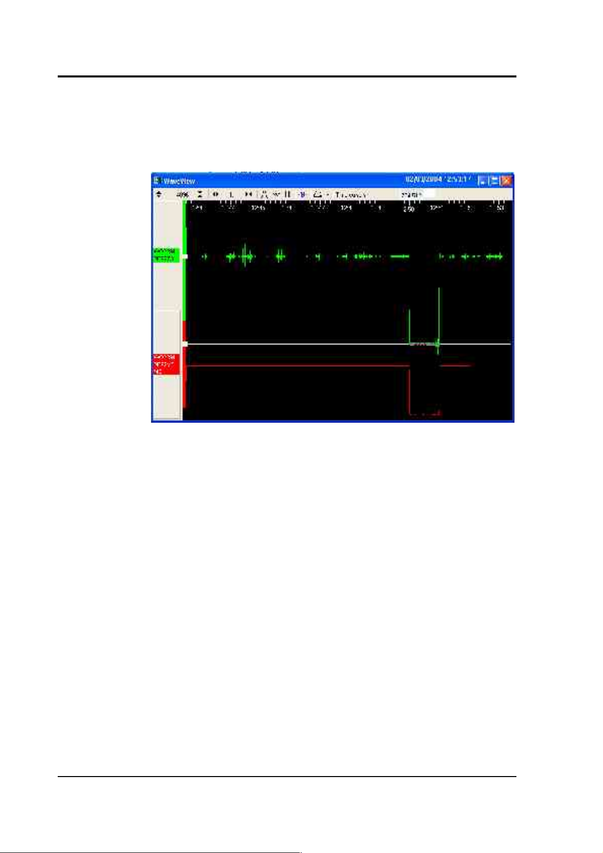
CMG-DM24S12AMS Operator's guide
7. Drag the other down to be level with the highest point. In the
following example, a step function of 1 minute duration has been
applied to the Z3 stream. Note that ground movements continue
to be observed, superimposed on the returning calibration signal.
The Ampl Cursors button will now be displaying a value, which
is the strength of the returning signal in counts (doubled, if using
a sine wave). Measure the other two signal strengths in this
manner.
Note that if you have used the Scale... option described above,
you will need to take the scale factor into account to produce the
correct number of counts. In the example, the MB (calibration
input) signal has been scaled by a factor of 40, so the signal
strength as measured by the Ampl Cursors must be divided by 40
to yield the correct value.
8. Convert to volts using the µV/Bit values given on the digitiser's
calibration sheet for the various input ports, and compare the
returned signal with the input calibration signal (MB).
9. In the example, the following data is now known:
68 Issue B
Page 69

CMG-DM24S12AMS Operator's guide
Input calibration signal
strength (MB)
9856 counts
Returning signal
strength (Z3)
704512 counts
The calibration sheets provide us with the remaining values
needed to calibrate the sensor:
Sensor acceleration response
0.254 V/m/s
2
Equivalent accel. from 1V calibration
1.968 m/s
2
Digitiser input port sensitivity 3.507212 µV/Bit
Mux channel sensitivity 255.9253 µV/Bit
From these we know that the calibration signal is producing 9856
× 247 = 2434432 µV (2.434 V). This corresponds to an equivalent
input acceleration of 2.434 × 1.968 = 4.791 m/s2.
The sensor's acceleration response is given as 0.254 V/m/s2, so
that an acceleration of 4.791 m/s2 will produce an output of 0.254
× 4.791 = 1.217 V (1216904 µV), which corresponds to a count
number at the digitiser's input port of 1216904 / 3.5 = 347687
counts.
Because the signal is transmitted differentially, the count number
observed at the digitiser should be double this: 695373 counts.
The actual signal at the digitiser of 704512 counts is within 1.5% of
this value, indicating that the sensor is adequately calibrated.
10.If you know the local value of g, you can also perform absolute
calibration by tilting the sensor by 90 ° and varying the
calibration signal until it precisely compensates for the signal
generated due to gravity.
March 2004 69
Page 70

CMG-DM24S12AMS Operator's guide
11.Calibrate ports CH3 and CH4 in the same way, but with the N/S
calibration channel selected. You must wait for the previous
calibration to finish before doing this: clicking Inject now has no
effect whilst the Calibration enable relay is open.
12.Calibrate ports CH5 and CH6 in the same way, but with the E/W
calibration channel selected.
13.Close the window and right-click on the second internal
digitiser's icon. Select Control... and open the Calibration pane.
14.Repeat steps 2 – 11 to calibrate ports CH7 – 12 in pairs: CH7 and
CH8 on the Z channel, CH9 and CH10 on the N/S channel, and
CH11 and CH12 on the E/W channel.
If you prefer, you can inject your own signals into the system at any
point (together with a Calibration enable signal, if required) to provide
independent measurements, and to check that the voltages around the
calibration loop are consistent. For reference, a DM24-series digitiser
will generate a calibration signal of around 16000 counts / 4 V when set
to 100% (sine-wave or step), and around 10000 counts / 2.5 V when set to
50%.
70 Issue B
Page 71

CMG-DM24S12AMS Operator's guide
Appendix A: Connectors and cables
Appendix A.1: DM24S12AMS connectors
Data ports
DIGITAL A − F ports
These are standard 10-pin mil-spec sockets (02E-12-10S).
Pin Function
A Power 0 V
B Power +10 – +36 V
C GPS data
D GPS 1pps signal
E RS232 receive (pin 2 internally)
F RS232 transmit (pin 3 internally)
G Data ground
H Trigger out, common
J Trigger out, normally-open
K Trigger in
The trigger lines H, J and K are referenced to 0 V at pin A, so that the
triggering system is isolated.
CH 1 – 12 ports
These are standard 10-pin mil-spec sockets (02E-12-10S).
Pin Function
A Power 0 V
B Power +12 V
D Calibration signal
March 2004 71
Page 72

CMG-DM24S12AMS Operator's guide
E Signal ground
F Calibration enable
J Data in +ve
K Data in –ve
AUXILIARY port
The port is a standard 19-pin mil-spec plug (02E-14-19P).
Pin Function
A Internal digitiser A channel 0
B Internal digitiser A channel 1
C Internal digitiser A channel 2
D Internal digitiser A channel 3
E Internal digitiser A channel 4
F Internal digitiser A channel 5
G Internal digitiser A channel 6
H Internal digitiser A channel 7
J Internal digitiser B channel 0
K Internal digitiser B channel 1
L Internal digitiser B channel 2
M Internal digitiser B channel 3
N Ground
P Internal digitiser B channel 4
R Internal digitiser B channel 5
S Internal digitiser B channel 6
T Internal digitiser B channel 7
72 Issue B
Page 73

CMG-DM24S12AMS Operator's guide
GPS port
This is a standard 10-pin mil-spec plug (02E-12-10P).
Pin Function
A Power 0 V
B Power +12 V
C 1Hz reference (RS232 level isolated)
G Data ground
J Data transmit
K Data receive
Power ports
BATTERY / UPS connector
This is a standard 10-pin mil-spec plug (02E-12-10P).
Pin Function
A 0V
B Battery +ve
C Charge output
If pins B and C are connected to each other, an attached rechargeable
battery will be trickle-charged whenever there is enough additional
power from the mains or DC POWER socket. If mains power is used, the
battery will never draw more than 1 A of current for charging.
DC POWER connector
This is a standard 10-pin mil-spec plug (02E-12-10P).
Pin Function
A 0V
B Battery +ve
March 2004 73
Page 74

CMG-DM24S12AMS Operator's guide
PC ports
The remaining connectors are wired directly to the DM24S12PC's builtin laptop PC.
USB connector
This is a standard 6-pin mil-spec socket (02E-10-06S).
Pin Function
A +5 V DC (USB Type A pin 1)
B Data +ve (USB Type A pin 3)
C Data –ve (USB Type A pin 2)
D 0 V (USB Type A pin 4)
E Shielding
NETWORK connector
This is a standard 6-pin mil-spec plug (02E-10-06P).
Pin Function
B Data transmit +ve (pin 1)
C Data receive +ve (pin 3)
E Data transmit –ve (pin 2)
F Data transmit –ve (pin 6)
TELEPHONE connector
This is a standard 6-pin mil-spec socket (02E-10-06S).
Pin Function
E Data receive (pin 3)
F Data transmit (pin 4)
74 Issue B
Page 75

CMG-DM24S12AMS Operator's guide
Appendix A.2: 5U connectors
The 5U sensor has a single 10-pin mil-spec connector (02E-12-10P) for
both power and acceleration transmission.
Pin Function
A Power 0 V
B Power +12 V
C High gain acceleration +ve
D Calibration signal
E Signal ground
F Calibration enable
G High gain acceleration –ve
H Motor control
J Low gain acceleration +ve
K Low gain acceleration –ve
March 2004 75
Page 76
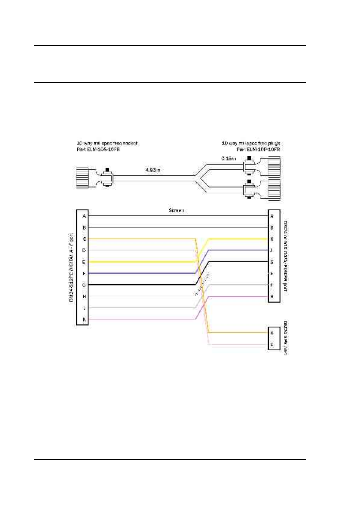
CMG-DM24S12AMS Operator's guide
Appendix A.3: Cable from DM24 or 5TD DATA/POWER and
GPS to DM24S12AMS DIGITAL A − F
76 Issue B
Page 77
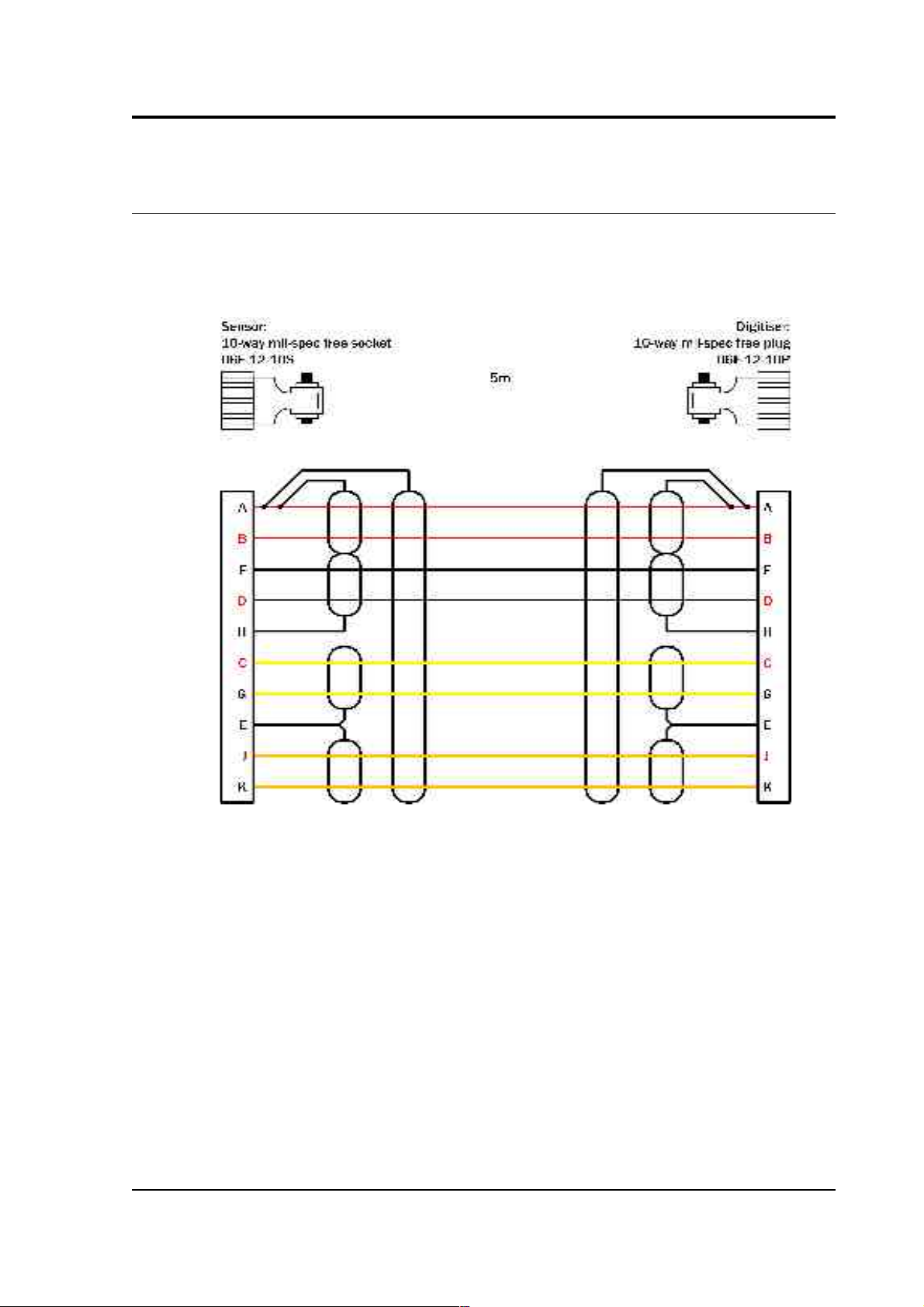
CMG-DM24S12AMS Operator's guide
Appendix A.4: Cable from 5U sensor to DM24S12 series
CH 1 – 12
March 2004 77
Page 78

CMG-DM24S12AMS Operator's guide
Appendix B: Specifications
Output Low gain output options
2g, 1g, 0.5g, 0.1g
Corresponding high gain
outputs
0.2g, 0.1g, 0.05g, 0.01g
Dynamic range at 2 g standard
Dynamic range, 0.005 – 0.05
Hz
< 140 dB
Dynamic range, 3 – 30 Hz < 127 dB
Standard frequency band
DC – 100 Hz (–3dB
point)
Optional low-pass corner 50, 100 or 200 Hz
Linearity 0.1 % of full scale
Cross-axis rejection
0.001g / g
Calibration
controls
Open-loop response pin on connector
Closed-loop response pin on connector
Step function response
may be added to openand closed-loop
calibrations
External inputs
Sine-wave, step, or
pseudo-random
Physical Lowest spurious resonance 450 Hz
Operating temperature
range
–20 to +70 °C
Pressure jacket material
hard anodised
aluminium
Power / signal connector
Mil-spec connector on
sensor housing (02E14-19P)
Dimensions 75 × 75 × 125 mm
Weight 908 g
Power Current at 12 V DC 8 mA
78 Issue B
Page 79

CMG-DM24S12AMS Operator's guide
March 2004 79
 Loading...