

Page 1

CMG-DM24
Mk3 Digitizer
Ope rato r's guide
Part No. MAN-D24-0004
Designed and manufactured by
Güralp Systems Limited
3 Midas House, Calleva Park
Aldermaston RG7 8EA
England
Proprietary Notice: The information in this manual is
proprietary to Güralp Systems Limited and may not be
copied or distributed outside the approved recipient's
organisation without the approval of Güralp Systems
Limited. Güralp Systems Limited shall not be liable for
technical or editorial errors or omissions made herein,
nor for incidental or consequential damages resulting
from the furnishing, performance, or usage of this
material.
Issue N 2009-10-05
Page 2

CMG-DM24
Table of Contents
1 Introduction...............................................................................................................4
1.1 Features...............................................................................................................4
2 Installing the CMG-DM24.........................................................................................6
2.1 Power supplies....................................................................................................6
2.2 Connecting sensors.............................................................................................6
2.3 Connecting external hardware...........................................................................7
2.4 The DM24BH borehole digitizer........................................................................9
3 Using the DM24.......................................................................................................11
3.1 Taps...................................................................................................................11
3.2 Streams.............................................................................................................13
3.3 Transmission modes.........................................................................................15
3.4 Downloading stored data..................................................................................19
3.5 Reading DM24 disks.........................................................................................20
3.6 DM24 USB Host Operations.............................................................................24
4 Using Scream!..........................................................................................................29
4.1 Configuring digitizers.......................................................................................29
4.2 Controlling digitizers........................................................................................44
5 Command line interface..........................................................................................51
5.1 Introduction......................................................................................................51
5.2 Getting help......................................................................................................52
5.3 General configuration.......................................................................................53
5.4 Port configuration.............................................................................................57
5.5 Output configuration........................................................................................61
5.6 Triggering..........................................................................................................66
5.7 Calibration........................................................................................................71
5.8 Actions..............................................................................................................74
5.9 Data storage and transmission.........................................................................77
5.10 Downloading over the serial port...................................................................83
5.11 Downloading over FireWire...........................................................................87
6 Inside the DM24......................................................................................................89
6.1 State of health information..............................................................................89
2 Issue N
Page 3

Operator's guide
6.2 Updating firmware with Scream!.....................................................................94
6.3 Setting up external triggering ..........................................................................97
6.4 Technical details............................................................................................102
7 Güralp Compressed Format..................................................................................105
7.1 GCF blocks......................................................................................................105
7.2 Sending GCF streams over a network............................................................108
7.3 Sending GCF streams over a serial link.........................................................110
8 Connector pinouts.................................................................................................113
8.1 SENSOR A and B ports...................................................................................113
8.2 AUXILIARY port.............................................................................................114
8.3 GPS Port..........................................................................................................115
8.4 DATA IN port..................................................................................................116
8.5 FIREWIRE port................................................................................................117
8.6 USB port..........................................................................................................118
8.7 DATA OUT port..............................................................................................119
9 Digitizer specifications..........................................................................................120
10 Revision history...................................................................................................122
October 2009 3
Page 4
CMG-DM24
1 Introduction
The Güralp CMG-DM24 multi-channel digitizer is a state-of-the-art
digital module for seismic data. It can be supplied in several different
formats:
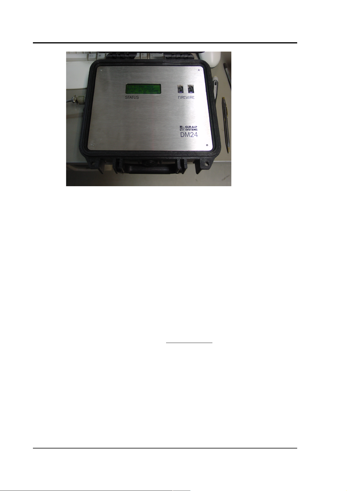
A stand-alone DM24 (below) can be installed with existing or new
analogue sensors. Conversely, a modular digitizer is fixed to, and
becomes a physical part of, a Güralp seismometer. These can be
supplied with new instruments, or retrofitted to CMG-1T, 3T, 3ESP or
40T seismometers at the factory. A modular digitizer benefits from the
sensor's isolated, clean and stable environment and allows it to operate
at optimum noise levels and precision
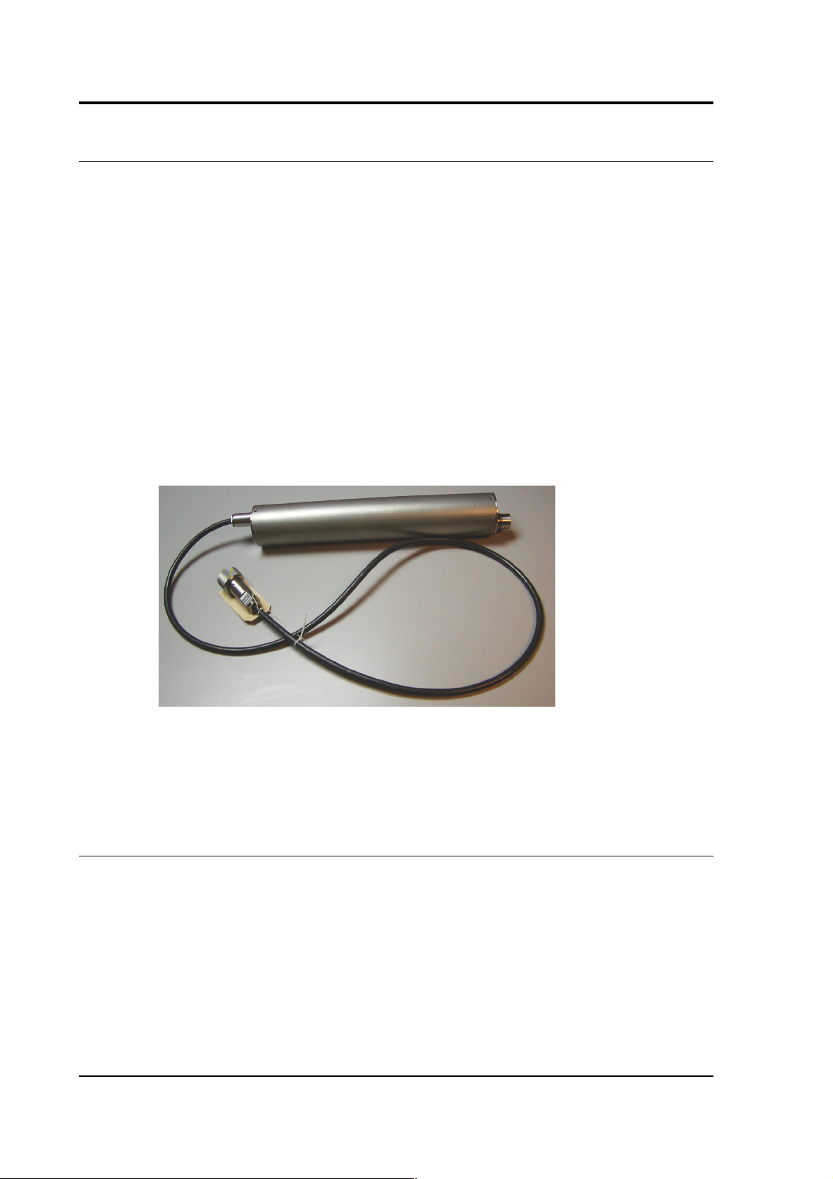
The DM24 can also be supplied in borehole sonde form, with optional
strain relief accessories. All these units operate identically, although
the connector for the borehole unit is necessarily more compact.
A DM24 is especially powerful when operated in conjunction with a
Güralp data module such as the CMG-DCM or AM. All three types sensor, digitizer, and data module - can be customized to meet your
installation requirements.
1.1 Features
• A built-in Digital Signal Processor (DSP), which can provide
simultaneous multiple sample rate data streams at user
selectable rates. Up to 6 streams of data for each component are
available at sample rates from 1 to 1000 samples/s.
• A precision microprocessor-controlled time-base synchronizes
the Analogue-to-Digital Converters and the DSP, as well as
providing time-stamps for data blocks.
4 Issue N
Page 5

Operator's guide
• Time synchronization to an attached GPS receiver or from a
remote time source.
• An ARM microprocessor, which formats and buffers data in an
on-board 256k RAM ring buffer.
• Efficient data storage and transmission using the Güralp
Compressed Format (GCF).
• RS232 serial data output at user-selectable baud rates, with
automatic modem dial-out facility.
• Built-in microprocessor system configuration and sensor
control, including locking and unlocking, centring and
calibration.
• Low system power consumption.
• Flash EEPROM for program code and filter coefficients.
• High-impedance, low-noise, differential input pre-amplifier
modules with adjustable gain.
• Internal electronic thermometer provides temperature
measurements at an accuracy up to ± 0.33 °C, with a linearity of
± 0.5 °C.
• Optional Flash memory storage.
• Optional IEEE 1394 FireWire interface, allowing you to
download GCF data directly onto a compatible disk by simply
plugging the disk into the FireWire connector inside the casing,
and monitoring progress on the built-in LCD screen.
• Optional USB interface, enabling fast data transfer direct to a PC
or other recording device.
The DM24 can be connected to two Güralp analogue sensors, or up to
six conventional single-axis seismometers, through its SENSOR A and
SENSOR B connectors. (Single-sensor and integrated DM24 units have
only SENSOR A connectors). Signals from these sensors are digitized to
32-bit precision, initially at 2000 Hz. Data is output through the DATA
OUT serial port of the digitizer in the flexible GCF format, either to a
PC or a Güralp data module. Timing signals are gathered from a GPS
unit connected to the single GPS port.
October 2009 5
Page 6

CMG-DM24
2 Installing the CMG-DM24
2.1 Power supplies
The DM24 accepts power from lines in its DATA OUT port. This is a
Güralp standard 10-pin combined serial/power interface, a cable for
which can be obtained from Güralp Systems. A standard 12V DC
power supply is recommended.
2.2 Connecting sensors
The DM24 is configured for use with Güralp Systems feedback
sensors, which can be connected directly to the SENSOR A and
SENSOR B ports. No further configuration of the sensor is necessary;
the input ports carry sensor power, four channels of differential
velocity, mass position and calibration signals. The AUXILIARY port
allows you to measure and digitize environmental parameters, e.g.
local temperature, pressure, or signals from other scientific
instruments.
In addition, two pins on the AUXILIARY port allow you to input signals
for a fourth, full-rate 24-bit data channel. This channel is digitized
continuously, but is interrupted when you calibrate the instrument, so
that the DM24 can return the calibration signal on a stream with a
different name. When calibration is over, the fourth channel returns to
digitizing the external source.
If you prefer, you can attach any seismometer with balanced
differential output to the signal inputs of the DM24. You will need to
make up a cable to connect the relevant pins of the SENSOR A or B
port to your instrument(s). See Section 8.1, page 113, for details of the
connector used.
If you have only one sensor, you should attach it to the SENSOR A
port, since only this port can be used to send control signals to it (e.g.
mass locking and unlocking). The SENSOR B port can therefore only
be used for sensors which do not require remote control signals, such
as Güralp accelerometers or the CMG-6 series of medium noise
instruments. The 4-channel model of the DM24 does not have a
SENSOR B port.
6 Issue N
Page 7
Operator's guide
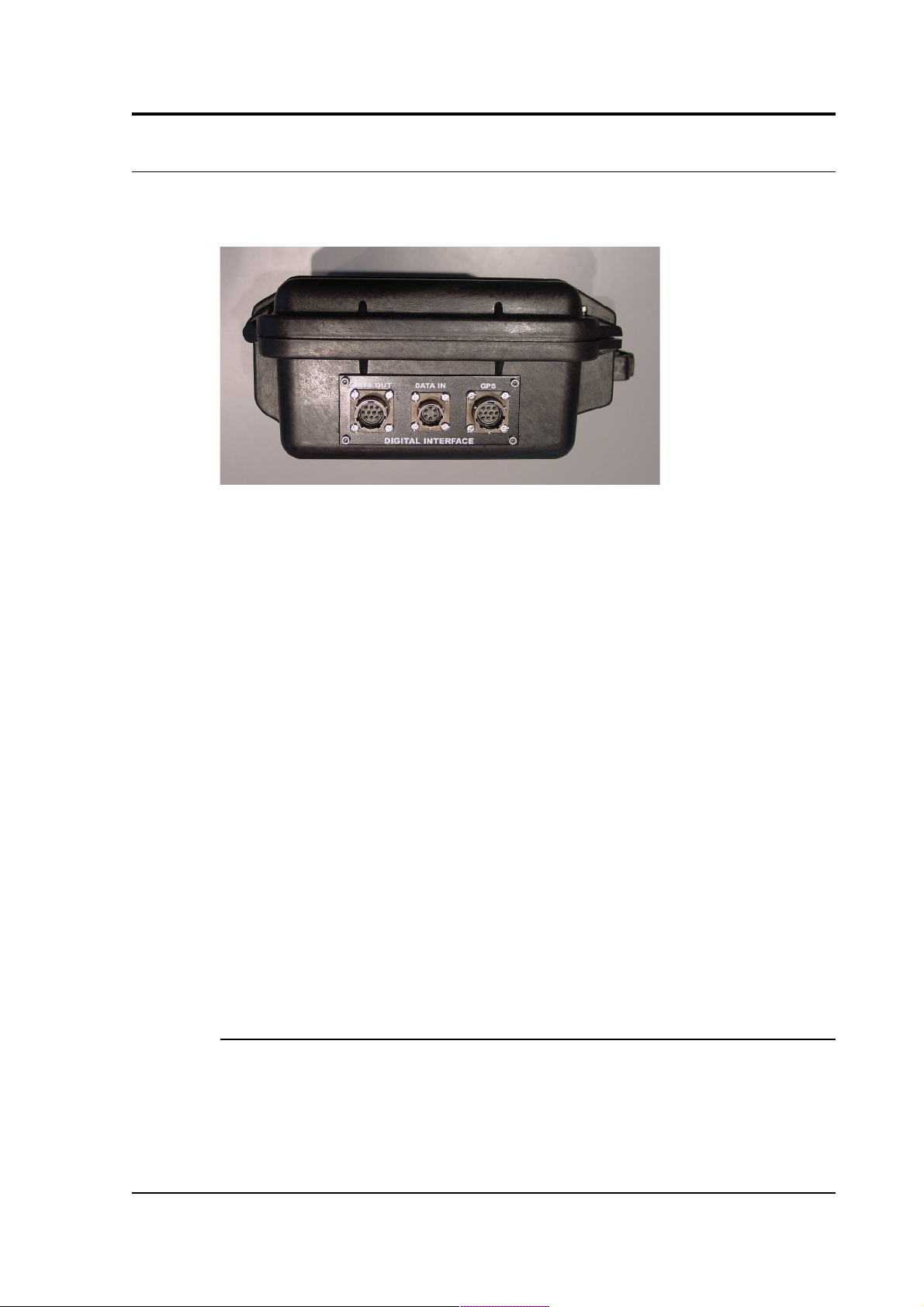
2.3 Connecting external hardware
On a stand-alone DM24, the digital ports are located on the opposite
side to the analogue ports:
The DM24 outputs data through its DATA OUT port. This is a
standard RS232 serial link, outputting data in GCF format according to
the particular configuration of the instrument. The DM24 has a default
baud rate of 38,400. You can change this later using the BAUD
command or from Güralp Systems' control, acquisition and monitoring
software package, Scream! (see chapter 4).
A GPS connector is also provided on the front panel for attaching to a
GPS receiver. GPS signals are sent to both digitizers simultaneously,
but only the one to which it is directly attached can control the GPS
system.
The DATA IN port can be used to access the digitizer's console over a
direct serial link, or for inputting additional data streams for
transmission in GCF format.
Finally, the DM24 can be supplied with an optional USB client
interface for connecting to a PC. When this is present, the USB port
acts as a direct replacement for the DATA OUT or console port, and
appears as an additional serial port to your computer. You can
configure which port is replaced from the digitizer console (see
chapter 5).
FireWire disks
The optional IEEE.1394 (“FireWire”) ports on the DM24 may be used
to download data onto a compatible hard disk. The unit can be
supplied either with standard FireWire connectors or with robust milspec plugs (see Section 8.5, page 117, for pinout details).
October 2009 7
Page 8
CMG-DM24
Before you can use the disk, you will need to reset it. The DM24 saves
data on the hard disk in a special format, so you cannot use your PC's
operating system to reset the disk.
You can use the DM24 itself, Scream!, or gcfxtract software to reset
the disk. For instructions on using Scream! and gcfxtract, please
see the documentation for these software packages, or their on-line
help.
To reset a FireWire disk with the DM24:
1. Power up the DM24, and connect it to your computer's serial
port.
2. Open its terminal console. To do this using Güralp Systems'
Scream! software, right-click on the digitizer's icon (once it
appears) and select Terminal.... From a Güralp DCM, issue the
command minicom -n port-number.
3. Issue the command DISKMENU. You will see the message
Plug in FireWire cable
4. Plug in your disk. The DM24 will output (on the console)
information about the disk as soon as it is detected.
5. Within the next 7 seconds, press any key to bring up the disk
menu.
8 Issue N
Page 9
Operator's guide
6. Press R to reset the disk.
7. When the reset is complete, remove the disk.
You will now be able to download data onto the disk when required.
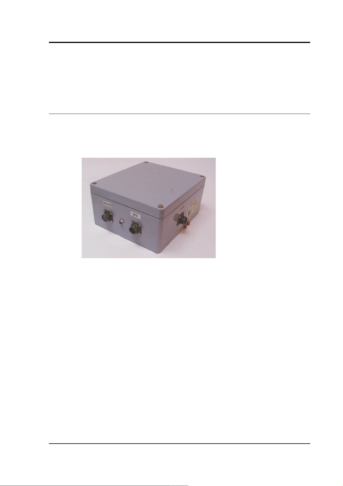
2.4 The DM24BH borehole digitizer
When the DM24 is ordered in borehole form, it is supplied with a
surface interface unit for installation at the top of the borehole. This
unit takes the single data cable from the downhole digitizer and
provides standard connections for other equipment.
The connectors provided are:
• a SENSOR connector - a 10-way mil-spec socket carrying serial
data, GPS and power to the sensor;
• a GPS connector for attaching to your GPS receiver; and
• a POWER / HOLELOCK connector which can either be connected
to a source of 12 – 30 V power for supplying to the borehole
instrumentation (including sensors), or to a Holelock Control
Unit for driving the sensor's hole lock motors. It is not usual to
power the sensor and hole lock simultaneously; once the hole
lock is engaged, you should remove the Holelock Control Unit
and cabling so that the sensor cannot be removed.
• On the reverse side, a standard 9-pin RS232 connector is
provided for connecting to a PC running Scream! using a
straight-through serial cable.
October 2009 9
Page 10

CMG-DM24
• There is also a three-pin mains (outlet) plug, which can power
the downhole instrumentation from 110 – 250 V AC as required.
10 Issue N
Page 11

Operator's guide
3 Using the DM24
Once the DM24 is connected to your equipment, it will start producing
data immediately. You can now start configuring it for your own
needs. There are two ways you can do this:
• using the graphical interface provided by Scream!, or
• over a terminal connection (see Chapter 5, page 51).
Both methods provide full access to the configuration options of the
digitizer.
In most circumstances, you will use Scream! to operate the system. For
complete information on how to use Scream! to configure and control
your instrument, please refer to the Scream! user guide.
3.1 Taps
The DM24 converts analogue signals to digital data at a high sample
rate, which is then reduced in steps. This process is known as
decimation, and each output stage is called a tap.
The highest data rate you can choose is 1000 samples/s. This rate can
only be produced by Tap 0, the first tap. Tap 0 can also produce data
at 500, 400, 200 or 100 samples/s.
After Tap 0 there are three more taps. Each tap produces data at an
integer sample rate, which must be 2, 4, 5, 8 or 10 times lower than the
previous tap.
For example, the following is a possible sequence:
Tap 0 : 500 samples/s
Tap 1 : 50 samples/s (divide by 10)
Tap 2 : 10 samples/s (divide by 5)
Tap 3 : 5 samples/s (divide by 2)
The digitizer always generates all four sample rates, but it does not
have to output them. You can configure any set of taps to output. You
can also have different taps configured for different sensor
components.
October 2009 11
Page 12

CMG-DM24
All of these configuration options are easily changed via Scream!, or
you can use the terminal commands SET-TAPS and CONTINUOUS.
Triggering
The DM24 has a flexible triggering system. When the digitizer triggers,
it can optionally output (or store – see DUAL mode on page 16)
additional data. Any combination of tap and component can be output
as the result of a trigger.
In the example above, you might configure the sensor to output Tap 2
data (at 10 samples/s) continuously, but when a trigger is declared, to
output Tap 0 data (at 500 samples/s) as well.
Using triggering helps you to use limited storage capacity or
bandwidth more effectively.
The digitizer can look at the data from any tap to decide if a trigger has
occurred, including taps which it does not output. Which tap you
choose depends on the frequencies you want the trigger system to be
most sensitive to.
There are three types of trigger.
• A LEVEL trigger occurs when the absolute sample values exceed
a configured value.
The commands GTRIGGERS, MICROG, and HIGHPASS control
LEVEL triggering.
• An STA/LTA trigger occurs when the ratio of a short-term
average to a long-term average for recent data exceeds a
configured value.
The commands TRIGGERS, TRIGGERED, STA, LTA, RATIOS, and
BANDPASS control STA/LTA triggering.
• A software trigger occurs when you issue the command
S/WTRIGGER.
The DM24 can output data streams for a period of time before the
trigger starts, and after the trigger ends. The commands PRE-TRIG and
POST-TRIG set these time periods.
Triggering options can also be configured through Scream!.
12 Issue N
Page 13

Operator's guide
3.2 Streams
The DM24 organizes the data it produces into streams. Each stream
has a 6-character identifier. The first four characters are taken from the
System ID of the digitizer. When you receive the instrument, the
System ID is set to its serial number, but you can change it in Scream!
or with a terminal command.
The next character denotes the component or output type:
• Z, N, and E denote the vertical, north/south, and east/west
components respectively.
• X denotes the fourth full-rate data channel, which is provided
for connection to your own monitoring equipment via the
AUXILIARY connector (if present).
• C denotes the calibration input channel, which replaces the X
streams whilst calibration is in progress.
• M denotes one of the 16 slow-rate Mux (multiplex) channels.
Three of these (M8, M9 and MA) are used to report the sensor
mass positions. Channels MC and MD are connected to the X and
Y axes of the downhole inclinometer.
• For Z, N, E, X, and C streams, the last character represents the
output tap. Taps correspond to stages in the decimation process
within the digitizer, allowing the DM24 to output several
different data rates simultaneously. There are four taps,
numbered 0 to 3; 0 has the highest data rate and 3 the lowest.
Data streams end in 0, 2, 4 and 6 for taps 0, 1, 2 and 3
respectively.
If you configure the DM24 to output triggered data, this will
appear in separate streams ending with the letters G, I, K or M
for taps 0, 1, 2 and 3 respectively.
The DM24 also generates a stream ending 00. This is a status stream
containing useful diagnostic information, in plain text form (see
Section 6.1, page 89).
Digitizers for multiple instruments
The standard DM24 has 4 full-rate channels: one per component of a
triaxial instrument, plus the auxiliary and calibration channel.
October 2009 13
Page 14

CMG-DM24
Some DM24 modules, known as “6-channel digitizers”, are designed
for use with two instruments simultaneously, connected to the ports
SENSOR A and SENSOR B. These digitizers actually have 7 full rate
data channels, including the auxiliary/calibration channel. When you
enable calibration on these digitizers, the signal is passed to both
instruments. All 7 channels share the same settings for the four output
taps.
A 6-channel digitizer will output full-rate streams with the following
final characters:
Z/N/E0
SENSOR A at tap 0
Z/N/E1
SENSOR B at tap 0
Z/N/E2
SENSOR A at tap 1
Z/N/E3
SENSOR B at tap 1
Z/N/E4
SENSOR A at tap 2
Z/N/E5
SENSOR B at tap 2
Z/N/E6
SENSOR A at tap 3
Z/N/E7
SENSOR B at tap 3
Z/N/EG
SENSOR A at tap 0,
triggered
Z/N/EH
SENSOR B at tap 0,
triggered
Z/N/EI
SENSOR A at tap 1,
triggered
Z/N/EJ
SENSOR B at tap 1,
triggered
Z/N/EK
SENSOR A at tap 2,
triggered
Z/N/EL
SENSOR B at tap 2,
triggered
Z/N/EM
SENSOR A at tap 3,
triggered
Z/N/EN
SENSOR B at tap 3,
triggered
X/C0
Auxiliary at tap 0
X/C1
Auxiliary at tap 1
X/C2
Auxiliary at tap 2
X/C3
Auxiliary at tap 3
Standard 6-channel digitizers have the same 8 Mux channels as their
3-channel counterparts: M8, M9 and MA for the mass positions of
SENSOR A, and MB to MF for your own equipment. These digitizers are
designed for use with a strong-motion instrument or geophone
attached to SENSOR B, and so do not expose the mass positions for
this sensor. In addition, SENSOR B cannot be locked, unlocked, or
centred.
Optionally, a digitizer can be supplied which provides 5 additional
Mux channels M3 to M7 for external equipment (again exposed on the
AUXILIARY connector). 6-channel DM24 modules with this option also
measure the mass positions of SENSOR B, if available, and output
these on streams ending M0, 1 and 2.
14 Issue N
Page 15
Operator's guide
3.3 Transmission modes
Transmission modes are an important concept on the DM24. The
current transmission mode determines whether the unit stores data in
its on-board Flash memory, sends it over the serial link in GCF format
or does some combination of these.
You can switch between transmission modes with a console command
(see chapter 5, page 51) or by using the Scream! configuration
interface.
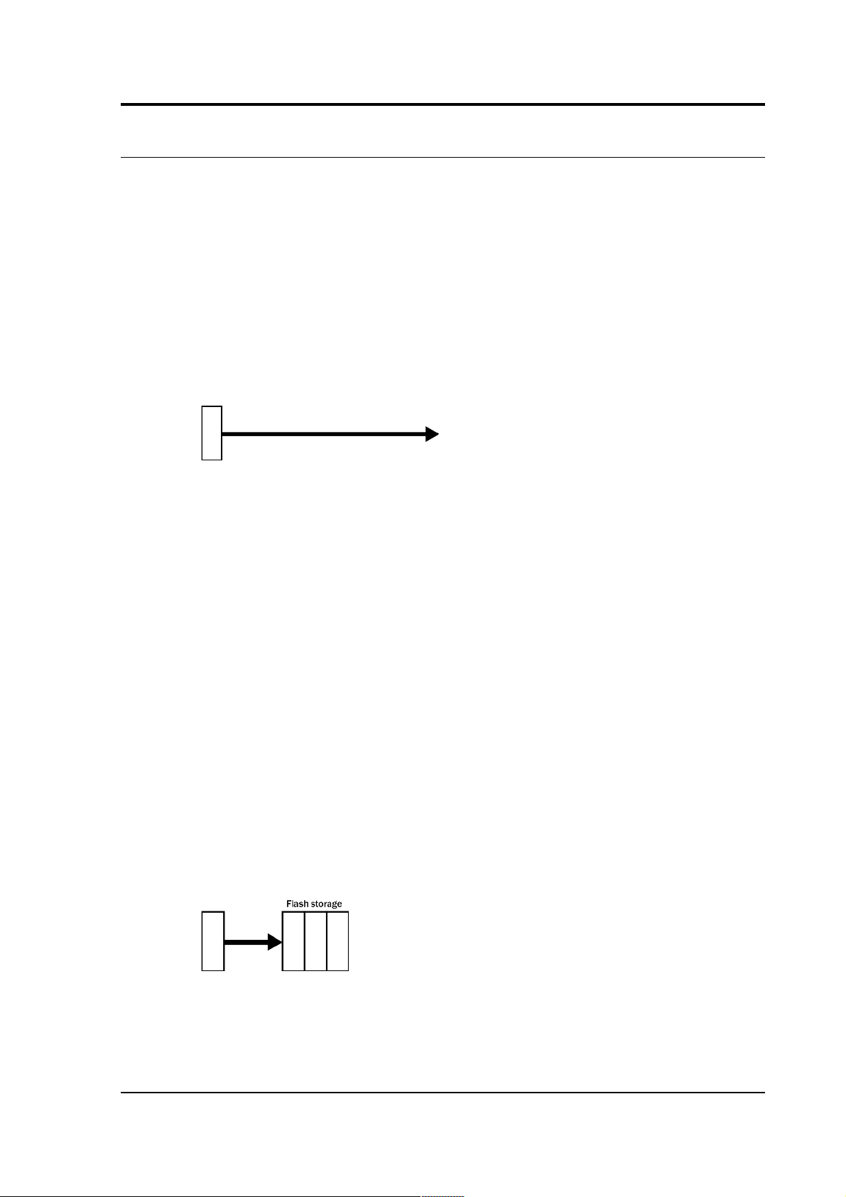
DIRECT
Command: DIRECT
Instructs the DM24 not to use Flash memory for storage. Instead, all
data is transmitted directly to clients. An instrument in DIRECT mode
still honours the GCF Block Recovery Protocol: a temporary RAM
buffer always holds the last 256 blocks generated and, if a client fails
to receive a block, it can request its retransmission.
If you expect breaks in communication between the instrument and its
client to last more than 256 blocks, or if you want the instrument to
handle breaks in transmission (rather than relying on the client to
request missed blocks), you should use
• ADAPTIVE mode, if you want data to stay as near to real time as
possible (but do not mind if blocks are received out of order) or
• FIFO mode, if you need blocks to be received in strict order (but
do not mind if the instrument takes a while to catch up to real
time).
FILING
Command: FILING
Instructs the DM24 not to transmit blocks to clients automatically, but
to store all digitized data in the Flash memory. If you have chosen the
RECYCLE buffering mode (see below), the memory is used in circular
fashion, i.e. if it becomes full, incoming blocks begin overwriting the
October 2009 15
Page 16
CMG-DM24
oldest in memory. If, instead, the WRITE-ONCE buffering mode is
active, the instrument will switch to DIRECT mode (see above) when
the memory becomes full.
You can retrieve blocks from an instrument in FILING mode by
connecting to its terminal interface and issuing commands such as
FLUSH, or through Scream! (see below).
Heartbeat messages
When in FILING mode, an instrument transmits “heartbeat” messages
over its data port. These short messages take the place of data blocks,
and ensure that programs such as Scream! know that an instrument is
present.
You can change the frequency of heartbeat messages from Scream!'s
Control window, or with the command HEARTBEAT.
DUPLICATE
Command: DUPLICATE
Instructs the DM24 to transmit streams directly to clients as for
DIRECT mode, but also to store all data into Flash storage as for
FILING mode.
If a client fails to acknowledge a block, the digitizer does not attempt
to retransmit it.
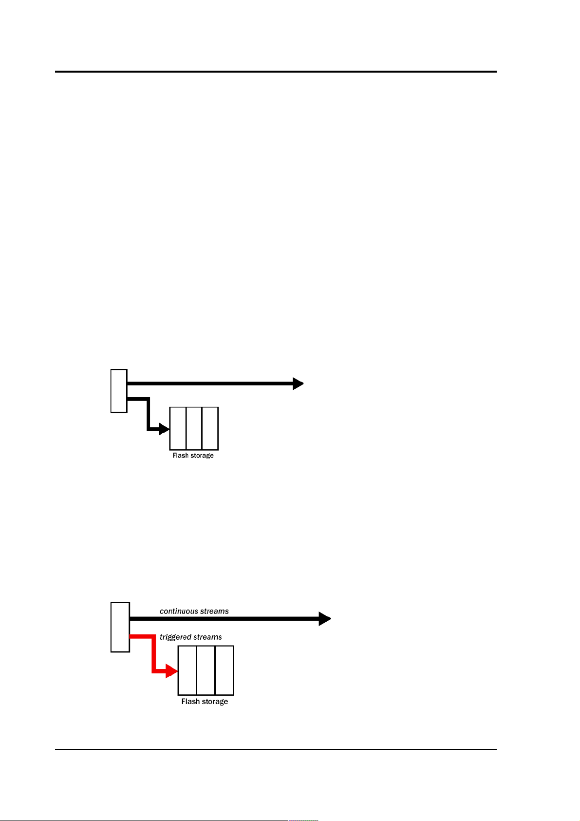
DUAL
Command: DUAL
16 Issue N
Page 17
Operator's guide
Instructs the DM24 to transmit any continuous streams directly to
clients as for DIRECT mode, but to store triggered data into Flash
storage as for FILING mode.
If you choose DUAL mode but do not select any continuous streams for
output, the instrument will send heartbeat messages as for FILING
mode. Scream! can pick these up and download new data as
necessary.
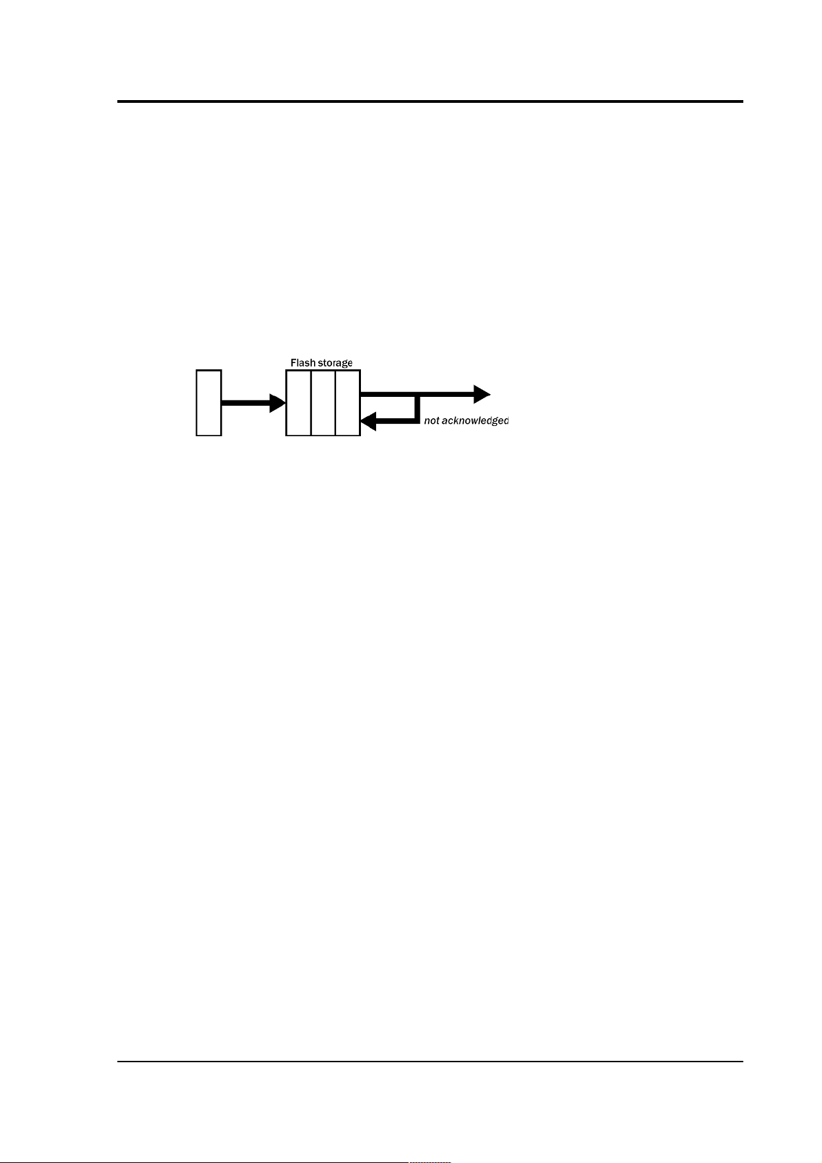
FIFO (First In First Out)
Command: FIFO
Instructs the DM24 to begin writing blocks to Flash memory as for
FILING mode, but also to transmit data to clients. Data is transmitted
in strict order, oldest first; the DM24 will only transmit the next block
when it receives an explicit acknowledgement of the previous block.
If the communications link is only marginally faster than the data rate,
it will take some time to catch up with the real-time data after an
outage. If you want data to be transmitted in real-time where possible,
but are worried about possible breaks in communication, you should
use ADAPTIVE mode instead.
FIFO mode will consider a data block successfully transmitted once it
has received an acknowledgement from the next device in the chain. If
there are several devices between you and the instrument, you will
need to set up the mode for each device (if applicable) to ensure that
data flow works the way you expect.
Like all the transmission modes, FIFO mode does not delete data once
it has been transmitted. You can still request anything in the Flash
memory using Scream! or over the command line. The only way data
can be deleted is if it is overwritten (in the RECYCLE buffering mode,
see below) or if you delete it manually.
ADAPTIVE
Command: ADAPTIVE
October 2009 17
Page 18
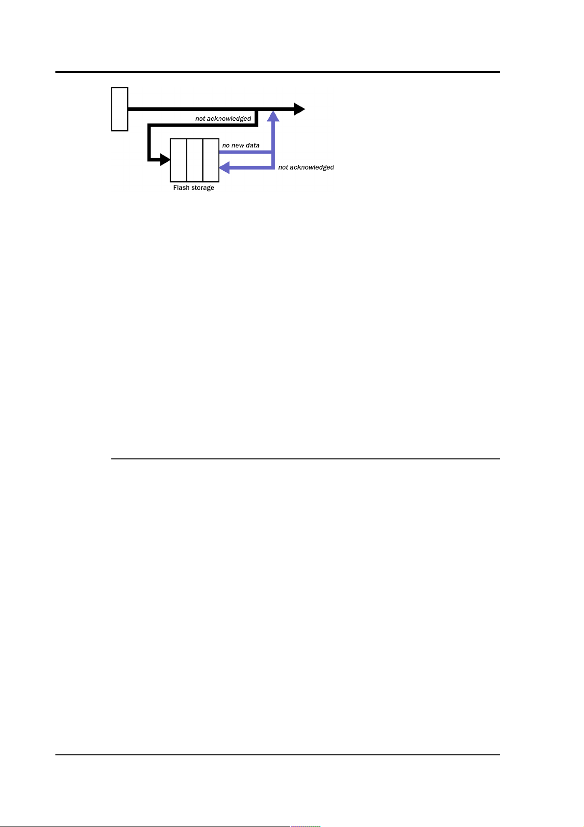
CMG-DM24
Instructs the DM24 to transmit current blocks to clients if possible, but
to store all unacknowledged blocks in the Flash memory and re-send
them, oldest first, when time allows. ADAPTIVE mode is best suited for
“real-time” installations where the link between digitizer and client is
intermittent or difficult of access.
If the communications link is only marginally faster than the data rate,
it will usually be busy transmitting real-time data. Thus, it may take a
while for the instrument to work through the missed blocks. In this
case, and if your client supports it, you may prefer to use the Block
Recovery Protocol to request missed blocks where possible (see
section 7.3, page 110).
Some software packages (most commonly Earthworm) cannot handle
blocks being received out of time order. If you are using such a
package, ADAPTIVE mode will not work and may crash the software.
Buffering modes
There are two different buffering modes which affect how the internal
flash memory is utilized. Either may be used with any of the available
transmission modes.
RE-USE / RECYCLE
Command: RE-USE
Instructs the DM24 to carry on using the current transmission mode
when the Flash memory becomes full, overwriting the oldest data
held. This buffering mode is called RECYCLE in Scream! and on the
DCM.
For example, in DUAL mode with RECYCLE buffering, the latest
continuous data will be transmitted to you as normal, and the latest
triggered data may be retrieved from the Flash memory using Scream!
or the command line. However, if you do not download data regularly
from the Flash memory, you may lose older blocks. This mode thus
lets you define the end point of the data held by the instrument.
18 Issue N
Page 19

Operator's guide
WRITE-ONCE
Command: WRITE-ONCE
Instructs the DM24 to stop writing data to the Flash memory when it is
full, and to switch to DIRECT mode automatically.
For example, in FIFO mode with WRITE-ONCE buffering, the station
will transmit data to you continuously, but also save it in the Flash
memory until it is full. Once full, the instrument will switch to
DIRECT mode and continue transmitting, though no further data will
be saved. This mode thus lets you define the start point of the data
held by the instrument.
3.4 Downloading stored data
If you choose a transmission mode where data is stored in Flash
memory, you will need to recover this data at a later date. You can do
this either over the serial link or using the DM24's FireWire interface.
Downloading over FireWire
To download data over FireWire, plug the disk in and issue the
command DISKMENU from the digitizer's console. The digitizer will
reply with a list of download options.
If you have not used the disk before, you will need to reset it. Resetting
the disk prepares it for the DM24 to use and sets up the DFD filing
system (see below). Press R then ENTER to reset the disk. When the
DM24 is ready, it will return to the menu.
You can also use gcfxtract or Scream! to prepare a FireWire disk.
To download all the new data held by the DM24, press N then ENTER,
or wait for 10 seconds. The DM24 will transfer any data it has
recorded since the last download and then mark this data as
transferred.
You can also download selections of data (including the entire
contents of the data store, if desired) with the DISKMENU command.
See Section 5.9, page 77, for more information.
The DM24 checks for a FireWire disk when it boots up. If there is
enough new data waiting to be transferred (by default 128 Mb), the
DM24 will automatically transfer it onto the disk. The digitizer then
updates its internal pointers to mark this data as already downloaded.
October 2009 19
Page 20

CMG-DM24
This feature is particularly useful for autonomous installations: after
the digitizer has been retrieved from a field experiment, simply
powering it up with a prepared disk attached will make it transfer all
the data it has recorded during the experiment.
While the FireWire interface is active, it will consume about 200 mA
of power (from a 12 Volt supply). If you interrupt a transfer whilst it is
in progress, the digitizer will re-boot and will not mark data as
downloaded. Because of this, the next time you transfer data, some
will be duplicated. You will not, however, lose any data.
Downloading over the serial link
To download data over the serial link:
1. Open the digitizer's console. To do this using Güralp Systems'
Scream! software, right-click on the digitizer's icon (once it
appears) and select Terminal.... From a Güralp DCM, issue the
command minicom -n port-number.
2. If you want to download all data held in the Flash memory,
issue the command
ALL-FLASH ALL-DATA DOWNLOAD
3. Alternatively, select a particular set of streams, sample rates and
times to download using the STREAM, S/S, FROM-TIME and TO-
TIME commands, and finish with DOWNLOAD. See Section 5.9,
page 77, for more details.
4. Issue the GO command to start transferring data. If you are
using Scream! or a DCM, closing the terminal session will have
the same effect.
3.5 Reading DM24 disks
When the DM24 saves data onto a FireWire disk, it uses a special
format called DFD.
You can read this data into a PC using Scream! or the gcfxtract
utility, which is freely available from the Güralp Systems Web site.
Linux and Solaris command line utilities are also available for reading
data from a DFD disk.
The DFD format is not the same as that used by the Güralp Systems
DCM data module, which uses a FAT32-compatible journalling file
system.
20 Issue N
Page 21
Operator's guide
Güralp Systems can provide fully-tested, formatted disks with
FireWire and USB connectors. Alternatively, a third-party FireWire
disk may be used (although compatibility is not guaranteed).
To read a disk using gcfxtract:
1. Attach the disk to your computer. You can use FireWire,
USB, or any other interface supported by your computer and
the disk.
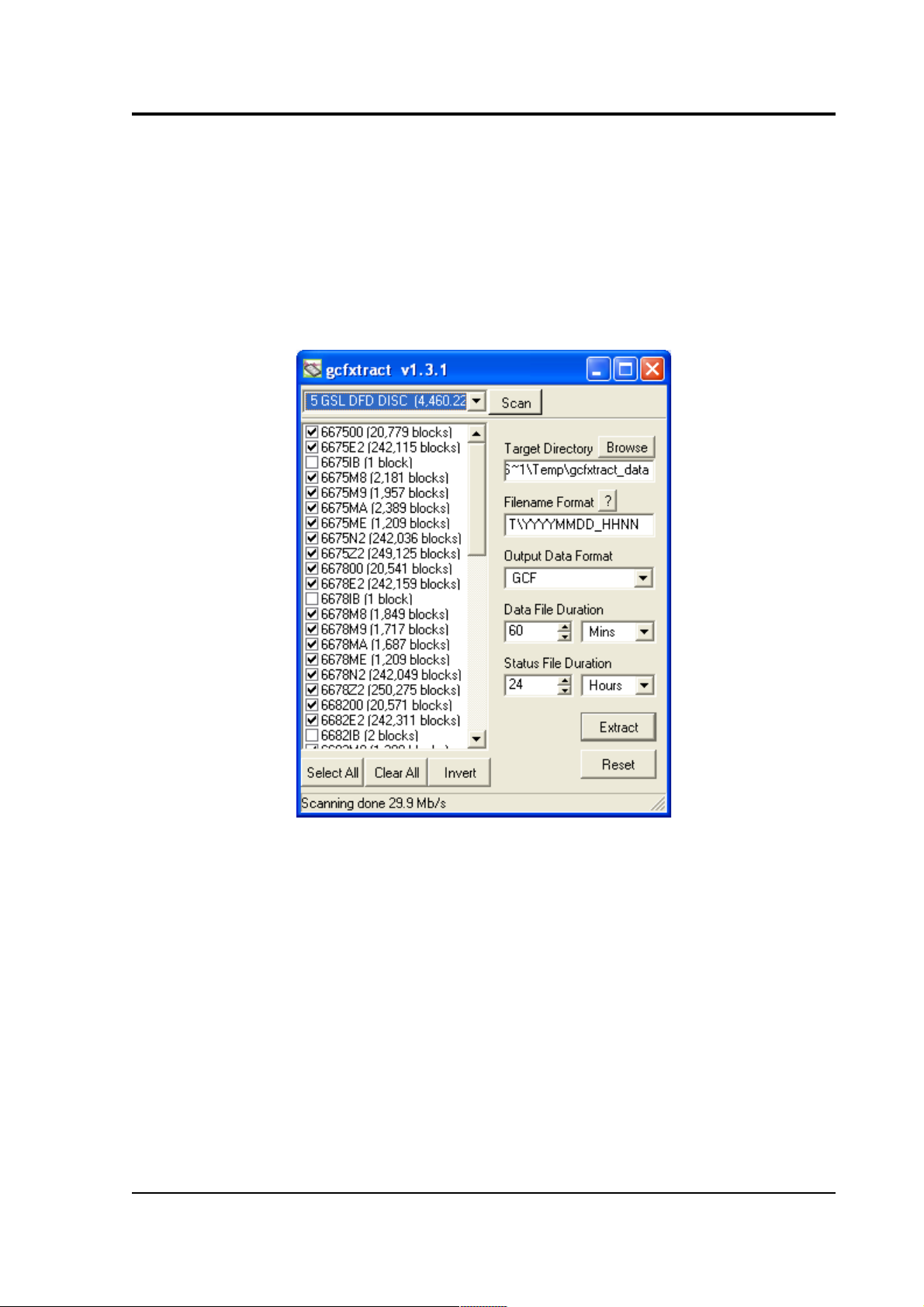
2. Run gcfxtract and select the required disk from the dropdown list, then click Scan.
gcfxtract will scan the disk and display all the streams it
finds in the selection area below. For each stream, the Stream
ID and the number of blocks found are shown.
This operation requires roughly 12 Mb of available memory
for every Gb of space on the disk. If you have a very large
disk, your computer may have to use its hard disk to make
enough space. This will slow down scanning considerably.
3. By default, all streams containing more than 100 blocks are
selected for extraction. You can change which streams to
October 2009 21
Page 22

CMG-DM24
extract by checking or un-checking the check box beside each
stream.
You can check or un-check all of the boxes using the Select
all and Unselect all buttons. Clicking Invert checks all
unchecked boxes, and un-checks all checked boxes.
4. Enter a path name into the Target Directory field, or use the
Browse... button to find a directory. This will be used as the
root directory for extracted data. If it does not exist, gcfxtract
will create it.
5. Enter a format string into the Filename Format field. The
syntax is the same as the format string in Scream! and full
documentation is available by pressing the '?' button beside
the format entry field in interactive mode.
6. Normally, gcfxtract outputs GCF files, to ensure all the
information in the original data is retained. If you want to
convert to a different format, select it from the Output Data
Format drop-down box. gcfxtract can output in most of the
formats supported by Scream!.
7. Data is automatically placed in time order and saved in
multiple files, each file containing a contiguous segment of
data. By default, data streams are recorded in files 60 minutes
long. To change this to some other number of minutes, alter
the value in the Data File Duration (mins) box.
For data streams, if there is a gap in the data, gcfxtract will
start a new file anyway.
Status streams are also saved in in multiple files, but have a
default length of 24 hours. To change this, alter the value
under Status File Duration (hours).
8. When you are happy with the settings, click Extract to begin
extracting the data.
9. Clicking Reset sets a flag on the disk which marks it as
empty. Next time a digitizer wants to transfer data, it will
begin at the beginning of the disk, overwriting the old data.
When this happens, none of the old data can be extracted
with gcfxtract or Scream!. Until then, however, you will still
be able to retrieve all the data.
22 Issue N
Page 23

Operator's guide
10. When you are finished, you should exit gcfxtract and then
use your operating system's standard facility for un-mounting
hardware (e.g. “Safely Remove Hardware” under Windows)
before disconnecting the drive.
You can also read disks with Scream!. This allows you to view data in
the process of being transferred, but is slightly slower, because
Scream! does not read data in strict order. To read a disk with
Scream!:
1. Attach the disk to your computer. You can use FireWire, USB,
or any other interface supported by both your PC and the disk.
2. Run Scream!, and select File → Setup... from the main menu.
Select the Files tab.
3. Set the Base Directory, Filename Format and Data Format as
described above. Also, if required, set the Post-processor and
Granularity options to suit your requirements. Consult the
Scream! documentation for details.
4. Select the Recording tab, and check Auto Record—Enable for
Data Streams and Auto Record—Enable for Status Streams.
Click OK. Scream! will remember the recording options you set
in steps 3 and 4 for later occasions.
5. Select File Read SCSI disk... → from the main menu. Scream!
will search for attached disks, and open a window with a list of
all the streams it has found.
6. Select the streams you want to replay, and click Open. The disk
will appear in the left-hand pane of Scream!'s main window,
and the streams you have selected will start playing into the
stream buffer, as well as being recorded.
7. When you have finished transferring the data, if you want to
reset the disk, select File Reset SCSI disk... → from Scream!'s
main menu. Select the disk you want to reset, and click OK.
October 2009 23
Page 24
CMG-DM24
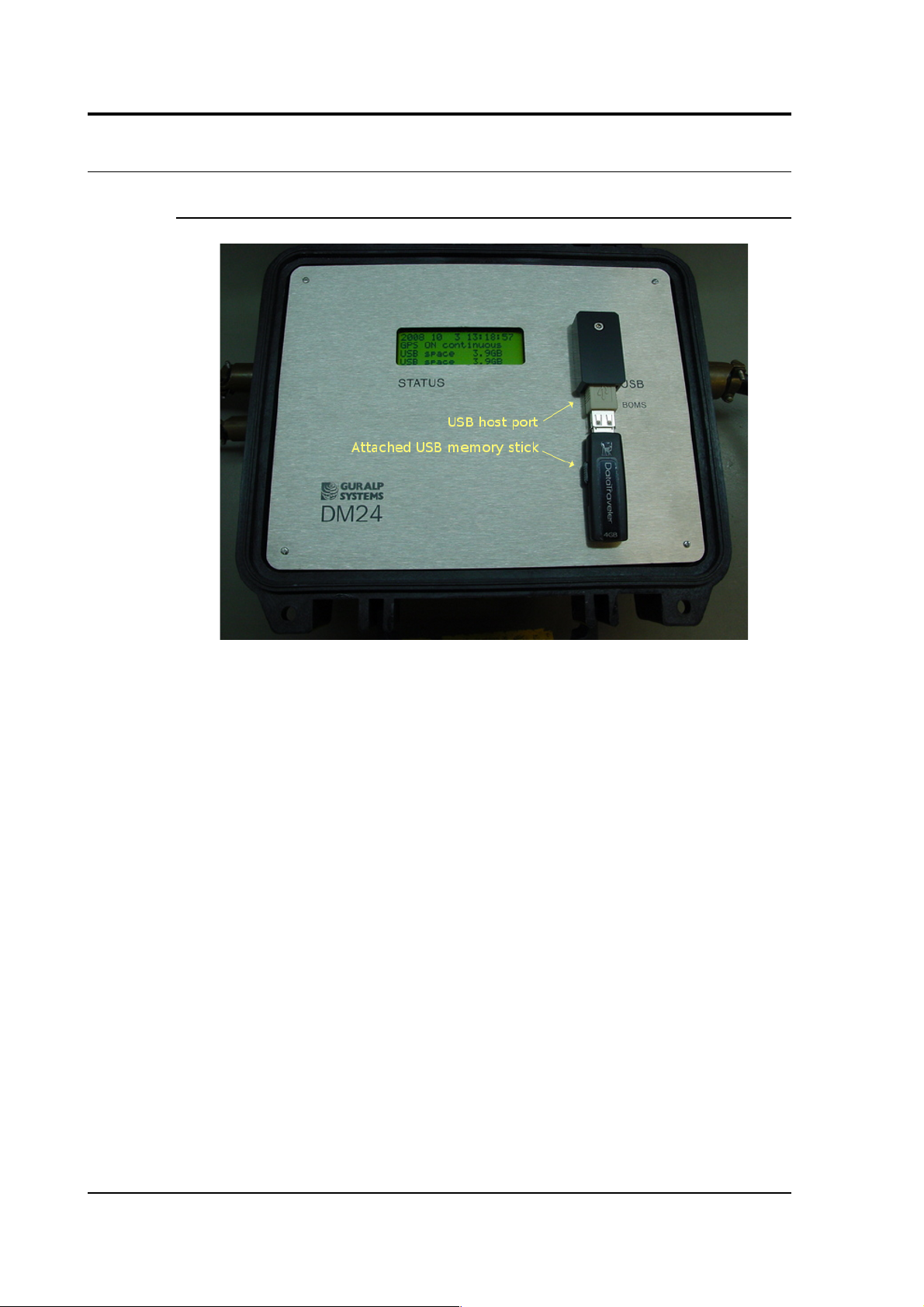
3.6 DM24 USB Host Operations
DM24 Mk3 USB host option
This interface enables the DM24 to record GCF data to a standard USB
disk drive or Flash memory stick using the ISO 9293 FAT filing
format – readable by Linux, DOS, Windows and Mac OS.
Equipment fitted with the USB Host Port connector (labelled
USB BOMS – Bulk Only Mass Storage) will automatically record the
current real time data to the USB device when it is plugged in.
To do this, the DM24 should be in DIRECT or DUPLICATE
transmission mode so that real time data is being fed to the standard
transmit buffer used for normal serial data transmission. The USB
process runs in parallel with the serial transmit thread using the data
in the transmit buffer. It does not matter whether the serial port is
connected or not.
Other transmission modes do not pass useful data via the serial port
and so cannot be used with USB devices. In particular FILING mode
saves all data to the internal flash memory (for later download via the
serial port or FireWire interface) and only outputs “heartbeat” status to
the serial port to inform systems monitoring the port that the unit is
present and operating. FIFO and ADAPTIVE modes use the internal
flash as an extension to the serial transmit buffer as explained in
24 Issue N
Page 25

Operator's guide
section 3.3, on page 15. As no contiguous streams are sent via the
serial port in these modes, nothing will be written to the USB device.
To record data to a USB device, the system should be configured in
DIRECT or DUPLICATE mode – in DUPLICATE+REUSE mode the
DM24 will always have the last 64Mb or more of data in its internal
flash – the firmware does not currently support transferring data from
the DM24 internal flash to a USB device.
Formatting a USB device
If you wish to use a USB device it must be formatted with 16 Kilobyte
clusters. In Windows 2000, XP and Vista open a command prompt and
type:
format e: /fs:fat32 /a:16k
replacing e with the letter of the drive which you wish to format.
Directory structure
The system creates the following directory (folder) structure:
The main directory is \GURALP
Beneath this is a sub-directory named after the DM24's system ID (e.g.
GSLA) within which will be a further sub-directory for each stream the
system is configured to produce. For example:
C838Z2 tap2, vertical component at selected sample rate
C838M8 vertical component mass position
C83800 the digitizer's status stream
Data for each stream is recorded as files within the corresponding subdirectory. The file name is simply the date and time of the first sample
in the file, given in the format YYMMDDHH.xxxx
For example:
08102314.gcf 2008 Oct 23 14:00 – data file
08102312.txt 2008 Oct 23 12:00 – status/text file
The amount of data in each file (granularity) depends on both the
stream sample-rate and type. It can be configured using the
October 2009 25
Page 26

CMG-DM24
HOURFILES command, which takes four parameters (which precede
the command – see chapter 5, page 51 for details of the DM24's
internal FORTH interpreter):
FAST SPS SLOW STATUS HOURFILES
FAST specifies the file size, in hours, for sample rates ≥ SPS
SLOW is the size, in hours, for lower sample rates < SPS
STATUS is the size, in hours, for status stream files.
The default settings are:
1 40 4 12 HOURFILES
With these settings, the system will start a new file every hour for
streams with a sample rate ≥ 40 samples per second.
Lower sample rate streams will have files which last 4 hours – so the
file names will have the sequence “YYMMDD00, YYMMDD04,
YYMMDD08” etc.
Status files will have 12 hour granularity i.e. “YYMMDD00 and
YYMMDD12”.
Note that status streams are recorded as plain text files with the
extension '.txt'.
All other streams are recorded with the extension '.gcf' which is the
same format used by 'Scream!' (i.e. a series of 1k 'gcf' data blocks),
consequently the files can be viewed and processed by Scream!,
simply by “drag and dropping” or right-clicking to select the option.
Due to bandwidth and processing limitations, it may not always be
possible to record continuous streams with particularly high sample
rates. Note that when triggers are in use, the sample rates of streams
transmitted over the serial port will typically increase considerably. If
your application involves sample rates higher than 250 samples per
second, you should verify to your own satisfaction correct operation
(under triggered conditions, if necessary) with your own USB devices
before permanent installation.
26 Issue N
Page 27

Operator's guide
System operation
USB memory sticks and disk drives normally have an LED indicating
activity. This will flash as each block is written, so a few flashes every
10 seconds would be expected from a DM24 producing 100 sps data.
Since data blocks are recorded to their corresponding files in real time,
only the current/latest block can be lost when a USB stick is detached;
all other stream files will have been closed/saved.
When a USB stick is plugged in, the system interrogates it to
determine the free space. This operation can take a minute or more
depending on the capacity of the USB device. When the operation has
been completed, the system reports the available space using the LCD
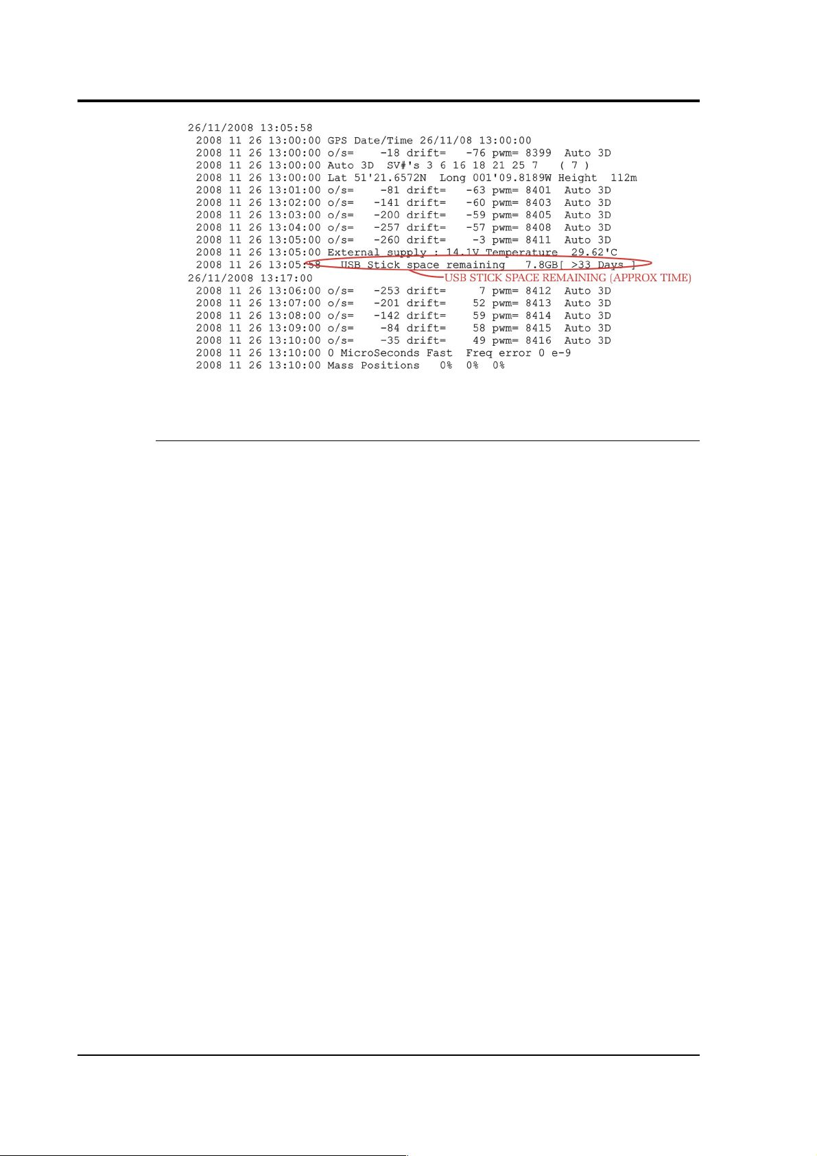
and, also, in the status stream, as in the example below:
2008 10 3 13:18:49 USB Flash stick Recording started NO NAME
D:/>
USB File granularity :
For sample rates >= 40 sps : 1 hour files otherwise 4 hour files
except status ; 12 hour files
2008 10 3 13:19:52 USB Stick space remaining 3.9GB
The system will regularly (after each 5MB of data storage – typically an
hour or 2 of running) report the space available in GB/MB and as a
predicted duration in days/hours (based on the utilization rate for the
previous 5MB).
Recording to a USB device stops automatically when there is less than
100k free space. To record more data, the device must be replaced with
a freshly formatted one.
USB devices can be removed/replaced at any time, but the system does
not additionally buffer the data so a small amount will be lost during
the changeover. In DUPLICATE mode all data would also still be in the
internal flash.
An example of a status display is shown below. This is taken from the
status stream (*00) of a DM24 fitted with a USB host controller after
several minutes of operation.
October 2009 27
Page 28
CMG-DM24
Note for v103 Build 78 firmware.
This build displays additional status information on the LCD panel to
show when the USB stick is being written to and when it is not being
accessed.
It is recommended that the memory stick is only removed when the
display shows USB free, which is followed by a bar graph
indicating a 5 second countdown.
The USB device should not be removed while the display shows
USB BUSY WAIT or while it is scrolling the earlier status
information.
When the stick is initially inserted the LCD panel will report, after a
short delay, access to the stick. This is while the system is calculating
the free space available, which may take many tens of seconds.
28 Issue N
Page 29

Operator's guide
4 Using Scream!
Scream! is a versatile seismic data visualisation program for Güralp
instruments which runs on Windows and Linux computers. If a
DM24's DATA OUT port is connected to an RS232 port on a computer
running Scream!, the program can be used to analyze digitized data
from the DM24's connected analogue sensors, and to control/configure
both the digitizer and the sensors themselves. Scream can also work
with network-attached digitizers.
Scream! is available for free download from Güralp Systems, or may
have been supplied with your equipment.
4.1 Configuring digitizers
Scream! distinguishes between configuration and control of digitizers.
The most important difference is that a digitizer may be controlled
through Scream! at any time whilst it is acquiring data, whereas
configuration options only take effect after a reboot (with consequent
loss of data).
To change the configuration of any connected digitizer:
1. Locate the digitizer you want to configure. All connected
digitizers have an entry in the tree on the left of Scream!'s main
window. If the digitizer is transmitting data through a remote
server or DCM, you may need to “unroll” the entry for that
server (by clicking on the icon) to see the digitizers connected
to it.
2. Right-click on the digitizer's entry (not the icon for the server or
any Comxx icon). Digitizers are shown with icons depicting a
coloured cylinder.
3. Click Configure.... Scream! will then contact the digitizer and
retrieve its current configuration, a process which will take a
few seconds. This done, the Configuration setup window will be
displayed.
4. Once you are happy with any changes you have made in the
Configuration Setup window, click UPLOAD to send them to the
digitizer and reboot. This will take a short while.
To control a digitizer whilst it is running, either right-click on the
digitizer's entry in the list and click Control..., or double-click the
entry. In either case Scream! will contact the digitizer to retrieve
October 2009 29
Page 30

CMG-DM24
control information and display the Control window. The options you
can control immediately are:
• the type of sensor you are using;
• GPS power cycling options;
• the short-term and long-term average values for triggering (but
not which streams perform the trigger, or which are output by
it);
• the length of pre-trigger and post-trigger periods;
• calibration signal options; and
• mass control functions.
Some of these options can also be altered in the Configuration setup
window. For more information on the Control window, see Section 4.2,
page 44.
If you need a more powerful interface to the DM24, you can also issue
commands to it directly using Scream!'s terminal mode. A terminal
window is opened by right-clicking on the digitizer's entry in the list
and selecting Terminal.... The digitizer will stop transmitting data
while you have a terminal window open. Data collected whilst the
terminal is active will be stored for transmission later, memory space
permitting.
The remaining sections of this chapter describe in detail the
configuration options available for the DM24.
30 Issue N
Page 31

Operator's guide
System ID
The System ID pane gives information about the digitizer and its
internal software, and allows you to change GPS timing parameters.
System Identifier and Serial Number : The digitizer type is identified by
its system identifier and serial number. Every data and status block
generated by the digitizer includes these two fields at the beginning, so
that the block’s origin can be identified. On delivery from the factory,
the system identifier and the serial number are set to the GSL works
order number and the digitizer’s serial number, but any combination
of letters A-Z and numbers can be used, such as an abbreviation of
your institution’s name, etc. The system identifier can be up to 5
characters long, whilst the serial number cannot be longer than 4.
Sensor Type : If the sensor attached to the digitizer is a Güralp velocity
sensor, useful seismometer functions (such as sensor locking, centring,
and calibration) may be controlled through the digitizer. The Sensor
Type you set here determines which functions will be available
through the Scream! digitizer configuration set-up interface or through
interactive commands.
GPS Type : The digitizer needs to be able to time-stamp accurately all
data that passes through it. It can set its clock either by receiving time
signals from the GPS satellite network using an attached Garmincompatible (NMEA output) unit, or by taking time information from a
central site (stream sync mode). In stream sync mode, the digitizer
October 2009 31
Page 32

CMG-DM24
expects to receive two-byte packets from the central timing source,
which may have its own GPS unit, or take signals from one of the radio
time standards. Choose the mode you require from the drop-down
menu.
Enable GPS power cycling : If you are using a GPS unit to receive time
signals, but do not experience significant drift in the system's clock
(for example, in a stable-temperature environment), you can save
power by selecting Enable GPS power cycling. With this option in use,
the GPS time is only checked at intervals of a specified number of
hours. Disabling this option keeps the GPS unit running constantly; if
you have ample power, this will give the most accurate results. You
can choose any whole number of hours for the interval.
Output control
The Output control tab allows you to configure which data streams are
sent to Scream! from the digitizer.
Güralp digitizers initially sample incoming data at a high rate (e.g.
2000 Hz for the DM24), which is then filtered and reduced to a lower
rate (decimated) using an on-board digital signal processing unit, or
DSP. The DSP has several filtering/decimation stages, which run one
after the other. Stages which can produce output are called taps. The
Güralp DM24 can output 4 taps simultaneously.
32 Issue N
Page 33

Operator's guide
Each configurable tap can be set to a different decimation factor by
choosing values from the drop-down menus on the left. Decimation
factors of 2, 4, 5, 8, and 10 are available. The numbers visible in the
drop-down menu of each tap are the data rates that each of the
possible decimation factors will provide, given the settings of the taps
above it. Only integer (Hz) data rates are allowed: thus, for example, if
one tap emits data at 25 Hz, the only possible further decimation factor
is 5.
To the right of each decimation factor menu is a grid of check-boxes.
These boxes mark which streams of data to generate at each sample
rate. The screen-shot above shows a possible configuration for a
triaxial instrument. Every channel of the digitizer may be output at
any tap; In the example above, all three axes are being output at Tap 2
(20Hz). The DM24 MkIII has a fourth channel for external input and
calibration, which can also be output at any tap.
If you want to change the names used for the channels, click in the
white box containing a Z in the above picture, and type a letter or
number. It will name the channels with a sequence of letters or
numbers beginning with the one you choose (e.g. A, B, C; 2, 3, 4; 9, A,
B), unless you type Z in which case they will revert to Z, N, and E.
Each combination of channel and tap has two check-boxes:
• Checking the upper check-box of each pair makes that tap
output data continuously for that component;
• Checking the lower check-box makes that tap output data only
when a trigger is active.
In the example above, the digitizer will output data continuously for
all three channels at Tap 2, but never for any other taps. If you do not
need all the streams to output at all rates, you should leave boxes
unchecked to save communications capacity.
You cannot check both continuous and triggered output for the same
channel and tap.
When you enable a triggered stream, the digitizer will output data in
that stream only when a particular set of trigger criteria are met. To
remind you that the streams are not continuous, the window shows
the data streams (lines) passing through a “switch”.
October 2009 33
Page 34

CMG-DM24
In the example above, we might want the high-rate data from Tap 0 to
be generated only when an event registers. To do this, the lower checkboxes of Tap 0 should be ticked:
With this configuration uploaded, Tap 2 will continue to produce
output at all times, but Tap 0 will also emit data whenever the trigger
criteria are met. The Triggering button is now shown in red to remind
you that the trigger is active.
When a trigger occurs, every checked box in this window will cause
the digitizer to output a data stream. This stream will appear in
Scream!'s main window when Scream! first receives some data from it.
Every stream is identified by a 6-character code, where the first four
characters identify the digitizer, and the last two characters identify
the individual stream. The first four characters are set by default to the
serial number of the digitizer; you can change this on the System ID
pane (see above) or from the digitizer's console.
Using the example above, there are three data streams, Z, N and E,
which each output data at 20 samples/s (continuously) and 200
samples/s (occasionally).
34 Issue N
Page 35

Operator's guide
In this example:
• DA79 is the serial number of the digitizer.
• Stream Ids ending Z0, N0 and E0 correspond to input
channels Z, N, and E, with output derived from Tap 0.
• Stream Ids ending Z4, N4 and E4 correspond to input
channels Z, N, and E, with output derived from Tap 2.
Scream! can replace these designations with more helpful
names if you wish: see the Scream! manual or online help for
more details.
• DA7900 is the digitizer's status stream (notice its zero sample
rate).
Triggering
In its standard configuration, the DM24 outputs continuous data at a
sample rate you specify. In addition to this, Güralp digitizers can run a
triggering algorithm on the data they acquire. This allows you to
record data continuously at a relatively low sample rate, but record at
a much higher sample rate during short periods when the trigger is
active. The parameters controlling the triggering algorithm, and
controlling the data output once the system is triggered, are all
selectable by the user, permitting maximum flexibility of operation
and the most efficient use of available storage space.
October 2009 35
Page 36

CMG-DM24
The DM24 can be set up for triggered output, that is, to output certain
data streams only when a particular trigger criterion is met. The trigger
criterion can be tested with data from the same or some other stream.
For example, you could use a later tap (with a lower sample rate) as a
trigger for output from an earlier, more detailed tap. Scream! 4 also
allows you to configure each digitizer to receive triggers from other
digitizers.
To create a new stream with a trigger, open Scream!'s Digitizer
configuration window for the relevant digitizer, and click on the
Output control tab. In the Output control pane, a tap which gives rise to
a triggered stream has a tick in the lower row of its grid of check-boxes.
You cannot configure the trigger criteria until you have selected at
least one stream to be affected by the trigger.
Once you have decided which streams should be output when the
trigger is activated, you will be able to click on the Triggering button
to describe the trigger condition. Alternatively, click on the Triggering
tab at the top of the window. Either action will open the Triggering
pane:
There are two triggering algorithms which Güralp digitizers can use.
However, not all models can use both methods. Scream! will
interrogate the digitizer to discover which methods are supported by
its on-board software.
In addition, some digitizers support external and software triggering.
36 Issue N
Page 37

Operator's guide
STA/LTA – Triggering by average values
The STA/LTA algorithm applies a simple short-term average – longterm average calculation to the triggering stream. It works by
identifying sections of an incoming data stream when the signal
amplitude increases. The purpose of taking a short term average,
rather than triggering on signal amplitude directly, is to make it less
likely that spurious spikes will trigger the device. Averaging also
introduces an element of frequency selectivity into the triggering
process.
You can select which tap is tested for the trigger from the Data source
drop-down menu. The tap does not have to output data to Scream! for
you to be able to use it here.
Any or all of the channels available at that tap may be used to
determine a trigger. You can select which channels are considered by
checking the boxes in the Channel column of the table. If any of the
checked channels passes the trigger condition, the trigger will activate,
and will remain active until all of the checked channels have fallen
below their respective ratio values.
The STA and LTA columns allow you to set the intervals over which
the two averages are calculated, in seconds. Typically, the time
interval for the short term average should be about as long as the
signals you want to trigger on, while the long term average should be
taken over a much longer interval. Both the STA and LTA values are
recalculated continually, even while a trigger is active.
The Ratio column determines by what factor the STA and LTA must
differ for the trigger to be passed. Finding the ratio most suited to your
needs is best done by experiment. Too high a value will result in
events being missed, while too low a value will result in spurious nonseismic noise triggering the system. Like the averages, their ratio is
continuously recalculated for all components. Note that none of the
boxes are allowed to be empty, and so you will need to enter the new
value before removing the old one. Alternatively, you can use the up
and down cursor keys to change the values.
October 2009 37
Page 38

CMG-DM24
For example, setting the STA to 1 second, the LTA to 10 seconds and
the Ratio to 4 would give rise to the following trigger behaviour:
Usually, the values of the STA and LTA periods, and of the Ratio, will
be the same for all checked channels. For convenience, Scream! will
automatically fill in other values to match ones you enter. If you want
to use different values for some channels, you should un-check the
Common values box before altering them.
Once you have enabled the STA/LTA triggering method on a particular
channel, you can use the Control window to change the values of the
38 Issue N
Page 39

Operator's guide
STA and LTA periods, together with the Ratio, without restarting the
digitizer (see Section 4.2, page 44).
Since it is not generally advisable to trigger from broadband data, the
digitizer provides a set of standard bandpass filters to apply to the data
streams before they are tested for the trigger condition. This filtering
serves to maximise sensitivity within the frequency band of interest,
and filter out noise outside this band. You can select which bandpass
filter to use from the Bandpass filter drop-down menu. The corner
frequencies of the pass band of the filter are determined by the Nyquist
frequency, which is derived from the sampling rate of the triggering
data. The three filter options have pass bands between 10% and 90%,
between 20% and 90% and between 50% and 90% of the data’s
Nyquist frequency, respectively.
The possible filter configurations are shown in the following table:
Rate (samples/s) Bandwidth 1 (Hz)
Bandwidth 2
(Hz)
Bandwidth 5
(Hz)
1000 50 – 450 100 – 450 250 – 450
500 25 – 225 50 – 225 125 – 225
400 20 – 180 40 – 180 100 – 180
250 12.5 – 112.5 25 – 112.5 62.5 – 112.5
200 10 – 90 20 – 90 50 – 90
125 6.25 – 56.25 12.5 – 56.25 31.25 – 56.25
100 5 – 45 10 – 45 25 – 45
50 2.5 – 22.5 5 – 22.5 12.5 – 22.5
40 2 – 18 4 – 18 10 – 18
25 1.25 – 11.25 2.5 – 11.25 6.25 – 11.25
20 1 – 9 2 – 9 5 – 9
10 0.5 – 4.5 1 – 4.5 2.5 – 4.5
8 0.4 – 3.6 0.8 – 3.6 2 – 3.6
5 0.25 – 2.25 0.5 – 2.25 1.25 – 2.25
4 0.2 – 1.8 0.4 – 1.8 1 – 1.8
2 0.1 – 0.9 0.2 – 0.9 0.5 – 0.9
1 0.05 – 0.45 0.1 – 0.45 0.25 – 0.45
October 2009 39
Page 40

CMG-DM24
As can be seen, the filter you choose defines the set of permissible
sample rates.
The spectral amplitudes for the various frequency responses available
are shown in the figures below.
Level triggering
Using the Level triggering method, a trigger is generated whenever one
of the checked components reaches a certain level above the baseline.
You can select which tap is monitored from the Data source drop-
40 Issue N
Page 41

Operator's guide
down menu, and the channel(s) to be considered from the Channel
column of the table. The values in the Level column are the number of
counts above the baseline that channel must reach before a trigger is
generated.
As with the STA/LTA method, the values of the Level will often be the
same for all checked channels. If you want to use different values for
some channels, you should un-check the Common values box before
altering them.
Once you have enabled the Level triggering method on a particular
channel, you can use the Control window to change the level at which
the system triggers without restarting the digitizer.
External triggering
When a digitizer or digital sensor triggers, it signals the fact to
connected devices, as well as sending any extra data that it has been
configured to transmit. You can configure other digitizers to respond
to this signal by triggering in turn. This is an option which you can
specify at the time of manufacture. See Section 6.3, page 97, for details
of how to set up an installation for external triggering.
As an example, to instruct a stand-alone digitizer with digital inputs to
respond to triggers generated by an attached digital sensor:
1. Open the Configuration setup window for the digital sensor, and
check Enable External Trigger Output - this causes it to send
triggers to connected devices;
2. UPLOAD the new configuration to the digital sensor;
3. Open the Configuration setup window for the digitizer, and
check Enable External Trigger Input - this causes it to listen for
triggers coming from the digital instrument, and to record data
from any attached analogue instruments when it receives one
(depending on its Output control configuration); then
4. UPLOAD the new configuration to the digitizer.
If a digitizer has both Enable External Trigger Output and Enable
External Trigger Input selected, it will record data when it receives an
external trigger as if it had triggered itself, but it will not relay the
trigger on to other digitizers. It will only send a trigger message if its
own triggering criteria are satisfied. This prevents triggering loops.
October 2009 41
Page 42

CMG-DM24
Pre-trigger and post-trigger recording
In order to capture all of a seismic event, it is often useful to be able to
record data immediately preceding the trigger. Güralp digitizers have
an internal buffer of some seconds which allows this data to be added
to the triggered stream. Pre-trigger data is particularly useful for
emergent-type signals, where the system does not trigger until one
phase after the first arrival. In addition, to ensure that the coda of each
event is included, some seconds of data are recorded after the system
detriggers.
The two boxes at bottom right of the Triggering pane allow the user to
set the pre-trigger and post-trigger data intervals, in seconds. These
values determine the minimum length of time during which data will
be saved before the trigger condition occurs, and after it has lapsed.
Regardless of the intervals chosen, the data in the triggered streams
will begin on a whole second boundary.
Mux Channels
Güralp digitizers provide a range of slow-rate auxiliary channels for
reporting the system's state of health and other diagnostic information,
known as multiplexed (“Mux”) channels. The number of Mux
channels depends on the model and configuration of your digitizer.
Generally, three channels are used to report the sensor mass position,
and another measures the internal temperature of the digitizer. In
addition to these, up to 12 Mux channels may be supplied for the
user's own purposes. Some digitizers have a separate AUXILIARY port
which can be used to access these channels.
The collection and transmission of Mux channels is controlled using
the Mux Channels pane:
42 Issue N
Page 43

Operator's guide
If a tick is placed in the box next to a channel, its data will be collected
and transmitted as a data stream in GCF format, just as with the
normal data channels. To indicate that the data comes from a Mux
channel, the Stream ID will take the form ****Mx, where M stands for
Mux and x is a hexadecimal integer (i.e. 0 – 9, and A – F for 10 through
15). Z, N/S and E/W Mass Position Mux channels appear as M8, M9 and
MA respectively.
Ports
The Baud Rates pane of the Configuration setup window allows you to
program the baud rate and stop bits for the DM24's output port.
The baud rate you choose must satisfy two conditions:
• It must be high enough to allow all the transmission of all data
generated by the digitizer at the sampling rates you have
chosen. For three streams of data at 100 Hz, for example, 9600
baud will usually be sufficient. If you wish to transmit 200 Hz
data, however, the baud rate must be at least 19200.
• It must be low enough to fit within the bandwidth of the
communications infrastructure you are using. While modern
modems often offer transfer rates up to 56k baud, the telephone
or transmission lines may not support these rates. The same
holds true for radio communication links.
October 2009 43
Page 44

CMG-DM24
Usually, the transmit and receive rates of the data port will be the
same. If not, you may select different data rates by removing the check
in the box marked Identical TX/RX rates.
The Stop Bits option allows you to choose whether the serial link uses
1 or 2 stop bits. In most cases this can be left at 1, although 2 may be
required if you are sending data over ‘difficult’ transmission lines (for
example, some types of radio link). Using 2 stop bits will add a 10%
overhead to the data.
You will also need to set the data rate for Scream's local serial port, as
well as for the SAM/DCM or other communications device (if you are
using one). In Scream!, you can configure a serial port by right-clicking
on its icon (not that of the digitizer) and selecting Configure... from the
pop-up menu: for more details, consult the online help or user guide
for Scream!. If you are using an additional communications device,
you should consult its documentation to learn how to set its baud rate.
4.2 Controlling digitizers
To control a digitizer whilst it is running, either right-click on the
digitizer's entry in the list to the left of Scream!'s main window (not the
Local or Comxx icons) and click Control..., or simply double-click the
entry. Scream! will then contact the digitizer and retrieve its current
status - a process which will take a few seconds - after which the
Control window will be displayed. Once you are happy with any
changes you have made in the Control window, click Apply to send
them to the digitizer, where they will take effect immediately.
This chapter describes the control options available to you for the
DM24. Many of these options will also be available for other Güralp
digitizers. For the most accurate information, you should consult the
Operator's Guide for the digitizer or sensor you connect.
44 Issue N
Page 45

Operator's guide
System
When the Control window is first opened, it will be showing the
System pane.
Sensor Type: If the sensor attached to the digitizer is a Güralp velocity
sensor, you can send control commands to it from the Mass Control tab
(see below). Which functions are available on this tab depends on the
Sensor Type you have set here.
If you change the Sensor Type, you may have to Apply the change,
close the Control window, and open a new one to access the Mass
Control options.
Enable GPS power cycling: If you are using a GPS unit to receive time
signals, but do not experience significant drift in the system's clock
(for example, in a stable-temperature environment), you can save
power by selecting Enable GPS power cycling. With this option in use,
the GPS time is only checked at intervals of the specified number of
hours and the GPS receiver is powered down in between checks.
When the time is checked, the GPS receiver is powered up for as long
as it takes to obtain a satellite “fix” and both synchronize and stabilise
the internal clock. Under extreme adverse conditions, ensuring the
internal clock is stabilised may take longer than the power cycling
interval, in which case the GPS receiver will remain powered up
throughout.
October 2009 45
Page 46

CMG-DM24
Triggering
The Triggering pane is very similar to the corresponding pane of the
Configuration setup window ( see section 4.1 page 35), although not all
of the options described there are available here, since some require
rebooting the digitizer.
Calibration
You can check that your instrumentation is correctly calibrated by
injecting known signals into the sensor's feedback loop. The
Calibration pane allows you to do this once the sensors are installed.
46 Issue N
Page 47

Operator's guide
Each channel Z, N/S and E/W can be calibrated separately. For most
triaxial digital instruments, each channel calibrates the corresponding
axis of the instrument; simply select one of the Z, N/S and E/W check
boxes to calibrate that axis. Some instruments use only one calibration
loop, which is reproduced for all three components: if you have one of
these instruments, you should select Z to calibrate the sensor.
The calibration signal is digitized at the same rate as the highest-rate
data stream you have selected for either continuous or triggered
output. It is returned on a channel ending Cn (n = 0 – 7). The auxiliary
analogue channel is interrupted whilst calibration is active.
The Duration box tells the digitizer how long to provide the
calibration signal before disconnecting. This avoids the system being
inadvertently left in calibration mode. The default is 2 minutes.
All Güralp digitizers can produce either sine-wave or square-wave
(step) calibration signals; newer models can also carry out broadband
noise calibration. The Sine wave calibration signal always starts and
stops on the zero crossing. The frequency or period is given by the
boxes at the top, right-hand side of the dialogue. Only integers
between 1 and 10 may be specified for either frequency or period, so to
generate a 0.5 Hz signal you should select Period and set the time to 2
(seconds). Likewise, if you require a 0.25 second period you should
select Frequency and set the rate to 4 (Hz). In this manner, you can
select frequencies ranging from 0.1 to 10 Hz (10 to 0.1 s periods).
October 2009 47
Page 48

CMG-DM24
You can specify step calibration by selecting the Square wave button.
The square wave consists of a positive step at the start of the next
minute of the digitizer’s internal clock, followed by a negative step
after a specified number of minutes. After a further delay of the same
number of minutes, the calibration signal is disconnected. The default
is 2 minutes. The Period and Frequency settings are ignored.
The Broadband Noise calibration signal consists of a constant stream
of white noise, which lasts for the specified number of minutes. The
Period and Frequency settings are ignored.
Mass Control
Many Güralp instruments respond to control signals to centre, unlock,
and lock the sensor masses. These signals are generated by the
digitizer. You can tell the digitizer to send a signal using the Center
Now, Lock Now and Unlock Now buttons on the Mass Control tab.
If you select Monitor progress, the window will remain open during
the process, and the mass positions will be displayed in the Vertical,
N/South and E/West boxes. If you leave Monitor progress unselected,
the window will close. You can still monitor mass positions by
selecting the appropriate streams and opening a WaveView window for
them.
Depending on which Sensor Type you have chosen in the System tab
(see above), not all the control signals will be available. For example, a
48 Issue N
Page 49

Operator's guide
CMG-3ESP can be centred from Scream, but must be locked and
unlocked manually, whilst a 3T has remote lock and unlock
commands. Conversely, CMG-5T strong-motion instruments must be
centred manually, and do not need locking or unlocking. If you have
set the Sensor Type to CMG-5T or CMG-5TD, the Mass Control tab will
not be available.
Data flow
The DM24 operates in one of several transmission modes and,
independently, in one of several buffering modes. These modes relate
to how the unit uses its Flash memory and are described fully in
section 3.3, page 15.
To select transmission and buffering modes in Scream!, right-click on
the digitizer, then click on Control... and navigate to the Data Flow
pane:
Select the desired Transmission mode to use the flash memory:
• as a simple data store, from which you can request data (FILING
and DUAL modes);
• as a buffer holding unacknowledged blocks, which are
transmitted in preference to real-time data (FIFO mode);
October 2009 49
Page 50

CMG-DM24
• as a buffer holding unacknowledged blocks, which are
transmitted whenever the channel is free but no real-time data
blocks are ready (ADAPTIVE mode);
• not at all (DIRECT mode).
Select the desired buffering mode, which tells the unit what to do
when its Flash memory becomes full: either
• carry on, overwriting the oldest data held, or
• stop writing and switch the DM24 into DIRECT mode.
Clicking Apply in this window immediately activates the transmission
mode you have selected—there is no need to reboot.
If you prefer, you can use the DM24 terminal to switch between
transmission modes, as described in section 5.9, page 77.
50 Issue N
Page 51

Operator's guide
5 Command line interface
5.1 Introduction
You can connect to the internal software of the DM24 over its output
serial port and communicate with it.
To enter command mode from Scream!, right-click on the digitizer's
icon and select Terminal... from the menu that pops up. A window
will open, and once the digitizer and computer are communicating
properly you will see the prompt
ok
If you prefer, you can use a terminal program on your computer (such
as minicom on Linux, or hypertrm on Microsoft Windows) to
connect to the DM24.
Whilst you are in terminal mode, data transfer will be interrupted; the
digitizer may use any Flash memory as a temporary store, depending
on how you have configured it. Some commands, such as SET-TAPS,
require a reboot to take effect.
When you are finished with your command-line session, simply close
the Scream! or emulator window. Scream! will automatically issue
the GO command to resume data-stream transmission. The session
will, in any case, time-out after a minute. If this happens while you
are using minicom or hyperterm, and the digitizer starts transmitting
stream data (which will appear as bursts of unintelligible characters),
key Control-S to interrupt the streams and resume your session.
Güralp EAM modules also allow you to send commands direct to the
digitizer using the command-line tool data-terminal. Older DCM
and AM used the command-line tool gcli. For more information,
please see the manual for your data module.
If you have problems connecting to the digitizer's console, you should
check that the serial port's options and baud rate are set correctly in
Scream! or your terminal program. As supplied, the DM24 expects
connections at 19200 baud, with 8 data bits, no parity bit and 1 stop
bit. No flow control is used.
October 2009 51
Page 52

CMG-DM24
FORTH
The DM24 uses a FORTH interpreter to implement its features. To
issue a command in FORTH, you must supply the arguments before
the command, for example:
3 SENSOR-TYPE
In FORTH, anything you enter is termed a word. New words (case
insensitive) are placed on a stack. Some words are known to the
system, and may represent commands; if a command finds itself at the
top of the stack (e.g. because it is the last thing you typed), they will
execute, remove themselves from the stack, and then remove further
items from the stack to use as arguments. Thus, in the command
3 SENSOR-TYPE
the 3 has no immediate effect, so stays on the stack; SENSOR-TYPE
takes itself and the previous item (here 3) off the stack, then performs
its action on the 3 (here, setting the configured sensor type to 3,
representing a CMG-3T sensor).
If a command completes with nothing remaining on the stack, the
digitizer will show the prompt ok. Otherwise, the prompt will remind
you that the digitizer is waiting for you to complete the command.
Some commands, such as SAMPLES/SEC, clear the stack automatically
after they execute.
Some commands are interactive, and will ask you to provide extra
information after you execute them. In the following sections,
interactive commands are shown as example sessions, where
information you enter is given in medium and messages returning from
the DM24 are given in bold.
5.2 Getting help
The DM24 has an on-board help system which can be accessed with
the commands HELP and EXPLAIN.
HELP
Syntax: HELP
Lists all the commands which are recognized by the digitizer.
If the command you want is not listed:
52 Issue N
Page 53

Operator's guide
• The command may be in the extended dictionary. This
dictionary contains certain advanced commands, as well as
exposing internal digitizer functions and variables. To enable
the extended dictionary, issue the command ok-1 (that's a
number one, not a lower-case 'L').
When you have finished using the extended dictionary, close it
with the command [seal] (including the square brackets), so
you do not inadvertently change the internal settings with
subsequent commands.
• Alternatively, the command may not be implemented in the
firmware version you have installed. Check the Güralp Systems
web site for updated firmware.
EXPLAIN
Syntax: EXPLAIN command
Displays a short message describing the syntax of command and its
effect.
5.3 General configuration
SET-ID
Syntax: SET-ID (interactive)
Sets the system identifier and serial number of the DM24 to values you
supply.
SET-ID
System Identifier ? {ALPHA} DM24
Serial # ? (C23300) C90200
The system identifier you supply may contain up to 5 alphanumeric
(0-9A-Z) characters.
The serial number you supply must contain exactly 6 alphanumeric
(0-9A-Z) characters and should end with two zeroes (0) in almost all
circumstances. The first four characters are copied verbatim into
stream IDs and the final two characters are used as the “base” for
generating stream identifiers. All stream IDs used in this manual
assume that these two characters are zeroes.
October 2009 53
Page 54

CMG-DM24
SERIAL2
Syntax: SERIAL2 (interactive)
Sets the serial number for a second sensor (for seven-channel
digitisers) to a value you supply.
SERIAL2
Secondary Serial # {0} ? 6 characters : C90300
The serial number you supply must contain exactly four or six
alphanumeric (0-9A-Z) characters. However, If six characters are
given, the last two are ignored and replaced with zeroes (see the
discussion of serial numbers at SET-ID, above).
SENSOR-TYPE
Syntax: type SENSOR-TYPE
Tells the DM24 which kind of sensor is attached to it. This affects
whether or not the digitizer exposes commands such as locking and
centring.
type can be one of
• 1, for CMG-40T sensors,
• 2, for CMG-3ESP sensors,
• 3, for CMG-3T analogue sensors, or
• 4, for CMG-3TD sensors.
GPS-TYPE
Syntax: type GPS-TYPE
Tells the DM24 which kind of GPS is attached to it.
type can be one of
• 0, if no GPS is available, or
• 2, for attached GPS equipment using the NMEA protocol.
54 Issue N
Page 55

Operator's guide
HR-CYCLE
Syntax: interval HR-CYCLE
Sets the time to wait between GPS synchronizations.
To save power, the DM24 can switch off the attached GPS receiver
once its internal precision clock has been successfully synchronized.
The GPS receiver is reactivated every interval hours to ensure that
the clock remains correct, and shut down again once the clock error
has stabilized.
Setting interval to zero disables this function, i.e. the GPS will be
powered all the time. This is the best setting to use in installations
with access to mains (outlet) power. The maximum allowed value for
interval is 23.
SET-CLOCK
Syntax: SET-CLOCK (interactive)
Sets the internal clock.
SET-CLOCK
Enter Date & Time YYYY MM DD HH MM SS
2006 02 01 12 53 25 Clock set to 2006 2 1 12:53:27 ok_SBHY
The time should be entered in the form year month day hour
minute second, padding each field with zeroes so that they line up
with the guide above.
If the DM24 does not recognize the time format you have used, it will
output the message:
Invalid Time Entry.
This setting will be overridden when the GPS system next
synchronizes the clock.
TIME?
Syntax: TIME?
Displays the current date and time.
October 2009 55
Page 56

CMG-DM24
LEAPSECOND
Syntax: yyyy mm dd LEAPSECOND
Manually notify the digitizer of an upcoming leap second. This
command is not normally necessary, since GPS already has support for
leap seconds. However, some older GPS receivers did not properly
implement this feature. See SQPATCH, below.
The leap second is taken to be at the end of the day yyyy-mm-dd.
SQPATCH
Syntax: SQPATCH ENABLE or SQPATCH DISABLE
Enables or disables the internal patch for older GPS receivers – those
based on Trimble Lassen SQ units. These units misinterpret the GPS
system's advance notification of a leap second and, consequently, run
one second slow until the leap second occurs.
With SQPATCH enabled, the time reported by the digitizer is offset by 1
second to counteract this problem. If you have set LEAPSECOND,
above, SQPATCH will automatically be disabled when the leap second
occurs and the digitizer will then run normally.
GPS receivers with the latest firmware do not suffer from this problem.
To find out whether SQPATCH is currently enabled, issue the
command
.SQPATCH
AZIMUTH
Syntax: instrument angle AZIMUTH
Some borehole digitizers can rotate incoming signals algorithmically
as they are digitized. This feature allows you to compensate for an
instrument being out of alignment with the North/South axis. To use
it, first measure the orientation of the sensor, then connect to the
digitizer and issue an AZIMUTH command, giving the angle you have
measured.
instrument tells the digitizer which instrument to apply the rotation
to; 0 for sensor A or 1 for sensor B.
56 Issue N
Page 57

Operator's guide
angle is the measured angle of deviation from the North/South axis,
in tenths of a degree. The angle of deviation is the negative of the angle
by which you want incoming signals to be rotated. Like all other
parameters, it must be an integer (i.e. a whole number of tenths of a
degree).
You can measure the orientation of a borehole sensor by placing a
reference sensor nearby and carrying out coherence calculations. An
extension to Scream! is available which can do this for you. For
details, see the manual for your sensor or for Scream!.
The AZIMUTH command only alters the digitizer's CMOS settings. You
will need to re-boot the digitizer to transfer them to the DSP.
CROSS
Syntax: channel CROSS
Alters the DSP's transformation matrix to invert one of the digitizer
channels. channel is one of 0 (vertical), 1 (N/S), 2 (E/W) and 3
(auxiliary).
The CROSS command only alters the digitizer's CMOS settings. You
will need to re-boot the digitizer to transfer them to the DSP.
* If you need to set both AZIMUTH and CROSS, you must issue
AZIMUTH first, since it overwrites the matrix.
5.4 Port configuration
BAUD
Syntax: port baud-rate BAUD
Sets the baud rate for one of the serial ports on the DM24, in bytes per
second. port can be:
• 0, for the DATA OUT port;
• 1, for the GPS port; or
• 2, for the DATA IN port.
For example,
0 38400 BAUD
October 2009 57
Page 58

CMG-DM24
1 4800 BAUD
2 38400 BAUD
This will reset a standard single-sensor DM24 to its default
configuration.
The allowable values for baud-rate are 4800, 7200, 9600, 14400,
19200, 38400, 57600, 115200 and 230400. For compatibility reasons,
1152 is also accepted, setting the baud rate to 115200.
* The GPS port (port 1) should always be set to 4800 baud.
STOPBITS
Syntax: port number-bits STOPBITS
Sets the number of stop bits used for one of the serial ports on the
DM24. port can be:
• 0, for the DATA OUT port;
• 1, for the GPS port; or
• 2, for the DATA IN port.
By default, the DM24 uses 1 stop bit on all ports.
+MODEM
Syntax: +MODEM (interactive)
Instructs the DM24 to use a modem connected to the DATA OUT port
to contact a remote device and transmit data stored in the Flash
memory.
The DM24 can dial out every time it generates a heartbeat message,
and also whenever a trigger occurs. You can change the interval
between heartbeat messages with the HEARTBEAT command, below.
When you issue +MODEM for the first time, the digitizer will prompt
you to enter a telephone number:
+MODEM
Phone# is not set Enter phone# 00441189819056
Phone# 00441189819056 Flash FIFO : Circular Configuration for
dial out ok_DEMO00
58 Issue N
Page 59

Operator's guide
If you have already configured a telephone number, the command will
print out the current setting and ask if you want to change it.
+MODEM
Phone# 00441189819056 New number? y/n y
Enter phone# 00441189819943
Phone# 00441189819943 Flash FIFO : Circular Configuration for
dial out ok_DEMO00
+MODEM also changes the transmission mode of the digitizer to
FILING, so that all incoming data is stored in Flash memory ready to
be downloaded. When the dial-out takes place, all new data in Flash
memory is transmitted. By configuring the DM24 to transmit only
triggered streams, you can create a system which “wakes up” on a
trigger, connects to a data centre using the modem, and delivers the
triggered data in near real time.
–MODEM
Syntax: -MODEM
Disables automatic modem dial-out. Note that this command does not
change the current transmission mode so, if you have previously
issued +MODEM, the DM24 will be left in FILING mode.
If you issue -MODEM over a dial-out modem link, you should make sure
you have arrangements already in place for contacting the DM24 by
other means, since the command will cause the connection to close.
+GCFIN
Syntax: input-port +GCFIN
Instructs the digitizer to accept GCF input on either the GPS or the
DATA IN port. input-port can be:
• 1, for the GPS port; or
• 2, for the DATA IN port.
The GCF streams received will be combined with the DM24's own
streams and output with them through the DATA OUT port or saved to
Flash memory, according to the current transmission mode.
Whilst GCF input is active, the normal function of each port (GPS or
console access) is disabled.
October 2009 59
Page 60

CMG-DM24
–GCFIN
Syntax: input-port -GCFIN
Instructs the digitizer to stop accepting GCF input on input-port,
and to return the port to normal operation.
OPEN
Syntax: OPEN system-id stream-id-prefix (n.b.)
Opens a terminal session to a second, connected digitizer.
The DM24 scans all the ports which are currently accepting GCF input
(see +GCFIN, above) to find a digitizer which matches system-id and
stream-id-prefix.
For stream-id-prefix you should use the first 4 characters of the
Stream IDs produced by the required digitizer, i.e. without the
component and tap designations.
A terminal connection is then made to the second digitizer, allowing
you to issue commands.
To finish the session and return to the first digitizer's terminal mode,
use the command GO.
USBPORT
This command is only available on units with the optional USB
interface.
Syntax: port USBPORT
Instructs the digitizer to redirect input or output from port port to the
USB interface. You can then attach the USB port to your computer
with a suitable cable, where it will appear as an additional serial port
with a significantly faster data transfer rate. The value for port can be:
• 0, for the DATA OUT port;
• 1, for the GPS port; or
• 2, for the DATA IN port.
60 Issue N
Page 61

Operator's guide
The USB interface is provided by an internal FTDI245 chip, which is
compatible with Microsoft Windows, Linux and Apple Macintosh
systems.
You can use the USB port only to connect to a computer, not directly
to a peripheral (e.g. a hard disk). If you want to download data to a
hard disk, you should specify the FireWire interface instead.
5.5 Output configuration
SAMPLES/SEC
Syntax: tap-0 tap-1 tap-2 tap-3 samples/sec
The DSP software on the DM24 supports up to 7 cascaded
filter/decimation stages. At each stage, the sample rate can be divided
by a factor of 2, 4 or 5. The internal ADC outputs data at 2000 samples
per second, so decimated data streams are available from 1,000, 500
and 400 samples/sec down to 1 sample/sec.
You can specify the sample rate to use at four of these stages, known
as taps. You can also take output from any of these four stages. The
DM24 will arrange the remaining stages according to your settings.
The arguments tap-0 to tap-3 are the sample rates at each tap in
turn, starting with the highest. You must ensure that each rate is lower
than the previous one by a factor of 2, 4, 5, 8 (= 2 then 4), 10 (= 2 then
5) or 16 (= 4 then 4). Non-integer values are not allowed.
For example:
1000 125 25 5 samples/sec
1000 500 100 10 samples/sec
500 100 20 4 samples/sec
400 40 10 5 samples/sec
As long as you specify the initial taps, you can omit later ones. The
command fills in the value of the missing taps, using a decimation
factor of 2 where possible. Thus, the following commands are
equivalent:
400 40 20 10 samples/sec
400 40 samples/sec
October 2009 61
Page 62

CMG-DM24
* Currently the DM software does not support the new GCF format for
higher sample rates. It also does not properly support 250 samples/s,
nor rates below 1 sample/s.
CONTINUOUS
Syntax: tap components CONTINUOUS
Sets which components are output under normal conditions, and at
which tap(s).
tap is the tap number at which to output the triggered stream. You
can set which taps output which sample rate using the SAMPLES/SEC
command, described above.
components is an integer below 16, whose binary bits represent the
Z (1), N (2), E (4) and auxiliary (8) components respectively. Thus, for
example:
• 0 1 CONTINUOUS will output the Z component only (1) at the
first tap;
• 0 2 CONTINUOUS will output the N component only (2);
• 0 4 CONTINUOUS will output the E component only (4);
• 0 7 CONTINUOUS will output all three directional components
(1 + 2 + 4 = 7);
• 0 12 CONTINUOUS will output the E component and the
auxiliary component (4 + 8 = 12);
• 0 0 CONTINUOUS will output nothing at the first tap.
SET-TAPS
Syntax: tap-0 tap-1 tap-2 tap-3 SET-TAPS
This is an alternative to the CONTINUOUS command, which allows you
to set the outputs for all taps simultaneously.
tap-0 to tap-3 are integers below 16, whose binary bits represent the
Z (1), N (2), E (4) and auxiliary (8) components respectively. Each one
sets which components are output at that tap under normal
conditions.
62 Issue N
Page 63

Operator's guide
For example, if you issue
9 7 0 15 SET-TAPS
• tap 1 will output Z and the auxiliary component ( 1 + 8 = 9 );
• tap 2 will output all three directional components ( 1 + 2 + 4 =
7 );
• tap 3 will not output anything; and
• tap 4 will output all four components ( 1 + 2 + 4 + 8 = 15).
To set triggered output streams, you should use the TRIGGERED
command detailed below.
COMPRESSION
Syntax: bits size COMPRESSION or NORMAL COMPRESSION
Sets the maximum amount of compression to use. Greater
compression means the digitizer outputs data more efficiently, so more
can be transmitted over a link with a given bandwidth. However,
compressing streams uses processor power and can increase data
latency.
The digitizer compresses data without loss, so compression is most
effective when the data contains relatively little information. In most
cases, when a seismic event occurs, the digitizer will need to decrease
the compression level.
bits can be one of 8BIT, 16BIT and 32BIT. 8BIT (the default) is the
maximum amount of compression; 32BIT denotes no compression.
size determines the maximum number of data samples in a GCF block.
This must be between 20 and 250; the default is 250.
GCF blocks must be a whole number of seconds long. If you set size to
a very small value, so that size samples is less than 1 second for some
streams, the digitizer will output 1 block every second for those
streams, ignoring the value of size.
Thus, if you issue 32BIT 20 COMPRESSION, streams with a sample
rate of 20 samples/s and higher will output one block per second,
whilst lower rate streams will output 20-sample blocks: every 5
seconds for 4 samples/s data, etc.
October 2009 63
Page 64

CMG-DM24
The special value, NORMAL COMPRESSION, returns the setting to its
default value, equivalent to 8BIT 250 COMPRESSION.
LOWLATENCY
Syntax: LOWLATENCY
This is a special mode for applications requiring lower sample rate
data in as close to real time as possible. In this mode, the digitizer
takes a 200 samples/s stream and passes it through low-pass and
decimation filters internally, before exposing it as a 20 samples/s
stream at an increased rate of 1 block per second.
To enable low latency mode on all three components, first use
SAMPLES/SEC to set Tap 0 to 200 samples/s, then issue the following
commands:
NORMAL COMPRESSION
0 7 CONTINUOUS
0 1 BANDPASS
LOWLATENCY
7 TRIGGERS
If you want to enable low latency mode on some components only,
replace the 7s above with another value (e.g. 1 = Z, 2 = N, 4 = E).
To disable low latency mode, issue
0 1 BANDPASS
0 TRIGGERS
When LOWLATENCY is active, the TRIGGERS and BANDPASS
commands have special meanings. Because of this, the STA/LTA
triggering function is disabled. You can still use LEVEL triggering if
you require (see below).
SETDSS
Syntax: output-spec SETDSS
This command alters the way the DM24 outputs its status streams.
In normal operation, the DM24 stores lines of status information until
it has filled a 1K GCF block. For low latency applications, however,
status information is required more frequently. In this mode, the
DM24 will output a status block every minute. This mode is required
by the DSS server distributed with Güralp Systems' CMG-DCM.
64 Issue N
Page 65

Operator's guide
output-spec is an integer below 32, whose bits tell the digitizer
which status lines to output.
● Setting bit 0 (1) produces lines showing the current internal
clock offset, frequency error, and GPS fix type. For example:
2006 9 4 13:13:00 2 MicroSeconds Fast Freq error 0 e-9
Auto 3D [-4]
● Setting bit 1 (2) produces lines showing the current GPS offset,
drift, PWM measure, and fix type. For example:
2006 9 4 13:13:00 o/s= 340 drift= 0 pwm= 8382 Fix= "3D"
● Setting bit 2 (4) produces lines showing the GPS latitude and
longitude. For example:
2006 9 4 13:13:00 Lat= "51'21.6526N" Long="001'09.8148W"
● Setting bit 3 (8) produces lines like
Boot Log : Power_cycles= 11 Watchdog_resets= 51
Last boot 2006 8 23 08:49:22 2006 8 23
08:50:40 Run 12Days 04:22:20
showing the number of times the digitizer has been reset, with
the time of the last reset and the current up-time.
● Setting bit 4 (16) produces lines showing the current power
supply voltage and temperature. For example:
2006 9 4 13:13:00 External supply : 14.3V Temperature
29.75'C
The bits should be logically ORed (i.e. the decimal numbers added) to
produce multiple status lines. For example, the command
6 SETDSS (= 2 + 4)
will cause the digitizer to begin outputting status blocks containing
GPS timing and position information only:
2006 9 4 13:13:00 o/s= 340 drift= 0 pwm= 8382 Fix= "3D"
2006 9 4 13:13:00 Lat= "51'21.6526N" Long="001'09.8148W"
To use a DM24 with a DCM running a DSS server, you should issue
31 SETDSS
To return to normal operation, issue the command
October 2009 65
Page 66

CMG-DM24
0 SETDSS
5.6 Triggering
TRIGGERS
Syntax: components TRIGGERS
Selects which component or components can generate an STA/LTA
trigger. Only these components will be examined by the triggering
algorithm.
components is an integer below 16, whose binary bits represent the
Z (1), N (2), E (4) and auxiliary (8) components respectively as
described above. Issuing 0 TRIGGERS will disable the triggering
system.
When LOWLATENCY is active, this command is used to set the
components which are output as low-latency streams. Issuing 0
TRIGGERS will disable the low latency mode.
GTRIGGERS
Syntax: components GTRIGGERS
Selects which component or components can generate a level trigger.
Only these components will be examined by the triggering algorithm.
components is an integer below 16 with the same meaning as in
TRIGGERS.
S/WTRIGGER
Syntax: S/WTRIGGER
Issues a software trigger, causing the digitizer to trigger immediately,
and begin outputting triggered streams according to its configuration.
TRIGGERED
Syntax: tap components TRIGGERED
Selects which component or components will be output when a trigger
is generated, and at which tap (sample rate).
66 Issue N
Page 67

Operator's guide
tap is the tap number at which to output the triggered stream. You
can set which taps output which sample rate using the SAMPLES/SEC
command, described above.
components is an integer below 16, which represents which
components to output in the same fashion as in the CONTINUOUS
command, above.
* This command and the previous one have similar names; remember
that a component TRIGGERS the system, whilst taps and components
are TRIGGERED.
STA
Syntax: Z-secs N-secs E-secs X-secs STA
Sets the length of the short-term averaging period in the STA/LTA
triggering algorithm.
Z-secs, N-secs, E-secs and X-secs define the time periods over
which to calculate the average for the Z, N, E, and auxiliary
components, respectively. If a component is not considered by the
triggering algorithm (see TRIGGERS, above), any value you specify
here for that component will be ignored.
For example, 1 1 2 2 STA will calculate short-term averages over 1
second for the Z and N components, and over 2 seconds for the E and
auxiliary components.
* If you issue STA with only one argument, it is used for all four
components. For example, 5 STA will calculate averages over 5
seconds for all components.
LTA
Syntax: Z-secs N-secs E-secs X-secs LTA
Sets the length of the long-term averaging period in the STA/LTA
triggering algorithm.
Z-secs, N-secs, E-secs and X-secs define the time periods over
which to calculate the average for the Z, N, E, and auxiliary
components, respectively. If a component is not considered by the
triggering algorithm (see TRIGGERS, above), any value you specify
here for that component will be ignored.
October 2009 67
Page 68

CMG-DM24
For example, 15 20 20 20 STA will calculate long-term averages
over 15 seconds for the Z component, and over 20 seconds for the N, E
and auxiliary components.
If you issue STA with only one argument, it is used for all four
components. For example, 5 STA will calculate averages over 5
seconds for all components.
RATIOS
Syntax: Z-ratio N-ratio E-ratio X-ratio RATIOS
Sets the ratio of STA to LTA above which a trigger will be declared in
the STA/LTA triggering algorithm.
Z-ratio, N-ratio, E-ratio and X-ratio are the threshold ratios
for the Z, N, E, and auxiliary components respectively. If a component
is not considered by the triggering algorithm (see TRIGGERS, above),
any value you specify here for that component will be ignored.
For example, 4 10 10 10 RATIOS will cause the DM24 to trigger if
the STA/LTA ratio is above 4 for the Z component, or above 10 for any
of the remaining components.
The arguments to this command must be integers. If you want to
specify a fractional ratio, use the command FRATIOS instead.
FRATIOS
Syntax: Z-ratio N-ratio E-ratio X-ratio FRATIOS
Sets the ratio of STA to LTA above which a trigger will be declared in
the STA/LTA triggering algorithm.
This command is exactly the same as RATIOS, except that its
arguments are divided by 10 before being entered into the system. For
example, 25 100 100 100 FRATIOS will cause the DM24 to trigger
if the STA/LTA ratio is above 2.5 for the Z component, or above 10 for
any of the remaining components.
BANDPASS
Syntax: tap filter BANDPASS
Tells the DM24 which tap to use for STA/LTA triggering calculations.
68 Issue N
Page 69

Operator's guide
Data is taken from this tap and passed through a band-pass filter
before it is examined. This filtering maximises sensitivity within the
frequency band of interest whilst filtering out noise outside this band.
The corner frequency of the band-pass filter depends on the values of
tap and filter:
• filter = 1 creates a filter with a corner at 10 % of the Nyquist
frequency for tap tap (i.e. 5 % of its sample rate);
• filter = 2 creates a filter with a corner at 20 % of the Nyquist
frequency for tap tap (i.e. 15 % of its sample rate); and
• filter = 5 creates a filter with a corner at 50 % of the Nyquist
frequency for tap tap (i.e. 25 % of its sample rate).
When LOWLATENCY is active, this command is used to set the tap used
as the source of low-latency data. Data from this tap is decimated
inside the DSP and output on a separate stream at a rate 10 times
slower than the configured rate.
MICROG
Syntax: level MICROG
Sets the output level above which a trigger will be declared when
using the LEVEL triggering algorithm. level is measured in counts.
HIGHPASS
Syntax: filter HIGHPASS
Instructs the DM24 to pass the stream(s) which generate LEVEL triggers
through a high-pass filter before examining them. filter can be:
• 1, for a 100 s high pass filter;
• 2, for a 300 s filter;
• 3, for a 1000 s filter; or
• 0, to disable the high pass filter.
PRE-TRIG
Syntax: time PRE-TRIG
October 2009 69
Page 70

CMG-DM24
Sets the pre-trigger recording time, where time is the number of
seconds of buffered data to output from before a trigger is declared.
POST-TRIG
Syntax: time POST-TRIG
Sets the post-trigger recording time, where time is the number of
seconds of data to output after a trigger condition lapses. If an event
persists for some time, all triggering components must fall below the
threshold before the trigger condition will lapse; only then will the
post-trigger period begin.
TRIGGERIN
Syntax: TRIGGERIN ENABLE | TRIGGERIN DISABLE
Enables or disables external trigger input, in instruments equipped
with this option.
Enabling external trigger input allows you to trigger the DM24 from an
external logic level supplied through its digital output port. This
voltage can be between 5 and 10 V supplied between the Trigger In pin
and signal ground. If the DM24 is triggered externally, it will behave
exactly as if it had generated the trigger itself, other than relaying the
trigger (see TRIGGEROUT, below).
TRIGGEROUT
Syntax: TRIGGEROUT ENABLE | TRIGGEROUT DISABLE
Enables or disables external trigger output, in instruments equipped
with this option.
Enabling external trigger output allows you to trigger other equipment
through a relay contained within the DM24 whenever it triggers. The
DM24's digital output port contains two pins (Trigger out, common and
Trigger out, normally-open) which are connected when it triggers. In
particular, you can connect a second digitizer with TRIGGERIN
ENABLE in effect, in which case triggered data from both instruments
will be transmitted whenever the DM24 triggers.
If a DM24 has both TRIGGERIN ENABLE and TRIGGEROUT ENABLE in
effect, only triggers which the DM24 itself has generated will be
output. Triggers received through the Trigger in port will cause the
DM24 to output triggered streams, but will not be passed on to other
digitizers, in order to prevent trigger loops.
70 Issue N
Page 71

Operator's guide
POLARITY
Syntax: 0 POLARITY or 1 POLARITY
Sets the sense of the Trigger In pin on the DATA OUT port.
With 0 POLARITY set, the Trigger In pin is active low, i.e. a trigger will
be generated if this pin is connected to ground. 1 POLARITY switches
the pin to be active high.
You must issue TRIGGERIN ENABLE to enable external trigger input.
5.7 Calibration
SINEWAVE
Syntax: component freq-or-period unit SINEWAVE
Instructs the DM24 to inject a sine-wave calibration signal, starting on
the zero crossing.
component specifies which component is to be calibrated, exprressed
as one of Z, N/S, E/W, or ALL. Some sensors use only the Z calibration
loop for all three components.
freq-or-period and unit together determine the frequency of the
calibration signal. If unit is HZ, then freq-or-period is taken as a
frequency, in Herz; if SECOND, then it is interpreted as a period, in
seconds. For example:
N/S 4 HZ SINEWAVE
freq-or-period must be an integer; if you want to specify a period
of, for example, 0.5 SECOND, you must specify it as 2 HZ instead.
The calibration signal will be automatically disconnected after 2
minutes (unless you have altered the setting using the MINUTE
command, described below).
Whilst calibration is in progress, the fourth (auxiliary, or X) data
channel is switched to monitor the returning calibration signal.
SQUAREWAVE
Syntax: component SQUAREWAVE
October 2009 71
Page 72

CMG-DM24
Instructs the DM24 to inject a square-wave (step function) calibration
signal, consisting of a positive step on the start of the next clock
minute, followed by a negative step some minutes later (by default, 2).
The calibration is disconnected the same number of minutes after the
negative edge.
component specifies which component is to be calibrated: one of Z,
N/S, E/W, or ALL. Some sensors use only the Z calibration loop for all
three components.
You can alter the duration of each step using the MINUTE command,
described below.
Whilst calibration is in progress, the fourth (auxiliary, or X) data
channel is switched to monitor the returning calibration signal.
RANDOMCAL
Syntax: component RANDOMCAL
Instructs the DM24 to inject a white-noise calibration signal generated
by an onboard pseudo-random number generator.
component specifies which component is to be calibrated: one of Z,
N/S, E/W, or ALL. Some sensors use only the Z calibration loop for all
three components.
The calibration signal will be automatically disconnected after 2
minutes if you have not altered the setting using the MINUTE
command, described below.
Whilst calibration is in progress, the fourth (auxiliary, or X) data
channel is switched to monitor the returning calibration signal.
The pseudo-random number generator produces true white noise over
the entire passband, as shown in the power spectral density plot
below:
72 Issue N
Page 73

Operator's guide
The different coloured lines show the results of experiments which
measure the power spectral density over several frequency bands.
Together, the results show a flat noise level over the entire passband to
within experimental error.
MINUTE
Syntax: duration MINUTE
Sets for how long the next SINEWAVE or RANDOMCAL calibration signal
will be injected, or the period of the next SQUAREWAVE calibration
signal.
duration is the desired interval, expressed in minutes. If you now
issue a SINEWAVE or RANDOMCAL command, the calibration will last
duration minutes; if the next calibration command is SQUAREWAVE,
a positive step of duration minutes will be generated, followed by a
negative step of a further duration minutes.
If you do not issue MINUTE, calibration signals will default to 2
minutes.
Because of the way FORTH works, you can insert MINUTE commands
into SQUAREWAVE, SINEWAVE or RANDOMCAL commands, for example:
N/S 4 HZ 5 MINUTE SINEWAVE
E/W 10 MINUTE SQUAREWAVE
October 2009 73
Page 74

CMG-DM24
%AMPLITUDE
Syntax: value %AMPLITUDE
Sets the relative amplitude of the signal, as a percentage. For
SQUAREWAVE and RANDOMCAL calibrations, the default of 100% is
normally suitable. If you have a high-gain sensor, you may have to use
a lower value. For SINEWAVE calibrations, you may have to adjust the
%AMPLITUDE setting to suit the frequency of the calibration signal.
You can insert %AMPLITUDE commands into calibration commands as
described above, e.g.:
Z 3 MINUTE 50 %AMPLITUDE RANDOMCAL
5.8 Actions
LOCK
Syntax: LOCK or LOCK MONITOR
Locks the sensor mass(es) of the instrument connected to SENSOR A.
If you issue LOCK, the command returns immediately, allowing you to
close the terminal connection and follow the progress of the lock from
the data streams.
If you issue LOCK MONITOR, the system displays the mass position for
each component, measuring one position each second (i.e. one reading
every 4 seconds for each component of a 4-component instrument).
The process returns when locking is complete.
The mass positions are measured to 16-bit accuracy, with full
deflection corresponding to values around ±32000 counts.
UNLOCK
Syntax: UNLOCK
Unlocks the sensor mass(es) of the instrument connected to
SENSOR A.
UNLOCK returns immediately, whilst UNLOCK MONITOR monitors the
progress of the unlock by displaying mass positions, as for LOCK
MONITOR (above).
74 Issue N
Page 75

Operator's guide
CENTRE
Syntax: CENTRE or CENTER MONITOR
Centres the sensor mass(es) of the instrument connected to SENSOR A.
CENTRE returns immediately, whilst CENTRE MONITOR monitors the
progress of the unlock by displaying mass positions, as for LOCK
MONITOR (above).
When the masses are correctly centred, the mass positions should read
less than ±1000 counts.
MASSES?
Syntax: MASSES?
Begins reporting the current mass positions for all three components,
once per second, until you press a key. Mass position information is
also output on Mux channels M8, M9 and MA, if you have enabled
them.
Over time, and especially if the temperature changes significantly, the
sensor masses may drift off centre. If this is not corrected, velocity
output will eventually be lost.
%AUTO-CENTRE
Syntax: distance %AUTO-CENTRE
Instructs the DM24 to perform a round of centring whenever a mass
position drifts further than distance from zero. distance is
measured as a percentage of full scale.
Setting distance to zero disables automatic centring.
O/SNULL
Syntax: component value O/SNULL
Remove any DC offsets in a stream by applying a counter-offset in
software. As manufactured, for technical reasons, the ADC offset is set
to around 75000 counts. You should only need to change this if the
digitizer's CMOS RAM becomes corrupted; it is always better to zero
the instrument by levelling and centring as far as is possible, or by
adjusting potentiometers in sensors (where these are present).
October 2009 75
Page 76

CMG-DM24
component specifies which component to adjust: 0, 1, 2, and 3 denote
the Z, N, E and X components of SENSOR A, and 4, 5, 6 and 7 are the
corresponding components of SENSOR B.
value specifies the adjustment to apply to the component.
* This command is in the extended dictionary: to use it, first type
ok-1 and finish with [seal].
RE-SYNC
This command is only available in units with a precision real-time
clock module fitted.
Syntax: RE-SYNC ON|OFF
RE-SYNC ON instructs the DM24 to resynchronize the real-time clock
module to GPS time when a GPS fix is next obtained.
RE-SYNC OFF cancels a previous RE-SYNC ON instruction, so that
attaching a GPS module will no longer cause the DM24 to
resynchronize.
?LITHIUM
This command is only available in units with a precision real-time
clock module fitted.
Syntax: ?LITHIUM
Query the current status of the RTC's internal battery. This command
is in the extended dictionary: to use it, first type ok-1 and finish with
[seal].
RE-BOOT
Syntax: RE-BOOT (interactive)
Causes the DM24 to reboot after a delay of 2 s.
RE-BOOT
Confirm with 'y' ? y
Responding to the confirmation message with anything other than y
will abort the reboot.
76 Issue N
Page 77

Operator's guide
5.9 Data storage and transmission
SHOW-FLASH
Syntax: SHOW-FLASH
Reports status information about the Flash memory in the DM24, if
fitted. For example, the output from SHOW-FLASH for a new system
with 8 × 64Mb chips fitted would look like this:
512MB Flash File buffer : 16 Blocks Written 0 Unread 524,288
Free
Oldest data [16] Blank
Read point [16] Blank
Latest data [16] Blank
File Replay [16] Blank
For a system in use with 1 × 64Mb chip fitted, it might look like this:
64MB Flash File buffer : 65,536 Blocks Written 65,532 Unread
4 Free
Oldest data [36,272] GURALP TESTZ1 2003 12 3 20:20:41
Read point [36,272] GURALP TESTZ1 2003 12 3 20:20:41
Latest data [36,268] GURALP TESTX2 2003 12 4 10:09:12
File Replay [36,272] GURALP TESTZ1 2003 12 3 20:20:41
The first line displays general status information, namely the quantity
of Flash memory available (64MB Flash File buffer), how many 1k GCF
blocks have been written (65,536 Blocks Written), how many remain to
be transmitted (65,532 Unread), and how much space (in 1k blocks)
remains (4 Free).
The next lines show, in turn:
• the stream and timestamp of the oldest data in memory;
• the current position of the read pointer;
• the stream and timestamp of the latest data in memory; and
• the current position of the replay pointer.
The read pointer normally points to the oldest data in the file;
however, if all the data up to the replay pointer has already been
downloaded, the read pointer is set to the replay pointer and the
number of blocks remaining Unread is updated.
* Downloads where a time-period is not specified always start from the
read pointer.
October 2009 77
Page 78

CMG-DM24
RESET-FLASH
Syntax: RESET-FLASH
Resets the Flash memory pointers. The DM24 will start overwriting old
data from the beginning of memory. You can still access this data,
however, up until the point it gets overwritten (unlike ERASEFILE).
ERASEFILE
Syntax: ERASEFILE (interactive)
Removes all data from the Flash memory and resets all pointers to the
beginning. You will be asked for confirmation before you do this, as all
data will be destroyed.
If you have been running the DM24 with a FireWire disk attached,
remember that there will be some data still in Flash memory awaiting
transfer (up to the amount you last set with MBTRANSFER). You
should make sure this data is transferred with the DISKMENU
command before you issue the ERASEFILE command.
Depending on the amount of Flash memory installed, ERASEFILE may
take several minutes to complete.
EVENTSLIST
Syntax: event-specification EVENTSLIST
Displays details of triggered events. The parameter event-
specification can have several forms:
• RECENT, to display the most recent events. By default, 16 events
are displayed. You can double or halve this number by prefixing
RECENT with either SHORTER or LONGER. You can use several
of these commands together. For example, the command
LONGER LONGER RECENT EVENTSLIST
will display 64 events. The DM24 remembers this setting, so a
further LONGER RECENT EVENTSLIST would display 128
events.
• EARLIER, to display the previous set of events of the currently-
configured length, e.g. if RECENT EVENTSLIST displays the 16
events #30 to #45, EARLIER EVENTSLIST will display the 16
events #14 to #29.
78 Issue N
Page 79

Operator's guide
• COMPLETE, to display all events currently held in Flash
memory.
• yyyy mm dd hh mm SEARCH, to look for events in the 10-
minute period defined by yyyy mm dd hh mm, For example,
2005 12 26 04 13 SEARCH EVENTSLIST
will display events between 04:10 and 04:20 on the 26th of
December, 2005. The time format is the same as for FROM-TIME
and TO-TIME, as documented in section 5.10, page 85.
* If an event has occurred, but nothing was filed (for example,
because the digitizer is in DIRECT mode), it will be listed with
the message No File.
• two numbers event-id number-of-events, to display
number-of-events starting at event number event-id.
RESET-LIST
Syntax: RESET-LIST
Empties the events list. You will no longer be able to see event
information with the EVENTSLIST command, or download events
with EVENTS (see below).
This command does not delete any data. If you empty the events list,
and the digitizer is in a suitable transmission mode, you can still
download event data using the commands in Section 5.10,
'Downloading over the serial port', on page 83.
DIRECT
Syntax: DIRECT
Instructs the DM24 not to use Flash memory for storage. Instead, all
data is transmitted directly to clients. A temporary RAM buffer allows
clients to request blocks they fail to receive using the Block Recovery
Protocol.
FILING
Syntax: FILING
Instructs the DM24 not to transmit blocks to clients, but to store all
digitized data in the Flash memory. The memory is used in circular
October 2009 79
Page 80

CMG-DM24
fashion, i.e. if it becomes full, incoming blocks begin overwriting the
oldest in memory.
DUPLICATE
Syntax: DUPLICATE
Instructs the DM24 to transmit all new data directly to clients (as in
DIRECT mode) as well as storing it in Flash memory (as in FILING
mode). If a client fails to acknowledge a block, the digitizer does not
attempt to retransmit it.
DUAL
Syntax: DUAL
Instructs the DM24 to transmit any continuous streams directly to
clients (as for DIRECT mode) but to store triggered data into Flash
storage (as for FILING mode).
If you choose this mode, the instrument will send heartbeat messages
in addition to any continuous streams you have configured. Scream!
can pick these up and download new data as necessary.
ADAPTIVE
Syntax: ADAPTIVE
Instructs the DM24 to transmit current blocks to clients if possible, but
to store all unacknowledged blocks in the Flash memory and re-send
them when time allows. This differs from DIRECT in the following
ways:
• the client does not have to keep track of which blocks it has not
received, and
• the entire Flash memory can be used for blocks awaiting
retransmission, rather than a temporary RAM buffer.
ADAPTIVE mode is best suited for installations where the link between
digitizer and client is intermittent.
FIFO
Syntax: FIFO
80 Issue N
Page 81

Operator's guide
Instructs the DM24 to begin writing new blocks to Flash memory as for
FILING, but also to transmit data to clients. Data is transmitted in
strict order, oldest first; the DM24 will only transmit the next block
when it receives an acknowledgement of the previous block. Once a
block is transmitted, it is marked as such in the Flash memory, and
may be overwritten later.
HEARTBEAT
Syntax: interval HEARTBEAT
When the DM24 is in FILING mode, it outputs status messages
periodically over the RS232 port (see Section 6.1, page 89). This
command changes how often these messages are produced.
If the digitizer has been configured to dial out over a modem link (see
+MODEM, above), it will dial out whenever it generates a heartbeat
message.
interval is normally measured in whole units of 30 milliseconds.
For example, issuing
600 HEARTBEAT
will cause the DM24 to output heartbeat messages every (600 × 30ms)
= 18,000 milliseconds = 18 seconds.
Alternatively, you can insert the word HOUR and specify interval in
hours:
5 HOUR HEARTBEAT
The maximum value allowed for HEARTBEAT is 300,000,000
milliseconds, which is 2,500 hours (approximately 100 days).
If you connect to a digitizer in FILING mode using Scream!, Scream!
will not detect the digitizer until it has sent a heartbeat message.
Therefore, you should use a relatively short heartbeat interval if you
have a continuously-connected instrument.
MS-GAP
Syntax: interval MS-GAP
The GCF protocol allows for transmitted data blocks to be
acknowledged by the receiver in order to improve the resilience of
links. Unacknowledged blocks can be re-transmitted immediately or
October 2009 81
Page 82

CMG-DM24
stored for later transmission. MS-GAP sets the interval the digitizer
should wait for an acknowledgement message, before assuming that
the block could not be transmitted. If a period of interval passes
without an acknowledgement, the digitizer's behaviour then depends
on the current transmission mode (see above).
interval is measured in milliseconds. The default is 150. If the value
is greater than the average time between blocks being generated, and
an outage occurs in the return communications link, the digitizer will
be producing data faster than it can transmit it, and gaps will start to
be observed. However, systems using slower communications links
(e.g. radio links) may be unable to acknowledge blocks in under 150
ms. You should choose a value for interval which is suitable for
your particular installation.
RE-USE
Syntax: RE-USE
Instructs the DM24 to use its Flash memory as a circular buffer,
overwriting the oldest data when it becomes full.
In this mode, the Flash memory will always contain the latest data.
WRITE-ONCE
Syntax: WRITE-ONCE
Instructs the DM24 not to overwrite data in the Flash memory when it
becomes full Instead, when the digitizer runs out of space, it switches
to DIRECT transmission mode and will leave the Flash memory
untouched.
In this mode, the Flash memory will always contain the earliest data.
MODE?
Syntax: MODE?
Queries and displays the current Flash memory usage mode: RE-USE
or WRITE-ONCE, as described above.
82 Issue N
Page 83

Operator's guide
5.10 Downloading over the serial port
DOWNLOAD
Syntax: DOWNLOAD
Sets up a data transfer from the Flash memory over the serial
connection. Which data is downloaded depends on the current
read point, as well as various user-configurable parameters, which
allow you to select a particular stream, streams of a specified sample
rate or streams within a certain time window. You can set parameters
separately or string the definitions before the DOWNLOAD command.
For example,
ALL-FLASH STREAM HPA0N1 DOWNLOAD
2004 12 01 00 00 FROM-TIME ALL-DATA DOWNLOAD
100 S/S ALL-TIMES DOWNLOAD
See below for full details of the parameter-setting commands.
After each download completes, the read point is normally set to
indicate the start of the first unread block – i.e. where downloading
would normally resume. The exception is a download issued after an
ALL-DATA command, which does not affect the read point. The read
point can be reset with the ALL-FLASH command, described below.
The DOWNLOAD command, when invoked with no parameters, starts
another download with the same parameters as last time.
The DOWNLOAD command returns immediately, so that you can issue
more commands if required. To close the connection and begin
downloading, issue the GO command. You can pause the download by
entering terminal mode, and then either restart it (with another GO) or
abort it with the command END-DOWNLOAD.
ALL-FLASH
Syntax: ALL-FLASH
Sets the read point to the oldest data held by the DM24. This
command does not alter which streams are to be transmitted; you
should specify streams or use the ALL-DATA command in addition to
this one.
October 2009 83
Page 84

CMG-DM24
ALL-DATA
Syntax: ALL-DATA
Instructs the DM24 to transmit all the data streams it holds next time a
DOWNLOAD is issued. This command does not alter the read point or
time period; you should either specify a time period or use the ALL-
FLASH command in addition to this one.
STREAM
Syntax: STREAM stream-id (n.b. - trailing parameter)
Instructs the DM24 to transmit only the stream with ID stream-id.
Stream IDs are normally a 4-character device code (e.g. HPA0) followed
by a component letter (N) and a tap number (1).
* Unlike most FORTH commands, the stream-id parameter goes
after the command.
STATUS-ONLY
Syntax: STATUS-ONLY
Instructs the DM24 to transmit only status streams (text streams,
normally with stream IDs ending in 00).
S/S
Syntax: rate S/S
Instructs the DM24 to transmit only streams with sample rates equal to
rate. If rate is zero, only status streams are transmitted.
Note that this command should not be confused with the
SAMPLES/SEC command.
ALL-TIMES
Syntax: ALL-TIMES
Clears any time selection in force, allowing you to download all data
held by the DM24. This command does not alter which streams are to
be transmitted; you should specify streams or use the ALL-DATA
command in addition to this one.
84 Issue N
Page 85

Operator's guide
FROM-TIME
Syntax: yyyy mm dd hh mm FROM-TIME
Instructs the DM24 to transmit only data more recent than the time
specified by yyyy-mm-dd hh:mm, where:
• yyyy is a four-digit year (1989 – 2069);
• mm is the month number (1 – 12);
• dd is the day of the month (1 – 31);
• hh is the hour of the day (0 – 23); and
• mm is the minute of the hour (0 – 59).
TO-TIME
Syntax: yyyy mm dd hh mm TO-TIME
Instructs the DM24 to transmit only data older than the time specified
by yyyy-mm-dd hh:mm, where yyyy, mm, dd, hh and mm have the
same meanings as in FROM-TIME, above.
EVENTS
Syntax: event-specification EVENTS
Instructs the DM24 to download only data recorded during triggered
events. event-specification can have several forms:
• RECENT, to download the most recent events. By default, 16
events are displayed. You can double or halve this number by
prefixing RECENT with either SHORTER or LONGER. You can use
several of these commands, e.g.
LONGER LONGER RECENT EVENTS
will download 64 events. The DM24 remembers this setting, so
a further LONGER RECENT EVENTS would download 128
events.
• EARLIER, to download the previous set of events, using the
currently-configured length, e.g. if RECENT EVENTS downloads
the 16 events #30 to #45, EARLIER EVENTS will download the
16 events #14 to #29.
October 2009 85
Page 86

CMG-DM24
• COMPLETE, to download all events currently held in Flash
memory.
• yyyy mm dd hh mm SEARCH, to look for events in the 10-
minute period containing yyyy mm dd hh mm, e.g.
2005 12 26 04 13 SEARCH EVENTS
will download events between 04:10 and 04:20 on the 26th of
December, 2005. The time format is the same as for FROM-TIME
and TO-TIME, as documented in section 5.10, page 85.
If an event occurs, but nothing is filed (e.g. because the digitizer
is in DIRECT mode), it will be listed with the message No File.
• two numbers event-id number-of-events, to download
number-of-events starting at event number event-id. You
can find out event-id using the command EVENTSLIST
(described on page 78). Thus, if EVENTSLIST returns
# 7 Filed @ 63,772 PLPGG SBHYZG 2006 1 4 16:07:50
# 8 Filed @ 63,812 PLPGG SBHYZG 2006 1 4 16:22:24
# 9 Filed @ 63,952 PLPGG SBHYZG 2006 1 5 10:14:59
# 10 Filed @ 64,005 PLPGG SBHYZG 2006 1 5 10:16:49
# 11 Filed @ 64,039 PLPGG SBHYEG 2006 1 5 10:17:45
you can instruct the digitizer to download these 5 events with
the command
7 5 EVENTS
Once you have specified the events to be downloaded, issuing
DOWNLOAD will make the DM24 begin downloading data as soon as
your terminal session is ended.
GO
Syntax: GO
Closes terminal mode, and begins the download you have set up. You
can pause the download by re-entering terminal mode, and restart
with another GO or abort with END-DOWNLOAD.
Once the download has completed, the DM24 will carry on
transmitting real-time data, if you have so configured it.
86 Issue N
Page 87

Operator's guide
END-DOWNLOAD
Syntax: END-DOWNLOAD
Aborts any downloads which were in progress at the time you entered
terminal mode.
5.11 Downloading over FireWire
DISKMENU
Syntax: DISKMENU (interactive)
This command displays a menu which allows you to select various
options for transferring data over the optional FireWire interface to a
connected device. When you issue this command you will see the
message
Plug in FireWire cable
and the DM24 will wait for you to plug in a compatible disk. When it
detects one, it will print out information about the disk:
FireWire Connection *BR
Node: FFC1 #Nodes 2
Reading Node FFC0 .
LaCie Group SA
1394-IDE Rev B2
LaCie DATA BANK drive LUN 0
Logging on @AgentCSR= 0010:00000
Capacity 39.0GB
Press a key for options else
7 seconds to automatic disk backup
At this point, pressing a key will cause the DM24 to display an options
menu and then pause. If you do not press a key within seven seconds,
the disk will be automatically backed up. The menu looks like this:
Disk Options : (A) save All data
(N) save New data
(S) save Selected time window
(D) Directory - contents
(R) Reset disk - overwrite
(X) eXit
A/N/S/D/R/X ?
During the operation of any of these options, progress reports will
occasionally be displayed on the terminal.
October 2009 87
Page 88

CMG-DM24
MBTRANSFER
Syntax: size MBTRANSFER
If a FireWire disk is plugged in to the DM24 when you are not running
DISKMENU, and there is enough new data in Flash memory, the DM24
will automatically transfer the new data to the disk.
The MBTRANSFER command sets how much new data there needs to
be before the DM24 will power up the disk and transfer it. If the disk is
left attached, the DM24 will then wait until it has collected the same
amount of data again before starting another transfer.
size is the amount of data to transfer, in megabytes; it must be greater
than 10 and less than the total quantity of Flash memory in the device.
Larger values will save power, because the disk needs to be accessed
less often.
If you plug a FireWire disk into the DM24 when there is less than
size Mb of data ready, no data will be transferred. If you need to
transfer smaller amounts of data, you should use the DISKMENU
system.
* The number of files stored on a disk is limited to 510. This may
prevent you from using the full capacity of the drive if the value of
MBTRANSFER is chosen to be particularly low. For example, a setting
of 10Mb for MBTRANSFER will limit the total quantity of data stored to
5.1Gbytes, regardless of the drive capacity.
DIR
Syntax: DIR (interactive)
Lists the files already present on a FireWire disk. When you issue this
command you will see the message
Plug in FireWire cable
and the DM24 will wait for you to plug in a compatible disk. When it
detects one, it will display information about the disk and list all the
files that it contains. Each time you use DISKMENU to download data,
or power on the digitizer with a FireWire disk connected (and enough
new data to trigger a download), a new file is created.
88 Issue N
Page 89

Operator's guide
6 Inside the DM24
6.1 State of health information
The DM24 outputs diagnostic information in a status stream. This is a
special GCF stream whose name ends in 00.
Status streams can take two different forms, depending on the current
transmission mode:
• In FILING mode, a short heartbeat message summarizing the
current status is transmitted regularly at a configurable interval
of between 10 seconds and a few minutes. The heartbeat
message lets clients know that the digitizer is still operational,
even though it is not sending data. For example, if you connect
a PC running Scream! to an autonomous station over a dial-up
link, Scream! can automatically download recorded data: this is
made possible by the heartbeat message, which tells Scream!
that the data exists.
• In all other modes, status messages are output continuously, in
GCF blocks. When each block is full, it is transmitted from the
DATA OUT port with the rest of the data.
Heartbeat messages
These are output at regular intervals, and always have the same
format. Older digitizers may not include all the lines described here.
64MB Flash File buffer : 65,520 Blocks Written 65,520 Unread
16 Free
Latest data [392] PLPGG SBHYX2 2006 1 18 14:55:57
Oldest data [400] PLPGG SBHYN4 2005 11 30 06:47:38
# 22 2006 1 18 14:48:36 No File Last Event
2006 1 18 14:56:15 1 MicroSeconds Fast Freq error 0 e-9 Auto
3D [-4]
PLPGG SBHY00 CMG-3T
Boot Log : 143 Power cycles 294 Watchdog resets
Last boot 2006 1 12 16:18:57 2006 1 17 17:15:14
2006 1 18 14:56:15 External supply : 13.0V Temperature 24.68'C
2006 1 18 14:56:15 Mass positions -486 -300 -424
Flash memory usage
The first three lines describe the internal Flash memory. First, the
overall usage is described:
October 2009 89
Page 90

CMG-DM24
64MB Flash File buffer : 65,520 Blocks Written 65,520 Unread
16 Free
Here, a 64 Mb Flash memory store contains 65,520 data blocks, of
which none have already been downloaded. This leaves 16 blocks of
free space, since each block is exactly 1Kb long, and
(65,520 + 16) × 1 Kb = 65,536 Kb = 64 Mb.
Latest data [392] PLPGG SBHYX2 2006 1 18 14:55:57
Oldest data [400] PLPGG SBHYN4 2005 11 30 06:47:38
These two lines show the date and time of the oldest and newest data
in the buffer, together with the System ID (PLPGG) and the Stream IDs
(SBHYX2 and SBHYN4) of the corresponding data stream.
Triggered events
# 15 Filed @ 64,167 PLPGG SBHYZG 2006 1 5 10:31:30 Last
Event
This line gives the date and time of the last trigger, together with its
System ID and Stream ID as above. Also given is the event sequence
number (15, here) as used by the EVENTSLIST command, and the
position in the buffer where data from the event begins.
If a trigger has occurred, but no data was output (e.g. because the
digitizer was in DIRECT transmission mode), the digitizer will report
# 22 2006 1 18 14:48:36 No File Last Event
GPS
The next line describes the current status of the GPS system. When the
digitizer is first powered up, the message will be something like
2005 8 10 12:35:00 GPS control OFF Auto 3-D [-5 Not sync'd]
The message GPS control OFF denotes that the clock is not yet being
controlled by the GPS. Owing to noise purposely injected into the GPS
timing stream, as well as issues of signal travel time, the GPS time
cannot be directly used to synchronize the clock. Instead, the digitizer
maintains a rolling average of time measurements, and uses this to
apply corrections to the clock so that it remains accurate over a long
period.
The Auto 3-D message denotes that the signal is strong enough to
obtain a full 3-dimensional GPS fix. If the signal is weak, or there are
too few satellites visible to the receiver, you may see Auto 2-D here.
If the signal is too weak to obtain a fix, No FIX will be displayed.
90 Issue N
Page 91

Operator's guide
After a short time, the message will change to
2005 8 10 12:36:00 GPS Control settling Auto 3-D [-5 Not sync'd]
Eventually, the GPS control system will be able to synchronize the
internal clock, and the message will change to
2005 8 10 12:38:01 GPS Control settling Auto 3-D [-4]
2005 8 10 12:41:01 326 MicroSeconds Slow Freq error -7 e-9 Auto
3-D [-4]
The system is now reporting the current offset of the internal clock
from GPS time (whether slow or fast), and the current frequency error.
It will now continuously adjust the internal clock for as long as the
GPS is powered up.
If you have chosen to save energy by enabling GPS power cycling, the
DM24 will switch off the GPS once a satisfactory fix is obtained, and
begin free-running on the internal clock. Whilst this is happening, the
line will report
2005 8 10 17:06:27 GPS switched Off
Boot status
PLPGG SBHY00 CMG-3T
Boot Log : 143 Power cycles 294 Watchdog resets
Last boot 2006 1 12 16:18:57 2006 1 17 17:15:14
These three lines repeat information from the last re-boot:
• in the first, the System ID, the Stream ID of the status stream,
and the current Sensor Type;
• in the second, the number of times the digitizer has been power
cycled, and the number of times it has been reset without power
cycling (e.g. by a re-boot after reconfiguring the module: a
“soft” reset); and
• in the thrid, the date and time of the last power cycle and of the
last soft reset.
Environmental measurements
2006 1 18 14:56:15 External supply : 13.0V Temperature 24.68'C
The next line displays the current state of the DM24's power supply,
and its internal temperature.
October 2009 91
Page 92

CMG-DM24
Mass positions
2006 1 18 14:56:15 Mass positions -486 -300 -424
The final line provides the instantaneous mass positions reported by
the sensor at the time given.
Status blocks in continuous mode
In continuous mode, each status block contains a number of singleline messages:
2006 1 18 14:38:00 o/s= 90 drift= 0 pwm= 8187 Auto 3D
2006 1 18 14:39:00 o/s= 90 drift= 0 pwm= 8187 Auto 3D
2006 1 18 14:40:00 o/s= 90 drift= 0 pwm= 8187 Auto 3D
2006 1 18 14:41:00 o/s= 90 drift= 0 pwm= 8187 Auto 3D
2006 1 18 14:42:00 o/s= 90 drift= 0 pwm= 8187 Auto 3D
2006 1 18 14:43:00 o/s= 78 drift= -12 pwm= 8188 Auto 2D
2006 1 18 14:44:00 o/s= 89 drift= 11 pwm= 8188 Auto 3D
2006 1 18 14:45:00 o/s= 94 drift= 5 pwm= 8188 Auto 3D
2006 1 18 14:45:00 External supply : 13.0V Temperature 24.62'C
2006 1 18 14:46:00 o/s= 148 drift= 54 pwm= 8188 Auto 3D
2006 1 18 14:47:00 o/s= 174 drift= 26 pwm= 8188 Auto 3D
2006 1 18 14:48:00 o/s= 211 drift= 37 pwm= 8188 Auto 3D
2006 1 18 14:48:36 SOFTWARE Trigger : Trigger# 22
2006 1 18 14:49:00 o/s= 263 drift= 52 pwm= 8187 Auto 3D
2006 1 18 14:49:10 End of Trigger
The messages appear in the order they are generated by the different
software modules inside the digitizer.
GPS status messages
The status of the attached GPS receiver is reported every minute:
2006 1 18 14:47:00 o/s= 174 drift= 26 pwm= 8188 Auto 3-D
In this line:
• o/s gives the current offset of the internal clock from GPS time,
in arbitrary internal units;
• drift is the difference between the current o/s and the last,
which gives an indication of the level of drift;
• pwm, or Pulse Width Modulation, is the feedback control
parameter;
• Auto 3-D denotes that enough GPS satellites are currently
visible to obtain a full 3D fix. If, instead, No Fix is displayed,
the GPS received has not (yet) been able to obtain a satisfactory
92 Issue N
Page 93

Operator's guide
fix. If Missing PPS is displayed in this field, the digitizer has
received fewer than 60 pulses on the 1pps (pulse per second)
line in the last minute. You will see at least one Missing PPS
message in the first minute of operation.
Every 20 minutes, at 10, 30 and 50 minutes past the hour, the GPS
synchronization status is displayed. This line has the same format as
the GPS line in the heartbeat message, e.g.
2005 8 10 12:41:01 326 MicroSeconds Slow Freq error -7 e-9 Auto
3-D [-4]
Finally, every hour, the DM24 displays general timing and position
information, including details of the visibility of GPS satellites:
2005 6 8 11:00:00 GPS Date/Time 08/06/05 11:00:00
2005 6 8 11:00:00 Auto 3-D SV#'s 4 7 13 20 23 24 25 ( 7 )
2005 6 8 11:00:00 Lat 51'21.6591N Long 001'09.8218W
SV# stands, officially, for Space Vehicle number. Each GPS satellite
has it's own unique identification number, or SV#, and the list shows
which are currently usable (satellite numbers 4, 7, 13, 20, 23, 24 and
25 in this example). A minimum of four is required to obtain a full 3dimensional GPS fix.
Trigger notifications
When a trigger occurs, a message is immediately saved to the current
status block. You may not see this message straight away, however,
since the status block must be full before the digitizer will send it.
2006 1 18 14:48:36 SOFTWARE Trigger : Trigger# 22
The trigger type is mentioned, as well as the sequence number (for
later retrieval, if necessary, using the EVENTSLIST command). When
the trigger condition ends, the system reports
2006 1 18 14:49:10 End of Trigger
Environmental measurements
These are measured every 10 minutes (at 5, 15, 25, 35, 45 and 55
minutes past the hour), and are given in the same form as for heartbeat
messages:
2006 1 18 14:45:00 External supply : 13.0V Temperature 24.62'C
October 2009 93
Page 94

CMG-DM24
6.2 Updating firmware with Scream!
You can update the digitizer firmware using any terminal program
which supports the Xmodem protocol, such as minicom, hypertrm or
newer versions of Scream!. If you are using Scream!, right-click on the
digitizer’s icon in the main window and select Terminal from the popup menu:
Check that there is two-way communication with the digitizer by
pressing Enter. The digitizer should reply with ok on a new line.
Type re-boot to reinitialize the digitizer, and confirm with y. As it is
restarting, the digitizer will report its status over the terminal
connection, followed by a maintenance menu:
MPE ARM ANS ROM PowerForth v6.20
ARM Serial BootStrap v1.100, 11 August 2003
Copyright (c) 2002-3 GSL, EDSL & MicroProcessor Engineering Ltd.
Port 0 38400 baud
Port 1 38400 baud
Port 2 38400 baud
Guralp Systems Ltd - ARM-BOOT v01.0 mgs 29/07/04 [b 015]
System Code versions loaded :0103:0000 Guralp Systems Ltd DMARM v01.0 mgs 09/07/04 [Build
017]
0107:0000 Guralp Systems Ltd - DM+FW v01.1 mgs 11/08/04 [Build
007] Default
010B:0000 Blank
DSP Code :
0101:0000 ARMT16D16-050304.BIN
0102:0000 dsprot037.bin 04/08/04 Default
Command keys:
94 Issue N
Page 95

Operator's guide
C - set real time Clock (2004 8 13 09:29:48 )
I - view/upload InfoBlock
F - run the Forth monitor
R - Run an application
E - Erase an application
S - update System program
B - update Boot program
D - update DSP code
N - set the default application Number (3)
Q - Quit maintenance system
3 seconds to auto-start
Enter command:
If you do not press a key in the next three seconds, the DM24 will start
up normally.
The DM24 has three firmware components, which can be updated
separately: the system program, the DSP code and the boot loader.
Firmware releases are available on the Güralp Systems website. If a
release updates more than one component, you should be sure to
update the boot loader first, then the system program and DSP code.
Loading a new system program
To update the system firmware, press S at the maintenance menu. The
digitizer will display
Update System program
There are three slots available for system application code. The
digitizer will use the slot following the one currently set as Default.
You should note which slot is currently in use, so that you can revert
to the old firmware in case of a problem.
The digitizer will then request a transfer using the Xmodem protocol.
If you are using Scream!, a file browser window will appear
automatically.
Navigate through the directories on your computer and select the file
to be uploaded, or type in its full path and file name. Click Open.
October 2009 95
Page 96

CMG-DM24
Whilst the file is loading, a progress window will be displayed.
Depending on the speed of the link, it may take up to 20 minutes to
transfer the firmware.
Once the file is fully transferred, the DM24 will return to the
maintenance menu. Press ENTER, and wait whilst the system boots.
You can run system code other than the default by pressing R at the
maintenance menu, followed by the slot number of the new code. This
will run the DM24 with the new firmware for one session only. When
it is rebooted, the DM24 will revert to the Default application.
Loading new DSP code
Press D at the maintenance menu. The digitizer will reply with
Enter 0/1 to select DSP code to update
Select which of the two DSP code slots you want to overwrite, and
press ENTER. The default is always 0.
Enter Filename/date – upto 31 characters
You can enter a descriptive string for the DSP code here. The DM24
will print this string at every boot-up, to remind you which version of
the DSP code you are using.
When you press ENTER, the digitizer will then request a transfer using
the Xmodem protocol, as described above.
96 Issue N
Page 97

Operator's guide
Loading a new boot loader
There is only one slot available for the boot loader. Press B at the
maintenance menu to update it.
The digitizer will then request a transfer using the Xmodem protocol,
as described above. Be sure to check beforehand that the file is a valid
DM24 boot loader! Replacing the boot loader with invalid code will
make it impossible to boot up the digitizer. If in any doubt, please
contact Güralp Systems technical support for advice before
proceeding.
When you are returned to the maintenance menu, press Q or wait 30
seconds for the system to restart.
6.3 Setting up external triggering
Güralp digitizers and digital instruments can be supplied with external
triggering capabilities installed. The external trigger system is designed
for maximum flexibility: you can trigger other digitizers or your own
equipment using built-in relays, or any equipment may be used as a
trigger source. In addition, a trigger circuit can link together any
number of digitizers so that they trigger simultaneously when they
receive a signal.
Overview
The digitizer or digital instrument has two internal components
related to triggering.
• The trigger generator runs the triggering algorithm and
determines whether a trigger has occurred. If external trigger
output has been enabled, the trigger generator also operates a
relay which connects the two Trigger Out pins of the DATA OUT
port. These are normally pins E and F.
The Trigger Out pins are only connected whilst the generator is
active. This does not include any pre-trigger or post-trigger
period, which is dealt with by the trigger receiver. A trigger
signal may be as short as one second.
• The trigger receiver acts upon trigger signals: normally, by
recording additional data streams. The receiver will always start
recording if the trigger generator produces a signal. If external
trigger input has been enabled, the receiver will also act on a
logic signal received on the Trigger In pin of the DATA OUT port.
October 2009 97
Page 98

CMG-DM24
Any signal between +3 and +30 V referenced to power ground
(pin A) can be used. The instrument's own power supply (pin B)
could be connected via a relay to supply this signal, for
example.
The Trigger Out pins are not connected if you provide a Trigger In
voltage. The instrument must trigger itself for the relay to switch. This
arrangement prevents any trigger loops from occurring.
The diagrams on this page show the additional connections you will
need to make. Pins A and B, and the data pins, should be connected to
your power and data systems as normal.
Triggering your own equipment
If your equipment can trigger from 24 V DC, the simplest arrangement
is to use the voltage across the sensor's power supply as a trigger.
• Connect the ground pin A to your equipment's trigger return
line. If your equipment does not have a separate trigger return
line, consult its documentation for how to apply trigger voltages.
Güralp digitizers use the power ground line as a trigger return.
(The diagram above does not show the power supply to either
the sensor or the triggered equipment: only the triggering system
is shown).
98 Issue N
Page 99

Operator's guide
Because a trigger signal may last for only a short time, inserting
pins E and F directly into your equipment's power circuit is not
normally advisable. Ideally, the equipment should be
continuously powered and listening on dedicated trigger input
lines. If this is not possible, it may be enough to build a control
circuit with a time-out period, which supplies your equipment
with power for a suitable minimum length of time whenever
pins E and F are connected.
The digitizer cannot anticipate a trigger. Pre-trigger recording is
achieved using a continuously-updated buffer of the most recent
data. Any external equipment must have its own buffering
capabilities if you need pre-trigger data.
• Connect pin B to pin E, and pin F to your equipment's trigger
signal input.
• Connect the remaining pins as normal.
If your equipment needs a different voltage, you will need to provide a
separate voltage source for the triggering system. Be careful not to
connect two power supplies together. The instrument's power supply
can be protected by inserting a diode from pin B to pin E (see below).
Using an external trigger source
October 2009 99
Page 100

CMG-DM24
To trigger an instrument from an external source through a relay:
• Connect a the normally-open switch contacts of a suitable relay
between pins B and H, with the coil connected to your generator
so that pins B and H are connected when a trigger occurs.
• The relay allows you to power the external generator from any
source. This includes the instrument's own power supply at
pins A and B, if it is suitable.
• Connect the other pins as normal.
If you prefer, you can use a separate power source for your trigger
generator. However, because pin H is referenced to power ground, the
external power supply must share a common ground with that of the
digitizer, so you should connect the power supply ground to pin A.
100 Issue N
 Loading...