

Page 1

Acquisition Modules
and Platinum
Firmware
Technical Manual
Document No. MAN-EAM-0003
Designed and manufactured by
Güralp Systems Limited
3 Midas House, Calleva Park
Aldermaston RG7 8EA
England
Proprietary Notice: The information in this document is
proprietary to Güralp Systems Limited and may be copied or
distributed for educational and academic purposes but may
not be used commercially without permission.
Whilst every effort is made to ensure the accuracy,
completeness or usefulness of the information in the
document, Güralp Systems Limited nor any employee assumes
responsibility or is liable for for any incidental or
consequential damages resulting from the use of this
document.
Issue E February 2014
Page 2

Acquisition Modules and Platinum Firmware Contents
Table of Contents
1 Preliminary Notes............................................................................................................. 9
1.1 Proprietary Notice......................................................................................................9
1.2 Cautions and Notes....................................................................................................9
1.3 Manuals and Software...............................................................................................9
1.4 Conventions................................................................................................................9
1.5 A note on terminology..............................................................................................10
1.5.0 Sensor................................................................................................................ 10
1.5.1 Instrument......................................................................................................... 10
1.5.2 Digitiser.............................................................................................................10
2 Equipment Overview...................................................................................................... 11
2.1 Introduction..............................................................................................................11
2.2 Platinum Firmware..................................................................................................11
2.2.0 Important information about build 10,000 and above.....................................11
2.3 Platinum systems..................................................................................................... 12
2.3.0 Embedded Acquisition Module........................................................................12
2.3.1 Data Communications Module......................................................................... 12
2.3.2 Network Appliance Module ............................................................................12
2.3.3 Data Acquisition Systems................................................................................. 12
2.3.4 Integrated instruments......................................................................................13
2.4 Typical Acquisition Modules..................................................................................13
2.5 Ports.......................................................................................................................... 14
2.5.0 Ports A, B, C......................................................................................................14
2.5.1 SENSOR ports................................................................................................... 14
2.5.2 Ethernet............................................................................................................. 14
2.5.3 GPIO.................................................................................................................. 15
2.5.4 USB....................................................................................................................15
2.5.5 GPS.................................................................................................................... 15
2.5.6 Power/Data........................................................................................................ 15
2.5.7 POWER..............................................................................................................15
2.6 Typical Applications................................................................................................ 15
2.6.0 Autonomous remote data-logger......................................................................15
2.6.1 Protocol Converter............................................................................................16
2.6.2 Array Concentrator...........................................................................................16
2.6.3 PPP Networking................................................................................................ 17
2.6.4 Resilient Networking........................................................................................17
2.6.5 CD1.1 Networking.............................................................................................18
3 Initial set-up.................................................................................................................... 20
3.1 Introduction..............................................................................................................20
MAN-EAM-0003 Issue E - February 2014
Page 3

Acquisition Modules and Platinum Firmware
3.2 Connecting to the network port...............................................................................20
3.2.0 DHCP-assigned addresses................................................................................. 20
3.2.1 Link-local addresses.......................................................................................... 22
3.2.2 Assigning a static IP address............................................................................ 23
3.2.3 Connecting to the web interface.......................................................................26
3.2.4 Connecting to the command line using SSH...................................................27
3.3 Connecting to the Serial Port...................................................................................30
3.3.0 Using Scream....................................................................................................31
3.3.1 Using a terminal Emulator................................................................................31
3.3.2 Logging in.......................................................................................................... 32
4 Platinum Overview.........................................................................................................33
4.1 Introduction..............................................................................................................33
4.2 Using the web interface...........................................................................................33
4.2.0 Navigation aides................................................................................................33
4.2.1 Display options and form submission..............................................................34
4.2.2 Navigation instructions in the manual............................................................35
4.3 Using the command-line configuration system......................................................35
4.3.0 Using graphical interfaces from the command line.........................................35
4.3.1 Using gconfig..................................................................................................... 36
4.3.2 Text entry fields................................................................................................37
4.3.3 Check-boxes......................................................................................................38
4.3.4 Drop-down menus............................................................................................ 38
4.3.5 Using forms....................................................................................................... 39
4.4 Configuration Management..................................................................................... 41
4.4.0 Automatic saving of configurations.................................................................42
4.4.1 Saving a configuration......................................................................................43
4.4.2 Downloading a saved configuration.................................................................44
4.4.3 Uploading a saved configuration......................................................................45
4.4.4 Restoring a configuration.................................................................................. 45
4.4.5 Comparing configurations................................................................................46
4.4.6 Deleting saved configurations..........................................................................48
4.4.7 Transferring backups between systems...........................................................49
4.4.8 Technical details............................................................................................... 49
5 Platinum Firmware Upgrades........................................................................................51
5.1 Important notes regarding build 10,000..................................................................51
5.1.0 Significant changes at build 10,000.................................................................51
5.1.1 Systems installed in remote locations..............................................................51
5.1.2 Procedures for upgrades spanning build 10,000.............................................52
5.2 Determining the current firmware level..................................................................52
5.3 Upgrade Methods..................................................................................................... 53
5.3.0 Upgrading via the internet................................................................................54
5.3.1 Upgrading from a local mirror..........................................................................55
5.3.2 Upgrading from a USB storage device..............................................................59
MAN-EAM-0003 3 Issue E - February 2014
Page 4

Acquisition Modules and Platinum Firmware
5.3.3 U3 USB mounting problems.............................................................................61
5.4 Upgrade Types.......................................................................................................... 62
5.4.0 Standard upgrade.............................................................................................. 62
5.4.1 Upgrade and restore defaults............................................................................63
5.4.2 Upgrade and force factory defaults..................................................................64
5.5 Upgrade logs.............................................................................................................64
6 Data Handling................................................................................................................. 66
6.1 Introduction..............................................................................................................66
6.2 Configuring gdi-base................................................................................................69
6.2.0 Configurable parameters...................................................................................69
6.3 Using compressors................................................................................................... 70
7 Networking Configuration.............................................................................................. 72
7.1 Configuring physical network interfaces................................................................72
7.1.0 Configurable parameters in simple mode........................................................73
7.1.1 Configurable parameters in expert mode.........................................................74
7.2 Wireless Networking................................................................................................78
7.2.0 Configurable parameters in simple mode........................................................79
7.2.1 Configurable parameters in expert mode.........................................................80
7.3 Virtual network (VLAN) interfaces..........................................................................84
7.3.0 Configurable parameters in simple mode........................................................84
7.3.1 Configurable parameters in expert mode.........................................................86
7.4 Network Time Protocol (NTP).................................................................................86
7.4.0 Configurable parameters...................................................................................87
7.4.1 Configurable parameters in expert mode.........................................................90
7.5 Email configuration.................................................................................................. 90
7.5.0 Configurable parameters...................................................................................91
7.6 Configuring the SSH Server..................................................................................... 92
7.6.0 Configuring sshd via the web interface............................................................92
7.6.1 Configuring sshd from the command line.......................................................93
7.7 Working with PPP....................................................................................................93
7.7.0 Setting up a PPP Connection............................................................................93
7.7.1 Configurable parameters...................................................................................94
7.7.2 Monitoring a PPP connection...........................................................................96
7.7.3 Configurable parameters in simple mode........................................................96
7.7.4 Configurable parameters in expert mode.........................................................98
7.8 Configuring TCP to serial converters....................................................................... 99
7.8.0 Simple server mode........................................................................................100
7.8.1 Simple client mode.........................................................................................101
8 Digitiser Configuration................................................................................................. 102
8.1 Configuring digitisers using the web interface......................................................102
8.1.0 Configurable parameters.................................................................................102
8.2 Configuring digitisers from the command line.....................................................116
MAN-EAM-0003 4 Issue E - February 2014
Page 5

Acquisition Modules and Platinum Firmware
8.2.0 adc-command..................................................................................................116
8.2.1 data-terminal...................................................................................................116
8.2.2 dm24-upgrade.................................................................................................117
8.3 Configuration for a second instrument..................................................................119
9 Digitiser Synchronisation.............................................................................................122
9.1 Overview and important notes..............................................................................122
9.2 RTSTATUS packets............................................................................................... 123
9.3 Using NTP with CMG-NAM units.........................................................................124
9.4 Using GPS with Cylindrical Digitisers..................................................................124
9.5 Using NTP with Cylindrical Digitisers..................................................................125
9.6 Configuring NMEA as an NTP clock source..........................................................126
9.6.0 Configurable parameters.................................................................................127
9.7 Configuring NMEA output.....................................................................................127
9.7.0 Configurable parameters in simple mode......................................................127
9.7.1 Configurable parameters in expert mode.......................................................128
10 Receiving Data............................................................................................................ 130
10.1 GCF from serial devices.......................................................................................130
10.1.0 Configurable parameters in simple mode....................................................131
10.1.1 Configurable parameters in expert mode.....................................................132
10.2 BRP - GCF From Network Devices.......................................................................133
10.2.0 Configurable parameters in simple mode....................................................134
10.2.1 Configurable parameters in expert mode.....................................................135
10.3 Data from Scream servers.................................................................................... 136
10.3.0 Configurable parameters...............................................................................137
11 Recording and Retrieving Data..................................................................................139
11.1 Preparing removable mass storage devices.........................................................139
11.2 Recording data......................................................................................................140
11.2.0 Configurable parameters...............................................................................141
11.2.1 File name escape sequences......................................................................... 148
11.3 Retrieving data.....................................................................................................151
11.3.0 Retrieving data from the removable drive....................................................151
11.3.1 Reading the removable drive on other computers.......................................162
11.3.2 Accessing internal storage directly...............................................................163
12 Transmitting Data.......................................................................................................164
12.1 GCF....................................................................................................................... 164
12.1.0 The GCF compressor..................................................................................... 164
12.1.1 GCF BRP Serial Server.................................................................................. 168
12.1.2 GCF BRP Network Server.............................................................................171
12.1.3 GCF Scream Server....................................................................................... 176
12.2 SEEDlink...............................................................................................................181
MAN-EAM-0003 5 Issue E - February 2014
Page 6

Acquisition Modules and Platinum Firmware
12.2.0 The GDI Mini-SEED compressor..................................................................182
12.2.1 The SEEDlink server.....................................................................................186
12.3 EarthWorm........................................................................................................... 188
12.3.0 Configurable parameters in simple mode....................................................189
12.3.1 Configurable parameters in Expert mode.....................................................193
12.4 Güralp Seismic Monitoring System.....................................................................194
12.4.0 Configurable parameters in simple mode....................................................194
12.4.1 Configurable parameters in expert mode.....................................................197
12.5 Quick Seismic Characteristic Data......................................................................198
12.5.0 Configurable parameters in simple mode....................................................198
12.5.1 Configurable parameters in expert mode.....................................................200
12.6 WIN Sender..........................................................................................................200
12.6.0 Configurable parameters in simple mode....................................................201
12.6.1 Configurable parameters in expert mode.....................................................203
13 Building Networks...................................................................................................... 205
13.1 GDI-link................................................................................................................205
13.1.0 The GDI-link transmitter..............................................................................205
13.1.1 The GDI link receiver.................................................................................... 209
13.2 Güralp Secure TCP Multiplexer.......................................................................... 213
13.2.0 The GSTM Client.......................................................................................... 213
13.2.1 The GSTM Server......................................................................................... 216
14 Monitoring Operations...............................................................................................220
14.1 Diagnostics and the Summary screen.................................................................220
14.1.0 System Status................................................................................................ 220
14.1.1 System Log....................................................................................................221
14.1.2 Incoming Data............................................................................................... 221
14.1.3 Software build number.................................................................................222
14.2 Warning and error monitoring.............................................................................222
14.2.0 Configurable parameters in simple mode....................................................222
14.2.1 Configurable parameters in expert mode.....................................................223
14.3 The Control Menu................................................................................................223
14.3.0 Digital I/O (power control and anti-tamper monitoring).............................223
14.3.1 Digitiser/Sensor Control................................................................................226
14.3.2 Upgrading digitiser firmware....................................................................... 232
14.3.3 Rebooting....................................................................................................... 236
14.3.4 Services......................................................................................................... 236
14.3.5 RAID Array Services.....................................................................................236
14.4 Tools Menu...........................................................................................................237
14.4.0 CD1.1 log analyser........................................................................................237
14.4.1 Environment logs..........................................................................................237
14.4.2 Retrieving environment log data.................................................................. 238
14.4.3 Extract MiniSEED records............................................................................240
14.4.4 GCF Audit Log Viewer..................................................................................243
MAN-EAM-0003 6 Issue E - February 2014
Page 7

Acquisition Modules and Platinum Firmware
14.4.5 GDI Channels Display...................................................................................245
14.4.6 Removable disk.............................................................................................248
14.5 Routine tasks........................................................................................................248
14.5.0 The directory cleaner.................................................................................... 248
15 Technical operation.................................................................................................... 252
15.1 Cylindrical Digitisers...........................................................................................252
15.1.0 Internal Connections....................................................................................254
15.1.1 Variable Gain Inputs.....................................................................................255
15.1.2 USB operations............................................................................................. 257
15.2 DCM...................................................................................................................... 258
15.3 24 Channel DAS...................................................................................................260
15.4 Instruments with integrated CMG-EAMs............................................................261
16 Appendices.................................................................................................................. 263
16.1 Appendix A - Setting the System Identity (Hostname).......................................263
16.2 Appendix B - Using third-party terminal emulators...........................................264
16.2.0 Hyperterminal, as provided with Windows XP...........................................264
16.2.1 Using Hyperterminal with Windows Vista or Windows 7..........................266
16.2.2 Using PuTTY for Windows..........................................................................266
16.2.3 Mincom for Linux......................................................................................... 268
16.3 Appendix C - Using Minicom..............................................................................269
16.4 Appendix D - Troubleshooting............................................................................ 272
16.4.0 Upgrades report “Temporary failure in name resolution”...........................272
16.4.1 Upgrades report “Network is unreachable”.................................................272
16.4.2 Upgrades report “rsync error”.......................................................................272
16.4.3 Errors during upgrade: “directory not empty”.............................................272
16.4.4 Upgrade completes but build version remains at 3801...............................273
16.4.5 Regaining access when “locked out”............................................................273
16.5 Appendix E - Connector pinouts.........................................................................275
16.5.0 Peli-case: PORTs A, B, C...............................................................................275
16.5.1 Peli-case: Data Out port................................................................................276
16.5.2 Peli-case: USB...............................................................................................278
16.5.3 Peli-case: Network.........................................................................................279
16.5.4 Peli-case: Console.........................................................................................280
16.5.5 Cylinder: GPIO..............................................................................................281
16.5.6 Cylinder: GPS................................................................................................ 282
16.5.7 Cylinder: USB............................................................................................... 283
16.5.8 Cylinder: Power............................................................................................. 284
16.5.9 Cylinder: Ethernet.........................................................................................285
16.5.10 Cylinder: Data............................................................................................. 286
16.5.11 Sensor Port.................................................................................................. 287
16.5.12 Cylinder: Auxiliary Input...........................................................................288
16.5.13 DM24S24EAM: Sensor Inputs....................................................................289
16.6 Appendix F – Open source software and the GPL..............................................290
MAN-EAM-0003 7 Issue E - February 2014
Page 8

Acquisition Modules and Platinum Firmware
16.6.0 Introduction.................................................................................................. 290
16.6.1 Physical copies of source code.....................................................................290
16.6.2 The GNU General Public License.................................................................290
17 Revision history.......................................................................................................... 291
MAN-EAM-0003 8 Issue E - February 2014
Page 9
Acquisition Modules and Platinum Firmware Preliminary Notes
1 Preliminary Notes
1.1 Proprietary Notice
The information in this document is proprietary to Güralp Systems Limited
and may be copied or distributed for educational and academic purposes but
may not be used commercially without permission.
Whilst every effort is made to ensure the accuracy, completeness and
usefulness of the information in the document, neither Güralp Systems
Limited nor any employee assumes responsibility or is liable for for any
incidental or consequential damages resulting from the use of this document.
1.2 Cautions and Notes
Cautions and notes are displayed and defined as follows:
1.3 Manuals and Software
All manuals and software referred to in this document are available from the
Güralp Systems website: www.guralp.com unless otherwise stated.
1.4 Conventions
Throughout this manual, examples are given of command-line interactions.
In these examples, a fixed-width typeface will be used:
Example of the fixed-width typeface used.
Commands that you are required to type will be shown in bold:
Example of the fixed-width, bold typeface.
Where data that you type may vary depending on your individual
configuration, such as parameters to commands, these data are additionally
shown in italics:
Example of the fixed-width, bold, italic typeface.
Putting these together into a single example:
System prompt: user input with variable parameters
MAN-EAM-0003 9 Issue E - February 2014
Caution: A yellow triangle indicates a chance of damage to or
failure of the equipment if the caution is not heeded.
Note: A blue circle indicates indicates a procedural or advisory
note.
Page 10

Acquisition Modules and Platinum Firmware Preliminary Notes
1.5 A note on terminology
Scientists and engineers from different disciplines often use different
terminology to describe similar concepts. The following terminology is used
consistently throughout this document.
1.5.1 Sensor
A “sensor” is an accelerometer, velocimeter or other transducer (e.g.
geophone or hydrophone) with an analogue output - i.e. where a
continuously varying voltage is used to represent the magnitude of the
quantity being measured.
A sensor cannot generally be used as a standalone component: it forms a
sub-assembly of an instrument (see below).
1.5.2 Instrument
An “instrument” is the assembly of sensors, control
electronics, casing and connectors. An example of an
instrument is the CMG-3T seismometer shown on the
right.
A digital instrument is one that combines one or more
sensors with a digitiser; their part numbers include a 'D'.
A 3TD, for example, is a 3T instrument combined with a
DM24 digitiser.
Within this document, the term “digital sensor” is used in
two contexts: when discussing digital inputs (which may be connected to
either digitisers or digital sensors) and when describing configuration items
which apply to both the digitiser modules embedded within digital sensors
and to stand-alone digitisers.
1.5.3 Digitiser
A “digitiser” is an electronic device designed to accept
analogue inputs from one or more sensors and, using
sampling techniques, convert these analogue signals into
streams of numerical data, which are then stored or
transmitted digitally.
An example of a digitiser is the CMG-DM24 shown in the image above.
MAN-EAM-0003 10 Issue E - February 2014
Page 11

Acquisition Modules and Platinum Firmware Equipment Overview
2 Equipment Overview
2.1 Introduction
The range of Güralp acquisition modules include the:
• Embedded Acquisition Module (CMG-EAM);
• Data Communications Modules (CMG-DCM), now superseded;
• Network Appliance Module (CMG-NAM);
• Data Acquisition Systems; and
• Integrated Instruments.
All of these units are Linux-based devices but, in general, no Linux
knowledge is required in order to make full use of them. The use of Linux
provides a high degree of flexibility: additional functionality can often be
added on request – contact Güralp Systems for further information.
2.2 Platinum Firmware
All acquisition modules use Güralp Systems' Platinum
firmware for configuration and control of the following:
• Data acquisition
• Data processing
• Data recording
• Data forwarding via serial port or over IP networks using a variety of
protocols such as: SEEDlink, CD1.1, WIN, QSCD (Quick Seismic
Characteristic Data) and GSMS (Güralp Seismic Monitoring System)
• Network communication over Ethernet, Modem, Wireless and Bluetooth,
as required.
The firmware is accessed through a web interface or command-line interface,
as detailed in section 3 on page 20.
2.2.1 Important information about build 10,000 and above
Different versions of Platinum firmware are identified by their build number.
This manual covers builds numbers greater than 10,000. Build 10,000 and all
subsequent builds differ significantly from previous versions and the
important notes in the firmware upgrade chapter (section 5.1 on page 51)
should be read before upgrading from earlier versions. Users choosing to
remain at an earlier build should continue to refer to MAN-EAM-0001, which
describes the operation of Platinum build 3801.
MAN-EAM-0003 11 Issue E - February 2014
Page 12

Acquisition Modules and Platinum Firmware Equipment Overview
2.3 Platinum systems
2.3.1 Embedded Acquisition Module
The Embedded Acquisition Module (EAM) range consists of data recording,
communications and control modules available in various cases and form
factors suitable for deployment in the field. It is compatible with all Güralp
digitisers and instruments.
Multiple digitisers and instruments can be attached and controlled by a single
module, with data being recorded to a removable hard disk (on peli-cased
modules) or internal or external flash, either as a standalone recorder or as a
backup for data communications.
The EAM has 100BASE-TX and 10BASE-T Ethernet, up to 8 serial ports for
connecting to external devices and a USB port for use with external storage.
Cylindrical versions have additional ports, including a USB port that can be
connected directly to a PC for access to the internal storage.
The EAM can be supplied as standalone, borehole- and sensor-integrated
variants. Other options include tamper-line monitoring, external power
control and an authentication module.
2.3.2 Data Communications Module
The CMG-DCM is the precursor of the CMG-EAM. It is a versatile
Linux-based module for storing and transmitting digitised data. CMG-DCMs
were originally supplied with different firmware, which is no longer
supported. Platinum firmware, as used on CMG-EAMS, has been ported to
the CMG-DCM platform and all users are recommended to upgrade their
CMG-DCMs to run Platinum firmware. An article on our web site,
http://www.guralp.com/upgrading-cmg-dcm-units-with-legacy-firmware-to-pla
tinum-firmware/, has full details of the upgrade procedure.
2.3.3 Network Appliance Module
The CMG-NAM is a rack-mountable device intended for use as a data
concentrator in seismic networks. It provides more interfaces, processing
power and storage than the CMG-EAM. The CMG-NAM is intended for use in
a data centre and consumes more power than the CMG-EAM, which was
designed specifically to be a low power device.
2.3.4 Data Acquisition Systems
The Data Acquisition Systems are range of products combining
analogue-to-digital converters (digitisers) with a CMG-EAM in a single
package.
For example, the DM24S24EAM combines four DM24 digitisers and an EAM
for connection to up to eight triaxial or twenty-four uniaxial instruments.
MAN-EAM-0003 12 Issue E - February 2014
Page 13
Acquisition Modules and Platinum Firmware Equipment Overview
They are available in various different package options, including Peli-case
and steel or aluminium tubes.
2.3.5 Integrated instruments
Integrated instruments combine seismic sensors and a data acquisition system
in a single package and are ideally suited for environments where rapid
deployment is required.
Most integrated instruments have their own manuals, which are used in
combination with that for the digitiser and this publication.
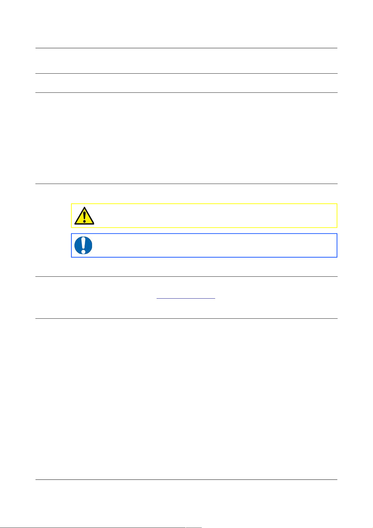
2.4 Typical Acquisition Modules
Stand-alone CMG-EAM
Stand-alone CMG-EAM
Cylindrical DAS
24 Channel DAS
CMG-NAM
MAN-EAM-0003 13 Issue E - February 2014
Page 14

Acquisition Modules and Platinum Firmware Equipment Overview
Integrated instruments (seismometer or accelerometer, digitiser and EAM)
2.5 Ports
This section lists the ports (external connectors) found on Platinum systems.
Not all ports listed in this section are available on all devices. A typical NAM,
for example, only has power and Ethernet ports while the CMG-5TCDE
integrated instruments have Data, GPS, Ethernet, GPIO and USB.
2.5.1 Ports A, B, C...
The 10-pin data input ports accept serial data from digitisers for processing by
an acquisition module. They can also be used for other functions, as listed in
the description of the Power/Data port, below.
2.5.2 SENSOR ports
CMG-DAS units have one or more 26-pin connectors for attaching analogue
instruments. They provide power and control signals to the instruments and
accept analogue data from the sensors.
The number of input connectors depends on the model of the digitiser.
2.5.3 Ethernet
The 6-pin Ethernet port is a 10BASE-T /100BASE-TX Ethernet connection,
referred to as eth0 within the user interface. The supplied cable supports
connection to a hub, switch or router. If direct connection to a PC or laptop is
required, an optional cross-over cable can be ordered.
MAN-EAM-0003 14 Issue E - February 2014
Note: Refer to section 16.5 on page 273 for information on
connector pin-outs.
Page 15

Acquisition Modules and Platinum Firmware Equipment Overview
2.5.4 GPIO
The 12-pin GPIO (General Purpose Input/Output) port fulfils three functions:
• It provides a serial console to the EAM, which can be used for
monitoring, configuration and control. This is permanently configured
to run at 38,400 baud;
• It provides USB access from a PC or laptop to the internal FLASH
storage for data collection (use of this feature is described in section
11.3.3 on page 161); and
• It provides a number of tri-state lines which can be used to control or
monitor external equipment. One application is as tamper detection
lines, which can be connected to external switches and monitors as
part of a secure installation.
2.5.5 USB
The 6-pin USB port allows connection of an external USB storage device for
data collection. It is also possible to perform firmware upgrades using this
port in situations where internet access is not available – see section 5.3.3 on
page 59 for details.
2.5.6 GPS
The 10-pin GPS port allows connection of a GSL GPS receiver for use as a
synchronisation source for time-stamping seismic data.
2.5.7 Power/Data
The 10-pin Power/Data Out port is a power input and also a general-purpose
serial port which can be used for GCF output (suitable for serial connection to
Scream), PPP network connections, inbound GCF (from a digital instrument,
for example), NMEA functions, TCP serial conversion, a modem answering
service or as a recorder to store and forward data from any instrument with a
serial output.
2.5.8 POWER
The 4-pin Power port, where fitted, is an alternative power input. It can be
used as a permanent power input in situations where the Power/Data port is
only used occassionally.
2.6 Typical Applications
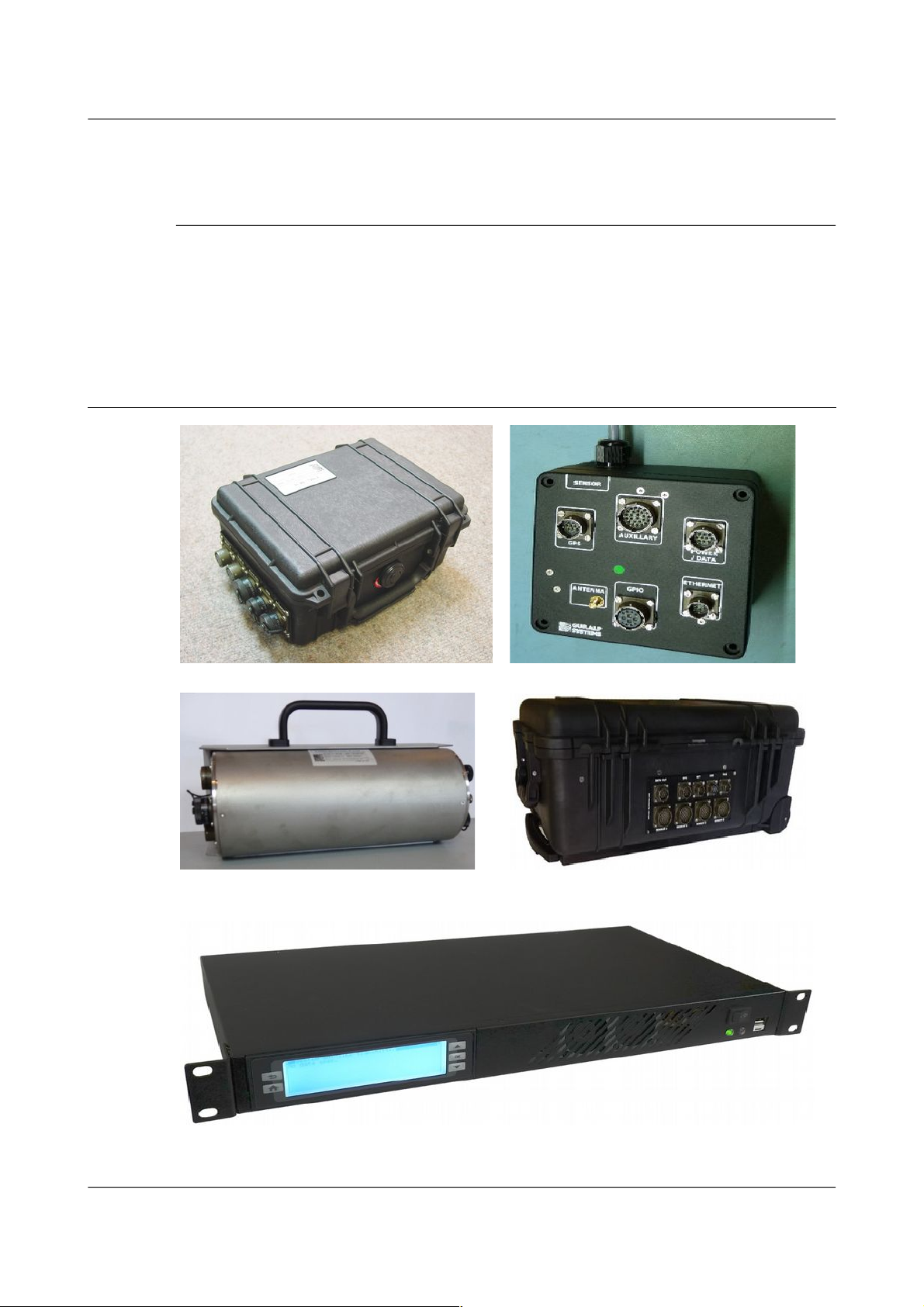
2.6.1 Autonomous remote data-logger
In this application, depicted below, a CMG-EAM is used to collect data from a
digital instrument (or analogue instrument and digitiser) and store it on its
MAN-EAM-0003 15 Issue E - February 2014
Page 16
Acquisition Modules and Platinum Firmware Equipment Overview
hard drive. The low power consumption and high storage capacity of the
CMG-EAM makes it ideal for this purpose.
Where appropriate, the battery supply can be augmented with a solar panel.
The CMG-EAM is capable of interfacing with and monitoring many types of
solar charge controller.
If it is desired to contact an acquisition module for monitoring or urgent data
download purposes, the unit can be fitted with a GPRS or satellite modem,
allowing remote connectivity.
2.6.2 Protocol Converter
An acquisition module can be deployed as a protocol converter: the wide
variety of output formats and connectivity options make it ideal for this
application. In the illustration below, a digital instrument's GCF output is
retransmitted as SEEDLink data over Ethernet.
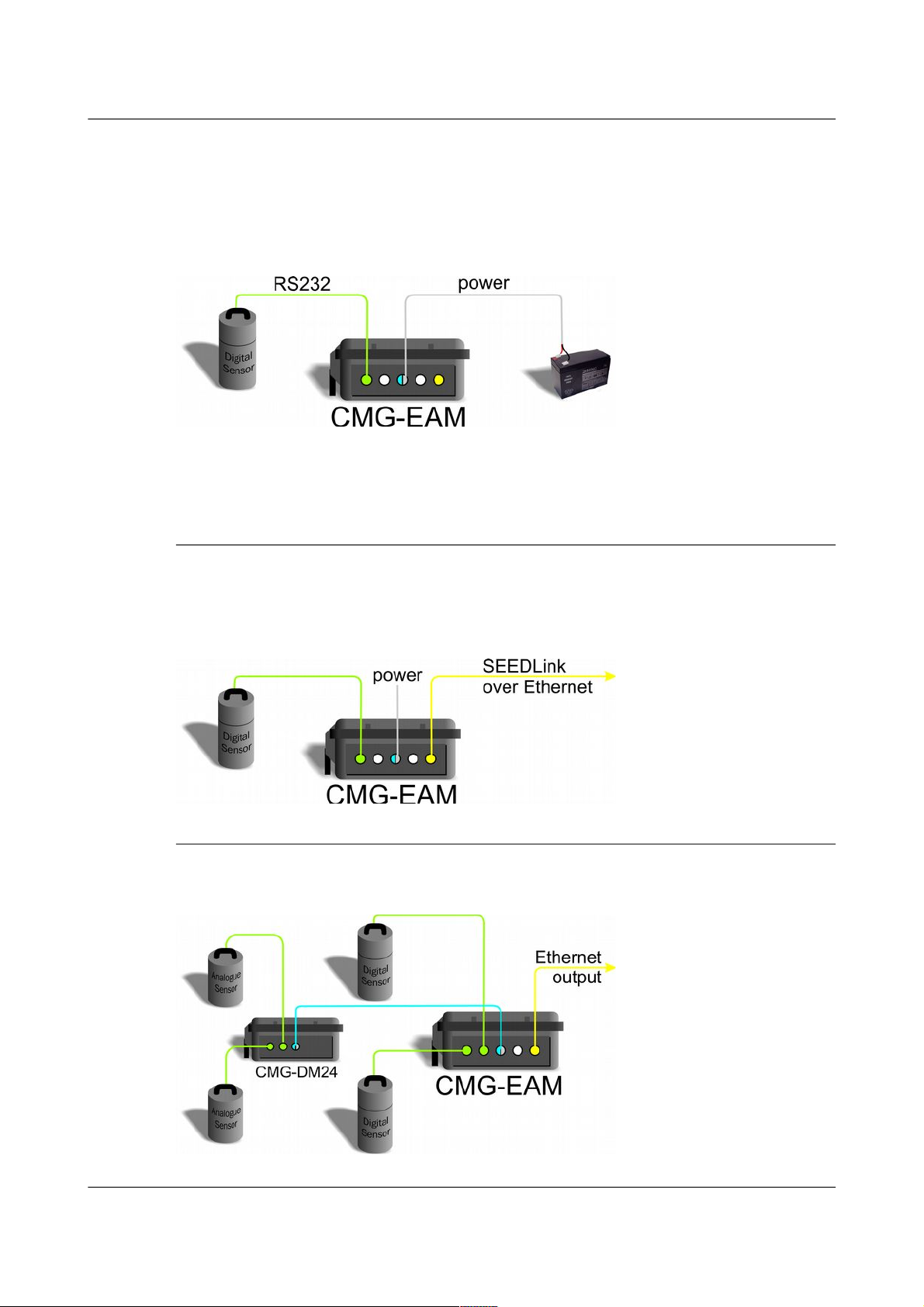
2.6.3 Array Concentrator
The acquisition module can combine the data from many instruments in an
array and retransmit them over a single link (serial or network).
MAN-EAM-0003 16 Issue E - February 2014
Page 17
Acquisition Modules and Platinum Firmware Equipment Overview
If the output link is over a network, all external serial ports of a standard
CMG-EAM (including the “DATA OUT” port) are available for connection to
digitisers or digital instruments, allowing up to eighteen channels to be
aggregated. An arbitrary number of CMG-EAMs may be chained together,
allowing for even more extensive arrangements.
2.6.4 PPP Networking
A serial output from the CMG-EAM can be used for point-to-point protocol
(PPP) networking. This protocol allows full internet access to the device over
a serial link. Operators can access the web page of the acquisition module for
configuration and monitoring. If other Ethernet devices are present at the
deployment site, the CMG-EAM can function as a router, passing their traffic
over the PPP link. The output from other serial devices can also be passed
over the PPP link by use of the built-in serial-to-TCP converter (see section 7.8
on page 97 for details).
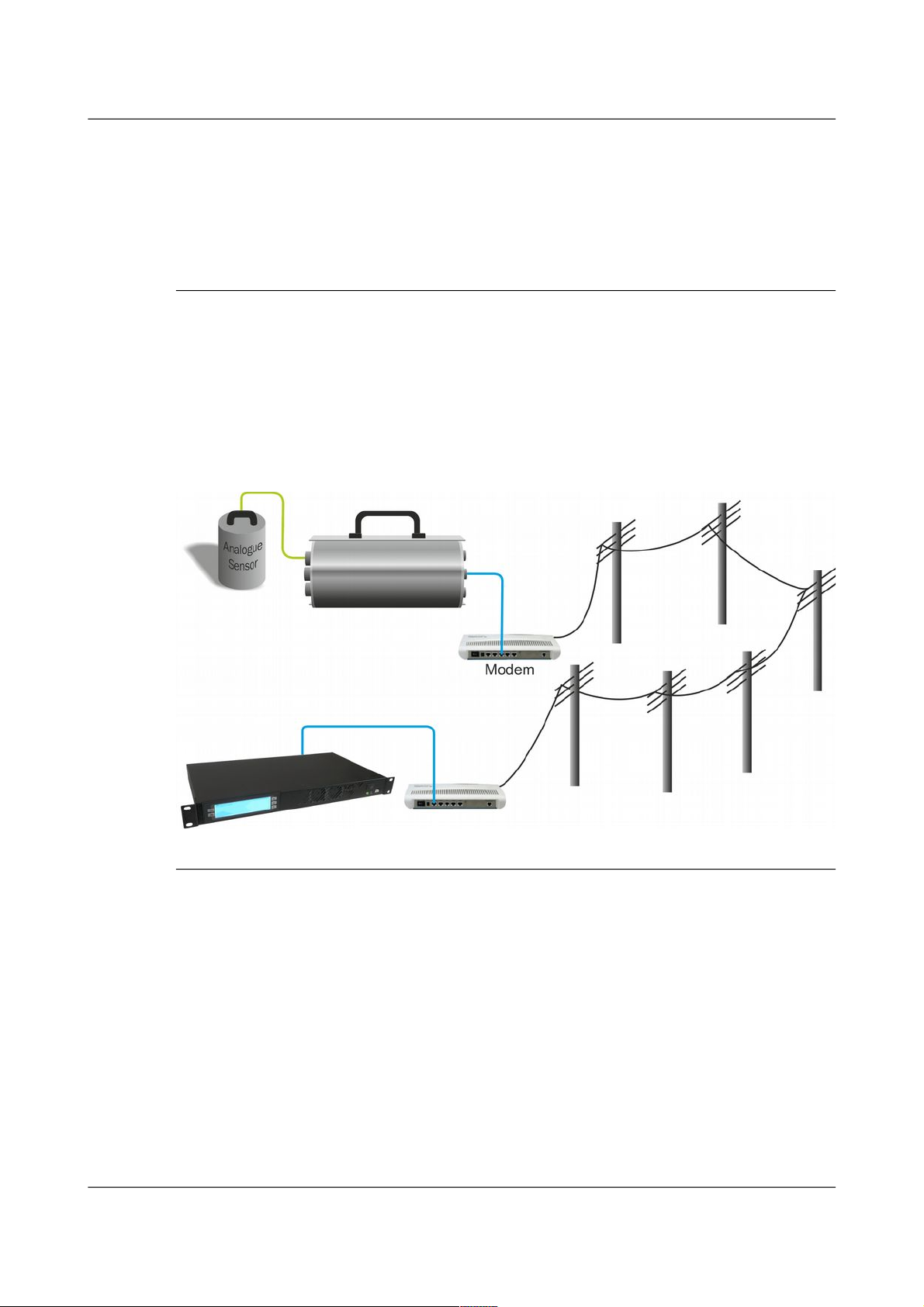
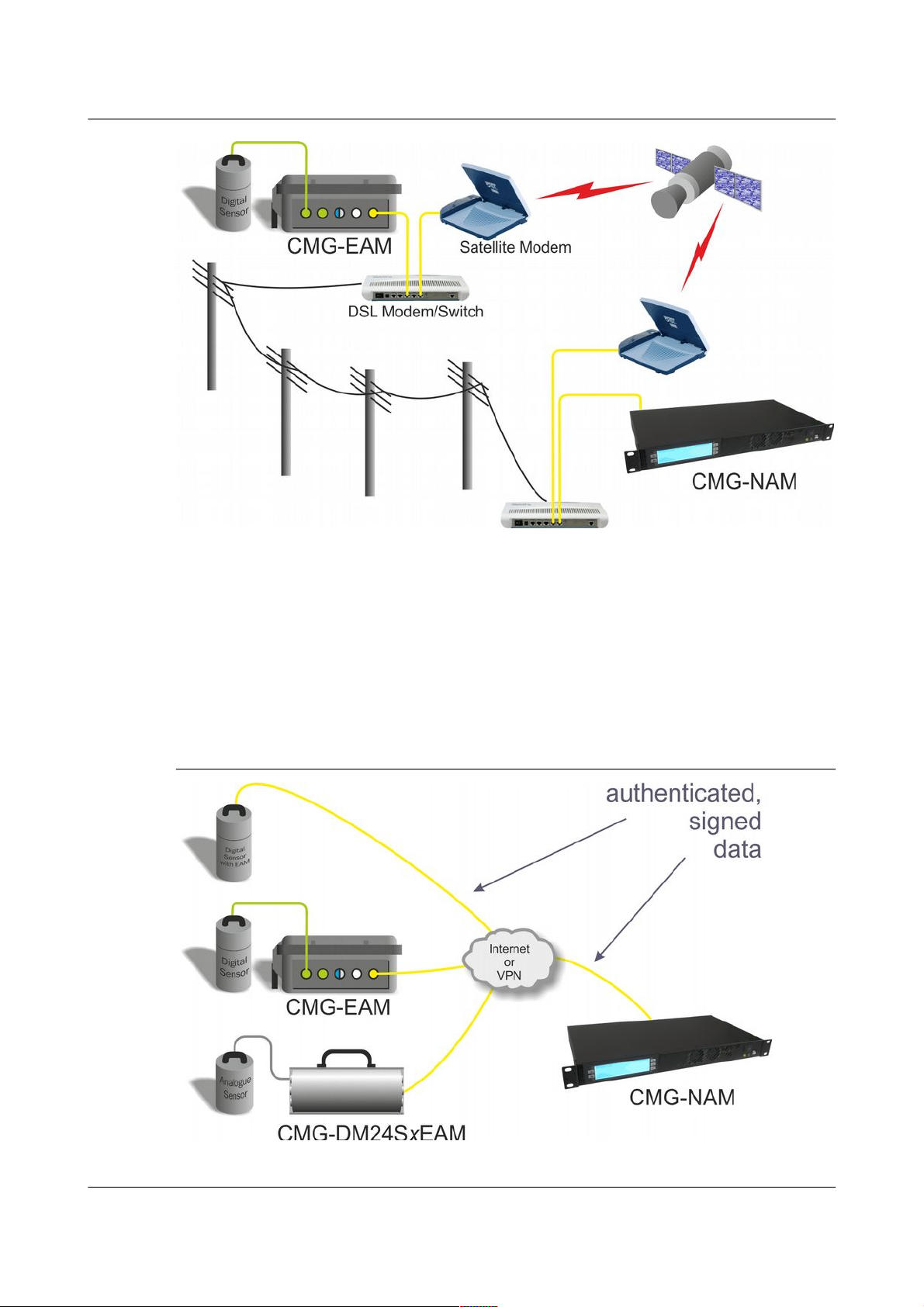
2.6.5 Resilient Networking
Platinum firmware includes a number of ways to implement network
resilience. For example, the GSTM protocol (for communication between
Platinum units) allows data to be routed over a low-cost but unreliable DSL
network with automatic switch-over to a higher-cost satellite link only when
the DSL network is unavailable. The failed link is regularly re-tried and,
when communication is re-established, the data are re-routed back to the
lower cost link.
The CMG-NAM acquires data from Scream servers (e.g. CMG-6TD or
CMG-3ESPCDE) and the data are stored locally on an optional RAID disk
array with up to 2 TB capacity.
MAN-EAM-0003 17 Issue E - February 2014
Page 18
Acquisition Modules and Platinum Firmware Equipment Overview
The CMG-NAM can also act as a data server to remote clients supporting GCF
(SCREAM server), EARTHWORM (via scream2ew), ANTELOPE (via
Guralp2orb), CD1.0/CD1.1 and SEEDLINK.
It is also possible to use data filtering (by channel name and/or sample rate) in
such a way that, should it become necessary to use the higher-cost link, only
high priority data (e.g. samples resulting from an activated trigger) are sent
across this link while lower priority data are enqueued until the low-cost link
becomes available again.
2.6.6 CD1.1 Networking
MAN-EAM-0003 18 Issue E - February 2014
Page 19

Acquisition Modules and Platinum Firmware Equipment Overview
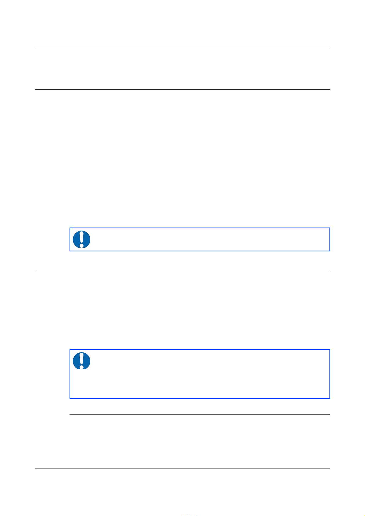
Platinum firmware has support for CD1.1 frame generation and forwarding
with strong authentication provided by an optional embedded Spyrus
hardware encryption device, allowing CMG-EAMs and CMG-NAMs to form
the basis of a secure CD1.1 network.
Data transmitted in CD1.1 format use strong authentication and digital
signatures to ensure that the received data are exactly those transmitted: i.e.
that they have not been tampered with during transmission.
Platinum firmware contains many facilities to support CD1.1. These are
documented in a separate manual, MAN-EAM-1100, which is available on
request from support@guralp.com.
MAN-EAM-0003 19 Issue E - February 2014
Page 20
Acquisition Modules and Platinum Firmware Initial set-up
3 Initial set-up
3.1 Introduction
All acquisition modules except the CMG-NAM can be configured and
monitored either over an Ethernet network or via a serial (RS232) line and are
provided with at least one network and one serial port. Because the
CMG-NAM is designed for use in a data centre, it only has a network port.
The actual number of network or serial ports is dependant on the exact model
of the acquisition module. CMG-EAMs in peli-cases are supplied with a
dedicated console connector located under the lid.
If using a network, the acquisition module can be accessed using a web
browser or, in character mode, using ssh. Instructions for connecting to the
network port are given in section 3.2 on page 20.
If you prefer to use serial communications, the module can be accessed using
a terminal emulator. Instructions for connecting via the serial port are given
in section 3.3 on page 30.
3.2 Connecting to the network port
To use the network port, you must first set up a network address. Some
networks need manual configuration (normally referred to as “static”
addressing); others use the Dynamic Host Configuration Protocol (DHCP) to
allow a DHCP server to automatically assign network addresses. If no DHCP
server is present, many systems will fall back to a randomly-generated
“link-local” address (known by Microsoft as Automatic Private IP Addressing,
or APIPA). Before you can access an acquisition modules over a network, you
must set (for static addresses) or discover (if you use DHCP) its IP address.
3.2.1 DHCP-assigned addresses
Acquisition modules are supplied configured for DHCP. If your network uses
DHCP to assign addresses, simply connect the acquisition module to the
network and wait a few minutes for the process to complete. Your network
administrator should then be able to tell you the address that has been
MAN-EAM-0003 20 Issue E - February 2014
Note: We recommend use of the web interface over a network for
general configuration and operation.
Note: If you are setting up a unit in the laboratory for subsequent
deployment in the field, you can set up the final network address
using the web interface and over-ride it with a temporary, static
network address using the command line. The web-configured
address will take effect when the unit is next rebooted.
Page 21

Acquisition Modules and Platinum Firmware Initial set-up
assigned to the acquisition module. If your module has an LCD status display
(CMG-NAMs and some integrated instruments), the assigned address will be
displayed in it. The LCD display shows lots of information so you may have
to wait a short time until the IP address scrolls into view.
When using DHCP, it is recommended that the DHCP administrator allocates
a fixed IP address to the acquisition module's MAC address in order to avoid
unexpected address changes. The MAC address is displayed by the ip
command – in the example in section 3.2.1.1 on page 21, it is
00:50:c2:40:54:75.
If you cannot learn the IP address in this way, there are three methods
available to discover which address has been allocated.
3.2.1.1 Address discovery – serial connection
You can connect via a serial port (as described in section 3.3 on page 30) and
issue the ip command:
eam999 ~ # ip addr show eth0
2: eth0: <BROADCAST,MULTICAST,UP,LOWER_UP> mtu 1500 qdisc
pfifo_fast qlen 1000
link/ether 00:50:c2:40:54:75 brd ff:ff:ff:ff:ff:ff
inet 192.168.0.101/24 brd 192.168.1.255 scope global eth0
inet6 fe80:250:c2ff:fe40:5475/64 scope link
valid_lft forever preferred_lft forever
eam999 ~ #
The key things to look for here are the adapter status and the IP address. The
first line of the output should contain the word UP, confirming that the
adaptor has been enabled. The IP address that has been assigned is shown on
the line beginning inet - in this case, it is 192.168.0.101 (with a netmask
of 24 bits indicated by /24).
3.2.1.2 Address discovery – Scream's “Detect servers” tool
Start with the EAM turned off. Then, from Scream's “Network control”
window, select the “My Client” tab. Right-click in the server list-box and
select “Detect servers...” - Scream will then start monitoring DHCP traffic on
the local network. Power up the EAM and allow it a minute to boot. When
Scream notices a DHCP negotiation with an appropriate MAC address, it will
display the allocated IP address in the window. You can add the EAM to
Scream's list of servers by clicking the appropriate button.
MAN-EAM-0003 21 Issue E - February 2014
Note: With an IP version 6 network, the IP address will be on a line
beginning inet6. In practice, most networks today are still IPv4,
as in the above example.
Page 22
Acquisition Modules and Platinum Firmware Initial set-up
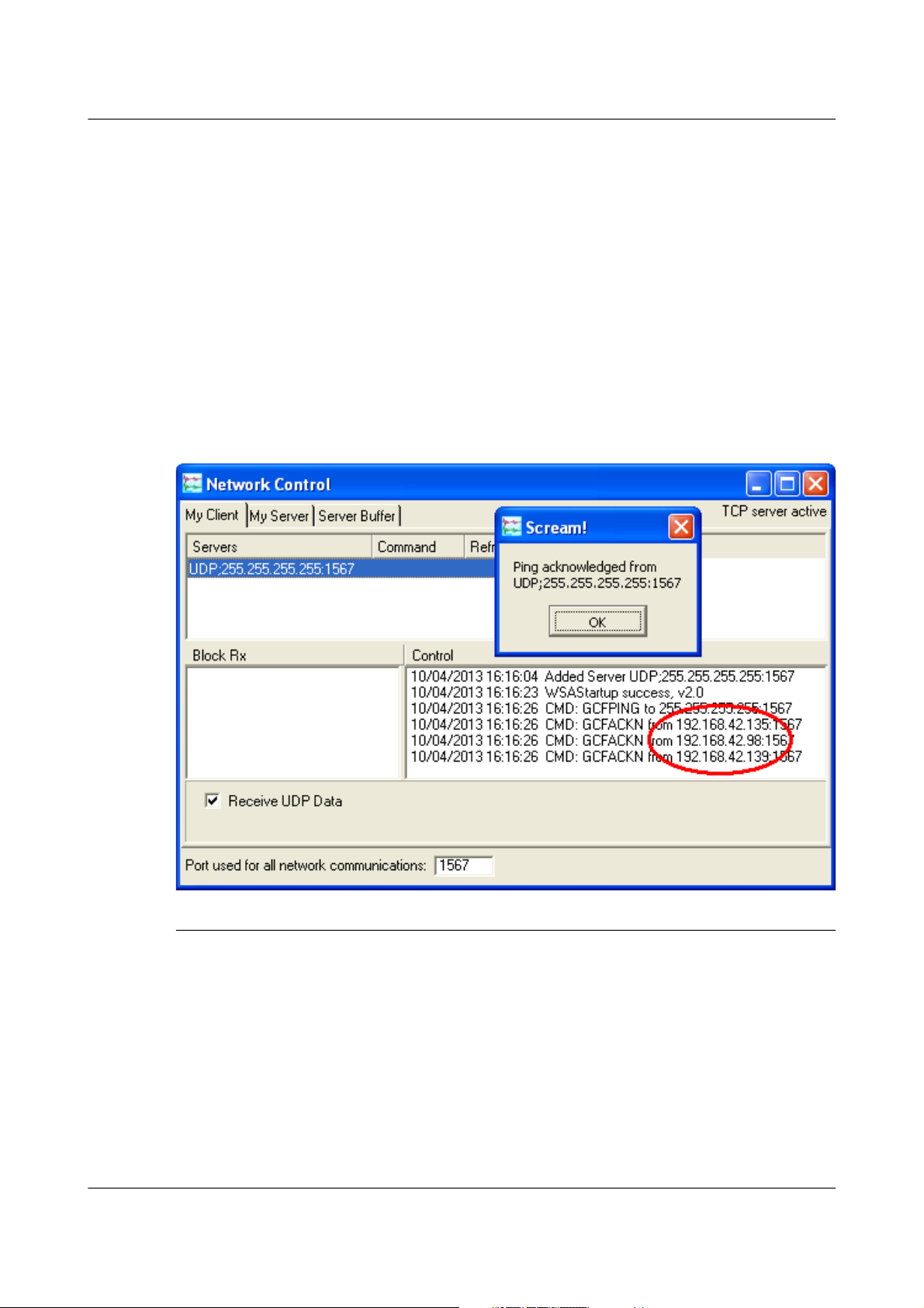
3.2.1.3 Address discovery – GCFPing
Scream's “GCFPing” feature sends a specially formatted broadcast packet to all
hosts on the local network. Any GCF servers that see this packet should
respond with a GCF acknowledgement packet (GCFACKN). Scream displays
the IP addresses associated with all acknowledgement packets that it receives.
To use this feature, add a new UDP server with an IP address of
255.255.255.255. Right-click the server and select GCFPING from the context
menu. A window will appear as shown below if the ping packet is
acknowledged. In the control pane (at the bottom right of the main window),
a GCFACKN line will be printed for every address that responded to the
GCFPING. In the example below, you can see responses from 192.168.42.135,
192.168.42.98 and 192.168.42.139. These are the addresses of all GCF servers
listening on port 1567 on the local network.
3.2.2 Link-local addresses
Many systems, when configured for DHCP, will generate a random address if
no DHCP server is present. This is known as a “link-local” or APIPA address.
For IPv4 networks, it will be in the range 196.254.0.0 to 196.254.255.254 (i.e.
on the 196.254.0.0/16 network). For IPv6 networks, it will be in the fe80::/10
network. The random, host-specific part of the address is derived from the
(unique) MAC address, so there are unlikely to be conflicts between addresses
of systems in networks with small or medium numbers of hosts.
This is useful when, for example, visiting a remote EAM: A laptop can be
plugged directly into the network port of the EAM (using a cross-over cable, if
MAN-EAM-0003 22 Issue E - February 2014
Page 23
Acquisition Modules and Platinum Firmware Initial set-up
necessary) and, provided both systems are set to use DHCP, both will assign
themselves addresses on the same network. If the laptop is running Scream,
you can add a server using the link-local network's broadcast address,
196.254.255.255, and start communicating immediately. If the address of the
acquisition device is required (for, say, web access), this can be read from
Scream's control window, or in the acknowledgement window resulting from
a GCFPING.
The acquisition device will search for a DHCP server every minute and,
should one become available, it will ask it for a new address.
3.2.3 Assigning a static IP address
If you wish to configure a static IP address, you must first connect to the
command line via a serial port. This process is described in section 3.3 on
page 30.
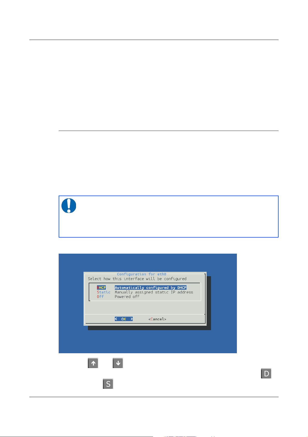
3.2.3.1 Assigning a static IP address using net-setup
Once logged in, issue the following command:
eam999 ~ # net-setup
The following screen is displayed:
Using the and keys (or, on some systems, the mouse), select whether
you wish to use DHCP or static addressing. You can, alternatively, key to
select DHCP or to select static addressing. Use the ENTER key to confirm
MAN-EAM-0003 23 Issue E - February 2014
Note: This command relies on the EAM understanding what type of
terminal emulator you are using. If the display is corrupted and not
usable, set the TERM variable (see section 4.3.1 on page 35), or
simply power-cycle the EAM and use the ip command (see section
3.2.3.2 on page 25) instead.
Page 24
Acquisition Modules and Platinum Firmware Initial set-up
your choice. If you do not wish to make a change, use the key to select
“Cancel” and then key ENTER to close the net-setup tool and return you to the
command prompt.
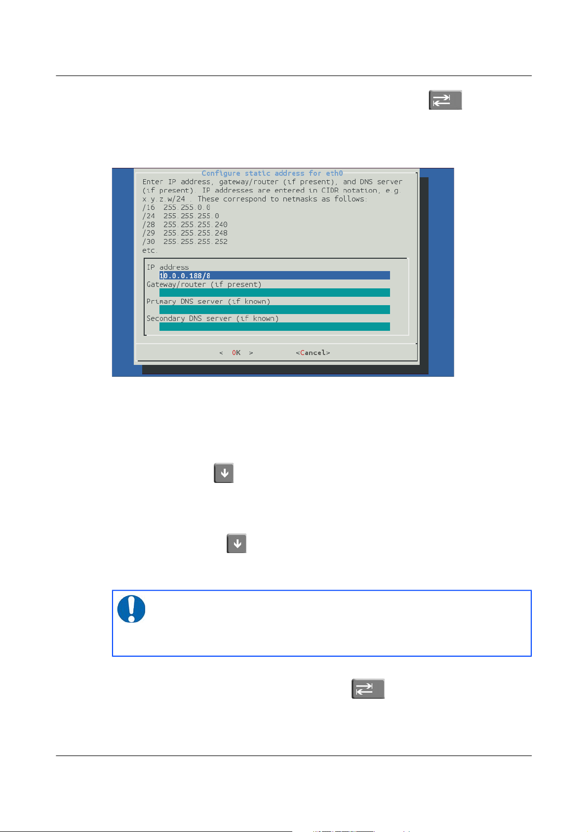
If you select static addressing, the following screen is displayed:
The IP address field must be populated with a valid IP address in CIDR
notation. If you know the netmask but not the corresponding CIDR notation,
use the information on screen as a guide or search the web for an on-line
converter.
If your network has a router which acts as a gateway to the Internet or to other
networks, use the key (or, on some systems, the mouse) to move to the
“Gateway/router” field and enter the address of the gateway in standard,
dotted-quad notation (i.e. 10.0.0.1).
If your network has a DNS (domain-name service) server, sometimes called a
name-server, use the key (or, on some systems, the mouse) to move to the
“Primary DNS server” field and enter the address of the name-server in
standard, dotted-quad notation (i.e. 10.0.0.5).
Use the ENTER key to confirm your choice and reconfigure the network. If
you do not wish to make a change, use the key to select “Cancel” and
then key ENTER to close the net-setup tool and return you to the command
prompt.
MAN-EAM-0003 24 Issue E - February 2014
Note: If your network is connected to the Internet but you do not
know the name of your DNS server, ask your Internet Service
Provider for the correct address to use or enter 8.8.8.8, which is a
free, public DNS server operated by Google Inc.
Page 25
Acquisition Modules and Platinum Firmware Initial set-up
3.2.3.2 Assigning a static IP address using the ip command
The ip command is an alternative to net-setup. You may wish to use it if
• you want to configure a temporary address without updating the
configuration files
• you cannot use the net-setup utility for any reason
• you are very familiar with the linux command line
Log in as normal and then issue the following command:
eam999 ~ # ip addr add 192.168.0.1/24 dev eth0
replacing the example IP address (192.168.0.1/24 in the example above)
with the required value. It must be specified in CIDR format, where the actual
address is followed by the number of bits of the network mask. The above
example uses 192.168.0.1 with a netmask of 255.255.255.0 (24 bits of network
address). A PC connected to this network could communicate with the
acquisition module if it was configured to use an IP address of (for example)
192.168.0.2 with a matching netmask of 255.255.255.0.
If you wish to connect to the acquisition module from a PC, they must either
both be on the same physical network and have the same network address
(usually the first three numbers of the IP address) or be able to connect to
each other via routers.
In the latter case, you will need to tell the acquisition module the address of
its default router (also known as the gateway). Issue the command:
eam999 ~ # ip route add default via 192.168.0.254
substituting the address of your network's default router in place of the
example address (192.168.0.254) shown.
If you wish to be able to access your acquisition module across the Internet,
perform firmware upgrades or access GSL remote support, you will also need
to configure a default router as described in the preceding paragraph.
MAN-EAM-0003 25 Issue E - February 2014
Note: IP addresses assigned using this method will be lost if the
unit is rebooted. To permanently assign an IP address, use
net-setup (see section 3.2.3.1 on page 23), the web interface
(section 7.1 on page 70) or gconfig (section 7.1 on page 70).
Note: Both the static IP address and any route configured in this
way are temporary and will persist only until the acquisition
module is rebooted or powered off. Refer to section 7.1 on page 70
for information about configuring permanent static IP addresses and
routes.
Page 26

Acquisition Modules and Platinum Firmware Initial set-up
If you wish your acquisition module to initiate connections with remote
systems across the Internet, or to be able to access firmware upgrades, you
need to configure a DNS server (also known as a name-server). If you do not
know the address of your DNS server, your Internet Service Provider (ISP)
will be able to tell you. You can also use 8.8.8.8, which is a free, public DNS
server operated by Google Inc. Enter the command
eam999 ~ # echo "nameserver 8.8.8.8" >> /etc/resolv.conf
substituting the address of the required DNS server in place of the example
address (8.8.8.8) shown in the example above.
3.2.4 Connecting to the web interface
The Platinum firmware on all acquisition modules provides a web interface
for configuration and control of the module and connected equipment. While
there are other methods of connecting to the modules, the web interface is
recommended.
Once the IP address of the acquisition module has been set or determined,
enter the it into the address bar of a web browser to connect to the module's
web interface . The examples below are for an EAM address entered into
Firefox and Internet Explorer:
On versions of Platinum from release 10,000, the web interface will initially
show a status display and a brief menu. There is an option to log in on that
menu. Click on the link and enter the default user-name of root and
password of rootme.
If you are connecting to the acquisition module over a network that you
consider insecure (such as the internet), it is recommended that you use the
HTTPS (secure HTTP) protocol, which uses TLS to encrypt the link. Simply
change the http:// prefix to https:// in the browser's address bar. Most
browsers will complain that the certificate cannot be verified: This is not a
problem: simply press the “accept” button to proceed. The link will then be
encrypted and nobody will be able to “sniff the wire” in an attempt to discover
passwords and other data.
Once connected and logged in, you will be presented with the main summary
screen and a much larger menu. The summary screen contains general
information about the status and health of the connected modules and
equipment.
The exact contents and layout of this screen will vary depending on the
configuration of both the acquisition module and of any attached devices.
See section 4on page 33 for information on using the web interface.
MAN-EAM-0003 26 Issue E - February 2014
Page 27

Acquisition Modules and Platinum Firmware Initial set-up
3.2.4.1 Connection trouble-shooting
If the browser fails to connect, the most likely explanation is that the machine
running the browser does not have working network communications to and
from the acquisition module. This can be verified by “pinging” the IP
address of the browser from the command line of the acquisition module:
eam999 ~ # ping -c3 192.168.0.2
PING 192.168.0.2 (192.168.0.2): 56 data bytes
64 bytes from 192.168.0.2: seq=0 ttl=63 time=2.284 ms
64 bytes from 192.168.0.2: seq=1 ttl=63 time=1.129 ms
64 bytes from 192.168.0.2: seq=2 ttl=63 time=1.944 ms
--- 192.168.42.1 ping statistics --3 packets transmitted, 3 packets received, 0% packet loss
round-trip min/avg/max = 1.129/1.785/2.284 ms
eam999 ~ #
To resolve this class of problem, ensure that the cables are functioning (which
can be verified by checking the diagnostic lights on most switches/hubs) and
double-check that the PC and acquisition module are on the same subnet
(which means the CIDR suffices must match and the first sections of the IP
addresses – as defined by the CIDR suffices - must also match). The website
http://en.wikipedia.org/wiki/IP_address has some useful information for those
for whom sub-networking is unfamiliar.
3.2.5 Connecting to the command line using SSH
SSH (Secure SHell) is the most flexible way to control an acquisition module,
but it is less friendly than using the web interface. It is possible to configure
more advanced operations using SSH but the majority of control and
configuration tasks can be achieved most easily through the web interface.
SSH is shipped as standard with most Linux distributions and is available for
Windows as part of the free terminal emulation package PuTTY, which is
available from http://www.chiark.greenend.org.uk/~sgtatham/putty/
3.2.5.1 SSH connections using the ssh program
To use SSH, you must know or discover the IP address of the unit, as
described in the previous section. Once you have the IP address, issue the
SSH command on the PC you are using:
mypc$ ssh root@192.168.0.1
Replace 192.168.0.1 with the IP address of the acquisition module.
The first time you use SSH to connect to a host, you will be asked to verify the
“host key”. This is normal but, if you are ever asked this again, it means that
either the host key of the acquisition module has changed – perhaps because
of a firmware upgrade – or there is a network address conflict or, worse, a
security problem on your network.
MAN-EAM-0003 27 Issue E - February 2014
Page 28

Acquisition Modules and Platinum Firmware Initial set-up
user@mypc:~$ ssh root@192.168.0.1
The authenticity of host '192.168.0.1 (192.168.0.1)' can't
be established.
RSA key fingerprint is
62:a6:70:29:d4:1a:db:5a:75:6e:96:13:54:f5:a9:d9.
Are you sure you want to continue connecting (yes/no)? yes
Warning: Permanently added '192.168.0.1' (RSA) to the list
of known hosts.
root@192.168.0.1's password:
eam999 ~ #
You will be prompted for a password; the default password is rootme. Note
that no characters will be echoed to the screen as you type the password.
Once connected, you will be presented with a shell prompt which is ready to
accept commands.
When you are finished with your SSH session and want to disconnect, enter
exit at the command line, or type + . There are a number of escape
sequences for controlling the session, all of which begin with a tilde (' ~') so, if
you need to send a tilde character to the acquisition module, type two tildes
consecutively. For more information, see the section on “Escape Characters”
in the manual at http://man - wiki.net/index.php/1:ssh
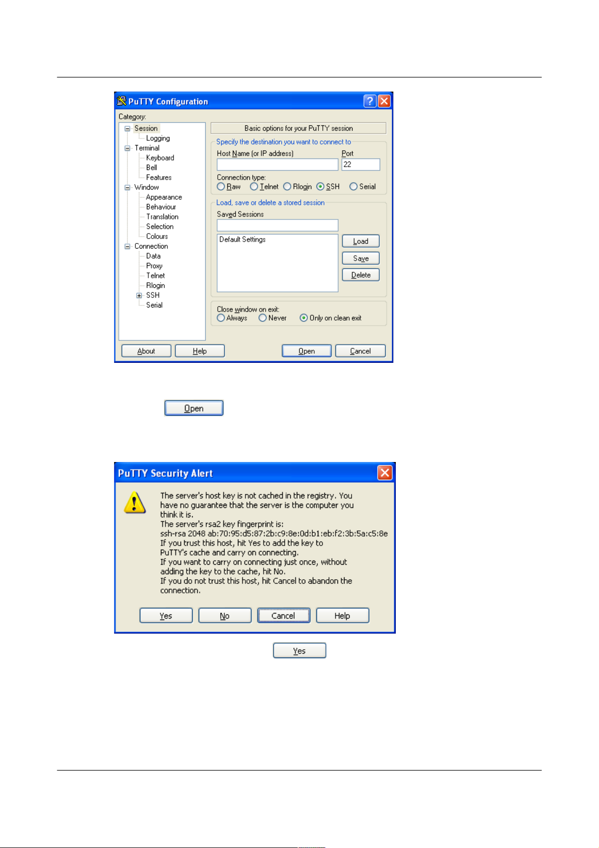
3.2.5.2 SSH connections using PuTTY
To use PuTTY, you must first know or discover the IP address of the unit, as
described in the previous sections. Once you have the IP address, start
PuTTY by choosing it from the “Start” menu or double-clicking on its icon.
You will be presented with the following screen:
MAN-EAM-0003 28 Issue E - February 2014
Note: If you plan to use ssh regularly to communicate with a
acquisition module, you can configure the system to bypass the
password prompt when logging in from a list of pre-authorised
computer/user combinations. This involves generating a unique
key-pair (for the user and PC which will access the acquisition
module) and then copying the public half of the key-pair to the
acquisition module. This can be more secure than passwords and is
fully documented at http://suso.org/docs/shell/ssh.sdf. For details
about uploading your keys to the CMG-EAM, see section 7.6 on
page 90.
Page 29
Acquisition Modules and Platinum Firmware Initial set-up
Enter the IP address of the acquisition module into the Host Name (or IP
address) field, check that SSH is selected as the Connection type and then
click the button.
The first time you use SSH to connect to a host, you will be asked to verify the
“host key”:
This is normal (simply click to dismiss the dialogue) but, if you are
ever asked this again, it means that either the host key of the acquisition
module has changed – perhaps because of a firmware upgrade – or there is a
network address conflict or, worse, a security problem on your network.
You will now be prompted for a login name: the default is root. Type this at
the prompt and press the ENTER key. You will next be prompted for a
MAN-EAM-0003 29 Issue E - February 2014
Page 30
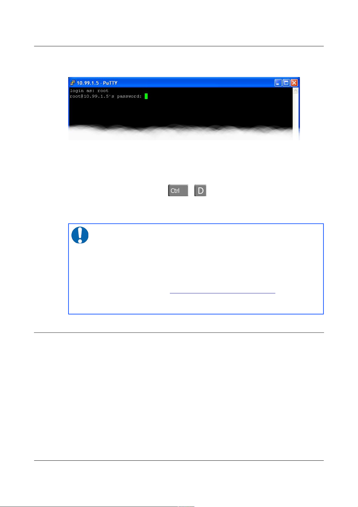
Acquisition Modules and Platinum Firmware Initial set-up
password; the default password is rootme. Note that no characters will be
echoed to the screen as you type the password.
Once connected, you will be presented with a shell prompt which is ready to
accept commands. The shell prompt contains the serial number of the
acquisition module.
When you are finished with your SSH session and want to disconnect, type
“exit” at the command line, or + .
PuTTY allows you to save multiple sessions, along with a default login
identity and screen colours for each. See the PuTTY manual for more details.
3.3 Connecting to the Serial Port
A number of acquisition modules have dedicated a 9-pin 'D' console port
connector located under its lid. It can be connected via a serial (RS232) cable
to a PC. See section 16.5.5 on page 277 for the pin-out.
Some acquisition modules without a dedicated console port connector are
supplied with 'Y' cables that connect to the DATA OUT port, your PC and a
power supply.
Acquisition modules with a GPIO connector are provided with a blue serial
cable, terminating in a female DE9 connector. This gives access to the
module's console.
Once you have connected the serial cable, you can run either Scream or a
terminal emulator to interact with the acquisition module.
MAN-EAM-0003 30 Issue E - February 2014
Note: If you plan to use ssh regularly to communicate with a
acquisition module, you can configure the system to bypass the
password prompt when logging in from a list of pre-authorised
computer/user combinations. This involves generating a unique
key-pair (for the user and PC which will access the acquisition
module) and then copying the public half of the key-pair to the
acquisition module. This can be more secure than passwords and is
fully documented at http://suso.org/docs/shell/ssh.sdf. For details
about uploading your keys to the CMG-EAM, see section 7.6 on
page 90.
Page 31

Acquisition Modules and Platinum Firmware Initial set-up
3.3.1 Using Scream
Select Terminal... from the File menu. A window will open, from where
you can select the correct serial port:
Set the Baud Rate to 38400, as shown, and ,once the acquisition module and
computer are communicating properly, an emulation window will open and
you will see the Login: prompt. If it does not appear immediately, press the
ENTER key a few times.
3.3.2 Using a terminal Emulator
You are free to use whatever terminal emulation software you wish. Common
choices are applications such as minicom on Linux or PuTTY on Microsoft
Windows. See section 16.2 on page 262 for more information.
Configure your emulation software to use the correct serial port. Set the line
speed (Baud rate) to 38,400 and the communication parameters to eight data
bits, no parity bits and one stop bit. This combination is commonly referred to
as “8-N-1”. Turn off all hardware flow control (RTS/CTS and/or DSR/DTR
should not be used). Turn off all software flow control (XON/XOFF should
not be used).
Once the emulator is connected, you will see a Login: prompt. If it does not
appear immediately, press the ENTER key a few times.
MAN-EAM-0003 31 Issue E - February 2014
Note: If a terminal session has just been closed, it can take up to ten
seconds for a new session to start.
Note: If a terminal session has just been closed, it can take up to ten
seconds for a new session to start.
Page 32

Acquisition Modules and Platinum Firmware Initial set-up
3.3.3 Logging in
Acquisition modules are shipped with a default user-name of root and
password of rootme. (Additional users with controlled capabilities can be
added if required).
Enter the user name and password. Note that nothing will display on the
screen when typing the password. You will then be presented with a shell
prompt, which will accept commands as shown in the image below:
eam999 login: root
Password:
eam999 ~ #
The output may vary slightly due to the configuration of the unit. In
particular, the acquisition module name, as displayed in the prompt (eam999
in this example), will be different.
MAN-EAM-0003 32 Issue E - February 2014
Page 33

Acquisition Modules and Platinum Firmware Platinum Overview
4 Platinum Overview
4.1 Introduction
All key acquisition module configuration and control tasks can be carried out
either from the web interface or from the command line.
The web interface presents some additional options not available from the
command line. Some of these are merely short-cuts into the main
configuration system while others offer additional monitoring and diagnostic
facilities. Configuration of attached digitisers can be carried out using the
web interface but not from the command line (although access to the
digitiser's command line is available).
The command-line interface also supports a number of advanced facilities
which are not available via the main configuration system: these are mostly
diagnostic tools which are not required for normal operation.
4.2 Using the web interface
The web interface is split into two frames:
The left-hand frame contains the system ID above a menu while the main
frame displays sub-menus, input forms and display screens.
4.2.1 Navigation aides
To help with navigation, the main frame displays a series of links indicating
the current position in the configuration-system hierarchy:
These links are commonly known as a “bread-crumb trail”. The “Home” link
will return the user to the system home page shown above.
MAN-EAM-0003 33 Issue E - February 2014
Page 34
Acquisition Modules and Platinum Firmware Platinum Overview
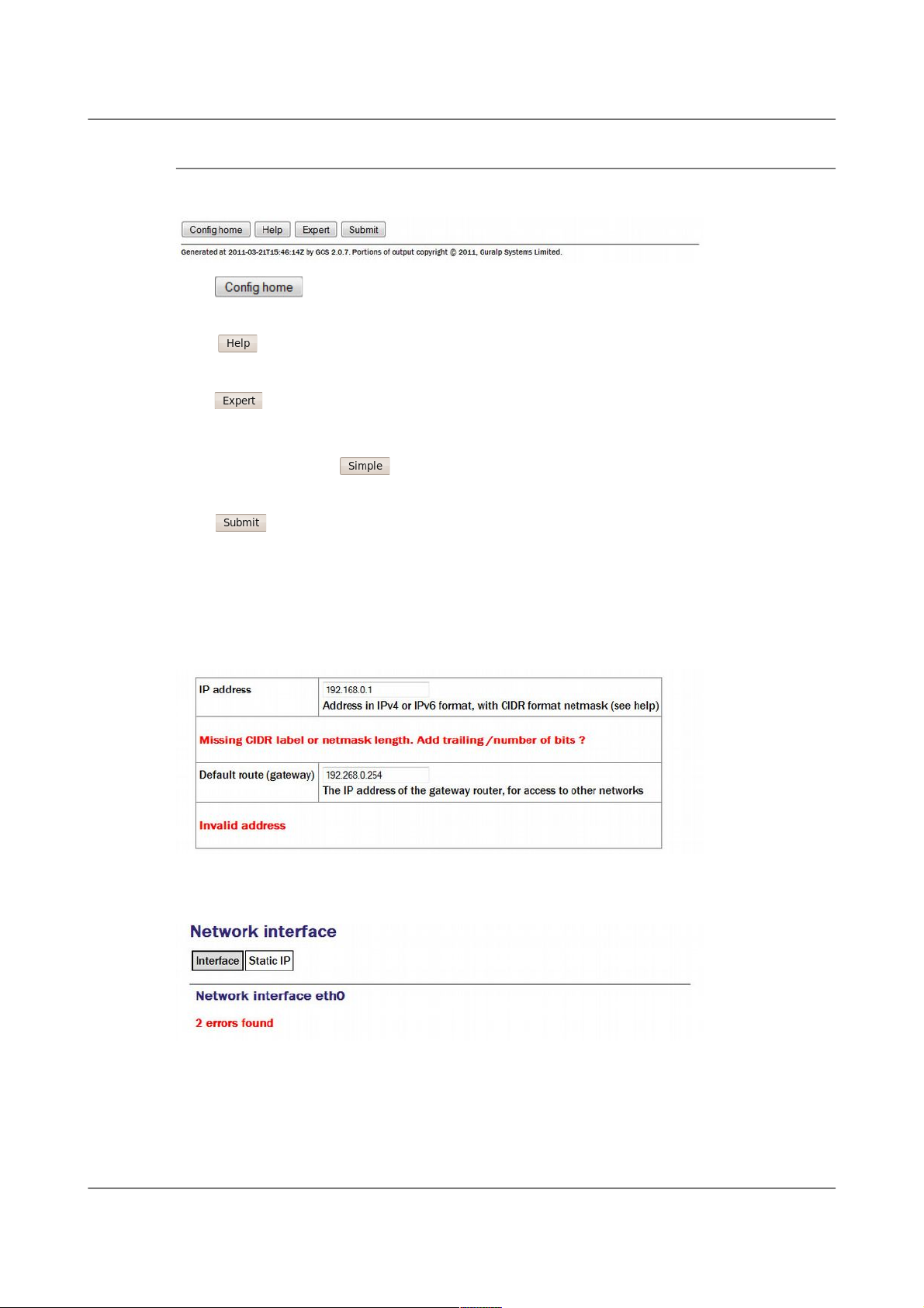
4.2.2 Display options and form submission
Many web forms display a series of buttons at the bottom of the form:
The button returns you to the configuration homepage. This page
can also be accessed using the All options link in the main menu.
The button displays on-line help in blue, interleaved with the form
fields.
The button changes the display mode to show extra form fields that do
not normally need to be changed. These 'expert' settings are all described in
the relevant section of the manual for that screen. When in expert mode, the
button changes to so that the display can be returned to the default
mode.
The button sends the updated settings to the acquisition modules. In
many cases, the changes are accepted immediately; some, however, require a
reboot of the modules or attached device.
User input to the forms is validated after submission. Where invalid
parameters have been detected, an error message is displayed in red below the
appropriate field:
On pages where there are tabbed pages, the number of errors is displayed on
the first tabbed screen:
Throughout the remainder of this manual, screen-shots of the configuration
system's web interface will normally omit the left-hand pane, as in the two
illustrations above.
MAN-EAM-0003 34 Issue E - February 2014
Page 35

Acquisition Modules and Platinum Firmware Platinum Overview
4.2.3 Navigation instructions in the manual
In this manual, instructions on how to reach a particular screen are displayed
like this:
Configuration → Interfaces → eth0 - Primary wired network interface
In this example, to reach the page indicated, scroll to the “Configuration”
section of the main menu then click on the “Interfaces” link". From the list
that appears in the main frame, click on the “eth0 - Primary wired network
interface” link.
In some cases there are two possible paths to a particular screen. Both are
shown in the manual.
4.3 Using the command-line configuration system
All of the configuration facilities available under the “All options” item (in the
main menu of the web interface) are also available from a text-based GUI tool
called gconfig (Güralp Configurator). This can be accessed either by using a
serial link or, over the network, by using ssh.
Connection via a serial link is discussed in section 3.3 on page 30 and
connecting over Ethernet is described in section 3.2 on page 20. The use of
ssh is covered in section 3.2.5 on page 27.
4.3.1 Using graphical interfaces from the command line
Some Platinum applications use a system called “ncurses”, which allows
graphical interfaces to be implemented on text-only terminals. This requires
the applications to know the type of terminal from which they are being
accessed. The terminal type is stored in an environment variable called TERM,
which is queried with the command
eam999 ~ # echo $TERM
vt100
eam999 ~ #
(note the use of the $ sign when accessing the value of this variable) and set
with the command
eam999 ~ #: export TERM=vt100
No spaces should be used around the '=' sign.
Platinum is aware of around thirty different terminal types and uses the
“terminfo” system to support them (so you can add your own types, if you
need). Files describing each terminal type are stored under the directory
(folder) /usr/share/terminfo in sub-directories named after the initial
letter of the terminal name.
Some settings for specific applications are given in the following table.
MAN-EAM-0003 35 Issue E - February 2014
Page 36

Acquisition Modules and Platinum Firmware Platinum Overview
Emulator in use TERM setting
ssh under Unix No action required - the ssh protocol sets the
TERM environment variable automatically.
PuTTY (in ssh mode)
under Windows
No action required - the ssh protocol sets the
TERM environment variable automatically.
PuTTY will default to xterm emulation, allowing
the mouse to be used within gconfig.
Minicom under Unix Minicom emulates a vt100-style terminal and
automatically maps the keystrokes and display
sequences for the actual terminal you are using,
so the default TERM setting of vt100 is correct.
HyperTerminal under
Windows
Using the File menu option “Settings”, ensure
that the terminal type is set to VT100.
HyperTerminal will then emulate a vt100 style
terminal, which will match the default
TERM=vt100 on the acquisition module.
Scream Scream versions before 4.5 did not support the
required screen-drawing control codes so an
upgrade to version 4.5 or later is recommended.
These settings will provide the best results for the listed applications. Note
that, when connecting with SSH from an xterm window, for example, use of
the mouse for menu navigation is supported.
4.3.2 Using gconfig
When you enter the gconfig command, the initial screen looks like this:
The gconfig interface can be navigated entirely using the keyboard but, if you
use xterm (or your terminal emulator supports an “xterm” mode) you can use
MAN-EAM-0003 36 Issue E - February 2014
Page 37

Acquisition Modules and Platinum Firmware Platinum Overview
your mouse to select menu items, input fields and items from drop-down
menus. The scroll-wheel is not currently supported, so you need to use the
keyboard to access second and subsequent pages of multi-page forms.
The gconfig interface displays menus and forms. The screen-shot above is an
example of a menu. The following table shows the navigation keys that are
available for use with menus:
Keystroke Used for...
, or
Cursor to next item
or
Cursor to previous item
Select item under cursor
or
Move to the next page of a multi-page menu
or
Move to the previous page of a multi-page menu
Go to the home menu or, if there already, exit
gconfig.
The four words enclosed in chevrons at the bottom of screen act as
push-buttons:
They are always present at the bottom of each gconfig screen, although they
change slightly according to the context. To invoke the action associated with
any of them, move the cursor to it and press .
In the example, all options other than are disabled and this is indicated
by the colour coding. If you select an item from a menu which leads to a
sub-menu, the option changes to and invoking it will then take
you back to the top-level menu.
Selecting a menu item will lead you either to another menu or to a form.
Forms are composed of text entry fields, check boxes or drop down menus (all
described below).
To move between fields, use the , or keys.
4.3.3 Text entry fields
Text-entry fields are those into which the operator can type textual
parameters. Text-entry fields are identified by surrounding braces: [ and ]
MAN-EAM-0003 37 Issue E - February 2014
Page 38

Acquisition Modules and Platinum Firmware Platinum Overview
To edit the contents of a text-entry field, move the cursor on the field and start
typing. Characters typed are always inserted at the current cursor position i.e.
existing characters are never over-typed. The whole field is shown with a
black background, as seen below, and the cursor is identifiable as a pale
block.
The and keys move the cursor within the field and the key
deletes characters to the left of the cursor.
4.3.4 Check-boxes
Check-boxes offer the operator a “yes/no” choice. Check-boxes are identified
by surrounding guillemots: '{' and '}'.
To change the setting of a check-box, move the cursor on the field and use the
key to toggle between selected and not selected.
When the value is “yes”, “enabled” or otherwise selected, the field is shown
with an 'X' in it:
When the value is “no”, “disabled” or otherwise de-selected, the field is
shown as blank:
4.3.5 Drop-down menus
Drop-down menus are where the operator must choose one option from a list.
Drop-down menus are identified by surrounding chevrons: '<' and '>'.
To change the setting of a drop-down menu field move the cursor on the field
and activate the menu by using the key.
MAN-EAM-0003 38 Issue E - February 2014
Page 39

Acquisition Modules and Platinum Firmware Platinum Overview
While the menu is active, you can move between options using the the ,
, , and keys: the currently selected option is shown
highlighted. When the desired option is selected, press the key again
to confirm the choice and de-activate the menu.
4.3.6 Using forms
Most of the configuration forms have on-line help available. This can be
turned on for the current page by using the button displayed at the
bottom of the form. The help text will appear in blue, interleaved with the
form itself. Help can also be activated using the key.
Many of the configuration forms have two modes, “simple” and “expert”.
They display, by default, only the parameters most likely to be used. For
example, the network interface form does not normally display IP aliasing
parameters. When access is required to these additional features, they can be
displayed by using the button displayed at the bottom of the form.
They can be hidden again by using the button. It is also possible to
toggle between simple and expert mode using the key.
Some forms are too large to fit in a single page. In this case, an indicator
appears at the top right of the screen. For example, the network interface
configuration form, in expert mode, takes three pages to display:
To move to subsequent pages, you can use either the or the key.
To return to previous pages, you can use or .
When all required fields have been set to the desired values, the changes can
be enacted by using the button or the key.
It is possible to leave any form by using the button ( or the key) but,
if you have made changes to the contents of any fields, the system will warn
you that you will lose your changes if you continue.
It offers an opportunity to return to the form:
MAN-EAM-0003 39 Issue E - February 2014
Page 40

Acquisition Modules and Platinum Firmware Platinum Overview
Select to ignore any parameters that you have altered and
continue to the home menu or select to review the form and, if
desired, submit it before navigating away from it.
The following table provides a summary of all keystrokes that can be used
when filling or navigating forms:
MAN-EAM-0003 40 Issue E - February 2014
Page 41

Acquisition Modules and Platinum Firmware Platinum Overview
Keystrokes used in forms
Keystroke Used for...
or
Cursor to next field or, if in an activated
drop-down menu field, next item in
drop-down menu
Cursor to next field or if in a text field
move edit cursor one character to the
right
Cursor to previous field or, if in an
activated drop-down menu field, previous
item in drop-down
Cursor to previous field or if in a text field
move edit cursor one character to the left
Activate or deactivate list field or
bottom-line button
Toggle check-box
Go to the home menu or, if there already,
exit gconfig.
Display help text
Show “expert mode” fields
Submit the current form
or
Move to the next page of a multi-page
form
or
Move to the previous page of a multi-page
form
4.4 Configuration Management
Platinum has a comprehensive configuration management system that allows
both complete configurations and individual classes of configuration
information, such as data processing and networking, to be saved individually
and merged during restoration.
MAN-EAM-0003 41 Issue E - February 2014
Note: This system does not save the configuration of any attached
ADC modules (DM24 or CD24). Only the Platinum configuration is
stored.
Page 42

Acquisition Modules and Platinum Firmware Platinum Overview
This feature can be very useful when multiple acquisition modules are to be
configured for a project. In a typical array with a central communications
hub, only two data processing configurations need be created: one for the hub
and one for an array element. The latter can then be copied from acquisition
module to acquisition module, avoiding having to configure each unit
individually. Network configurations need be created for each element of the
array and for the hub but these can all be created and stored on a single
acquisition module. If the complete set of stored configurations is then
copied to each machine and to any “hot spares”, then every acquisition
module becomes rapidly interchangeable: all that is required to deploy a unit
is to restore the correct data processing configuration (hub or element) and
then restore the appropriate network configuration.
Configuration files can also be backed up and stored on different sites to
provide a disaster management resource.
Arbitrary pairs of stored configurations may be compared to reveal what
changed between them.
4.4.1 Automatic saving of configurations
The system checks every hour for configuration changes and, if any have been
made in the preceding hour, an automatic configuration backup is performed.
This provides a useful audit trail and a convenient means to return to
previous configurations.
Automatically saved configurations can be distinguished from manually
saved configuration by inspecting the file-names displayed on the
Configuration Save/Restore web page. Automatically saved configurations
have file-names of the the form
auto-nnnnnnnn-hostname
where nnnnnnnn is an automatically incremented sequence number and
hostname is the host-name of the acquisition unit. Configurations saved
manually can have arbitrary names; the name is chosen by the user when the
configuration is saved. The default file-name is generated from the date, time
and hostname, in the form
YYYY-MM-DD_hhmm_hostname
MAN-EAM-0003 42 Issue E - February 2014
Note: It is recommended that configuration backups are only
restored onto acquisition units with hardware and firmware revision
identical to those on the unit on which it was saved. Failure to
adhere to this policy could result in unexpected behaviour or, in
extreme cases, an unusable system.
Note: Libraries of stored configurations should be updated after
each firmware upgrade.
Page 43

Acquisition Modules and Platinum Firmware Platinum Overview
4.4.2 Saving a configuration
To save a configuration backup from the web interface, select:
Configuration → Save/Restore
The following screen is displayed:
This screen offers a back-up button, an upload facility and a list of stored
configurations, each with a download button and a restore button.
MAN-EAM-0003 43 Issue E - February 2014
Page 44
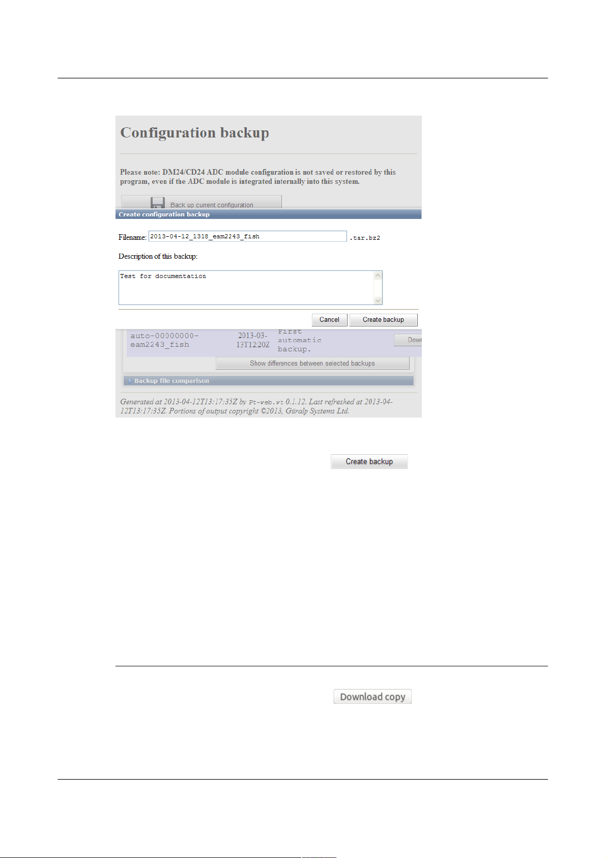
Acquisition Modules and Platinum Firmware Platinum Overview
Clicking the back-up button displays the following pop-up window:
A default file-name is suggested but this can be over-written if desired. You
can also enter a description of the back-up, which will be displayed in the list
of stored configurations. Click to save the current
configuration to the internal storage. The new stored configuration will
appear in the list of stored configurations.
To save a configuration backup from the command line, enter
config-backup --backup --comment 'user description' file
or, in abbreviated form
config-backup -b -C 'user description' file
replacing user description with your own description of the backup,
within single quotation marks ('). The configuration will be saved to the file
specified by file.
4.4.3 Downloading a saved configuration
Using the web interface, choose the required configuration from the list of
saved backups and click the associated button. The backup will
be downloaded using your browser's normal download mechanism.
Saved configurations can also be downloaded using file transfer tools like scp
and sftp. Manually saved configuration backups can be found in
MAN-EAM-0003 44 Issue E - February 2014
Page 45

Acquisition Modules and Platinum Firmware Platinum Overview
/var/lib/config-backup and automatically saved configuration backups
can be found in /var/lib/config-backup.auto.
4.4.4 Uploading a saved configuration
Backups that have been saved to a PC can be restored to any acquisition
module – not just the one from which it was originally downloaded. This
provides a useful mechanism for maintaining a centralised configuration
library.
To upload a previously stored configuration backup, click the
button. Your operating system's standard file selection dialogue will open.
Navigate to the required file and select it, then click the button.
The uploaded configuration will then appear in the list of saved backups and
can be restored, if required, as described in the following section.
Saved configurations can also be uploaded using file transfer tools like scp
and sftp. They should be copied to /var/lib/config-backup.
4.4.5 Restoring a configuration
The same screen in the web interface is also used for restoring a
configuration. Simply select the required saved configuration from the list of
saved backups and click on the button.
The following screen will be displayed:
The date and time at which the backup was saved is shown; in the example
above, this is the 12th of April, 2013 at 11:43. The file name and description
of the backup are also given.
The “Restore network settings” check-box allows you to choose whether or
not to restore the network configuration or not. You should select this if, for
MAN-EAM-0003 45 Issue E - February 2014
Page 46

Acquisition Modules and Platinum Firmware Platinum Overview
example, you are configuring a spare unit to replace an existing system that
has been damaged. You should leave it unselected if, for example, you are
cloning a configuration across an array of systems (where each would need
their own, unique, network settings).
If you are happy that you wish to proceed, click . The backup
will be restored and the system will then automatically reboot so that the
restored configuration can take effect.
To restore a configuration backup from the command line, enter
config-backup --restore path-to-file
or, in abbreviated form
config-backup -r path-to-file
replacing path-to-file with the full path (directories plus file-name) of the
previously saved configuration backup file.
If you wish to avoid overwriting the network settings, use
config-backup --restore --no-network path-to-file
or, in abbreviated form
config-backup -r -N path-to-file
The system will automatically reboot after restoring the configuration so that
the new settings can take effect. If you don't require the system to
automatically reboot, add --no-reboot or -R to the options, as in
config-backup --restore --no-reboot path-to-file
or, in abbreviated form
config-backup -r -R path-to-file
4.4.6 Comparing configurations
If more than one saved configuration backup is present on a system, any two
can be compared to show the differences. This is useful both to understand
what changes have been made to a system and also to compare two different
systems. To compare two systems, save a configuration backup on one,
download it to a PC, upload it to the second system (without restoring it) and
then use the comparison feature to reveal the differences between the two.
MAN-EAM-0003 46 Issue E - February 2014
Note: If you you are working on a remote system and have selected
“Restore network settings”, this action may sever your
communication link. Ensure that you understand the consequences
before proceeding.
Page 47

Acquisition Modules and Platinum Firmware Platinum Overview
Each stored configuration is displayed with two radio-buttons next to it, as
shown below:
To compare two saved configuration backups, select the left-hand-side
radio-button next to one of them and the right-hand-side radio-button next to
the other, and then click .
The differences are displayed in Linux diff format, with colour-coding used
to identify any lines that belong to one file but not the other. Detailed
explanation of the possible entries is beyond the scope of this document. A
simple introduction to the output from the diff command is available at
http://lowfatlinux.com/linux-compare-files-diff.html.
To compare two saved configuration backups from the command line, enter
the command
config-backup --diff path-to-file1 path-to-file2
or, in abbreviated form
config-backup -d path-to-file1 path-to-file2
MAN-EAM-0003 47 Issue E - February 2014
Page 48

Acquisition Modules and Platinum Firmware Platinum Overview
replacing path-to-file1 and path-to-file2 with the full paths
(directories plus file-name) of the previously saved configuration backup files
to be compared.
4.4.7 Deleting saved configurations
It is possible to delete configuration backups that have been manually saved
as well as those that have been uploaded. Automatic configuration backups
cannot be deleted: the system will retain the last fifty stored backups and
delete any older ones, using the directory cleaner (see section 14.5.1 on page
246).
To delete a stored configuration backup, simply click the
button next to the unwanted backup, as highlighted in the screen-shot below.
Stored configuration backups can be deleted from the command line by
simply deleting the relevant file in /var/lib/config-backup (for
user-generated backups) and /var/lib/config-backup.auto for
automatically saved configuration backups. For example, the command
rm /var/lib/config-backup/2013-04-12_1131_MyEAM.tar.bz2
MAN-EAM-0003 48 Issue E - February 2014
Page 49

Acquisition Modules and Platinum Firmware Platinum Overview
will delete a backup performed at 11:31 UTC on the 12th of April, 2013 on a
system called “MyEAM”.
It is possible to examine the comments embedded in a manually saved
configuration backup file using the command
config-backup --examine path-to-file
or, in abbreviated form,
config-backup -x path-to-file
Either of the commands will display the comments which were entered by the
user (in the “Description” field of the web interface or using --comment from
the command line) when the backup was created.
4.4.8 Transferring backups between systems
If the command-line program, config-backup, is invoked in save or restore
mode without a filename argument, standard input or standard output is
used, as appropriate. This allows the command to be used in pipe-lines, as in
the following examples.
A configuration file can be created on a Platinum system and immediately
copied to a linux PC (without being saved on the Platinum system) with a
single command:
ssh root@platinum config-backup --backup > local.backup
where platinum is the hostname of the CMG-EAM or other Platinum system.
Likewise, the configuration of a running system can be copied to another with
commands like:
(from a Linux PC):
ssh root@platinum1 config-backup --backup | \
ssh root@platinum2 config-backup --restore --no-network
(from the target system):
ssh root@source config-backup -b | config-backup -rN
where source is the hostname of the system to be cloned. The argument -N
prevents the network configuration on the target machine from being
over-written.
4.4.9 Technical details
Stored configuration backups are gzipped tar volumes containing all
configuration files from the host system. They are each around 33 kilobytes
in size.
MAN-EAM-0003 49 Issue E - February 2014
Page 50

Acquisition Modules and Platinum Firmware Platinum Overview
Automatically-saved configurations are stored in the directory
/var/lib/config-backup.auto and a system-supplied directory-cleaner
instance deletes all but the most recent fifty files. Manually saved
configuration backups are stored in /var/lib/config-backup.
The command-line interface, config-backup, displays full usage details if
invoked with --help:
Program usage:
config-backup --backup [options] [filename]
config-backup --restore [options] [filename]
config-backup --examine [options] [filename]
config-backup --diff filename1 filename2
Options:
-h, --help Display this screen.
-V, --version Display program version number.
-b, --backup Perform a configuration backup.
-r, --restore Restore configuration from a backup.
-x, --examine Examine a backup file (prints comment).
-d, --diff Compare differences between 2 backups.
-q, --quiet Inhibit progress messages.
-s, --syslog Log to syslog rather than screen.
Backup options:
-C, --comment <text> Comment for this backup.
Restore options:
-R, --no-reboot Do not reboot after a restore.
-N, --no-network Do not restore network settings
(hostname, IP addresses).
MAN-EAM-0003 50 Issue E - February 2014
Page 51

Acquisition Modules and Platinum Firmware Platinum Firmware Upgrades
5 Platinum Firmware Upgrades
Platinum firmware is regularly updated to provide extra features, improve
performance and, occasionally, to correct errors. The upgrade process is
normally fast, simple and can be carried out remotely using either the web or
command-line interface (but see the important notes, below).
The upgrade process makes use of the rsync protocol which uses an elegant
and efficient algorithm to, effectively, transfer only the differences between
revisions; even within individual files. This significantly reduces the time
required compared to traditional upgrade methods.
5.1 Important notes regarding build 10,000
5.1.1 Significant changes at build 10,000
All systems that run Platinum, excluding the CMG-NAM, are based around
ARM microprocessors. Platinum relies on the Linux operating system and a
number of utility programs which are made freely available by the ARM
development community. In 2010, this community agreed a new
specification for the way that programs interact with the operating system and
each other. This specification is know as the Application Binary Interface, or
ABI. The new ABI was called the “EABI” and the original one was
retrospectively renamed the “OABI”, for old ABI. The two paradigms cannot
coexist and all new community development will be carried out using the
newer EABI.
For this reason, starting with build 10,000, Platinum development also moved
to the EABI.
Using the EABI requires the use of a different compiler and, to simplify
development, a similar compiler change has been made for CMG-NAM and
CMG-NAM64 development.
The decision to use the EABI and the new compiler has one significant
consequence – an upgrade from a build before 10,000 to a current build is
vulnerable to interruptions in a way that no other upgrade is. This has
implications for systems installed in remote locations.
5.1.2 Systems installed in remote locations
Programs using the EABI cannot interoperate (on the same processor) with
programs using the OABI. There are also problems when mixing programs
MAN-EAM-0003 51 Issue E - February 2014
Note: This procedure does not upgrade the firmware of connected
or embedded digitisers, which should be upgraded using the web
interface or the dm24-upgrade command as documented in section
8.2.3 on page 115.
Page 52

Acquisition Modules and Platinum Firmware Platinum Firmware Upgrades
built using the two different compilers. For this reason, it is important that an
upgrade from build 3801 to build 10,000 or later is not interrupted.
The upgrade mechanism has, until now, been extremely tolerant of
interruptions and it has been normally sufficient to simply restart an
interrupted upgrade process. This will also be true for future upgrades, once
build 10,000 or higher has first been installed.
For upgrades from build 3801 to build 10,000 or later, however, it is highly
recommended that an upgrade to an acquisition module only be carried out in
a situation with a stable power supply, a reliable internet connection and
where you have physical access to the unit.
5.1.3 Procedures for upgrades spanning build 10,000
5.1.3.1 CMG-EAMs
An extra step must be taken when upgrading from build 3801 to the latest
build and special attention must be paid to the amount of free disk space
available. Please see this article on our web site for complete information and
detailed instructions:
www.guralp.com/articles/20110309-EAM-EABI-upgrade
5.1.3.2 CMG-NAMs and CMG-NAM64s
After upgrading from build 3801 to the latest build, you may see several
FATAL: kernel too old messages. In order to resolve this issue, please
log in to the command line as root and run the command:
/sbin/manual-post-upgrade
If, despite all precautions, the upgrade is interrupted at a crucial time, attempt
first to restart the upgrade. If this fails, please follow the recovery instructions
available from our web site at:
www.guralp.com/articles/20110318-NAM-recovery
5.1.3.3 CMG-DCMs
When upgrading a CMG-DCM, the upgrade process should be carried out
twice. The second run will resolve problems with broken symlinks. During
the first upgrade run, you may see several errors about “Directory not
empty” and references to broken files. These are normal and the second
upgrade invocation is designed to resolve these problems and leave the
system in a consistent state.
5.2 Determining the current firmware level
To determine the current firmware version from the web interface, select:
Summary → System status
MAN-EAM-0003 52 Issue E - February 2014
Page 53

Acquisition Modules and Platinum Firmware Platinum Firmware Upgrades
and click on the “Linux system” tab. The screen displays the current version
information:
In the example above, the version is 12642.
The same information can be obtained at the command line by using
gconfig and selecting “Version and serial number information”. If you just
want quick access to the software build number, this is contained in the file
/etc/build.version, which can be read with the command:
eam2243 ~ # cat /etc/build.version
# Overall build version
BUILD_LABEL="platinum-stable"
BUILD_VERSION="12642"
eam2243 ~ #
The version, in this case, can be seen to be 12642.
5.3 Upgrade Methods
This section describes three different methods of upgrading the firmware.
In order to be upgraded, the unit needs access to the latest version of the
firmware. If an internet connection is available, Güralp Systems Ltd's
software repository can be used. This method is described in section 5.3.1 on
page 54.
MAN-EAM-0003 53 Issue E - February 2014
Page 54

Acquisition Modules and Platinum Firmware Platinum Firmware Upgrades
If a number of units share a common network but that network is not
connected to the internet, you can make you own copy of the software
repository on a PC or laptop, which can be connected the network either
permanently or temporarily, and use that as the upgrade source. This method
is described in section 5.3.2 on page 55.
If one or more units are to be upgraded but Internet access is not available, the
new firmware can be copied to a USB storage device, such as a memory stick,
and the upgrade performed from that. This method is described in section
5.3.3 on page 59.
5.3.1 Upgrading via the internet
In order to upgrade over the Internet from Güralp Systems Ltd's software
repository, the unit must have its networking properly configured. In
particular, a DNS (Domain Name Service) server and a default gateway (or
default route) must both be configured. It is advisable to check these before
proceeding or in the event of problems preventing a successful upgrade.
To check for correct configuration of both of these items, issue the command:
ping -c3 rsync.guralp.com
This will send three “echo request” packets to the GSL upgrade server and
listen for responses. If both the DNS server and the correct gateway (default
router) are configured, the output will look like this:
eam2010 ~ # ping -c3 rsync.guralp.com
PING rsync.guralp.com (80.68.92.160): 56 data bytes
64 bytes from 80.68.92.160: seq=0 ttl=55 time=58.280 ms
64 bytes from 80.68.92.160: seq=1 ttl=55 time=66.845 ms
64 bytes from 80.68.92.160: seq=2 ttl=55 time=56.413 ms
--- rsync.guralp.com ping statistics --3 packets transmitted, 3 packets received, 0% packet loss
round-trip min/avg/max = 56.413/60.512/66.845 ms
eam2010 ~ #
If the DNS server is correctly configured but the gateway is not correctly
configured, the output will look like this:
eam2010 ~ # ping -c3 rsync.guralp.com
PING rsync.guralp.com (80.68.92.160): 56 data bytes
ping: sendto: Network is unreachable
eam2010 ~ #
If you are using DHCP, it is advisable to correct this problem by reconfiguring
the DHCP server to supply the correct route. If you are using static
addressing, enter the address of the Internet gateway router in the “Default
route (gateway)” field of the network interface configuration form. See section
7.1.2 on page 72 for more details.
MAN-EAM-0003 54 Issue E - February 2014
Page 55

Acquisition Modules and Platinum Firmware Platinum Firmware Upgrades
If the DNS server is not configured correctly (or at all), the output will look
like this:
eam2010 ~ # ping -c3 rsync.guralp.com
ping: bad address 'rsync.guralp.com'
eam2010 ~ #
If you are using DHCP, it is advisable to correct this problem by reconfiguring
the DHCP server to supply the correct name-server details. If you are using
static addressing, enter the address of a suitable DNS server in the
“Nameserver” field of the network interface configuration form (only available
in expert mode). See section 7.1.2 on page 72 for more details.
To check that your internet connection is correctly configured, enter the
command:
rsync rsync.guralp.com::
The output should look like this:
eam2010 ~ # rsync rsync.guralp.com::
platinum-crosslib Libraries required for cross-compiling
on the Platinum platform
platinum-stable Stable filesystems for the Platinum platform
platinum-builder Open source parts of Platinum firmware
build tree (large)
eam2010 ~ #
Any other output indicates a problem with your firewall – consult your
network administrator or see the trouble-shooting advice in section 16.4 on
page 270.
Once the network has been checked, you can proceed to upgrade the unit by
following the instructions in section 5.4 on page 61.
5.3.2 Upgrading from a local mirror
Setting up a mirror involves three steps:
1. Downloading the mirror content.
2. Setting up a local rsync server.
3. Configuring the client acquisition devices to use the new server.
MAN-EAM-0003 55 Issue E - February 2014
Note: If your internet connection is via a firewall, you must ensure
that port 873 (rsync) is open for TCP connections initiated by the
acquisition module. The following paragraphs explain how to
check this.
Note: Due to Windows file-system restrictions, it is only possible to
build a mirror server on a PC or laptop running Linux.
Page 56

Acquisition Modules and Platinum Firmware Platinum Firmware Upgrades
5.3.2.1 Downloading the mirror content
The mirror can occupy a significant amount of disk-space, depending on
which architectures you need to support. See the sections for each
architecture (below) for the current space requirements. You should pick a
file-system with ample space in which to store your own copy. In order to
simplify the download, we recommend that you start with an empty directory
each time. If you wish to make a fresh copy after a new firmware release, it is
much easier to create this in an empty directory than to "update" an existing
mirror. You can keep multiple, simultaneous versions of the firmware if you
wish and tell each acquisition device which version to use when upgrading.
The server on which you create the mirror should have access to the Internet
during the download step but does not need Internet access while it is acting
as an upgrade server. It does, of course, need to be accessible by your
networked acquisition devices. It is possible to create the mirror content on a
removable mass storage device attached to an Internet-connected computer
and then move the device to a different computer when performing the
upgrades. The removable mass storage device must use a Linux-compatible
file-system, such as ext3. FAT- and NTFS-formatted devices will not work
properly for this purpose.
Create the mirror directory and use the cd command to make it your current
directory. As root, enter one or more of the following command sequences to
download the mirror content. Each sequence downloads the files for a
particular architecture. If you know, for example, that you will never want to
upgrade a CMG-NAM64, you can omit the commands for this architecture.
CMG-DCMs
This architecture currently requires around 50MB of mass storage device
space for the mirror. The commands to download the content are:
GSLSRC=rsync.guralp.com/platinum-stable/CMG-DCM-mk2x
rsync -EgHloprtv --exclude resolv.conf rsync://$GSLSRC .
CMG-EAMs
There are currently two sets of firmware available for the CMG-EAM: a frozen
image of build 3801 (for users who do not yet wish to upgrade to post 10,000
builds) and the latest build.
If you do not wish to upgrade beyond build 3801 yet, the files for build 3801
require around 53MB of storage space for the mirror. Use the following
commands:
MAN-EAM-0003 56 Issue E - February 2014
Note: Be careful not to omit the final ‘.’ or the space before it in the
rsync commands below.
Page 57

Acquisition Modules and Platinum Firmware Platinum Firmware Upgrades
GSLSRC=rsync.guralp.com/platinum-stable/CMG-DCM-mk4
rsync -EgHloprtv --exclude resolv.conf rsync://$GSLSRC .
If the systems being upgraded are already at build 10,000 or later, you only
require the latest build, which occupies around 70MB of space. Use the
following commands:
GSLSRC=rsync.guralp.com/platinum-stable/CMG-DCM-mk4-eabi
rsync -EgHloprtv --exclude resolv.conf rsync://$GSLSRC .
If you are upgrading systems from earlier than build 3801 to the current build,
you will need both sets of firmware, requiring around 123MB of storage. Use
the following commands (note the additional punctuation):
GSLSRC='rsync.guralp.com/platinum-stable/CMG-DCM-mk4*'
rsync -EgHloprtv --exclude resolv.conf rsync://”$GSLSRC” .
CMG-NAMs
This architecture currently requires around 94MB of mass storage device
space for the mirror.
GSLSRC=rsync.guralp.com/platinum-stable/CMG-NAM
rsync -EgHloprtv --exclude resolv.conf rsync://$GSLSRC .
CMG-NAM64s
This architecture currently requires around 125MB of mass storage device
space for the mirror.
GSLSRC=rsync.guralp.com/platinum-stable/CMG-NAM64
rsync -EgHloprtv --exclude resolv.conf rsync://$GSLSRC .
5.3.2.2 Setting up a local rsync server
Your local rsync server is configured by creating the file /etc/rsyncd.conf.
If the serving host already runs an rsync server, you should modify this file
(by adding an extra module) in order to allow access from the acquisition
devices to the mirror directory: we assume that you have the knowledge to do
this without further assistance. This section covers setting up a new,
dedicated rsync server.
You will need to choose a TCP port number which will not conflict with
another service on your network. The port number should be greater than
1024 in order to avoid additional complexity. Consult your network
administrator for an available port or simply try 61616 and, if you get an error
saying that the port is in use when you attempt to start the server, choose a
different random number in the range 49152 - 65535. 61616 will be used in
the following example and should be replaced with the port number you have
chosen or been allocated. If there are firewalls between your server and the
acquisition devices, you will need to open channels through them for this
port.
MAN-EAM-0003 57 Issue E - February 2014
Page 58

Acquisition Modules and Platinum Firmware Platinum Firmware Upgrades
You will also need to choose a module name for the server. This can be any
descriptive string but, for simplicity, it is best to stick to numbers, lower-case
letters and hyphens (-). The name platinum-local-mirror has been used
in the following example and should be replaced with the module name you
have chosen.
Create the file /etc/rsyncd.conf with the following contents:
port = 61616
[platinum-local-mirror]
path = /path/to/your/local/mirror/directory
comment = GSL-EAM firmware
numeric ids = yes
log file = /path/to/writeable/log/file
timeout = 600
hosts allow = *
Consult the manual page for rsyncd.conf(5) for details of further options
that you can use in this file, including optional security improvements. This
is available on-line at http://man-wiki.net/index.php/5:rsyncd.conf.
Once the /etc/rsyncd.conf file is ready, you can start the rsync server
with the command
sudo rsync --daemon
If you want to run the rsync server permanently, it is possible to start it via
inetd, xinetd or an rc script. Consult the manual page for rsyncd.conf(5)
for further details.
5.3.2.3 Configuring the upgrade system to use the new server
The standard upgrade source must be over-ridden: on each system to be
upgraded. Create the file /etc/conf.d/upgrade.local with the following
contents:
RSYNC_HOST="address.of.my.server”
RSYNC_PORT="61616"
RSYNC_MODULE="platinum-local-mirror"
replacing:
• address.of.my.server with the DNS name or IP address of the
mirror server;
• 61616 with the port number you chose earlier; and
• platinum-local-mirror with the module name you chose earlier;
Note the quotation marks around the variables.
The acquisition devices can now be updated from the mirror by following the
instructions in section 5.4 on page 61. Note that the configuration files
MAN-EAM-0003 58 Issue E - February 2014
Page 59

Acquisition Modules and Platinum Firmware Platinum Firmware Upgrades
/etc/conf.d/upgrade.local on each acquisition devices will not be
disturbed by the upgrade process and, so, only need to be created once.
5.3.3 Upgrading from a USB storage device
For situations where it is either
impossible or undesirable to
upgrade over a network, Güralp
Systems Ltd can supply the latest
Platinum firmware on a USB
memory stick, along with an
appropriate adaptor cable, part
number CAS-DCM-0038.
The adapter cable is required
when upgrading the firmware of
most acquisition module units but
not when upgrading a CMG-NAM.
You will need both physical access and command-line access to the device
being upgraded. Command-line access may be via ssh or a serial connection.
To upgrade the firmware from a USB storage device:
1. Power up the USB ports (CMG-EAM only). The hardware for other
acquisition modules do not have control over the 5V USB supply and power is
always provided to the USB ports.
Depending on the revision of CMG-EAM firmware installed before the upgrade,
there are three possible commands for powering up the USB ports. Ignoring any
error messages, enter these commands at the terminal:
echo 1 > /sys/class/gpio/USBpowerB/level
ioline -L USBA_power -o 1
ioline -L USBB_power -o 1
2. Connect the firmware pod.
If you are upgrading a CMG-EAM, CMG-DAS or CMG-DCM, the supplied cable
(CAS-DCM-0038) should be attached to the 6-pin bayonet USB connector of the
module. The firmware pod is then connected to the end of this cable.
A CMG-NAM unit has standard USB sockets and these can be used to directly
connect the firmware pod. You may use the USB socket on the front (or any on the
rear) of the module.
MAN-EAM-0003 59 Issue E - February 2014
Note: Using the wrong command is completely harmless and
merely results in an error message, so it is easiest - and
perfectly safe - to simply enter all three commands at the
terminal.
Page 60

Acquisition Modules and Platinum Firmware Platinum Firmware Upgrades
3. Wait for the device to be scanned and registered by the operating system. You
can confirm this by looking for USB mass storage registration entries in the system
log file, /var/log/messages.
4. Mount the file system by entering the following command:
mount -t ext2 -o ro /dev/disk/by-label/Pt-firmware /mnt
5. Run the upgrade script.
This is not the same script that is used for network upgrades but it takes the same
optional arguments. These arguments are documented in section 5.4 on page 61,
which should be read before proceeding.
Once you have decided which argument, if any, you wish to use, run the script
with the command:
/mnt/upgrade optional_argument
6. Ensure there are no error messages and then reboot the device. Once the unit
has rebooted, the upgrade process is complete.
5.3.4 U3 USB mounting problems
U3 was a method of launching Windows applications from special USB flash
drives. A U3 flash drive presents itself to the host system as a USB hub with a
CD drive and standard USB mass storage device attached.
Reformatting the drive will remove some of the software (the hidden
"SYSTEM" folder), but not all of it. The virtual CD-ROM drive cannot be
removed by reformatting because it is presented to the host system as a
physical device attached to a USB hub.
U3 Tool is an open-source management tool (for Windows and Linux) that
allows the locked U3 partition to be removed.
The U3 tool is available from http://resourcelessness/projects/u3-tool/files/.
MAN-EAM-0003 60 Issue E - February 2014
Note: Some early Platinum releases only had ext3 file-system
support. If this is the case, the above command will result in
an "Invalid argument" error message. If this occurs, simply
change ext2 in the above command to ext3.
Note: Certain upgrades (depending on the initial version number)
make it difficult or impossible to reboot the system via the web
interface. In these cases, the system can be rebooted from the
command line (with the reboot command) or by power-cycling.
Page 61

Acquisition Modules and Platinum Firmware Platinum Firmware Upgrades
5.3.4.1 MS Windows
Open a command prompt and change the directory to that where the U3 tool
was installed. To see all options, enter the command:
u3-toolmaker
To repartition the device, enter the command:
u3-toolmaker -p 0 E
replacing E with the device's drive letter
5.3.4.2 Linux 2.6.20+
To see all options, enter the command:
u3-tool
To repartition the device enter the command:
./u3_tool -U /dev/sg3
Replace /dev/sg3 with the SCSI generic device associated with your device.
The correct device can be deduced from the output from the command
dmesg.
5.3.4.3 Linux 2.4
To unlock the “secured data partition” using Linux's USB subsystem:
# modprobe -r usb-storage
# ./u3_tool -u scan
# modprobe usb-storage
After unlocking, the device can be used normally.
5.4 Upgrade Types
There are three different types of upgrade, each of which is described below.
When upgrading via the web interface, the desired type is selected by pressing
the appropriate button. When upgrading directly from the command line or
from a USB storage device, the required type is selected by the use or
omission of command-line arguments.
5.4.1 Standard upgrade
The standard upgrade brings the firmware to the latest revision while
respecting and preserving all configuration settings.
MAN-EAM-0003 61 Issue E - February 2014
Page 62
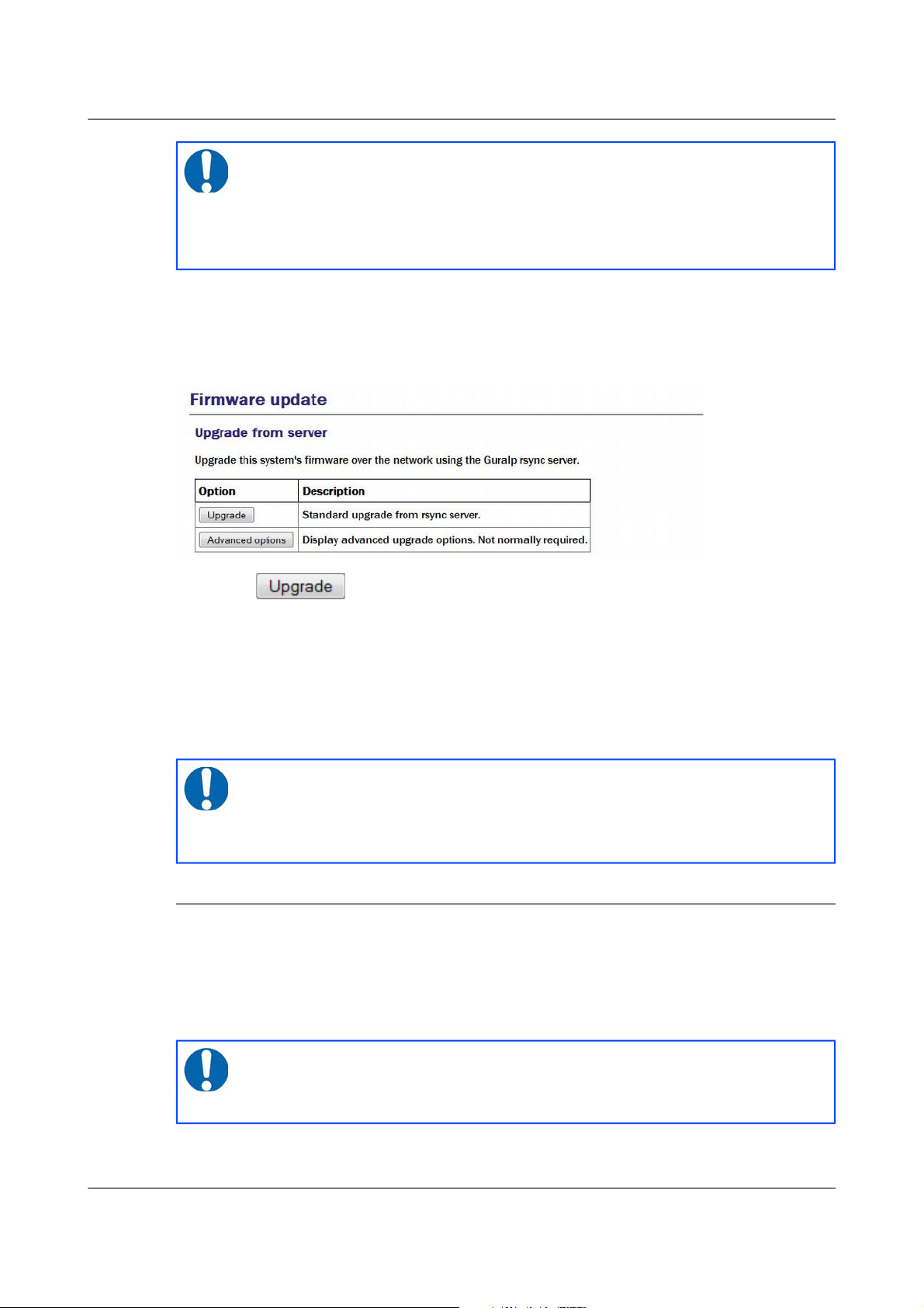
Acquisition Modules and Platinum Firmware Platinum Firmware Upgrades
To perform a standard upgrade from the web interface, select:
Tools → Firmware
The following screen will be displayed:
Press the button and watch the screen for any error messages.
To perform the same upgrade from the command line, simply enter the
command:
eam999 ~ # upgrade
with no arguments. Watch the screen for any error messages and then reboot
to complete the process.
5.4.2 Upgrade and restore defaults
The standard upgrade respects and preserves user configuration settings. In
some circumstances it may be necessary to overwrite these settings and return
all configuration settings to their factory defaults. The unit is not completely
restored to factory condition: this allows for the possibility of implementing
customisations and user-developed scripts which persist across upgrades.
MAN-EAM-0003 62 Issue E - February 2014
Note: All files on any connected hard drive or USB drive are left
untouched, as are any files in the directories /home, /root, /var
and /usr/local. In addition, any file with an extension of
.local will be preserved: this is the mechanism by which most
configuration settings are safeguarded.
Note: Certain upgrades (depending on the initial version number)
make it difficult or impossible to reboot the system via the web
interface. In these cases, the system can be rebooted from the
command line (with the reboot command) or by power-cycling.
Note: All files on any connected hard drive or USB drive are left
untouched, as are any files in the directories /home, /root, /var
and /usr/local. Files with the extension .local are deleted.
Page 63

Acquisition Modules and Platinum Firmware Platinum Firmware Upgrades
To restore defaults while upgrading from the web interface, select:
Tools → Firmware
and then click
The following screen will be displayed:
The first button, , does exactly the same as the similar button on
the previous screen. The button performs the action
described in this section.
To perform this action from the command line, invoke the upgrade script with
the argument --restore-defaults:
eam999 ~ # upgrade --restore-defaults
Watch the screen for any error messages and then reboot the unit to complete
the process.
5.4.3 Upgrade and force factory defaults
The third upgrade option effectively wipes everything (other than files on any
connected hard drive or USB drive) while installing the new firmware
revision, leaving the unit as it would be delivered. Avoid using this option if
you have made any customisations to your unit or installed any scripts. If in
doubt, please consult Güralp Systems Ltd technical support for advice before
proceeding. Conversely, if you have made changes which you believe have
adversely affected the unit but are having trouble undoing them, this option
lets you start with a clean slate.
MAN-EAM-0003 63 Issue E - February 2014
Note: Certain upgrades (depending on the initial version number)
make it difficult or impossible to reboot the system via the web
interface. In these cases, the system can be rebooted from the
command line (with the reboot command) or by power-cycling.
Page 64

Acquisition Modules and Platinum Firmware Platinum Firmware Upgrades
To invoke this option from the web interface, select “Firmware” from the
“Tools” menu and then click the button. From the resulting
screen, press the button. Watch the screen for
any error messages and then reboot the unit to complete the process.
To perform this action from the command line, invoke the upgrade script with
the argument --force-factory-settings:
eam999 ~ # upgrade --force-factory-settings
Watch the screen for any error messages and then reboot the unit to complete
the process.
5.5 Upgrade logs
The upgrade process stores all progress and error messages in the file
/var/log/upgrade.log. If you suspect that there has been a problem with
an upgrade or you wish to have full details of what has changed, you can
inspect this file by issuing the command
eam999 ~ # less /var/log/upgrade.log
You can scroll forward through the file simply by pressing the
key. For more control, you can move forward and
backwards, line by line, with the and keys or, page by page, with the
and keys.
The key should be used to return to the command line.
If you wish to obtain a copy of this log file, it can be copied from the system to
an external computer either via the serial port (see section 11.3.1.4 on page
157) or over the network (see section 11.3.1.2 on page 152).
MAN-EAM-0003 64 Issue E - February 2014
Note: Certain upgrades (depending on the initial version number)
make it difficult or impossible to reboot the system via the web
interface. In these cases, the system can be rebooted from the
command line (with the reboot command) or by power-cycling.
Page 65

Acquisition Modules and Platinum Firmware Data Handling
6 Data Handling
6.1 Introduction
The data handling system of the acquisition module is very flexible, due to its
modular software architecture. In the simplest configuration, all data flowing
through the acquisition module is routed through a single multiplexor module
called gdi-base. This communicates directly with all input modules, which
handle the various incoming data streams, and all output modules, which
convert the data into the required formats. All incoming data are stored and
accessed internally in an intermediate format, regardless of the format in
which it was originally received.
The diagram below shows the basic internal organisation of an acquisition
system, ignoring the CD1.1 subsystem:
The multiplexor makes incoming data available to the output modules. These
come in two flavours: simple modules (such as those for WIN, GSMS and
QSCD) simply convert the data streams and output them in the required
format; other modules maintain a ring-buffer which is used to, for example,
satisfy BRP back-fill requests. The ring-buffers use the NAND flash memory.
These output modules also send data to gdi-record, which handles all mass
storage device writing requests, regardless of format.
MAN-EAM-0003 65 Issue E - February 2014
Note: The sole exception to this is incoming CD1.1 data which, for
reasons related to frame signing (an authentication technology), do
not pass through gdi-base. CD1.1 data-handling and the
associated system configuration are covered in a separate manual,
MAN-EAM-1100, which is available for download from
www.guralp.com.
Page 66

Acquisition Modules and Platinum Firmware Data Handling
The gdi-base and gdi-record programs are designed to be stateless, so
that the data on the mass storage device are always consistent. This means
the system is tolerant of power interruptions and of the mass storage device
being removed without notice.
Any number of input modules can be configured to acquire data in any
supported format from any source, simultaneously. These modules convert
their data and pass it to the multiplexor. Data can be acquired in any of the
following formats, from multiple sources:
• BRP via serial lines
• Scream, via Ethernet or ppp
• GDI-link, via Ethernet or ppp
• CD1.1
The architecture has been designed to support the addition of extra formats
simply by adding input modules. Please contact Güralp Systems if you have
requirements which are currently unsupported.
Any number of output modules can be configured to send data in any
supported format to any destination. The following data formats are
supported:
• GCF output via serial port or TCP stream
• GCF output via Scream (TCP or UDP)
• SEEDlink
• CD1.1;
• GDI (Güralp Data Interconnect)
• GDI-link
• WIN format output
• QSCD - Quick Seismic Characteristic Data (designed by KIGAM) output
• GSMS (Güralp Seismic Monitoring System) output
In the default, factory configuration, the acquisition module is configured to
receive serial GCF input on all of its serial ports except Data Out. There is a
single chain of data through the multiplexor to a Scream server. Data are also
recorded to the configured mass storage device in GCF format. This is shown
in the following diagram:
MAN-EAM-0003 66 Issue E - February 2014
Page 67

Acquisition Modules and Platinum Firmware Data Handling
The gdi2gcf module, know as the GCF compressor, is responsible for
re-blocking GDI samples into GCF blocks. It provides data to all GCF output
modules as well as to the gdi-record module, which writes GCF files to the
mass storage device. It has a number of configuration options, which are
described in section 11.2 on page 138.
A similar arrangement applies to miniSEED data: the gdi2miniseed module
provides data to the SEEDlink server and to gdi-record.
6.2 Configuring gdi-base
The gdi-base module requires no configuration in most applications. For
very complex situations, however, it may be necessary to create additional
MAN-EAM-0003 67 Issue E - February 2014
Page 68

Acquisition Modules and Platinum Firmware Data Handling
instances. The information in this section is provided the interests of
completeness.
To configure a gdi-base instance on the acquisition module from the web
interface, select:
Configuration → Service → Expert → Advanced
or
Configuration → All options → System services → Expert → Advanced
To configure an instance from the command line, start gconfig and select
“System services” from the top level menu.
Now select “gdi-base -- Data transport and channel manager”.
The screen shows a list of all gdi-base instances that have been configured.
Select the appropriate link to edit an existing instance or to create a new one.
6.2.1 Configurable parameters
The configurable parameters for gdi-base are contained in a single form:
User description: Sets the name of the instance; this should be set to a
meaningful name for the function it will be performing.
Socket: Allows specification of the inter-process communication socket used
by this instance. This should not normally be changed.
Log file: It may sometimes be desirable, for debugging purposes, to separate
log messages for this transmitter from the standard system log. The text field
MAN-EAM-0003 68 Issue E - February 2014
Page 69

Acquisition Modules and Platinum Firmware Data Handling
can be populated with a path name which will then be used for dedicated
logging. If left blank, logging occurs (via the standard Linux syslog facility) to
/var/log/messages.
Log level: The drop-down menu controls the level of detail present in log
messages, whether to syslog or to a dedicated log file. Not all of the standard
syslog logging levels are available. The menu offers a choice (in order of
decreasing detail) of:
• Debugging information
• Informational messages
• Important notices
• Warnings
Metadata directory: Allows specification of the directory where this instance
stores intermediate information. This should not normally be changed
6.3 Using compressors
The two compressors mentioned at the beginning of section 6 on page 65
convert from GDI to GCF and from GDI to miniSEED format. They provide
channel filtering, channel name mapping and data buffering for the
gdi-record module, which writes GCF and miniSEED files to the mass
storage device.
One instance each of gdi2gcf and gdi2miniseed are present in the default
configuration. Additional instances may be created as required. This will be
necessary if you have different channel filtering requirements for, say,
recording and transmitting or if you need different transmitters to send
different sets of channels to different destinations. The configuration page for
every transmitter has, in the “Expert mode” options, a drop-down menu
which allows the operator to select which compressor instance to use for its
input. The gdi-record configuration page has a similar facility.
Instances of either compressor are “dependant services”, meaning that they do
not need to be (and should not be) configured to start automatically when the
system boots. They will be started whenever a client service, such as a
connected transmitter (or gdi-record), starts.
Configuration of the GCF compressor, gdi2gcf, is described in section 12.1.1
on page 162.
Configuration of the miniSEED compressor, gdi2miniseed, is described in
section 12.2.1 on page 180.
MAN-EAM-0003 69 Issue E - February 2014
Page 70

Acquisition Modules and Platinum Firmware Networking Configuration
7 Networking Configuration
Platinum firmware includes comprehensive support for Ethernet networking.
Features include VLAN (virtual network) support, a PPP implementation (IP
over serial lines), an iptables firewall and IPV6 support.
Minimal network configuration is described in section 3.2 on page 20. Those
steps will allow you to communicate with your device over a network. The
configuration changes made in that way will not, however, survive a reboot.
To make the configuration permanent, follow the procedures in this section.
7.1 Configuring physical network interfaces
Most acquisition modules have a single physical network interface.
CMG-NAMs are typically equipped with multiple physical network interfaces.
Platinum firmware follows the standard Linux convention of naming the first
physical network interface present on a system eth0 and subsequent
interfaces eth1, eth2, etc.
To configure a physical network interface from the web interface, select:
Configuration → Networking → Interfaces
or
Configuration → All options → Networking
The following screen will be displayed:
To configure a physical network interface from the command line, start
gconfig and select “Networking” from the top level menu.
The first link on the screen takes you to the configuration page for the first
physical network interface. If your hardware has multiple physical interfaces,
you may need to create configurations for them using the “Create a new
interface” button. Once created, the can be configured in an identical manner
to eth0, as described below.
MAN-EAM-0003 70 Issue E - February 2014
Page 71

Acquisition Modules and Platinum Firmware Networking Configuration
7.1.1 Configurable parameters in simple mode
The configurable parameters for physical network interface have two tabs in
simple mode: Interface and Static IP.
7.1.1.1 Interface
Device: Not editable. It displays the name of the network interface being
configured.
MAC address: Not editable. It shows the Media Access Control address of the
adapter's hardware. It is often useful to know this when configuring DHCP
servers: by binding an IP address to a particular MAC address, the DHCP
administrator can ensure that the device retains the same IP address across
reboots.
Description: Allows the operator to modify the description of this interface in
configuration dialogues and error messages. This is of limited value when
there is only a single interface but, for example, when a CMG-NAM has
multiple interfaces, it may be useful to rename them in order to reflect their
logical function rather than their physical position.
Enable interface: Enables the interface when checked. No other configuration
settings are changed when the interface is disabled, allowing use of the
interface to be suspended without deleting the configuration.
Startup enable: Controls whether the interface is enabled automatically when
the unit boots.
Enact on submit: Controls whether changes made using the rest of this form
take effect immediately or are only written to the configuration files. When
MAN-EAM-0003 71 Issue E - February 2014
Page 72

Acquisition Modules and Platinum Firmware Networking Configuration
this box is cleared, changes will only take effect the next time the unit is
booted or the interface is reconfigured with this box ticked.
Configuration method: The drop-down menu offers the following choices:
• Static: The interface will take its address and routing parameters from
values entered by the operator.
• DHCP (Dynamic Host Configuration Protocol): The interface will
attempt to obtain its address and routing parameters from a DHCP server.
• Unconfigured but powered up (possible VLAN trunk): The interface
will not be used directly but is available for carrying virtual network
(VLAN) traffic.
• Powered off: The interface will not be used and the interface chip is
disabled, reducing the total power consumption by around 200mW.
7.1.1.2 Static IP
IP address: Only used if the Configuration method drop-down menu is set to
“Static”. The address should be entered in CIDR format, where the address is
followed by a slash and then the number of bits defining the netmask, e.g.
192.168.0.1/24 for IPV4 or 2001:db8:/32 for IPV6.
For more information about CIDR, please refer to:
http://en.wikipedia.org/wiki/Classless_Inter-Domain_Routing.
Default route (gateway): Should be populated with the IP address of the
default router. If more complicated routing configurations are required, these
can be entered in expert mode.
7.1.2 Configurable parameters in expert mode
When in expert mode new fields are available on the “Interface” and “Static
IP” tabs and there are three new tabs: DCHP options, IP aliasing and Routes.
7.1.2.1 Interface (Expert)
Media type/speed: This drop-down menu offers the following options for
controlling the communication speed and duplex mode of the network link:
MAN-EAM-0003 72 Issue E - February 2014
Page 73

Acquisition Modules and Platinum Firmware Networking Configuration
• Automatically detected and set
• Restrict speed to 10Mbps. Recommended to save power
• Fixed 100baseTx, full duplex
• Fixed 100baseTx, half duplex
• Fixed 10baseTx, full duplex
• Fixed 10baseTx, half duplex
MTU: Allows the Maximum Transfer Unit to be set for the network link.
This parameter controls the maximum packet size used for outgoing network
packets. If any segment of a link between two systems has a restriction on
packet size, larger packets flowing across the link must be fragmented broken into smaller parts - and then re-assembled on arrival. This is
inefficient and can badly affect the throughput of a link. In such situations, it
makes sense to restrict the maximum packet size at the sender (to match the
limitation) so that all packets can pass unimpeded.
There is no method to empirically determine the optimum MTU for a given
link from the acquisition module itself but, if the link is to a PC (or, in the
case of, say, a link between two acquisition modules, one end can temporarily
be replaced by a PC) the PC can be used to investigate the link properties and
the correct value can be obtained.
For more information, please see http://www.dslreports.com/faq/695. Note
that, if testing from a PC running Windows, the MTU of the Windows PC
should be set to 1500 before starting the test.
7.1.2.2 DCHP options
Extra dhcpcd arguments: Used to change the operation of the DHCP client.
Please see http://man-wiki.net/index.php/8:dhcpcd for information about what
options can be added here.
7.1.2.3 Static IP (Expert)
Extra ip addr arguments: Used to tune the operation of the network interface.
A non-standard broadcast address can be specified by entering broadcast
broadcast_address. For other settings that can be used here, please see
http://linux.die.net/man/8/ip.
MAN-EAM-0003 73 Issue E - February 2014
Page 74
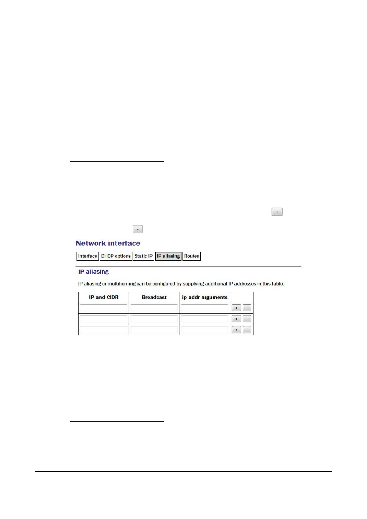
Acquisition Modules and Platinum Firmware Networking Configuration
Nameserver: Used to specify the IP address of the DNS server for your
network. This field must be set correctly before internet firmware upgrades
can be used. A secondary DNS server's address can be added in the Backup
nameserver field.
Default route (gateway): Populate with the IP address of the gateway router,
for access to other networks or to the Internet. This field must be set correctly
before internet firmware upgrades can be used.
IP route arguments: Used to modify the invocation of the ip route add
command in order to, e.g., set the route metric. The options that can be set
here are mostly highly technical and should rarely be required. Please see
http://linux.die.net/man/8/ip for more information.
7.1.2.4 IP aliasing
IP aliasing is used to add extra addresses to this interface, a technique known
as multi-homing. By default, the table displays three blank rows but, should
you need more, complete the first three and submit the form: it will be
re-drawn with extra blank rows. Alternatively, clicking the button on any
row will open a new row. In the same way, rows can be deleted by clicking
the corresponding button.
IP and CIDR: The address should be entered in CIDR format, where the
address is followed by a slash and then the number of bits defining the
netmask, e.g. 192.168.0.1/24 for IPV4 or 2001:db8:/32 for IPV6.
Broadcast: Enter the broadcast address to be associated with this address on
the interface.
IP addr arguments: This field can be used to tune the operation of the
network interface. For settings that can be used here, please see
http://linux.die.net/man/8/ip.
7.1.2.5 Routes
Routes are used to add extra network and host routes to allow access to
networks other than those connected via the default router specified earlier,
MAN-EAM-0003 74 Issue E - February 2014
Page 75
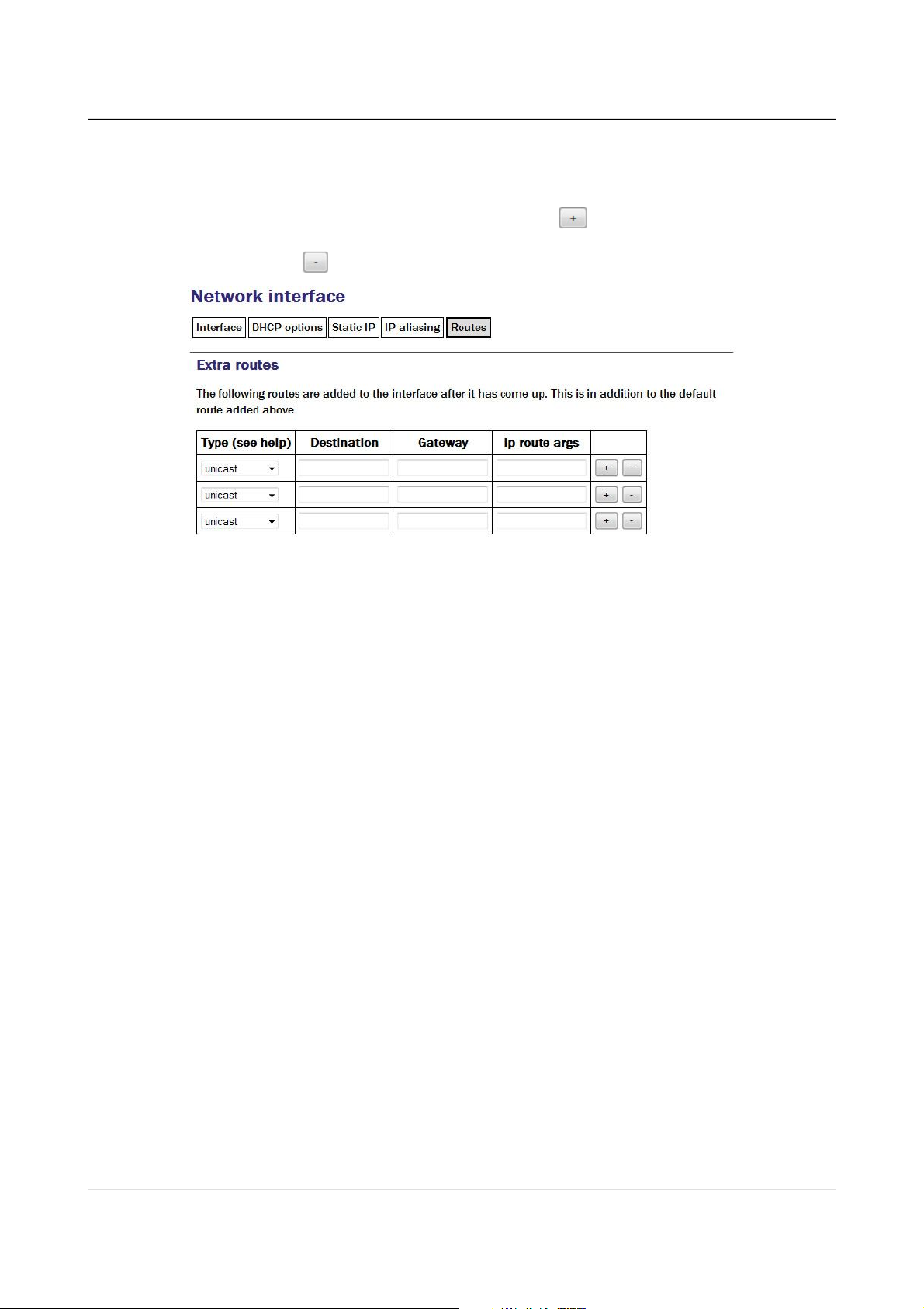
Acquisition Modules and Platinum Firmware Networking Configuration
or to force packets to traverse a particular route despite the default router
setting. By default, the table displays three blank rows but, should you need
more, complete the first three and submit the form: it will be redrawn with
extra blank rows. Alternatively, clicking the button on any row will open
a new row. In the same way, rows can be deleted by clicking the
corresponding button.
Type: This drop-down menu offers the following choices:
• unicast - This is the normal setting for a host or network route. The
route entry describes real paths to the destinations specified in the
Destination column.
• unreachable - these destinations are unreachable. Packets are discarded
and the ICMP message host unreachable is generated. An
EHOSTUNREACH error may appear in /var/log/messages.
• blackhole - these destinations are unreachable. Packets are discarded
silently. An EINVAL error may appear in /var/log/messages.
• prohibit - these destinations are unreachable. Packets are discarded and
the ICMP message communication administratively prohibited is
generated. An EACCES error may appear in /var/log/messages.
• local - the destinations are assigned to this host. The packets are looped
back and delivered locally.
• broadcast - the destinations are broadcast addresses. The packets are
sent as link broadcasts.
Destination: The host or network to which this route offers access should be
entered here in CIDR format, where the address is followed by a slash and
then the number of bits defining the netmask, e.g. 192.168.0.1/24 for IPV4
or 2001:db8:/32 for IPV6.
Gateway: The IP address of the host which serves as the gateway to the
specified destination.
MAN-EAM-0003 75 Issue E - February 2014
Page 76

Acquisition Modules and Platinum Firmware Networking Configuration
IP route args: Used to modify the invocation of the associated ip route
add command in order to, e.g., set the route metric. The options that can be
set here are mostly highly technical and should rarely be required. Please see
http://linux.die.net/man/8/ip for more information.
7.2 Wireless Networking
CMG-EAM and CMG-DAS units equipped with wireless networking hardware
can function as clients for Wireless Access Points or participate in ad-hoc
wireless networks.
To configure a wireless network interface from the web interface, select:
Configuration → Networking → Interfaces
or
Configuration → All options → Networking
The following screen will be displayed:
Now select 'wlan0 – Wireless interface wlan0':
You can change the description of the wireless network if you wish.
To configure a wireless network interface from the command line, start
gconfig and select “Networking” from the top level menu:
Existing defined networks can be reconfigured by clicking on the link and
new networks can be defined by clicking on the “Create new network” link.
MAN-EAM-0003 76 Issue E - February 2014
Page 77

Acquisition Modules and Platinum Firmware Networking Configuration
7.2.1 Configurable parameters in simple mode
The configurable parameters for wireless networking have three tabs in
simple mode: Network, Access Point and IP Address.
7.2.1.1 Network
Network description: Enter a descriptive name of the network.
7.2.1.2 Access Point
MAN-EAM-0003 77 Issue E - February 2014
Page 78

Acquisition Modules and Platinum Firmware Networking Configuration
SSID: Specifies the Service Set Identifier (network name) for the desired
wireless network.
Priority: Used to decide which network is chosen for connection when
several configured networks are detected: connections to networks with
higher priority numbers are attempted first.
Key management: Drop-down menu used to select which authentication
strategy is used for this network. If WPA-PSK (WiFi Protected Access,
pre-shared keys) is chosen, the following fields allow the operator to specify
one or more access keys (passphrases).
7.2.1.3 IP address
The IP address screen allows the selection of DHCP (Dynamic Host
Configuration Protocol) or static addressing. If DHCP is chosen, a DHCP
server will provide the unit with an IP address as well as the IP address of a
default router (gateway) and, optionally, other parameters such as the address
of a DNS server (name-server).
If static addressing is selected, the desired IP address and default router must
be specified in the following two fields.
7.2.2 Configurable parameters in expert mode
When in expert mode new fields are available on the network and IP address
forms and there are two new tabs: IP aliasing and Routes.
MAN-EAM-0003 78 Issue E - February 2014
Page 79

Acquisition Modules and Platinum Firmware Networking Configuration
7.2.2.1 Network
MTU: This field allows you to define a Maximum Transmission Unit (the size
of the largest packet that a network protocol can transmit) for the associated
network. A value which is too small will cause inefficient packetisation
whereas one which is too large will cause packet fragmentation and possible
disruption to communication. See the discussion in section 7.1.2 on page 72
for more information.
7.2.2.2 IP Address
Extra dhcpcd options: Used to change the operation of the DHCP client.
Please see http://man-wiki.net/index.php/8:dhcpcd for information about what
options can be added here.
MAN-EAM-0003 79 Issue E - February 2014
Page 80
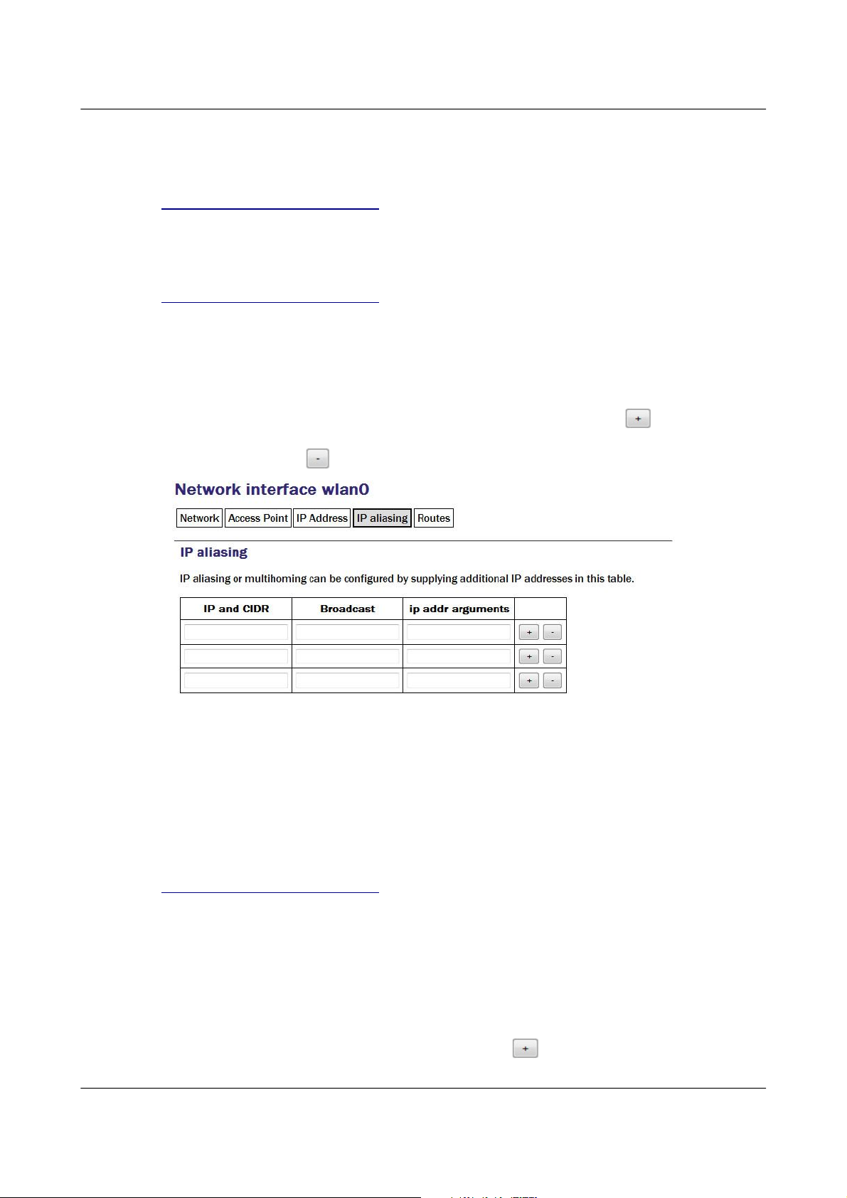
Acquisition Modules and Platinum Firmware Networking Configuration
Extra IP addr arguments: Used to tune the operation of the network interface.
A non-standard broadcast address can be specified by entering broadcast
broadcast_address. For other settings that can be used here, please see
http://linux.die.net/man/8/ip.
IP route arguments: Used to modify the invocation of the ip route add
command in order to, e.g., set the route metric. The options that can be set
here are mostly highly technical and should rarely be required. Please see
http://linux.die.net/man/8/ip for more information.
7.2.2.3 IP aliasing
The IP aliasing table is used to add extra addresses to this interface, a practice
known as multi-homing. By default, the table displays three blank rows but,
should you need more, complete the first three and submit the form: it will be
redrawn with extra blank rows. Alternatively, clicking the button on any
row will open a new row. In the same way, rows can be deleted by clicking
the corresponding button.
IP and CIDR: The address should be entered in CIDR format, where the
address is followed by a slash and then the number of bits defining the
netmask, e.g. 192.168.0.1/24 for IPV4 or 2001:db8:/32 for IPV6.
Broadcast: Enter the broadcast address to be associated with this address on
the interface.
IP addr arguments: This field can be used to tune the operation of the
network interface. For settings that can be used here, please see
http://linux.die.net/man/8/ip.
7.2.2.4 Extra routes
Routes are used to add extra network and host routes to allow access to
networks other than those connected via the default router specified earlier,
or to force packets to traverse a particular route despite the default router
setting. By default, the table displays three blank rows but, should you need
more, complete the first three and submit the form: it will be redrawn with
extra blank rows. Alternatively, clicking the button on any row will open
MAN-EAM-0003 80 Issue E - February 2014
Page 81

Acquisition Modules and Platinum Firmware Networking Configuration
a new row. In the same way, rows can be deleted by clicking the
corresponding button.
Type: The drop-down menu offers the following choices:
• unicast: Normal setting for a host or network route. The route entry
describes real paths to the destinations specified in the Destination
column.
• Unreachable: Destinations are unreachable. Packets are discarded and
the ICMP message host unreachable is generated. An EHOSTUNREACH
error may appear in /var/log/messages.
• Blackhole: Destinations are unreachable. Packets are discarded silently.
An EINVAL error may appear in /var/log/messages.
• Prohibit: Destinations are unreachable. Packets are discarded and the
ICMP message communication administratively prohibited is generated.
An EACCES error may appear in /var/log/messages.
• Local: Destinations are assigned to this host. The packets are looped
back and delivered locally.
• Broadcast: The broadcast addresses. The packets are sent as link
broadcasts.
Destination: The host or network to which this route offers access should be
entered here in CIDR format, where the address is followed by a slash and
then the number of bits defining the netmask, e.g. 192.168.0.1/24 for IPV4
or 2001:db8:/32 for IPV6.
Gateway: Enter the IP address of the host which serves as the gateway to the
specified destination.
ip route args: This field field can be used to modify the invocation of the
associated ip route add command in order to, e.g., set the route metric.
The options that can be set here are mostly highly technical and should rarely
be required. Please see http://linux.die.net/man/8/ip for more information.
MAN-EAM-0003 81 Issue E - February 2014
Page 82

Acquisition Modules and Platinum Firmware Networking Configuration
7.3 Virtual network (VLAN) interfaces
Platinum firmware supports the use of Virtual Local Area Networks (VLANs)
to partition network traffic on the same physical subnet. Virtual interfaces
can be created and assigned to a particular VLAN tag (ID) and a particular
physical interface. A full discussion of VLANs is beyond the scope of this
document.
To configure a virtual network interface from the web interface, select:
Configuration → Networking → Interfaces
or
Configuration → All options → Networking
The following screen is displayed:
To configure a VLAN interface from the command line, start gconfig and
select “Networking” from the top level menu.
Now select 'Create a new VLAN interface'
7.3.1 Configurable parameters in simple mode
The configurable parameters for virtual network interfaces have two tabbed
pages in simple mode: Interface and Static IP.
MAN-EAM-0003 82 Issue E - February 2014
Page 83
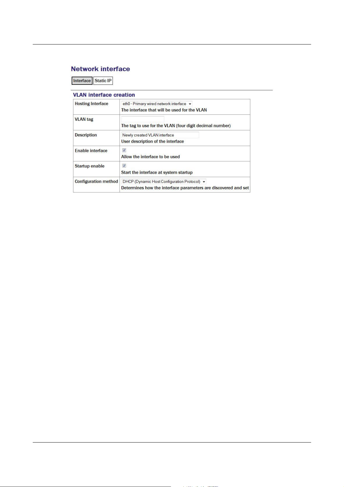
Acquisition Modules and Platinum Firmware Networking Configuration
7.3.1.1 VLAN Interface
Hosting Interface drop-down menu is populated with a list of the physical
interfaces present on the system. Select the physical interface over which you
wish this virtual interface's traffic to flow.
VLAN tag text field should be populated with the required VLAN tag. This
identifies packets sent over this interface as belonging to the specified VLAN.
Description text field can be edited to provide a more useful name for the
interface.
Enable interface check-box can be ticked in order to enable the interface or
cleared in order to disable it. No other configuration settings are changed
when the interface is disabled, allowing use of the interface to be suspended
without deleting the configuration.
Startup enable check-box controls whether the interface is enabled
automatically when the unit boots.
Configuration method drop-down menu offers the following choices:
• Static - The interface will take its address and routing parameters from
values entered by the operator.
• DHCP (Dynamic Host Configuration Protocol) - The interface will
attempt to obtain its address and routing parameters from a DHCP server
with a matching VLAN tag.
• Powered off - The interface will not be used and the interface chip is
disabled, reducing the total power consumption by around 200mW.
MAN-EAM-0003 83 Issue E - February 2014
Page 84

Acquisition Modules and Platinum Firmware Networking Configuration
7.3.1.2 VLAN Static IP
If DHCP is not being used, the IP address text field should be populated with
the required address in CIDR format, where the address is followed by a slash
and then the number of bits defining the netmask, e.g. 192.168.0.1/24 for
IPV4 or 2001:db8:/32 for IPV6.
For more information about CIDR, please refer to
http://en.wikipedia.org/wiki/Classless_Inter-Domain_Routing.
The Default route (gateway) field should be populated with the IP address of
the default router for this VLAN. If more complicated routing configurations
are required, these can be entered in expert mode.
7.3.2 Configurable parameters in expert mode
A set of additional parameters are available when in expert mode. These are
identical to the additional parameters on the physical interface configuration
screen, as described in section 7.1.2 on page 72 and are not discussed further
here.
7.4 Network Time Protocol (NTP)
The Network Time Protocol (NTP) is a method of synchronising the clocks of
computer systems over networks, including those with variable latency, such
as packet-switched networks. Platinum firmware include a fully-featured
NTP implementation, which can be used to keep the system clock
synchronised to external time sources, such as Internet NTP servers,
connected digitisers and connected GPS receivers.
Most acquisition modules include a battery-backed real-time clock (RTC)
module which can retain system time with tolerable accuracy during periods
of power loss. CMG-DCMs will revert to January the 1st, 1970 after each
power-cycle.
The system clock is used to provide time-stamps for log-file messages and can
also be used to generate NMEA and PPS signals, emulating a GPS receiver, in
MAN-EAM-0003 84 Issue E - February 2014
Page 85

Acquisition Modules and Platinum Firmware Networking Configuration
order to synchronise external equipment, such as a CMG-DM24 digitiser
module. This technique is described in section 9.6 on page 124.
The NTP subsystem displays its status in a panel of the “System status”
display of the web interface. This panel includes the current system date and
time, the lock status, estimated error and current clock source.
Platinum systems support two distinct timing modes, NTP and Manual. NTP
is recommended for nearly all installations. Manual mode requires that the
system clock be set from the command-line at least once per day and is, by its
nature, considerably less accurate than NTP mode.
To configure NTP from the web interface, select:
Configuration → Data handling → Timing
or
Configuration → All options → Networking → Network Time Protocol daemon
To configure NTP from the command line, start gconfig, select “Networking”
from the top level menu and then select “ Network Time Protocol (NTP)
daemon”.
7.4.1 Configurable parameters
The configurable parameters for timing are presented in three tabs: General,
NTP and Manual.
MAN-EAM-0003 85 Issue E - February 2014
Page 86

Acquisition Modules and Platinum Firmware Networking Configuration
7.4.1.1 General tab
The first drop-down menu on the “General” tab, “Timing mode”, allows
selection between NTP and Manual. NTP is recommended for nearly all
applications.
If NTP is selected, further configuration should be carried out on the NTP tab.
Likewise, if Manual is selected, further configuration should be carried out on
the Manual tab.
The second drop-down menu, “Timezone”, allows selection of the time zone
used when dates and times are displayed in web pages, in log-files and on the
command-line. This is a system-wide setting that affects all users.
MAN-EAM-0003 86 Issue E - February 2014
Note: Changing the time zone of the acquisition unit does not affect
the timestamps of recorded data in any way. The ADC module has
its own clock which always runs in UTC.
Page 87

Acquisition Modules and Platinum Firmware Networking Configuration
7.4.1.2 NTP tab
The NTP tab contains the following configurable options:
Acquire time from connected digitisers: This check-box tells the system that
one or more attached digitisers are to be considered as accurate clock sources.
For this to work, the digitiser must produce “RTSTATUS” packets.
CMG-CD24 digitisers and digital sensors incorporating them, such as the
CMG-6TD, will do this unconditionally when running firmware version 279
or later. CMG_DM24 digitisers can have these packets enabled or disabled via
MAN-EAM-0003 87 Issue E - February 2014
Page 88

Acquisition Modules and Platinum Firmware Networking Configuration
software (using the command RTSTATUS ENABLE). They are automatically
enabled if the digitiser is ever configured via the interface in Platinum.
Acquire approximate time from connected GPS: This check-box tells the
system that a GPS receiver has been attached to one of the serial ports and is
to be used as a clock source. The serial port used must be configured with a
“Port function” of “NMEA in. Receive GPS data for NTP” and, when used
with Güralp supplied GPS receivers, must be set to 4,800 baud operation, as
described in 9.6 on page 124. No further configuration is required.
Server address: Allows a number of Internet or network-accessible NTP
servers to be listed for use as clock sources. You can specify these servers by
either IP address or hostname. If names are used, they must either be listed in
the local hosts file (/etc/hosts) or resolvable via the Domain Name Service
(DNS). Clicking the button on any row will open a new, blank row. In
the same way, rows can be deleted by clicking the corresponding button.
7.4.2 Configurable parameters in expert mode
The only difference between standard and expert mode on this screen is the
addition of a Server options column to the NTP servers table.
This text field can be used to provide additional control over how the NTP
daemon uses the server. The options are described in the standard ntp.conf
manual page, available on-line at http://linux.die.net/man/5/ntp.conf.
7.5 Email configuration
Platinum firmware is capable of sending system alerts via email over the
Internet or over a local area network.
This feature is currently unused but is provided for future expansion.
MAN-EAM-0003 88 Issue E - February 2014
Note: This setting should only be used on CMG-NAMs and
CMG-NAM64s.
Page 89

Acquisition Modules and Platinum Firmware Networking Configuration
To configure email from the web interface, select:
Configuration → Networking → Mail
or
Configuration → All options → Networking → Mail Transfer Agent (e-mail service)
To configure email from the command line, start gconfig, select Networking
from the top level menu and then select Mail Transfer Agent (e-mail service).
7.5.1 Configurable parameters
The configurable parameters for email are contained on a single form.
Enable MTA: Used to control whether the mail transfer agent is started
automatically at boot time. If this check-box is left clear, the MTA can still be
started manually from the services menu (see section 14.3.5 on page 234).
Smart host: Most email configurations use a “smart host” to route mail. This
can greatly simplify the administration: only one node on a network, the
smart host, needs to be configured to know about any intricacies of the system
and all other machines need only know the location of the smart host. If the
Smart host text field is populated with the name or address of of such a host,
all mail is sent directly to that host for further routing. If this field is left
blank, the MTA will attempt to use DNS to discover the mail host(s) for any
given address and then deliver mail directly.
Mail host identity: Specifies the hostname from which outgoing emails
should appear to originate. If this field is left blank, the real hostname is
used.
Postmaster alias: Specifies the address to which all internally generated mail
should be sent: This should be set to the email address of the acquisition
module's administrator.
MAN-EAM-0003 89 Issue E - February 2014
Page 90

Acquisition Modules and Platinum Firmware Networking Configuration
7.6 Configuring the SSH Server
The acquisition module has an ssh server running on its Ethernet port which
allows remote terminal access.
The ssh server, sshd, can not currently be configured using gconfig although
it can be configured via the web interface. If web access is unavailable, it is
possible to configure sshd from the command line by directly editing the
configuration files.
7.6.1 Configuring sshd via the web interface
To configure the SSH server from the web interface, select:
Configuration → Networking → SSH server
The screen is not reproduced in this document as it is particularly large, due
to the amount of explanatory text. Each option is, however, discussed below.
The version of sshd installed (openSSH) supports both version 1 and version
2 of the ssh protocol. Version 1 has some well-known weaknesses and should
be avoided if at all possible, but some commercially available systems still do
not support v2, so v1 is supported here for compatibility. The Enable SSH
Protocol v1 check-box should be cleared unless your ssh client cannot
support v2 or cannot be upgraded to support it. Click the Change server
options button to commit this change.
If you want to download the ssh server's public key to allow the connecting
host to check and verify the CMG-EAM's identity, use the relevant Download
server public key button – there is one each for protocol versions 1 and 2.
There is also the capability to command the CMG-EAM to create a new
private/public key pair from this screen.
To configure password-less login to the CMG-EAM, you can upload the public
key of the connecting machine to the CMG-EAM using the New client key
section. Browse the connecting host's file system for the key file (usually
named id_dsa.pub) and upload it here. This will allow password-less root
access to the system from that machine.
Uploaded client keys are displayed in the Authorised client keys section.
Any existing authorised keys can be removed: Select the check-box next to the
key you wish to remove and click Remove selected keys.
MAN-EAM-0003 90 Issue E - February 2014
Note: Password-less login via ssh v2 is, perhaps counter-intuitively,
the most secure way to access your acquisition module. There is a
useful discussion of the ssh protocol and full details of its usage at
the site http://tinyurl.com/whyssh
Page 91

Acquisition Modules and Platinum Firmware Networking Configuration
7.6.2 Configuring sshd from the command line
This is a complex issue and use of the web interface is strongly encouraged
unless you are familiar with Linux text editors, configuration files and sshd
itself. The configuration file is located at /etc/ssh/sshd_config and its
syntax and semantics are described at
http://man - wiki.net/index.php/5:sshd_config . More detailed discussion is
beyond the scope of this document.
7.7 Working with PPP
PPP, or Point-to-Point Protocol, is a data link protocol that can carry IP
packets over a serial link between two networking nodes. It can provide
connection authentication, transmission encryption privacy, and
compression. Platinum firmware includes an implementation of PPP which
can be used to provide network links between sites or to connect to an
Internet Service Provider (ISP). A number of “chat scripts” are provided,
allowing connection negotiation and establishment over PSTN, GPRS and
satellite modems.
7.7.1 Setting up a PPP Connection
To configure a PPP connection, you will need a user ID and authentication
code (the PAP secret) as required by the remote server. In addition, a dial up
(chat) script specific to the service you are using must be created. If one does
not already exist for your service, please contact Güralp support.
To configure a PPP connection from the web interface, select:
Configuration → Data handling → Serial ports → Port...
or
Configuration → All options → Serial ports → Port...
To configure a PPP connection from the command line, start gconfig, select
Serial ports from the top level menu and and select the port to which the
modem is connected. Change the function of the port to PPP. PPP network
connection, with the correct baud rate for the modem. Click to save
MAN-EAM-0003 91 Issue E - February 2014
Note: Systems are shipped with a pre-authorised client key to
which Güralp Systems' support staff have the matching key. This
allows us to access your unit and reset the root password should
you forget it. You are free to delete this key if you wish.
There is a second (and significantly more complicated) way of
resetting the root password if you have physical access to the
system. Please contact support if you find yourself in this situation.
Page 92

Acquisition Modules and Platinum Firmware Networking Configuration
these changes. Go back to the configuration of the serial port and click on
PPP network configuration.
7.7.2 Configurable parameters
The configurable parameters for each port on the PPP connection screen have
three tabs: General, IP and Authentication.
7.7.2.1 General
Connection type has the following options:
• Local serial link (active/client mode)
• Local serial link (passive/server mode)
• GPRS connection via Vodafone
• GPRS connection via T-Mobile
The choices available from this menu reflect the chat scripts installed on your
system. If you wish to use a satellite modem or GPRS with an ISP other than
those listed, please contact Güralp Systems Ltd technical support.
Number of seconds to power down modem between calls: Set the desired
power-down time for the modem, if required. This can be useful with
modems that are prone to entering undefined states and ensures a clean reset
before each new connection.
MAN-EAM-0003 92 Issue E - February 2014
Page 93

Acquisition Modules and Platinum Firmware Networking Configuration
7.7.2.2 IP
The IP addresses and routing section handles the network configuration. In
active/client mode or when connecting to an ISP, the remote PPP daemon will
set these parameters, in which case this section can be left blank.
If you are using PPP between, say, two acquisition modules, one should be
designated the client and the other the server. The “IP addresses and
routing” parameters for the client should be left blank and those for the server
completed as follows:
IPv4 networking: the Local IP address field should be populated with an IP
address from an otherwise unused reserved class C network address range,
such as 192.168.123.1 (with no CIDR postfix) and the Remote IP address field
should be populated with an IP address from the same network, such as
192.168.123.2 - this address is provided to the client at connection initiation.
IPv6 networking: the Local IP address IPv6 and Remote IP address IPv6
fields should be populated.
Default route: If selected the PPP daemon will modify the routing table on
successful connection, setting the remote end of the PPP link as the default
gateway.
MAN-EAM-0003 93 Issue E - February 2014
Page 94

Acquisition Modules and Platinum Firmware Networking Configuration
7.7.2.3 Authentication
User ID / PAP secret: Use those given to you by your service provider in the
appropriate fields.
The standard Linux commands ppp-on, ppp-off, ip, ping, and
traceroute are available from the command line for use in controlling and
testing PPP connections but it is also possible to configure a “watchdog”
service to monitor a PPP connection and automatically restart it should it fail.
This is described in the next section.
7.7.3 Monitoring a PPP connection
PPP connections can be monitored and, should they fail for any reason,
automatically restarted.
To configure this PPP connection monitor from the web interface, select:
Configuration → Services → Network → pppd-watchdog -- PPP link watchdog
or
Configuration → All options → System services → Network → pppd-watchdog →
PPP link watchdog
To configure a PPP connection monitor from the command line, start gconfig,
select Services from the top level menu.
You must create a separate watchdogs for each PPP connection if you are
running multiple PPP instances. This screen allows you to select any of the
existing watchdog services for re-configuration or to create a new watchdog
service.
7.7.4 Configurable parameters in simple mode
The configurable parameters for the PPP daemon watchdog are contained in a
single form:
MAN-EAM-0003 94 Issue E - February 2014
Page 95

Acquisition Modules and Platinum Firmware Networking Configuration
User description: If you are configuring a number of watchdogs give each of
them memorable names.
Enable: Should normally be ticked but can be left clear if you only want to
use the associated PPP connection occasionally.
Delete: Deletes the instance when the form is submitted.
Daemon startup delay: If the PPP connection relies on a modem link for its
transport, there may be a significant delay between instructing the PPP link to
start and the connection being established. So that the watchdog does not
falsely detect a failed link during this period, it can be instructed to sit idle for
a number of seconds before it begins to test the link. The length of the
required delay should be entered into the field.
Test command: Once the start-up delay time has elapsed, the watchdog
periodically tests the connection. To ensure that there is a valid end-to-end
connection where, for example, a multi-hop link is in use, the exact method of
testing is user-configurable: any valid command can be entered into the field
and its exit status is taken to represent the link status (zero for link up,
non-zero for down). The most common method used is to use the ping
command to verify ICMP connectivity to the ultimate remote host, but you are
free to use the command or script of your choice here, so long as it returns a
non-zero exit status on link failure.
Time between tests: Determines how often the configured test is applied. It
can be set high to conserve bandwidth or set low to improve failure response
times. It can also be used to keep a sparsely-used link alive where a
“disconnect-on-inactivity” feature would otherwise interrupt it.
MAN-EAM-0003 95 Issue E - February 2014
Page 96

Acquisition Modules and Platinum Firmware Networking Configuration
Reboot fail count: If the link test fails repeatedly, the acquisition module is
rebooted. Enter the number of failed tests before reboot.
The ppp watchdog service can be started, stopped and restarted using the
Services page under the Control menu. See section 14.3.5 on page 234.
7.7.5 Configurable parameters in expert mode
A number of additional parameters are displayed when in expert mode:
Kill command: The command which the watchdog should use to attempt to
restart the PPP daemon if it is determined that the link has failed.
Force kill count: If the watchdog determines that the Kill command is not
working after this number of attempts, it will try the Force kill command.
Force kill command: The command which the watchdog should use to
attempt to restart the PPP daemon if it is determined that the link has failed
and several attempts to restart it with the Kill command have failed to have a
positive effect.
Reboot command: The command to use to reboot the system if repeated Force
kills have been ineffective.
Force reboot command: The command to use to reboot the system if the
normal reboot command fails to shut down the system.
MAN-EAM-0003 96 Issue E - February 2014
Page 97

Acquisition Modules and Platinum Firmware Networking Configuration
7.8 Configuring TCP to serial converters
The acquisition module can act as a TCP to serial converter, effectively
transporting data between one (or more) of its serial ports and a TCP
connection. There are two different modes of operation, as detailed below.
Any number of serial ports can be configured as TCP converters, as long as
the TCP port numbers do not clash.
In “Simple server” mode, the acquisition module listens for incoming TCP
connections and, should it receive one that matches its configured rules,
accepts the connection and begins copying data between the serial port and
the TCP connection.
The acquisition module can be configured to only listen on particular
addresses and ports, to only accept connections from certain addresses or
blocks of addresses and to reject connections from certain addresses or blocks
of addresses.
In “Simple client mode”, the acquisition module will connect to an external
TCP server on a particular address and port and then copy data
bidirectionally between the serial port and the network port.
MAN-EAM-0003 97 Issue E - February 2014
Page 98
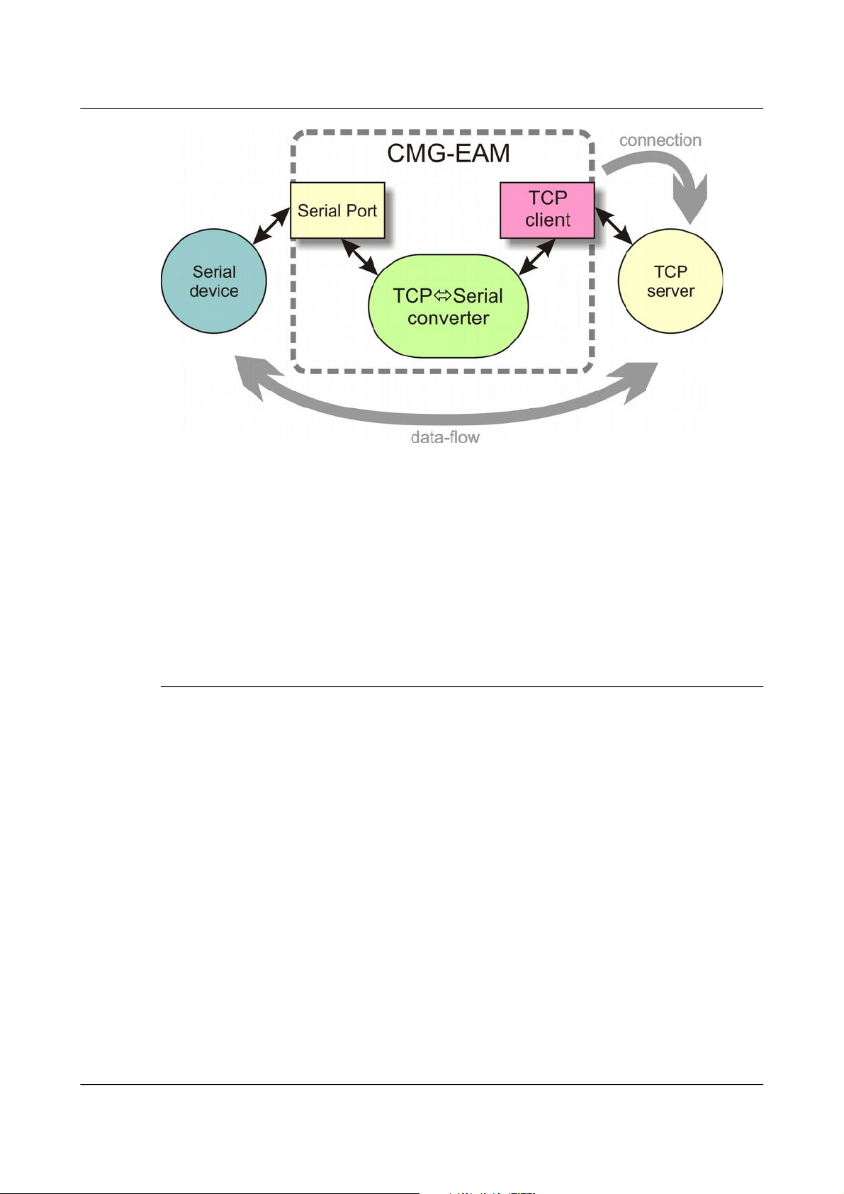
Acquisition Modules and Platinum Firmware Networking Configuration
To configure the converter from the web interface, select:
Configuration → Serial Ports
then choose the required port. Set the function to “tcp serial converter”,
select the baud rate, and save the settings. You can then use the TCP serial
converter settings button at the bottom of the page to configure the converter.
The converter's configuration page allows you to choose the mode at the top
(“Operation mode”). The other options on the page are only required in
certain modes; see below for which modes require which options.
7.8.1 Simple server mode
In Simple server mode, the converter opens the serial port and creates a TCP
server socket. Whenever a client connects to the socket, the converter reads
raw data from the serial port and writes it to the client, and reads raw data
from the client and writes it to the serial port. The serial port hardware
control lines cannot be read or altered in this mode.
Simple server mode has two relevant options: the list of addresses to listen to,
and an optional list of addresses to filter. The server can listen on multiple
simultaneous local ports and addresses (although only one client can be
active at a time).
The “Bind host” option is usually left blank. If specified, it is the name or IP
address on which this server socket will listen. For example, if you specify
“localhost” here, then this socket will only listen for incoming connections on
the loopback address, and not on the external Ethernet port. Leave it blank to
listen to all addresses.
The “Bind service” option must be specified. It is the TCP port number
(1-65535) or service name (such as “tcpserial”) for the socket. This can be
MAN-EAM-0003 98 Issue E - February 2014
Page 99

Acquisition Modules and Platinum Firmware Networking Configuration
anything you choose, although we recommend that you use the names
tcpserial, tcpserial1, tcpserial2 and so on through to tcpserial15,
which are pre-defined to correspond to port numbers 10002, 10003, through
to 10017.
The mapping from port names to port numbers is configured by the
conventional Linux file /etc/services which can be edited from the
command line if required.
If desired, you can configure a list of addresses from which to accept
connections. If no addresses are configured, then all incoming addresses will
be accepted. Otherwise, connections will only be accepted if they match an
entry in the table with its Reject box unticked. Entries are matched in order;
as soon as a match is made, the connection is accepted or rejected, and no
further processing is done.
The “IP addresses” fields can each specify a host name, an IP address or an IP
address range (given in CIDR format). For example, to accept connections
from LAN addresses, you can add the addresses:
• 10.0.0.0/8
(anything from 10.0.0.0 to 10.255.255.255);
• 172.16.0.0/12
(anything from 172.16.0.0 to 172.31.255.255);
• 192.168.0.0/16
(anything from 192.168.0.0 to 192.168.255.255); and
• 127.0.0.1
(loopback address).
7.8.2 Simple client mode
This mode of operation is similar to simple server, except that the acquisition
module establishes an outgoing TCP client connection rather than listening
on a socket. It writes raw data from the serial port to the remote server, and
writes raw data from the remote server to the serial port. It does not support
the querying or setting of the serial port hardware control lines.
In this mode, only a single option needs to be provided: the contact details for
the remote server (IP address and port). The format of this option is
“host,service”. The host may be a hostname or an IP address. The service
may be a TCP port number or a service name from /etc/services.
MAN-EAM-0003 99 Issue E - February 2014
Page 100

Acquisition Modules and Platinum Firmware Digitiser Configuration
8 Digitiser Configuration
8.1 Configuring digitisers using the web interface
The configuration interface can be used to configure the digitiser module in a
DAS or any serially attached Güralp digitiser, such as CMG-DM24 or
CMG-CD24. The internal digitiser module in a CMG-DAS is, effectively,
serially connected so both internal and external digitisers are handled
identically.
To configure a digitiser using the web interface select:
Configuration → Instruments → Port A instrument....
The list alters dynamically to reflect the system's embedded and attached
devices. For every digitiser detected, an entry appears which allows you to
configure the digitiser.
The information shown on this screen is retrieved from the digitiser using a
sequence of background commands over a serial communications line and
may, therefore, take a few seconds to display. A progress indicator is
displayed during this process. It is possible to display this sequence of
commands (together with the responses received from the digitiser) and this
may be useful both for learning the command-line interface of the digitiser
and for debugging any unexpected behaviour. To do this, select “Show full
digitiser dialogue in future form submissions” from the miscellaneous section
near the bottom of the configuration screen.
8.1.1 Configurable parameters
The digitiser configuration screen is too large to be reproduced in one
illustration in this manual. It is, therefore, shown here in sections.
MAN-EAM-0003 100 Issue E - February 2014
Note: To control (as opposed to configure) the digitiser and its
attached instrument (sensor locking, mass centring, etc.) see section
14.3.2 on page 224.
Note: This is a web form and, therefore, no changes will be made to
the actual configuration of the digitiser until the form is submitted –
i.e. until the operator scrolls to the bottom of the page and clicks
.
 Loading...