

Page 1

CMG-CD24S6EAM
Technical Manual
Document No. MAN-C24-0003
Designed and manufactured by
Guralp Systems Limited
3 Midas House, Calleva Park
Aldermaston RG7 8EA
England
Proprietary Notice: The information in this manual is
proprietary to Guralp Systems Limited and may not be copied
or distributed outside the approved recipient's organisation
without the approval of Guralp Systems Limited. Guralp
Systems Limited shall not be liable for technical or editorial
errors or omissions made herein, nor for incidental or
consequential damages resulting from the furnishing,
performance, or usage of this material.
Issue A May 2011
Page 2

CMG-CD24S6EAM Contents
Table of Contents
1 Prelims............................................................................................................................... 1
1.1 Proprietary Notice...................................................................................................... 1
1.2 Cautions and Notes.................................................................................................... 1
1.3 Manuals and Software................................................................................................ 1
1.4 Conventions................................................................................................................ 1
2 Introduction.......................................................................................................................2
2.1 Equipment Overview.................................................................................................2
2.2 Ports............................................................................................................................ 2
2.2.1 External Ports...................................................................................................... 2
2.2.2 Internal Ports....................................................................................................... 4
2.3 System Architecture................................................................................................... 5
2.3.1 Acquisition units................................................................................................. 5
2.3.2 Example sensor station....................................................................................... 6
3 Setting up the CMG-CD24S6EAM ................................................................................... 7
3.1 Initial Installation.......................................................................................................7
3.2 Connecting to the Lantronix WiPort NR....................................................................7
3.3 Connecting to the CMG-EAM.................................................................................... 8
3.4 Using the internal mass storage device...................................................................10
3.5 Warning and error reporting.................................................................................... 11
3.5.1 Configurable parameters in simple mode........................................................ 11
3.5.2 Configurable parameters in expert mode.........................................................12
4 Appendices...................................................................................................................... 13
4.1 Appendix A - Default Settings.................................................................................13
4.1.1 Lantronix WiPort NR Default Settings............................................................. 13
4.1.2 Lantronix WiPort NR Default Settings Screenshots.........................................14
4.1.3 EAM Fast Port Default Settings........................................................................ 17
4.1.4 EAM Fast Port Default Settings Screenshots....................................................18
4.2 Appendix B - Lantronix WiPort NR Device Manager..............................................20
4.3 Appendix C - Advanced network configuration......................................................23
4.3.1 Accessing the configuration menu via the serial Interface..............................23
4.3.2 Configuring the network interfaces..................................................................24
4.3.3 Configuring the Ethernet port...........................................................................24
4.4 Appendix D - Using terminal emulators..................................................................26
4.4.1 Hyperterminal, as provided with Windows XP...............................................26
4.4.2 Using Hyperterminal with Windows Vista or Windows 7..............................28
4.4.3 Using PuTTY.................................................................................................... 28
4.5 Appendix E - Connector pinouts.............................................................................31
MAN-C24-0003 Issue A - May 2011
Page 3

CMG-CD24S6EAM Contents
4.5.1 SENSOR A & B.................................................................................................. 31
4.5.2 GPIO.................................................................................................................. 32
4.5.3 GPS.................................................................................................................... 33
4.5.4 USB.................................................................................................................... 34
4.5.5 Ethernet............................................................................................................. 35
4.5.6 Power/Data Out................................................................................................. 36
4.5.7 Lantronix WiPort NR D-Connector...................................................................37
4.6 Appendix F - Specifications.....................................................................................38
4.7 Appendix G - Revision history................................................................................. 39
MAN-C24-0003 Issue A - May 2011
Page 4
CMG-CD24S6EAM Prelims
1 Prelims
1.1 Proprietary Notice
The information in this Manual is proprietary to Guralp Systems Limited and
may not be copied or distributed outside the approved recipient’s organisation
without the approval of Guralp Systems Limited.
Guralp Systems Limited shall not be liable for technical or editorial errors or
omissions made herein; nor for incidental or consequential damages resulting
from the furnishing, performance, or use of this material.
1.2 Cautions and Notes
Cautions and notes are displayed and defined as follows:
Caution: A triangle or cautionary symbol indicates a chance of
damage to or failure of the equipment if the caution is not heeded.
Note: A circle indicates indicates a procedural or advisory note.
1.3 Manuals and Software
All manuals and software referred to in this document are available from the
Guralp Systems website: www.guralp.com unless otherwise stated.
1.4 Conventions
Throughout this manual, examples are given of command-line interactions.
In these examples, a fixed-width typeface will be used:
Example of the fixed-width typeface used.
Commands that you are required to type will be shown in bold:
Example of the fixed-width, bold-face typeface.
Where data that you type may vary depending on your individual
configuration, such as parameters to commands, these data are additionally
shown in italics:
Example of the fixed-width, bold-faced, italic
typeface.
Putting these together into a single example:
System prompt: user input with variable parameters
MAN-C24-0003 1 Issue A - May 2011
Page 5
CMG-CD24S6EAM Introduction
2 Introduction
2.1 Equipment Overview
The Guralp Systems CMG-CD24S6EAM is an acquisition unit providing a
guaranteed 100ms low-latency Ethernet output with full system redundancy.
Inside each acquisition unit are a pair of CMG-CD24 digitisers, a Lantronix
Wi-port NR Ethernet module and a CMG-EAM communication and control
module.
The CMG-CD24 is an analogue to digital converter that receives signals from
connected seismometers and other devices and feeds the digital output to both
the Lantronix Wi-port NR and a CMG-EAM modules. The Lantronix
Wi-port NR provides a guaranteed 100ms low latency Ethernet output and the
EAM provides Ethernet and serial outputs.
GPS timing is used throughout, there is an internal mass storage device and
protection is provided through GPS and Network surge protectors.
On the front of the acquisition unit is an LCD display which cycles though a
series of status messages such as the IP address and GPS status.
The system architecture is given in section 2.3 on page 5.
2.2 Ports
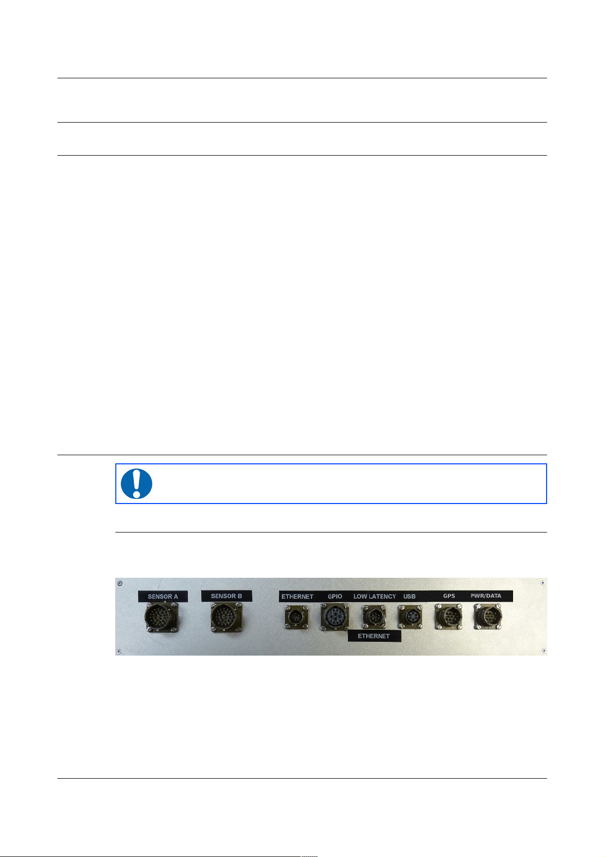
2.2.1 External Ports
There are 8 ports on the back of the acquisition unit. These are described
below.
Note: Refer to Appendix E on page 31 for information on connector
pinouts.
2.2.1.1 Sensor A and Sensor B
Two 26-pin connectors that provide power to the instruments and accept
analogue signals from connected sensors.
MAN-C24-0003 2 Issue A - May 2011
Page 6

CMG-CD24S6EAM Introduction
2.2.1.2 ETHERNET
The two 6-pin 100BASE-TX Ethernet ports support connection to a hub,
switch or router. The low-latency port connects to the Lantronix WiPort NR
device and the other connects to the CMG-EAM.
2.2.1.3 GPIO
The 12-pin GPIO (General Purpose Input/Output) port fulfils three functions:
it provides a serial console to the EAM, which can be used for monitoring,
configuration and control; it provides USB access from a PC or laptop to the
internal mass storage device for data collection and it provides a number of
tri-state lines which can be used to control or monitor external equipment.
One application is as tamper detection lines, which can be connected to
external switches and monitors as part of a secure installation.
2.2.1.4 USB
The 6-pin USB port allows connection of an external USB storage device for
data collection. It is also possible to perform firmware upgrades using this
port in situations where internet access is not available.
2.2.1.5 GPS
The 10-pin GPS port connects to a Guralp Systems GPS receiver which acts as
a timing source for time-stamping seismic data.
2.2.1.6 PWR/DATA
The 10-pin Power/Data Out port is the power input and general-purpose serial
port. It is a command line terminal running at 115,200 Baud in the default
configuration but it can also be used for GCF output, PPP network
connections, inbound GCF (from a digital instrument, for example), NMEA
functions, TCP serial conversion, a modem answering service or as a recorder
to store and forward data from any instrument with a serial output.
MAN-C24-0003 3 Issue A - May 2011
Page 7
CMG-CD24S6EAM Introduction
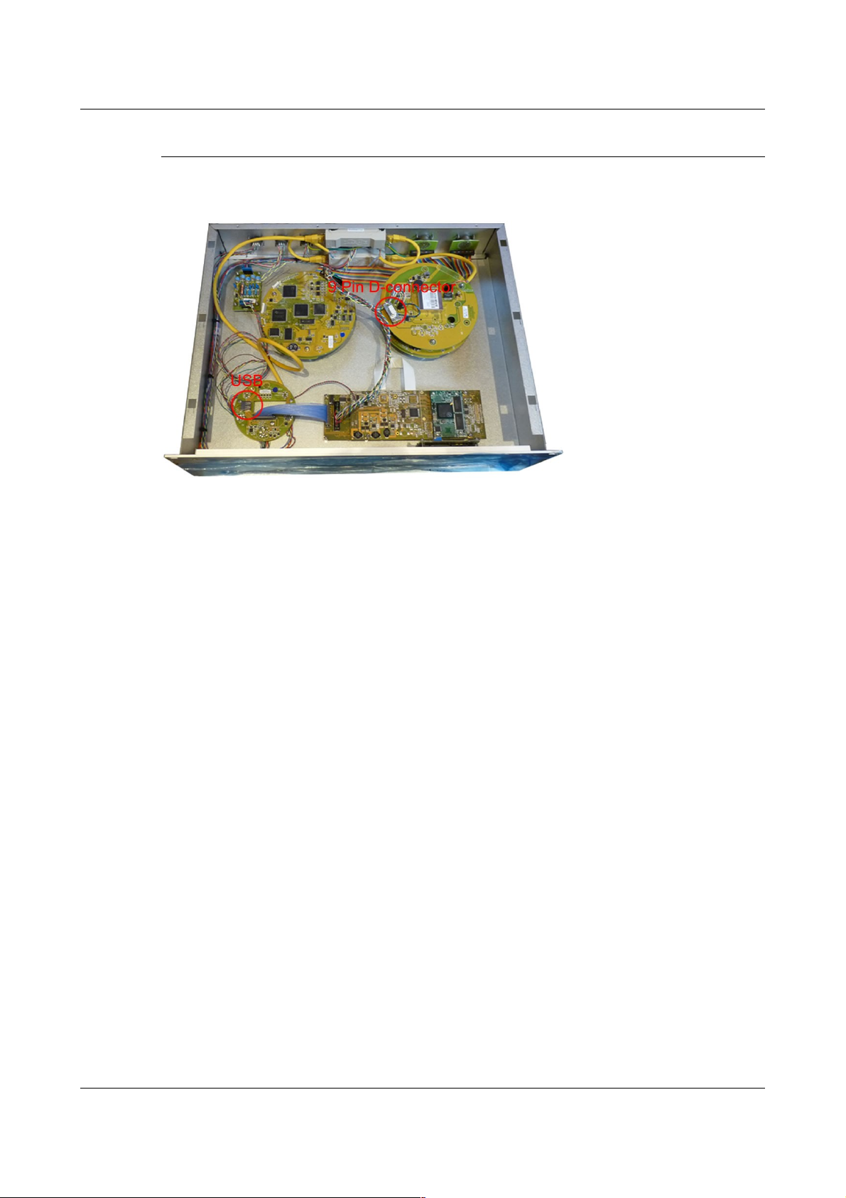
2.2.2 Internal Ports
There are two internal ports that can be accessed by removing the top cover
from the acquisition unit. These are described below.
2.2.2.1 USB
The internal USB connector allows for the installation of a suitable mass
storage device. An 8Gb mass storage device is supplied as standard and can
be upgraded if required.
2.2.2.2 D-connector
The 9-pin D connector provides RS232 access to the Lantronix WiPort NR
device for advanced configuration (see Appendix C on page 23).
MAN-C24-0003 4 Issue A - May 2011
Page 8
CMG-CD24S6EAM Introduction
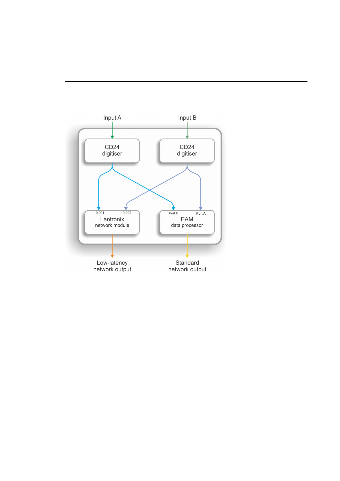
2.3 System Architecture
2.3.1 Acquisition units
The primary system architecture of the acquisition units are given in the
figure below. Not all input and output ports are shown, these are listed in
section 2.2 on page 2.
The A and B inputs are analogue signals from attached seismometers as
shown in the next section.
Configuration and control of the Lantronix Wi-port NR and a CMG-EAM
modules is carried out via the web interfaces as detailed in section 3 on page
7.
Configuration and control of the digitisers is carried out via the EAM web
interface. The EAM also provides power to the CD24 digitisers.
For more information on the internal devices refer to the following manuals
available from the Guralp Systems website: www.guralp.com
MAN-EAM-0003 for the CMG-EAM
MAN-C24-0001 for the CD24
For more information on the Lantronix WiPort NR refer to the manufacturers
documentation:
www.lantronix.com/pdf/WiPort-NR_UG.pdf
MAN-C24-0003 5 Issue A - May 2011
Page 9
CMG-CD24S6EAM Introduction
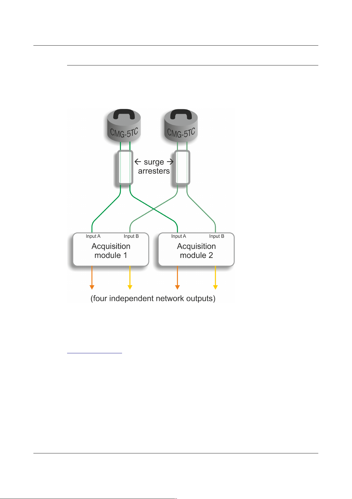
2.3.2 Example sensor station
An example of a complete sensor station is shown in the figure below. The
dual outputs from each CMG-5TC sensor are split as shown, each feeding an
acquisition unit. In this arrangement there is a duplex system with full
redundancy from the sensor to the network outputs.
The supplied instruments are standard CMG-5TC accelerometers that have
been configured so that all outputs are low gain.
For more information on the instruments refer to the CMG-5TC manual
(MAN-050-0004) available from the Guralp Systems website:
www.guralp.com.
MAN-C24-0003 6 Issue A - May 2011
Page 10

CMG-CD24S6EAM Setting up the CMG-CD24S6EAM
3 Setting up the CMG-CD24S6EAM
3.1 Initial Installation
Note: Refer to Appendix E on page 31 for information on connector
pinouts.
1. Connect the 10-pin connector on the unit to a GPS receiver using the
GPS cable. Position the GPS so that it has a good view of the sky. If you
do not have a view of the sky, you can operate the unit without a GPS
receiver, but timing information may be inaccurate.
2. Connect the instruments to the surge arrestors.
3. Connect the surge arrestors to to the 26-pin connectors in the
configuration shown in section 2.3.2 on page 6.
4. Use the power cable to connect the 10-pin Power/Data Out connector to a
fused 10 – 28 V power source and wait for the system to boot. This can
take up to 90 seconds. The LCD display will indicate when the process
is complete.
5. The system is now fully operational and will already be producing data.
6. The acquisition units can be connected to a PC using a serial cable from
the 10-pin Power/Data Out port or over a network using the Ethernet
ports.
7. Data outputs from the EAM can be viewed using the Guralp Systems
Scream application. See the manual MAN-SWA-0001 for information on
using Scream.
Data outputs from the Lantronix WiPort NR can now be accessed using
suitable software.
3.2 Connecting to the Lantronix WiPort NR
The Lantronix WiPort NR has been pre-configured so there should be no
reason to change any of the settings. If however you wish to make any
changes the following procedure for connecting to the Lantronix WiPort NR
should be used:
1. Connect the acquisition unit to a DHCP enabled network and note the IP
address.
2. Enter the IP address into the address bar of an internet browser.
MAN-C24-0003 7 Issue A - May 2011
Page 11
CMG-CD24S6EAM Setting up the CMG-CD24S6EAM
3. When the Authentication Required window displays enter a User Name
of 'admin'. Leave the password blank. Click on OK or press the Enter
key.
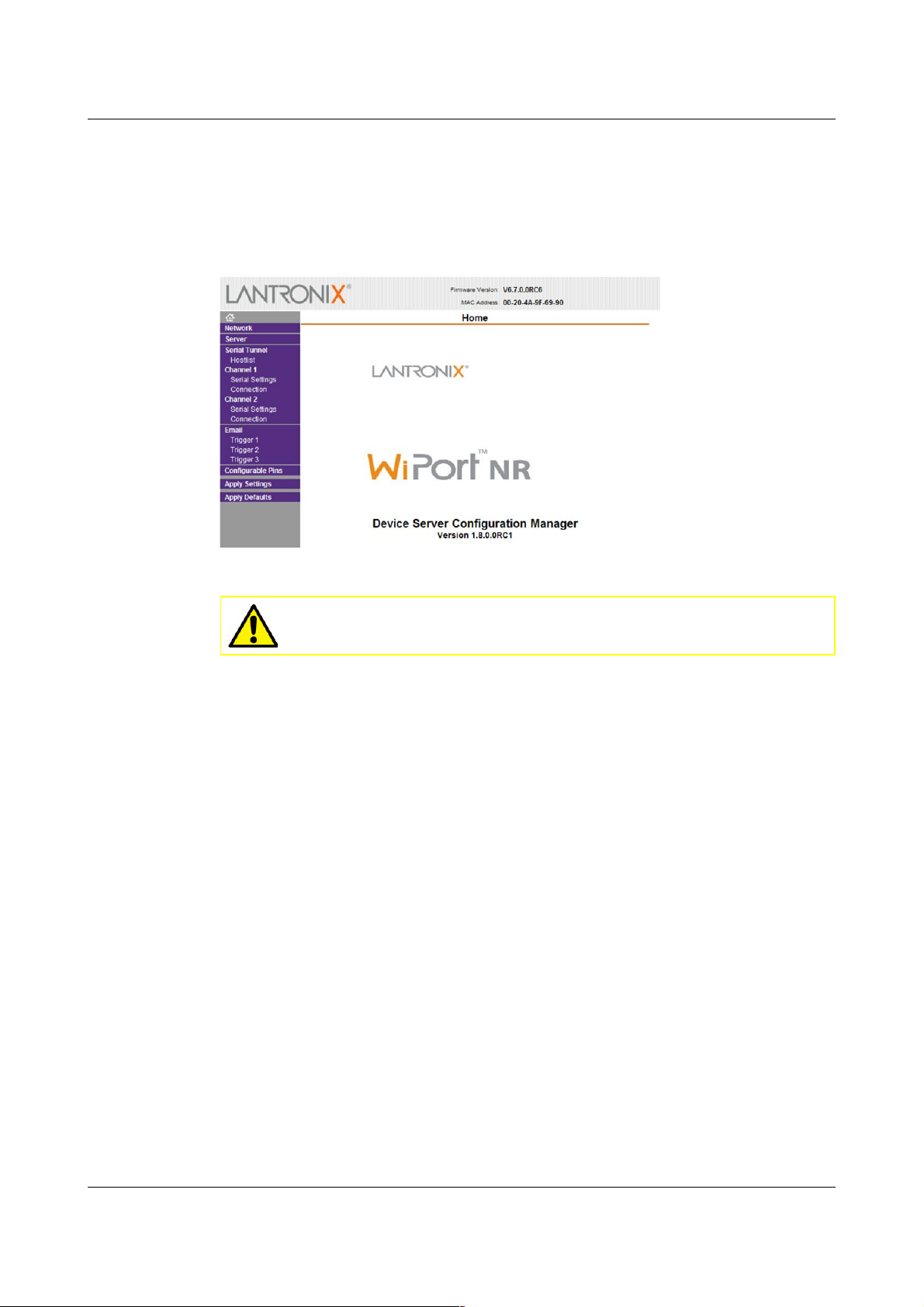
4. Once the Lantronix WiPort NR home page appears you can use the menu
list on the left to view and configure the settings:
5. The default settings for the device are given in Appendix A on page 13.
Caution: Making any changes to the default settings may
cause the device to stop working.
6. After making any changes click OK at the bottom of each screen. On
completion click on Apply Settings. This will update and reboot the
module.
If you are unable to locate the device or have problems connecting, further
information is given at Appendix B on page 20.
3.3 Connecting to the CMG-EAM
The CMG-EAM has been pre-configured so there should be no reason to
change any of the settings. If however you wish to make any changes to the
Low Latency ports the following procedure for connecting to the CMG-EAM
should be used:
1. Connect the acquisition unit to a DHCP enabled network and note the IP
address.
2. Enter the IP address into the address bar of an internet browser.
3. At the EAM homepage click on the User Login link in the menu on the
left.
4. When the Authentication Required window displays enter a User Name
of 'root' and a password of 'rootme'. Click on OK or press the Enter key.
MAN-C24-0003 8 Issue A - May 2011
Page 12
CMG-CD24S6EAM Setting up the CMG-CD24S6EAM
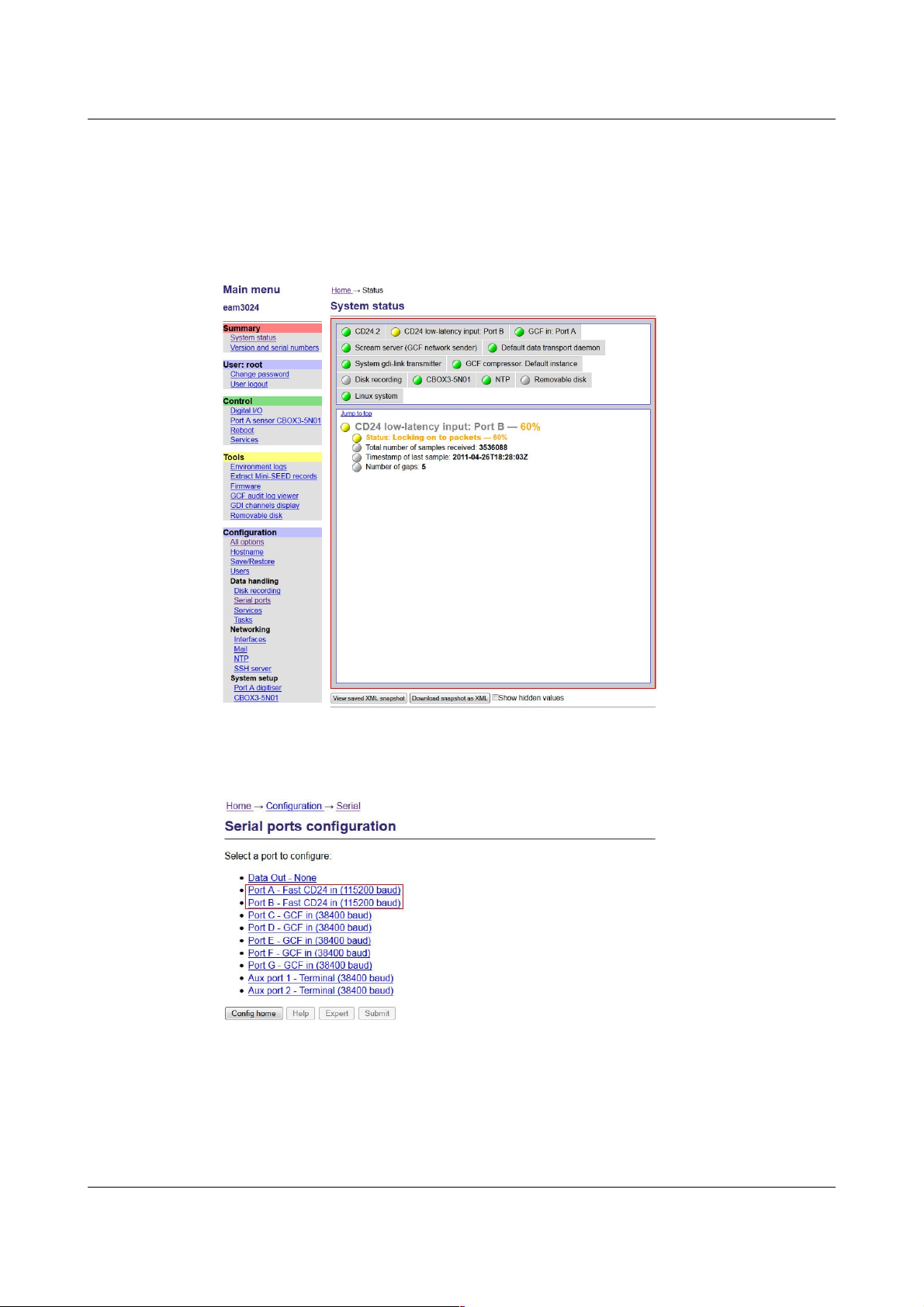
5. Once the full menu appears on the left you have access to all the
configuration and control options.
The right hand part of the widow displays the current status of the
system. The links in the main menu will update the main part of the
window to the selected configuration and control settings:
6. To see the settings for the low-latency ports first click on the Serial Ports
link in the main menu then select Port A or Port B from the list that
appears:
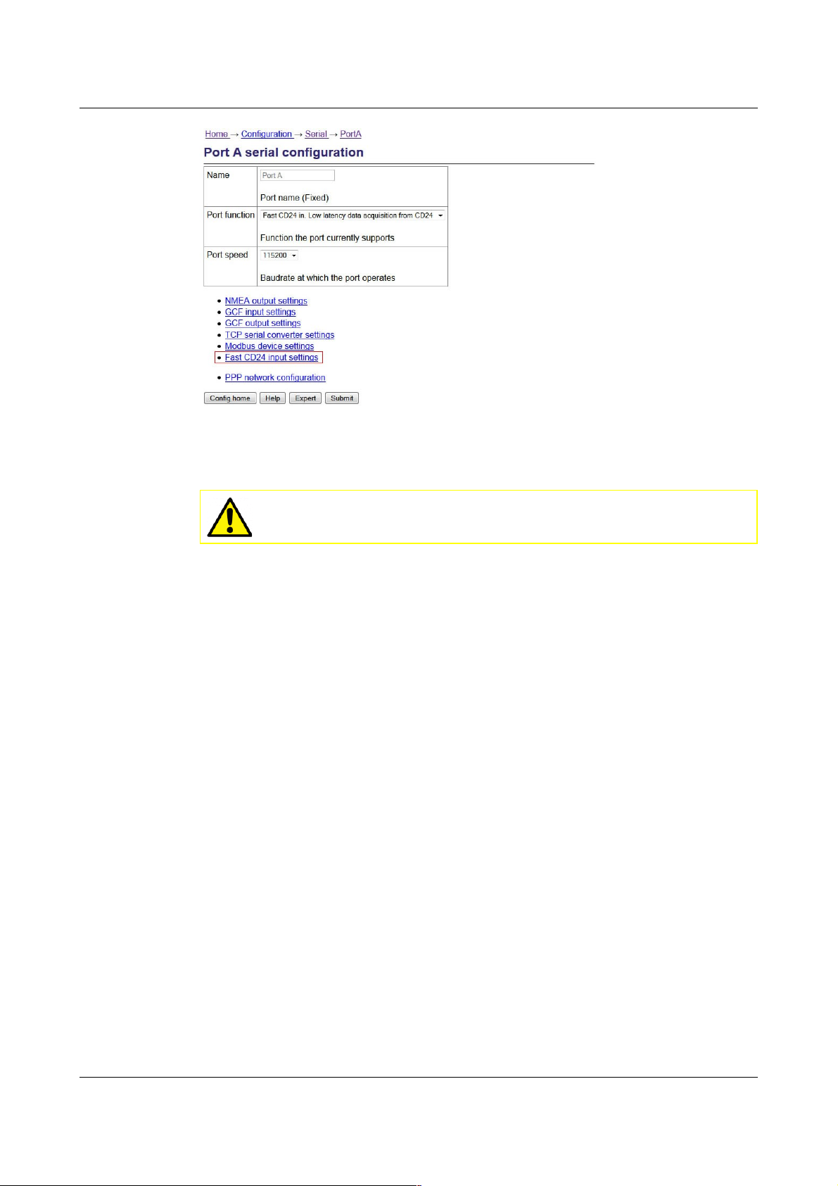
7. From the port A or B serial configuration page click on the Fast CD24
input settings link:
MAN-C24-0003 9 Issue A - May 2011
Page 13
CMG-CD24S6EAM Setting up the CMG-CD24S6EAM
8. The 5 tabs that appear allow you to the view and change the port
settings. The default settings for the ports are given in Appendix A on
page 13.
Caution: Making any changes to the default settings may
cause the device to stop working.
9. After making any changes click on the Submit button at the bottom of
each screen.
If you are unable to locate the device or have problems connecting, further
information is given in the EAM manual: MAN-EAM-0003.
Other menu items in the EAM allow for their control and configuration of the
CMG-CD24 digitisers, ports and other connected devices.
Any changes made in the EAM to the CD24 settings will be reflected in the
Lantronix WiPort NR data output.
3.4 Using the internal mass storage device
The acquisition unit has an internal mass storage device which is accessible
via the GPIO port (see section 2.2.1.3 on page 3).
To write to the internal mass storage device:
1. Connect to the CMG-EAM as described in section 3.3 on page 8.
2. Click on the Disc Recording link in the main menu.
3. Select Internal USB storage from the Recording destination drop-down
menu.
When a USB host, such as a laptop or PC, is connected to the GPIO port,
internal circuitry detects the USB power and automatically connects the Flash
MAN-C24-0003 10 Issue A - May 2011
Page 14
CMG-CD24S6EAM Setting up the CMG-CD24S6EAM
memory to the GPIO socket, causing it to behave identically to a standard USB
memory stick.
When no power is detected at the GPIO port, the Flash memory is available to
the system as if it were a standard removable mass storage device. All of the
mass storage device recording options described in the CMG-EAM manual
MAN-EAM-0003.
3.5 Warning and error reporting
Each component in the station has a predefined warning and error level. The
status of the components are indicated on the EAM homepage.
Green indicators are shown when the level is above 70%
Amber warnings are displayed when the level falls below 70%
Red errors are displayed when the level falls below 40%
The status of all components can be monitored and if the level falls below a
set percentage a selected output line can be switched from low to high for use
by an external indication system.
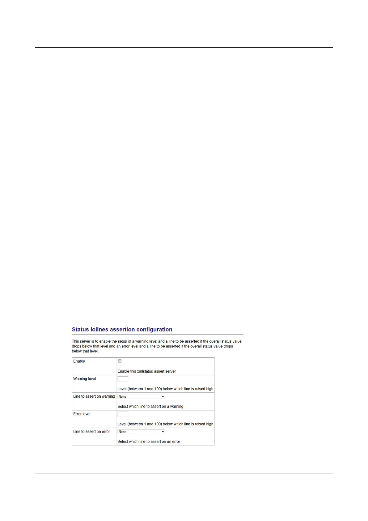
To configure the status iolines using the web interface select:
Configuration > All options > Status iolines assertion configuration
To configure the status iolines from the command line, start gconfig and select
“Status iolines assertion configuration” from the top level menu.
3.5.1 Configurable parameters in simple mode
The configurable parameters for recording data in simple mode are shown
below:
Enable: Activates the status iolines assertion server.
MAN-C24-0003 11 Issue A - May 2011
Page 15

CMG-CD24S6EAM Setting up the CMG-CD24S6EAM
Warning level: Set the level at which the warning signal is to be triggered.
Line to assert on warning: Select the output line from the dropdown list. All
output lines are displayed so care should be taken to choose a suitable output
line.
Error level: Set the level at which the warning signal is to be triggered. The
error level must be less than the warning level.
Line to assert on error: Select the output line from the dropdown list. All
output lines are displayed so care should be taken to choose a suitable output
line.
3.5.2 Configurable parameters in expert mode
An additional field is displayed in expert mode:
Log level: The drop-down menu controls the level of detail present in log
messages. Not all of the standard syslog logging levels are available. The
menu offers a choice (in order of decreasing detail) of:
• Debugging information
• Informational messages
• Important notices
• Warnings
MAN-C24-0003 12 Issue A - May 2011
Page 16

CMG-CD24S6EAM Appendices
4 Appendices
4.1 Appendix A - Default Settings
4.1.1 Lantronix WiPort NR Default Settings
Parameter Setting
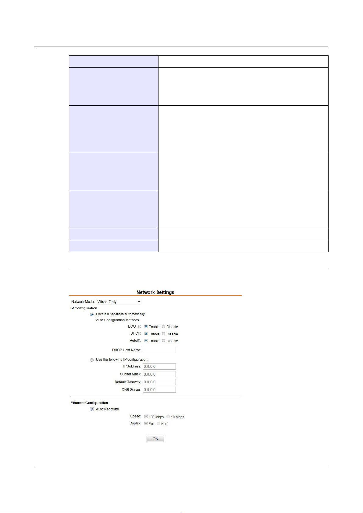
Network
Network mode Wired Only
IP Configuration Obtain IP address automatically
Ethernet Configuration Auto Negotiate
Server
Server Configuration
Advanced
Hostlist
Retry Settings
Host Information All set to zero
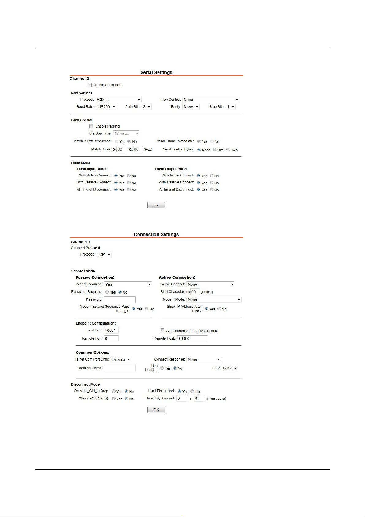
Channel 1 and 2 Serial Settings
Disable Serial Port Leave un-ticked
Port Settings
Passwords: Leave blank
ARP Cache Timeout: 600 seconds
TCP Keepalive: 45 seconds
Monitor Mode @ Bootup: Enable
CPU Performance Mode: Regular
HTTP Server Port: 80
0x77FE Server Port: 30718
MTU Size: 1400
Retry Counter: 3
Retry Timeout: 250
Protocol: RS232
Baud Rate:115200
Data Bits: 8
Flow Control: None
Parity: None
Stopbits: 1
Pack Control
Flush Mode
Channel 1 and 2 Connection Settings
Connection Protocol TCP
Connect Mode
MAN-C24-0003 13 Issue A - May 2011
Enable Packing: leave un-ticked
All set to No
Accept Incoming: Yes
Password required: No
Page 17
CMG-CD24S6EAM Appendices
Parameter Setting
Modem Escape Sequence Pass Through: Yes
Active connect: None
Modem Mode: None
Show IP Address After RING: Yes
Endpoint Configuration
Common options
Disconnect Mode
Email
Configurable Pin Settings
Local Port: 10001 for Channel 1
10002 for Channel 2
Remote Port: 0
Auto increment for active connect: NA
RemoteHost: 0.0.0.0
Telnet Com Port Cntrl: Disable
Terminal Name: NA
Connect Response: None
Use Hostlist: No
On Mdm_Ctrl_In Drop: No
Check EOT(Ctrl-D): No
Hard Disconnect: Yes
Inactivity Timeout: 0 : 0
NA
NA
4.1.2 Lantronix WiPort NR Default Settings Screenshots
4.1.2.1 Network settings
MAN-C24-0003 14 Issue A - May 2011
Page 18

CMG-CD24S6EAM Appendices
4.1.2.2 Server settings
4.1.2.3 Hostlist settings
MAN-C24-0003 15 Issue A - May 2011
Page 19
CMG-CD24S6EAM Appendices
4.1.2.4 Serial settings
4.1.2.5 Conenction settings
MAN-C24-0003 16 Issue A - May 2011
Page 20

CMG-CD24S6EAM Appendices
4.1.3 EAM Fast Port Default Settings
Parameter Setting
Main
Station
Main channels
Mux channels Component/Instrument Type
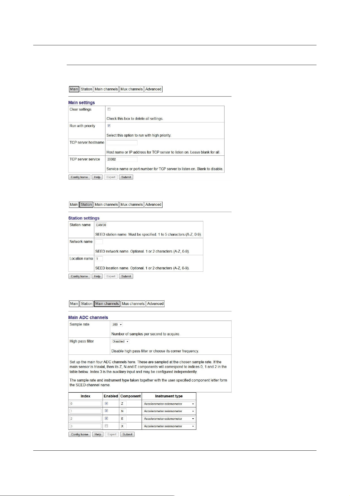
Clear settings: Leave un-ticked
Run with priority: Tick
TCP server hostname: Leave blank TCP server
service: 20002 for Port A, 20001 for Port B
Station name: Mandatory (shipped with the serial
number of the EAM).
Network name: Optional
Location name: Optional
If a common station name is used for a number of
sensors an additional location name is required to
ensure a unique identifier.
Sample Rate: 100
High pass filter: Disabled
Enabled components: Z N E
Instrument Type: Accelerometer seismometer
Z/Mass position seismometer
N/ Mass position seismometer
E/ Mass position seismometer
0/Calibration input
0/Generic electronic test point
1/Generic electronic test point
2/Generic electronic test point
3/Generic electronic test point
Advanced
MAN-C24-0003 17 Issue A - May 2011
Link delay: Leave blank
GDI Multiplexor: Default data transport daemon
Page 21
CMG-CD24S6EAM Appendices
4.1.4 EAM Fast Port Default Settings Screenshots
4.1.4.1 Main
4.1.4.2 Station
4.1.4.3 Main channels
MAN-C24-0003 18 Issue A - May 2011
Page 22

CMG-CD24S6EAM Appendices
4.1.4.4 Mux channels
4.1.4.5 Advanced
MAN-C24-0003 19 Issue A - May 2011
Page 23

CMG-CD24S6EAM Appendices
4.2 Appendix B - Lantronix WiPort NR Device Manager
The acquisition unit uses an embedded Lantronix Wi-Port module to provide
the low-latency network interface. The device can normally be accessed using
a web-interface as described in section 3.2 on page 7.
If this is not possible configuration of the interface can be carried out using
the Lantronix' DeviceInstaller utility for Microsoft Windows, using a DHCP
server or the via the serial port. You will need a PC with a network interface
installed or an RS232 connector.
Note: Refer to Appendix E on page 31 for information on connector
pinouts.
1. Download and install the DeviceInstaller utility from the Lantronix Web
site at www.lantronix.com.
DeviceInstaller requires the Microsoft .NET framework to be installed. If
you do not have this already, it can be downloaded from:
www.microsoft.com.
Note that DeviceInstaller will not work through routers or across the
Internet. All the devices need to be on the same network segment as the
PC.
2. Find out the MAC address of the network interface. This should be
printed on a label on the case.
3. Connect the 6-pin Ethernet port to the the PC's network interface either
using a crossover Ethernet cable or through a network hub. Note that
using a hub, you can connect several CD24s to the same PC and
configure them all at the same time.
4. Use the power cable to connect the 4-pin power connector to a fused 10 –
28 V power source. A 12V DC power supply is recommended.
5. Run DeviceInstaller.
DeviceInstaller's main window has two panels, a tree on the left (with
Lantronix Devices at the top) and a table on the right.
6. The program will automatically look for Lantronix devices on all of your
computer's network interfaces. If necessary, you can narrow the
selection by clicking on an entry in the tree on the left. If the program
does not list the device, press F5 or use Device > Search from the menu
system.
MAN-C24-0003 20 Issue A - May 2011
Page 24

CMG-CD24S6EAM Appendices
7. A WiPort NR entry should appear in the table on the right, denoting that
a device has been detected.
8. If more than one WiPort NR entry appears, DeviceInstaller has detected
several devices.
9. For every detected device, the program shows the Hardware Address (i.e.
the MAC address) and the IP address it is currently using. If you are
using a wireless router with a DHCP server, or an access point connected
to a network with a DHCP server, the device will use DHCP to assign it
an address. Otherwise, a random address will be chosen automatically.
Note: Automatic random addresses all begin with 169.254. The CD24
will choose a different one every time it is power cycled or rebooted.
10. The address of the CD24 may be shown in red with the status
Unreachable. If this happens, the sensor and PC cannot communicate
because they are not on the same subnet. Click Assign IP to start the IP
configuration wizard. Follow the instructions in the wizard to set the IP
address, or configure DHCP if you are using a DHCP server. When you
have finished, press F5 or use Device > Search from the menu system to
find the sensor with its new IP address.
Note: The IP address of the digitiser must have be on the same
subnet as the computer you want to connect to. The LAN
setting on the DeviceInstaller device tree identifies the IP
address of your computer. The first three number groups
typically need to be the same on all devices (digitisers and
computer).
11. If you want to configure the CD24 to use a static IP address, use the
Assign IP wizard as above and click Search again.
MAN-C24-0003 21 Issue A - May 2011
Page 25

CMG-CD24S6EAM Appendices
12. Double-click on the entry which corresponds to the CD24 you want to
configure. The right-hand panel will change to show the current
properties of the device.
13. Switch to the Web Configuration tab and click Go to open the Web
configuration interface.
14. You can also click Use External Browser to use your own Web browser to
configure the system.
15. Follow the steps at section 3.2 on page 7.
MAN-C24-0003 22 Issue A - May 2011
Page 26

CMG-CD24S6EAM Appendices
4.3 Appendix C - Advanced network configuration
The Lantronix WiPort NR networking module has serial-accessible
configuration systems which can be used to configure them in the event that
communication over a network is lost.
If you have problems connecting to the CD24 over a network, you can access
the configuration menu over a serial link by interrupting the boot process.
See the following section for instructions. For full information about the
WiPort NR configuration options, which are used during the process, please
refer to the relevant documentation, which is available on the Lantronix Web
site: www.lantronix.com. The detailed documentation is at:
www.lantronix.com/pdf/WiPort-NR_UG.pdf
4.3.1 Accessing the configuration menu via the serial Interface
Access to the configuration menu over the serial interface can be obtained
using any serial terminal emulator (see Appendix D on page 26).
The procedure for connecting to the device is:
1. Disconnect the power supply.
2. Disconnect the sensors.
3. Remove the top cover from the acquisition unit.
4. Disconnect the 26-way IDE-connector from the digitiser as indicated in
the figure below:
5. Connect an RS232 cable between the 9-pin D-connector and a PC. See
Appendix E on page 31 for connector pinouts.
6. Open a terminal connection as described in Appendix D on page 26.
7. Hold down the key while applying power to the acquisition unit.
MAN-C24-0003 23 Issue A - May 2011
Page 27

CMG-CD24S6EAM Appendices
8. After a few seconds, a banner will appear, showing the MAC address of
the network interface, along with software and library version
information. Press the Enter key to access the set-up menu. If you do
not press a key, the system will proceed to boot normally.
4.3.2 Configuring the network interfaces
Once you have access to the networking module's configuration menu, you
can configure it with its proper settings.
During the configuration process, you are prompted, in turn, for every value in
the current section. If you are unsure at any point, pressing the Enter key will
retain the current value. Please note that many values need to be entered
using special codes. These are all documented in the relevant Lantronix
manuals.
From the main menu:
1. Each channel is configured individually. To configure either press 1
(Channel 1) or 2 (Channel 2).
2. Set the Baud Rate to 115200. This is the default baud rate for the
CD24's digital output.
3. The remaining settings can be left at their default values, which is done
by pressing Enter at each prompt until you are returned to the main
menu.
4. When you have finished setting up the module, apply the new settings
by selecting option 9 Save and Exit. The module will re-boot with the
new settings in effect.
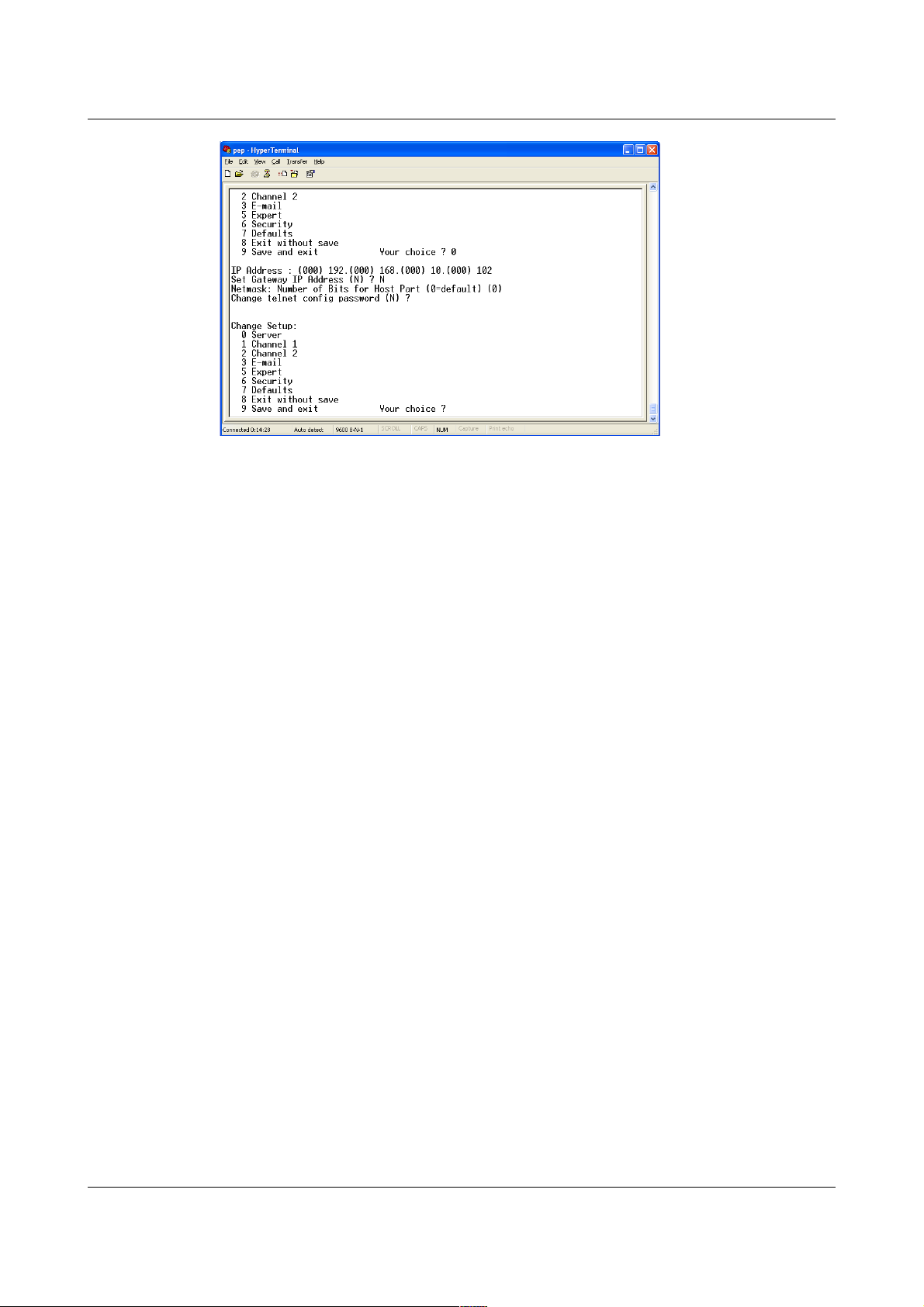
4.3.3 Configuring the Ethernet port
To configure the Ethernet port
1. If DHCP is not being used to assign IP addresses, enter the required
address manually. The IP address must be set to a unique value in the
network. Enter each octet and press Enter to move to the next octet..
The current value is displayed in parentheses. If you do wish to use
DHCP, enter 0 at each prompt (an IP address of 0.0.0.0 is used to select
DHCP operation).
MAN-C24-0003 24 Issue A - May 2011
Page 28
CMG-CD24S6EAM Appendices
2. If the digitiser is to be connected to a routed network, enter the address
of the default gateway in the same manner.
3. At the netmask prompt, enter 0 if you are using normal (classful) internet
addressing. If you have a non-standard or classless addressing scheme,
enter the number of bits of the IP address to be used for network
identification. Note that this is not the standard way of specifying
netmasks; it is more akin to the /n modifier used in CIDR address
specification.
4. When you have finished setting up the module, apply the new settings
by selecting option 9 Save and Exit. The module will re-boot with the
new settings in effect.
5. Disconnect the power supply from the acquisition unit.
6. Remove the RS232 cable from the 9-pin D-connector.
7. Connect the 26-way IDE-connector to the digitiser.
8. Install the top cover.
9. Connect the sensors to the acquisition unit.
10. Connect the power supply to the acquisition unit.
MAN-C24-0003 25 Issue A - May 2011
Page 29

CMG-CD24S6EAM Appendices
4.4 Appendix D - Using terminal emulators
There are a number of terminal emulator programs that you can use to access
the serial ports of the digitiser and networking interfaces. Three of these are
detailed below.
4.4.1 Hyperterminal, as provided with Windows XP.
1. Click on Start and then Run.
2. Enter 'hypertrm' and click on OK.
3. The program will ask you for a name for the connection:
Enter any suitable name, then click OK.
MAN-C24-0003 26 Issue A - May 2011
Page 30

CMG-CD24S6EAM Appendices
4. You will then be prompted to enter COM port and modem details:
The Country/region, Area code and Phone number fields can be ignored:
they are only used when working with modem connections. Select the
name of the correct COM port from the Connect using drop-down menu,
then click OK.
5. Enter the port configuration settings:
MAN-C24-0003 27 Issue A - May 2011
Page 31

CMG-CD24S6EAM Appendices
Ensure the following parameters are set:
Bits per second: 9600
Data bits: 8
Parity: None
Stop bits: 1
Flow control: None
6. Click on OK and the program will then connect provide you with a
terminal emulator screen, from which you can access the command line
of your system.
4.4.2 Using Hyperterminal with Windows Vista or Windows 7.
HyperTerminal is not provided with the Windows Vista or Windows 7
operating systems but the necessary files can be copied from the i386
directory of the Windows XP CD if you have one available. The two files you
will need are:
hypertrm.dll
hypertrm.exe.
If you do not have a Windows XP disc the files can be downloaded from:
www.mediafire.com
To use Hyperterminal with Windows Vista or Windows 7:
1. Copy the two files into your windows/system32 directory.
2. To access HyperTerminal, use Windows+R on your keyboard. Enter
'hypertrm' and click on OK.
3. If Windows open a security warning window click on Run. You may
also be asked if you wish to use HyperTerminal as a the default terminal
window.
4. Now follow the instructions given in section 4.4.1, above.
4.4.3 Using PuTTY.
PuTTY is a free terminal package for windows which is useful if
HyperTerminal is not available. It can be downloaded from
www.chiark.greenend.org.uk. The easiest package to use is the 'windows
installer'. Install PuTTY by following the on-screen instructions.
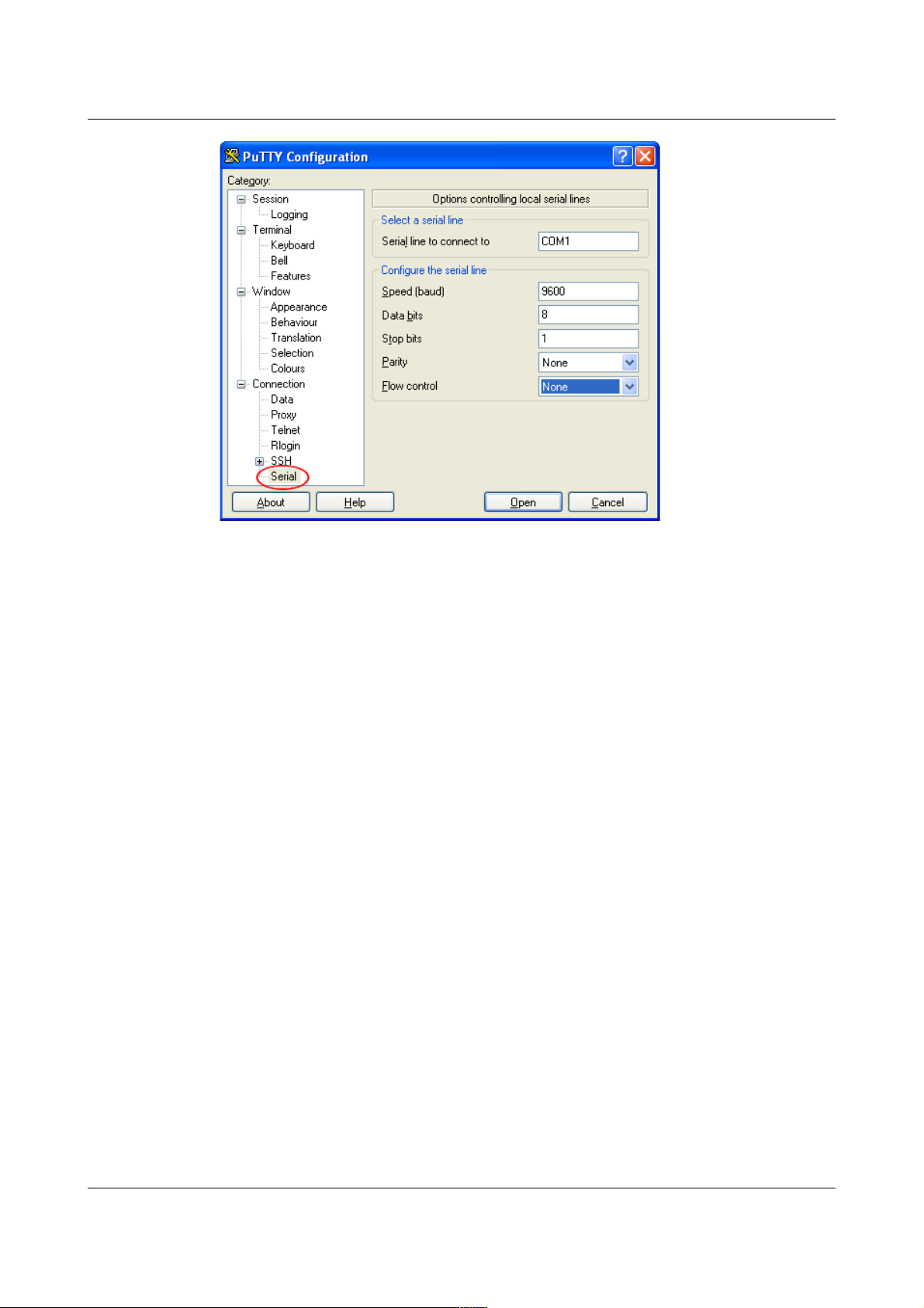
1. Start PuTTY by clicking on the desktop icon or Start-menu entry
2. Click on Serial at the bottom of the category menu on the left:
MAN-C24-0003 28 Issue A - May 2011
Page 32
CMG-CD24S6EAM Appendices
3. Select a serial line to connect to. This is usually COM1.
4. Configure the serial line with the following settings:
Speed (baud): 9600
Data bits: 8
Stop bits: 1
Parity: None
Flow control: None
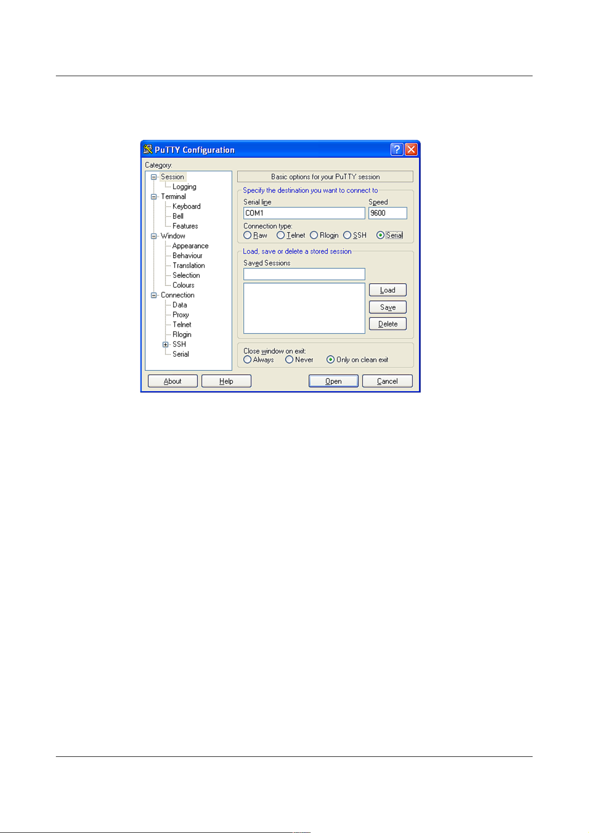
5. Click on Session in the main menu on the left.
MAN-C24-0003 29 Issue A - May 2011
Page 33
CMG-CD24S6EAM Appendices
6. In the right hand part of the window use the radio buttons to select the
Serial Connection type. Check the Serial line and Speed fields are
correct:
7. To save the settings enter a suitable session name in the Saved Sessions
field then click Save.
The next time you start PuTTY, your saved session will appear in the list
and you can simply double-click it to open a new session with the same
settings.
8. Click the Open button to start the terminal emulator.
MAN-C24-0003 30 Issue A - May 2011
Page 34
CMG-CD24S6EAM Appendices
4.5 Appendix E - Connector pinouts
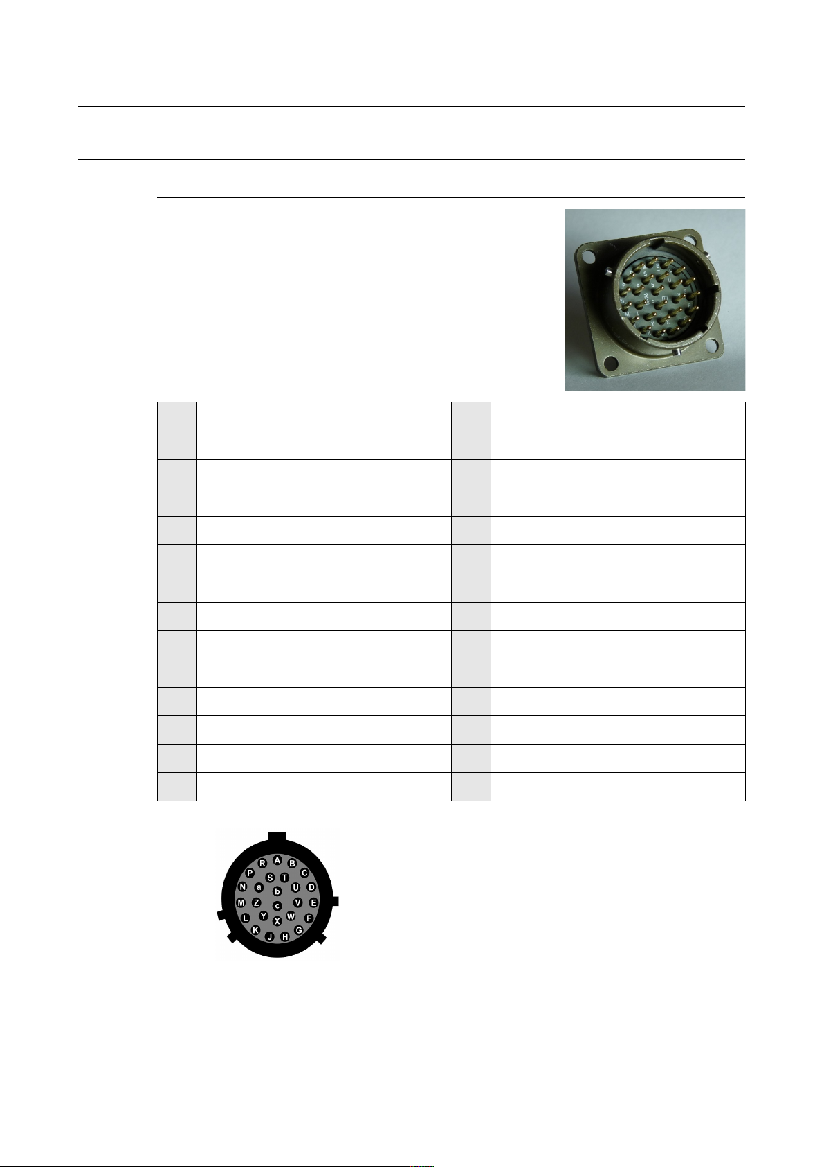
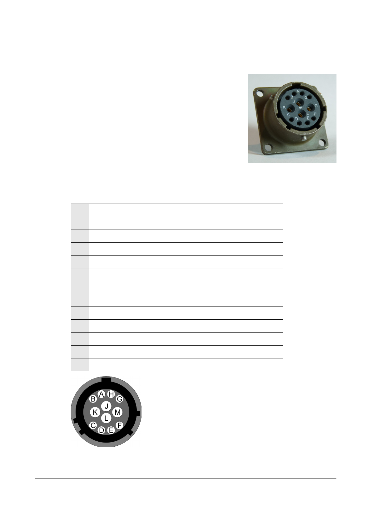
4.5.1 SENSOR A & B
This is a standard 26-pin “mil-spec” plug,
conforming to MIL-DTL-26482 (formerly
MIL-C-26482). A typical part-number is
02E-16-26P although the initial “02E” varies with
manufacturer.
Suitable mating connectors have part-numbers like
***-16-26S and are available from Amphenol, ITT
Cannon and other manufacturers.
Pin Function Pin Function
A Vertical velocity +ve P Calibration signal
B Vertical velocity –ve R Vertical calibration enable
C N/S velocity +ve S N/S calibration enable
D N/S velocity –ve T E/W calibration enable
E E/W velocity +ve U Centre
F E/W velocity –ve V Active-high
G Vertical mass position W Unlock
H not connected X Lock
J N/S mass position Y Logic signal ground
K Busy indicator LED Z not connected
L E/W mass position a not connected
M not connected b Power 0 V
N Signal ground c Power +10 to +24 V
Wiring details for the compatible socket,
***-16-26S, as seen from the cable end
(i.e. during assembly).
MAN-C24-0003 31 Issue A - May 2011
Page 35
CMG-CD24S6EAM Appendices
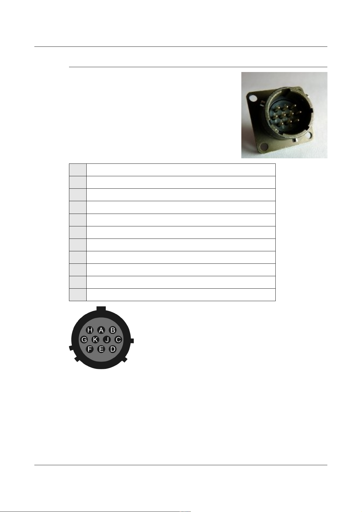
4.5.2 GPIO
These are standard 12-pin “mil-spec” sockets,
conforming to MIL-DTL-26482 (formerly
MIL-C-26482). A typical part-number is
02E-14-12S although the initial “02E” varies with
manufacturer.
Suitable mating connectors have part-numbers like
***-14-12P and are available from Amphenol, ITT
Cannon and other manufacturers.
The USB lines provide external host access to the internal USB memory
device. When power is sensed on pin J, an internal switch disconnects the
memory device from the internal circuitry and connects it to this socket.
Pin Function
A USB Data -ve (USB Type A pin 2) - see text above.
B USB Data +ve (USB Type A pin 3) - see text above.
C Anti-tamper line 4
D Anti-tamper line 3
E Anti-tamper line 2
F Anti-tamper line 1
G Console transmit (RS232 TXD)
H Console receive (RS232 RXD)
J USB Power input (USB Type A pin 1) - see text above.
K Ground (USB Type A pin 4)
L Anti-tamper line 0
M Ground
Wiring details for the compatible plug, ***-14-12P,
as seen from the cable end (i.e. during assembly).
MAN-C24-0003 32 Issue A - May 2011
Page 36

CMG-CD24S6EAM Appendices
4.5.3 GPS
This is a standard 10-pin “mil-spec” plug,
conforming to MIL-DTL-26482 (formerly
MIL-C-26482). A typical part-number is
02E-12-10P although the initial “02E” varies with
manufacturer.
Suitable mating connectors have part-numbers like
***-12-10S and are available from Amphenol, ITT
Cannon and other manufacturers.
Pin Function
A Power 0 V
B Power +12 V
C 1pps signal
D not connected
E Digitizer console transmit
F Digitizer console receive
G RS232 ground
H Digitizer console ground
J RS232 transmit to GPS
K RS232 receive from GPS
Wiring details for the compatible socket, ***-12-10S,
as seen from the cable end (i.e. during assembly).
MAN-C24-0003 33 Issue A - May 2011
Page 37

CMG-CD24S6EAM Appendices
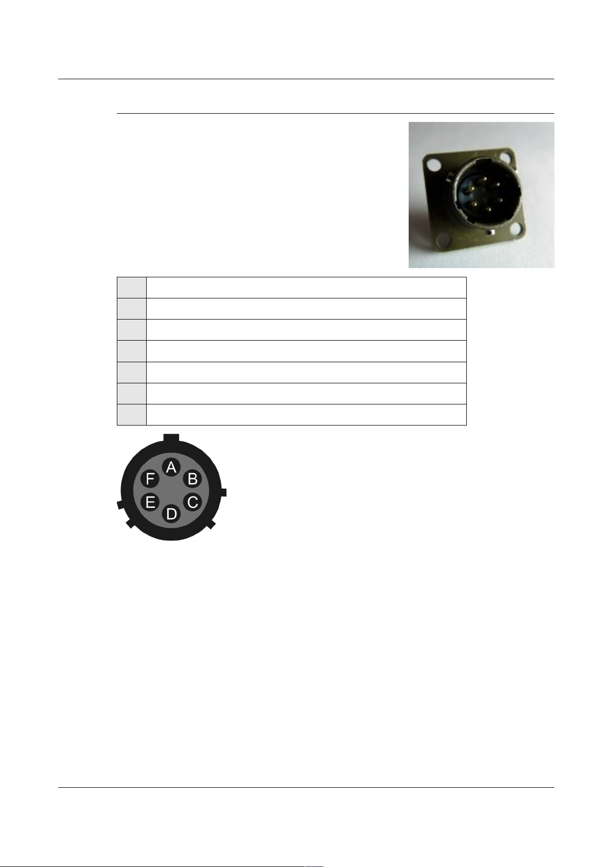
4.5.4 USB
This is a standard 6-pin “mil-spec” socket,
conforming to MIL-DTL-26482 (formerly
MIL-C-26482). A typical part-number is
02E-10-06S although the initial “02E” varies with
manufacturer.
Suitable mating connectors have part-numbers like
***-10-06P and are available from Amphenol, ITT
Cannon and other manufacturers.
Pin Function
A +5 V DC (USB Type A pin 1)
B Data –ve (USB Type A pin 2)
C Data +ve (USB Type A pin 3)
D 0 V (USB Type A pin 4)
E Shielding
F not connected
Wiring details for the compatible plug, ***-10-06P,
as seen from the cable end (i.e. during assembly).
MAN-C24-0003 34 Issue A - May 2011
Page 38
CMG-CD24S6EAM Appendices
4.5.5 Ethernet
This is a standard 6-pin “mil-spec” plug,
conforming to MIL-DTL-26482 (formerly
MIL-C-26482). A typical part-number is
02E-10-06P although the initial “02E” varies with
manufacturer.
Suitable mating connectors have part-numbers like
***-10-06S and are available from Amphenol, ITT
Cannon and other manufacturers.
Pin Function
A Ground
B Data transmit +ve (RJ45 pin 1)
C Data receive +ve (RJ45 pin 3)
D not connected
E Data receive –ve (RJ45 pin 6)
F Data transmit –ve (RJ45 pin 2)
Wiring details for the compatible socket,
***-10-06S, as seen from the cable end (i.e.
during assembly).
MAN-C24-0003 35 Issue A - May 2011
Page 39
CMG-CD24S6EAM Appendices
4.5.6 Power/Data Out
This is a standard 10-pin “mil-spec” plug,
conforming to MIL-DTL-26482 (formerly
MIL-C-26482). A typical part-number is
02E-12-10P although the initial “02E” varies with
manufacturer.
Suitable mating connectors have part-numbers like
***-12-10S and are available from Amphenol, ITT
Cannon and other manufacturers.
Pin Function
A Power input, 0 V
B Power input, +10 to +36 V
C RS232 CTS
D RS232 RTS
E not connected
F not connected
G RS232 ground
H not connected
J RS232 receive
K RS232 transmit
Wiring details for the compatible socket,
***-12-10S, as seen from the cable end (i.e. during
assembly).
MAN-C24-0003 36 Issue A - May 2011
Page 40
CMG-CD24S6EAM Appendices
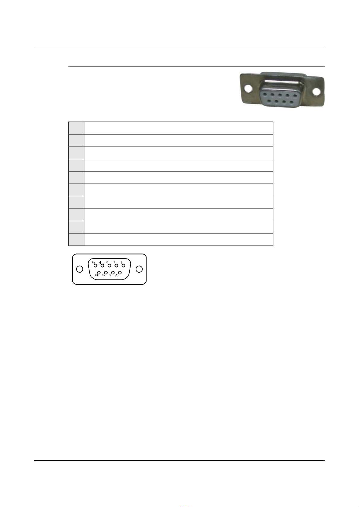
4.5.7 Lantronix WiPort NR D-Connector
These are standard DE9F (TIA-574)
sub-miniature (D-sub) line sockets, conforming to
DIN 41652 and MIL-DTL-24308. They are very
widely available, as are suitable mating
connectors.
Pin Function
1 not connected
2 RS232 transmitted data*
3 RS232 received data*
4 not connected
5 Ground
6 not connected
7 not connected
8 not connected
9 not connected
Wiring details for the compatible plug, DE9M, as
seen from the cable end (i.e. when assembling).
MAN-C24-0003 37 Issue A - May 2011
Page 41

CMG-CD24S6EAM Appendices
4.6 Appendix F - Specifications
Parameter Specification
Input range ±10V differential
Nominal Sensitivity 0.9µV/count
Standard output format 24-bit
Noise-free resolution (NPR) at 20
samples/s
Digital signal processor TMS3200 at 144 MHz
Output latency <100ms at 100sps (low latency port only)
Output baud rate 115200
Operating temperature range –10 to +75 °C
Internal thermometer accuracy
Internal thermometer linearity ±0.5 °C
Internal thermometer resolution 0.0625 °C
Dimensions
(excluding connectors)
Weight 1.95kg
Voltage requirements 10..24V DC
Current at 12 V DC with GPS 270 mA
> 132 dB r.m.s. (> 22 bits)
±0.33 °C (30 °C)
±0.5 °C (10..50 °C)
±1.0 °C (–10..75 °C)
483 x 280 x 89mm (excluding connectors)
MAN-C24-0003 38 Issue A - May 2011
Page 42

CMG-CD24S6EAM Appendices
4.7 Appendix G - Revision history
24 May 2011 A New document
MAN-C24-0003 39 Issue A - May 2011
 Loading...