

Page 1

CMG-40T
Triaxial Broadband Seismometer
Operator's guide
Part No. MAN-040-0001
Designed and manufactured by
Güralp Systems Limited
3 Midas House, Calleva Park
Aldermaston RG7 8EA
England
Proprietary Notice: The information in this manual is
proprietary to Güralp Systems Limited and may not be copied
or distributed outside the approved recipient's organisation
without the approval of Güralp Systems Limited. Güralp
Systems Limited shall not be liable for technical or editorial
errors or omissions made herein, nor for incidental or
consequential damages resulting from the furnishing,
performance, or usage of this material.
Issue A 2006-01-12
Page 2

CMG-40T
Table of Contents
1 Introduction............................................................................................................................4
1.1 Response options..............................................................................................................5
2 First encounters......................................................................................................................6
2.1 Handling notes..................................................................................................................6
2.2 Connections......................................................................................................................6
The breakout box...............................................................................................................6
The handheld control unit..................................................................................................7
Signal meter..................................................................................................................8
Calibration.....................................................................................................................9
Control commands........................................................................................................9
Banana plugs.................................................................................................................9
2.3 Zeroing the instrument.....................................................................................................9
Adjusting the mass position offsets manually...................................................................9
Adjusting the mass position offsets with a Handheld Control Unit................................11
Zeroing a 40TD digital instrument..................................................................................11
2.4 Installation notes.............................................................................................................14
3 Installing the 40T.................................................................................................................16
3.1 Installing in vaults..........................................................................................................16
Choosing a location.........................................................................................................16
Temperature stability.......................................................................................................17
Other considerations........................................................................................................18
3.2 Installing in pits..............................................................................................................19
Other installation methods...............................................................................................21
4 Calibrating the 40T..............................................................................................................23
4.1 The calibration pack.......................................................................................................23
Poles and zeroes...............................................................................................................24
Frequency response curves..............................................................................................25
Obtaining copies of the calibration pack.........................................................................25
4.2 Calibration methods.......................................................................................................26
4.3 Calibration with Scream! ...............................................................................................26
Sensor response codes.....................................................................................................30
4.4 Calibration with a handheld control unit........................................................................30
4.5 The coil constant............................................................................................................31
Appendix A Connector pinouts.............................................................................................32
2 Issue A
Page 3

Operator's guide
Appendix A.1 Output port and breakout box RECORDER connector................................32
Appendix A.2 Output port and breakout box RECORDER connector (high gain option)..33
Appendix A.3 Breakout box power connector.....................................................................34
Appendix B Specifications......................................................................................................35
January 2006 3
Page 4
CMG-40T
1 Introduction
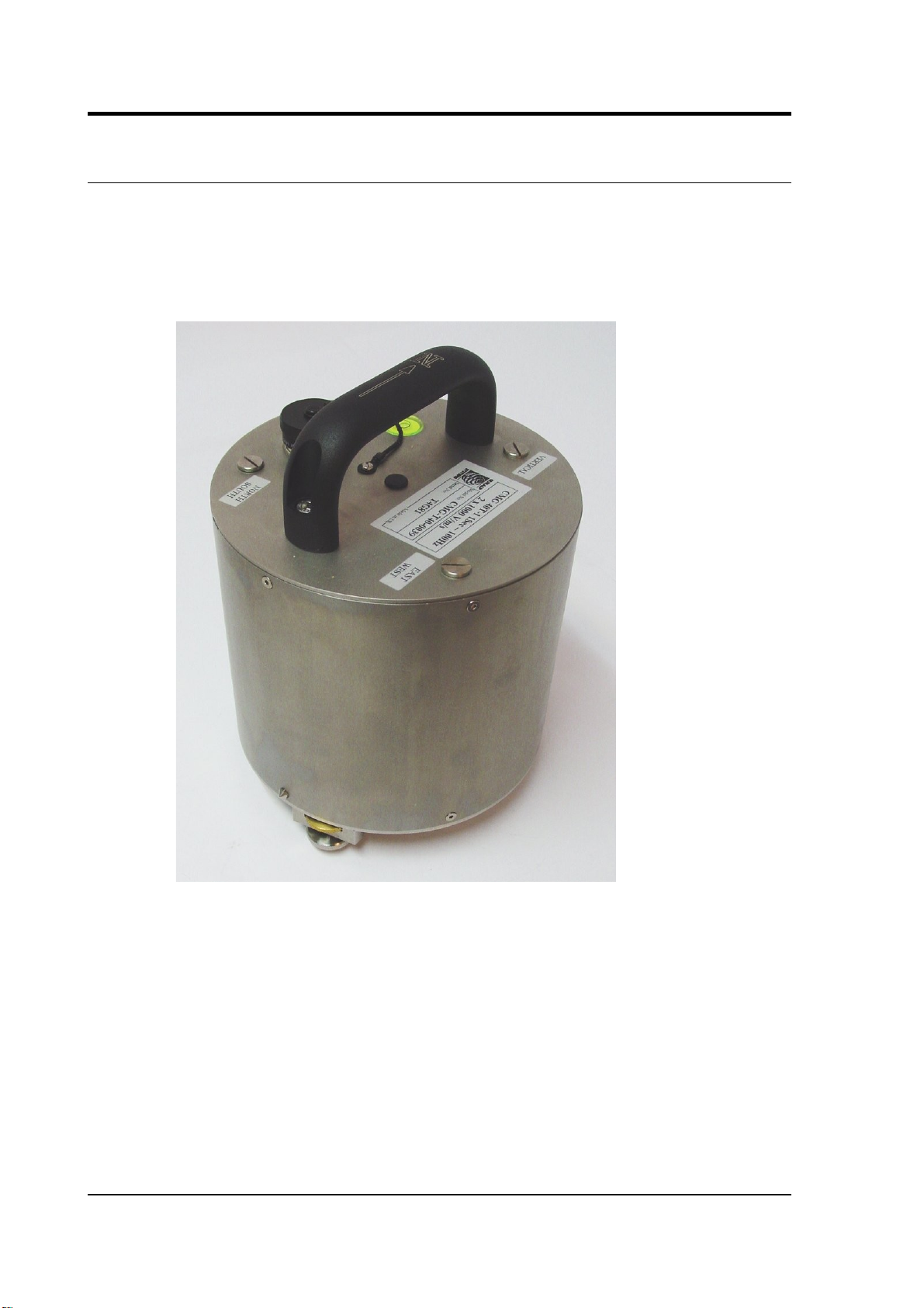
The CMG-40T is an ultra-lightweight seismometer consisting of three sensors
in a sealed case, which can measure the north/south, east/west and vertical
components of ground motion simultaneously.
The 40T has a rugged, waterproof stainless steel design for ease of installation.
The lightweight sensor elements are designed so that no mechanical clamping is
required. Because of this, the 40T is ready to record ground movements as soon
as you provide it with power. In addition, the sensor does not have to be
levelled or centred as long as the base is within 3 ° of horizontal. For the best
results, however, you should install where possible on a hard, near-horizontal
surface well coupled to the bedrock.
Each seismometer is delivered with a detailed calibration sheet showing its
serial number, measured frequency response in both the long period and the
short period sections of the seismic spectrum, sensor DC calibration levels, and
the transfer function in poles/zeros notation.
4 Issue A
Page 5

Operator's guide
1.1 Response options
The 40T can be supplied with a response which is flat to velocity from 50 Hz to
any of 0.1 Hz (10 s), 0.050 Hz (20 s) or 0.033 Hz (30 s).
If you do not require high-frequency data, a low-pass filter may be installed at a
frequency (below 50 Hz) that you specify.
Standard 40T instruments output signals representing ground velocity on three
pairs of balanced differential lines. An option is available which provides a
second, parallel set of outputs at higher gain. The high-gain outputs have a
sensitivity nominally 10 times higher than the standard (low-gain) outputs.
January 2006 5
Page 6

CMG-40T
2 First encounters
2.1 Handling notes
Although the 40T has a rugged design, it is still a sensitive instrument, and can
be damaged if mishandled. If you are at all unsure about the handling or
installation of the device, you should contact Güralp Systems for assistance.
• Avoid bumping or jolting the sensor when handling or unpacking.
• Do not kink or walk on the data cable (especially on rough surfaces such
as gravel), nor allow it to bear the weight of the sensor.
• Do not connect the instrument to power sources except where instructed.
• Do not ground any of the signal lines from the sensor.
All parts of the 40T are waterproof.
2.2 Connections
The instrument has an integrated cable ending in a 26-pin mil-spec socket
which carries both power and output signals. This is suitable for connecting
directly to a Güralp digitizer.
The breakout box, if ordered, provides individual signal and power connectors,
or you can make up your own cable if you prefer.
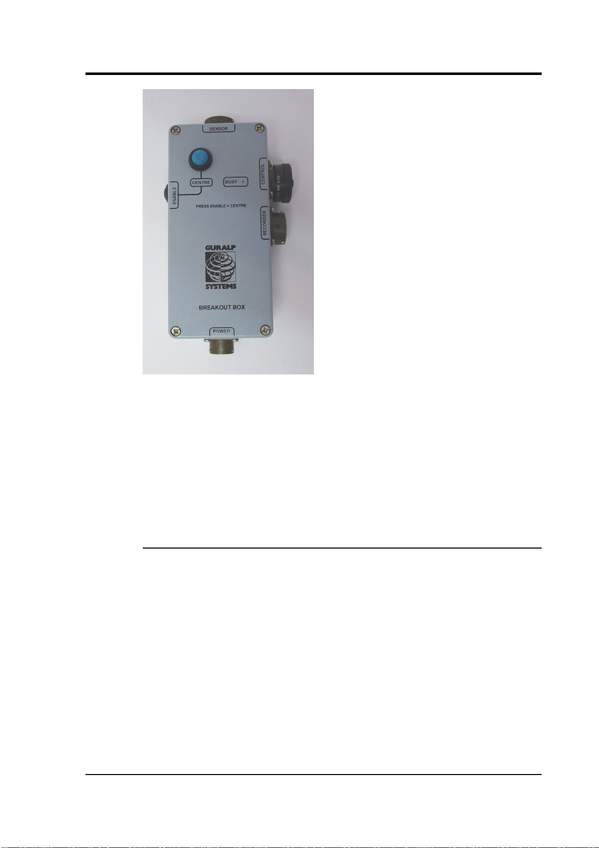
The breakout box
If you are using a Güralp breakout box, it should be attached to the sensor
through its SENSOR connector. Connectors are also provided at the CONTROL
and RECORDER outputs, for attaching to a handheld control unit or a Güralp
digitizer. If you have ordered a 40T with optional high gain outputs, you will
need to make up a suitable cable to expose these outputs.
6 Issue A
Page 7
Operator's guide
The breakout box also provides a standard Güralp power connector on a 10-pin
mil-spec plug. The 40T draws a nominal current of 48 mA from a 12 V supply
when in use; thus, using a 12 V, 25 Ah sealed heavy-duty lead-acid battery, you
should expect the instrument to operate for around a week without recharging.
The CENTRE button switches the instrument into ACC/VEL mode whilst it is
pressed. This mode allows you to monitor the mass positions whilst you adjust
the offsets manually. If you prefer, you can use the equivalent switch on a
Handheld Control Unit (see below.)
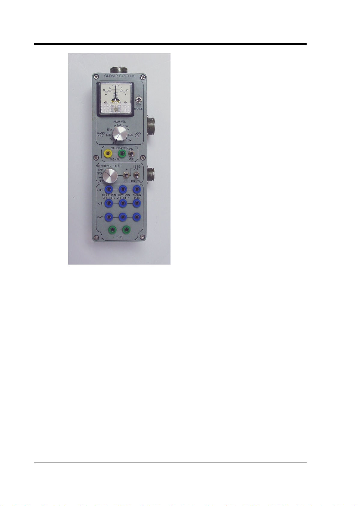
The handheld control unit
This portable control unit provides easy access to the seismometer's control
commands, as well as displaying the output velocity and mass position (i.e.
acceleration) on an analogue meter.
January 2006 7
Page 8
CMG-40T
Signal meter
The upper section of the HCU contains a simple voltmeter for monitoring
various signals from the instrument.
• To monitor the low-gain outputs, switch the dial to V, N/S or E/W LOW
VEL according to the component you want to monitor.
• To monitor the high-gain outputs (on a 40T with that option), switch the
dial to V, N/S or E/W HIGH VEL.
• To monitor the mass position outputs, switch the dial to V, N/S or E/W
MASS POS. Whilst you are adjusting mass position offsets, you should
also switch the instrument out of broadband mode by switching the
rightmost CENTRING SELECT switch to 1 SEC VEL, or by holding
down the CENTRE button on a breakout box.
• You can set the range of the meter with the RANGE switch. When
switched to 10 V, the meter ranges from –10 to + 10 V (as marked.)
When switched to 1 V, the range is –1 to +1 V.
8 Issue A
Page 9

Operator's guide
Calibration
You can calibrate a 40T sensor through the HCU by connecting a signal
generator across the yellow and green CALIBRATION SIGNAL inputs and
setting the adjacent switch to ON. The sensor's response can now be monitored
or recorded, and calibration calculations carried out. See Chapter 4, “Calibrating
the 40T” for full details.
Control commands
If you have ordered a 40T with the remote null facility, you can zero its mass
position offsets from the HCU.
1. Select the component you want to centre from the CENTRING SELECT
dial.
2. Switch the signal meter dial to one of the MASS POS settings.
3. Switch the rightmost switch to 1 SEC VEL to enable the centring lines.
4. Press the +/– switch towards – to centre a mass from a positive value, or
towards + to centre it from a negative value.
Banana plugs
The remainder of the HCU provides useful connections for each of the signal
lines from the instrument, for attaching to your own equipment as necessary.
2.3 Zeroing the instrument
Before installing the 40T, you should check that the mass positions are not
significantly offset from zero. The mass position offsets can be affected by any
tilt to the instrument, as well as handling during transportation. The normal
range of the mass positions is ±10 V; you should zero the instrument if any
mass reads more than around ±3.5 V when the sensor is stationary.
The velocity outputs of the 40T are set at the factory to a nominal value below
±3 mV. Once the instrument is installed and has reached thermal equilibrium
with its environment, these outputs should be similar to the factory-set value.
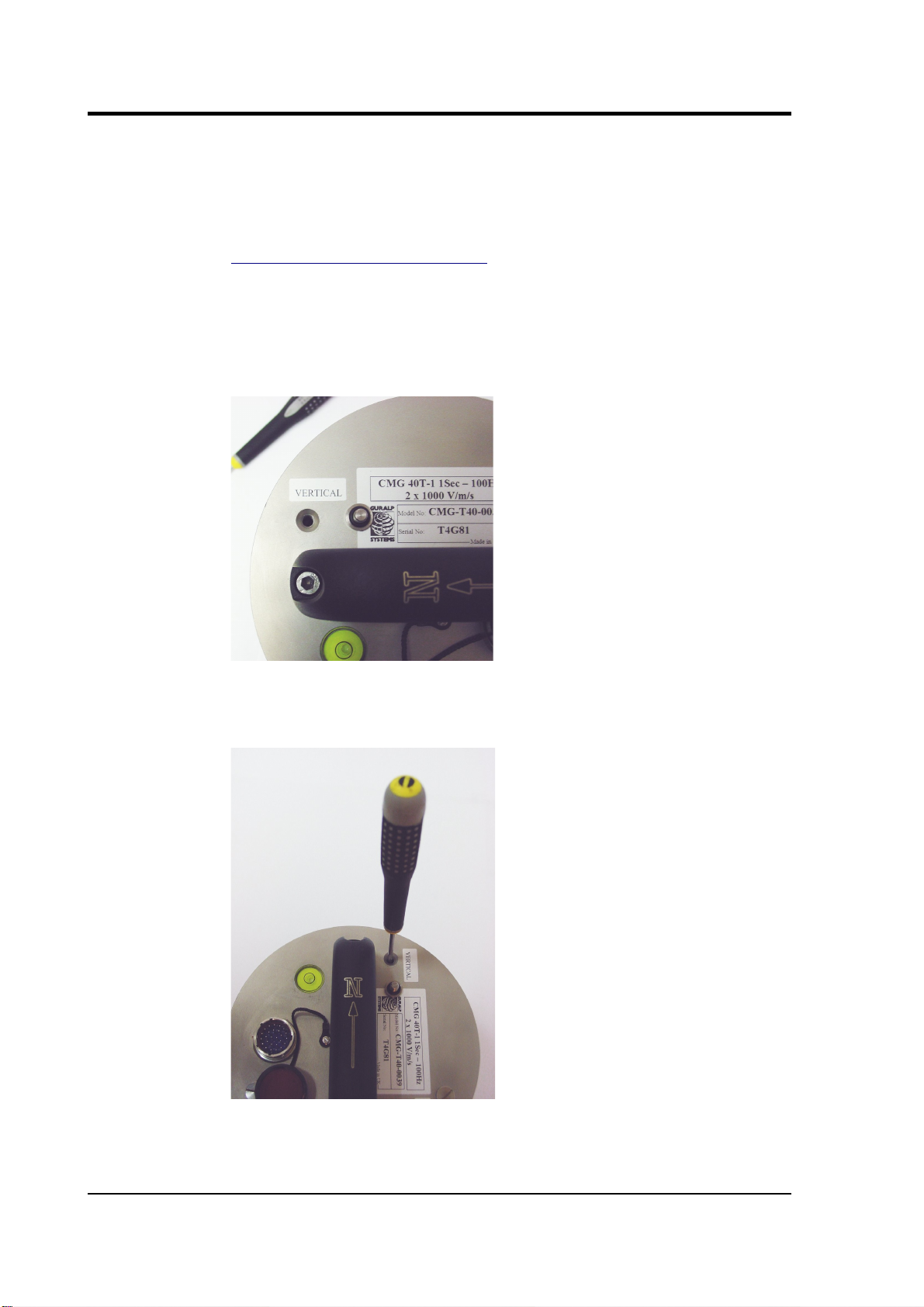
Adjusting the mass position offsets manually
The 40T has three potentiometers (“pots”) accessible within its casing, which
should be used to remove any DC offsets electronically:
1. Bring the instrument into 1 second response mode by applying a voltage
across the Acc/Vel and Signal Ground pins of the input. If you are using
January 2006 9
Page 10
CMG-40T
a DM24, you can do this by sending a CENTRE command. If you are
using a Handheld Control Unit, you should select 1 SEC VEL from the
Velocity Select switch.
2. Measure the vertical mass position output with a 10 V voltmeter (see
Appendix A, “Connector pinouts”) or by selecting MASS POS, V from a
Handheld Control Unit's Display Select knob. If using a HCU, also
check that the Centring Select knob is set to OFF.
3. If the vertical component needs adjusting, remove the cap on the lid
which protects the Verticalpot with a flat-bladed screwdriver (provided).
4. Insert the screwdriver through the opening, and engage the pot. An LED
flashlight may be useful for locating the head.
5. Turn the pot either way until the offset readout is as close to 0 V as
possible.
10 Issue A
Page 11

Operator's guide
6. Repeat steps 2 – 5 for the north/south and east/west components.
Adjusting the mass position offsets with a Handheld Control Unit
Some 40T units are equipped with a remote mass centring option, which allows
you to adjust the internal potentiometers by applying voltages across control
lines to the sensor:
1. Bring the instrument into 1 second response mode by selecting 1 SEC
VEL from the Velocity Select switch.
2. Measure the vertical mass position output by selecting MASS POS, V
from the Handheld Control Unit's Display Select knob.
3. Set the Centring Select knob to V.
4. Press the spring-loaded switch towards + or – to bring the mass position
offset from negative or positive values towards zero.
5. Repeat steps 3 and 4 for the N/S and E/W components.
6. Return the instrument to broadband mode by selecting BB VEL from the
Velocity Select switch.
Zeroing a 40TD digital instrument
The offset potentiometers in a 40TD are in the same place as on the 40T. To
access them, you will need to remove the digitizer module, which lies on top of
the sensor itself. You can monitor the mass position outputs of the sensor using
a Handheld Control Unit and an adapter cable, available from Güralp Systems.
To change the offsets of a 40TD without digital centring:
1. Check the bubble level on the lid of the instrument, to ensure it is not
tilted. If necessary, re-level the instrument by adjusting its feet.
2. Unscrew the vent cap on the lid to allow the air pressure to equalise.
January 2006 11
Page 12

CMG-40T
3. Using an Allen key, remove the screws holding the digitizer module
onto the sensor.
4. Place a flat-head screwdriver in the notches provided, and twist to lever
off the digitizer module.
5. Carefully lift off the digitizer module, and unplug the ribbon cable from
the sensor electronics.
12 Issue A
Page 13

Operator's guide
6. Attach a Handheld Control Unit and adapter cable to the ribbon
connector, and power up the sensor through the control unit.
7. Set the CENTRING SELECT switch on the Handheld Control Unit to 1
SEC VEL, and the monitoring dial to V MASS POS.
8. There are three holes in the topmost electronics board, which provide
access to the offset potentiometers. Insert a screwdriver through the
appropriate hole, and engage the potentiometer for the vertical
component.
9. Adjust the potentiometer until the mass position output reads close to
zero.
10.Repeat steps 4 – 6 for the north/south and east/west components.
Alternatively, you can adjust the mass postions and monitor the output digitally.
1. Remove the vent cap, and use an Allen key to remove the screws
holding the digitizer module onto the sensor as above.
2. Carefully lift off the digitizer module, and support it nearby, leaving the
ribbon cable connected. Extension cables can be obtained from Güralp
January 2006 13
Page 14

CMG-40T
Systems; otherwise, you can use the casing of the sensor itself as a
support.
The steel sensor housing can be removed with an Allen key.
3. Whilst monitoring the mass position outputs (channels M8, M9 and MA),
adjust the potentiometers as above.
2.4 Installation notes
For the best possible results, a seismometer should be installed on a seismic pier
in a specially-built vault, where conditions are near perfect. Here, wave-trains
arriving at the instrument reflect very well the internal motion of subsurface
rock formations. However, this is not always feasible. For example,
• instruments may need to be deployed rapidly, perhaps to monitor the
activity of a volcano showing signs of rejuvenation, or to study the
aftershocks of a major earthquake;
• installations may be required in remote locations, or otherwise in
circumstances where it is unfeasible to build a vault.
In these situations, the seismometer and its emplacement need to be considered
as a mechanical system, which will have its own vibrational modes and
resonances. These frequencies should be raised as high as possible so that they
do not interfere with true ground motion: ideally, beyond the range of the
instrument. This is done by
• standing the sensor on bedrock where possible, or at least deep in well-
compacted subsoil;
• clearing the floor of the hole of all loose material; and
• using as little extra mass as possible in preparing the chamber.
14 Issue A
Page 15

Operator's guide
In temporary installations, environmental factors are also important. The sensor
needs to be well protected against
• fluctuations in temperature,
• turbulent air flow around walls or trees, or around sharp corners or edges
in the immediate vicinity of the sensor;
• vibration caused by heavy machinery (even at a distance), or by
overhead power lines.
This can be done by selecting a suitable site, and placing the instrument in a
protective enclosure. An open-sided box of 5 cm expanded polystyrene slabs,
placed over the instrument and taped down to exclude draughts, makes an
excellent thermal shield.
After installation, the instrument case and mounting surface will slowly return
to the local temperature, and settle in their positions. This will take around four
hours from the time installation is completed.
January 2006 15
Page 16

CMG-40T
3 Installing the 40T
3.1 Installing in vaults
The 40T is a sensitive instrument designed to measure extremely small
movements of the ground. These movements are the sum of all the vibrations
arriving at the instrument: as well as distant earthquakes and nearby tremors, the
ground responds to surf on nearby beaches, quarry blasts, heavy machinery,
traffic, and even people moving around the building. Temperature changes and
air currents in the same room as the sensor can also affect its output.
Choosing a location
When studying natural earth movements, any other effects introduce unwanted
noise into the system. It is therefore important to choose an appropriate site for
the instrument, ideally in an underground vault with the sensor installed on a
concrete pier that is in direct contact with the bedrock.
This setup has a number of advantages:
• It is installed below ground. Most man-made noise tends to travel along
the surface, and natural microseisms (tiny natural flexings of the Earth's
crust) also occur near the surface.
• Good contact with bedrock means that the signals accurately reflect
earth motions; seismic waves do not have to travel through layers of soft
soil and sediment.
• If the vault is inside a larger structure, its foundations are separated from
16 Issue A
Page 17

Operator's guide
the pier, so that nearby vibrations are not transmitted to the sensor.
A high-quality seismic vault can be incorporated into the construction plans of a
new building at relatively low cost. However, if you are not in a position to
build a dedicated vault, you can still reduce noise to a satisfactory level by
• installing below ground, in the basement or sub-basement of an existing
building;
• placing the sensor directly on a cement floor to improve contact; and
• locating the sensor in a quiet corner away from people and machinery
(e.g. air conditioning and heating systems, elevators, etc.)
Installation on higher floors is not recommended, especially for horizontal
sensors, since any “give” in the floor near the sensor will cause it to tilt slightly
and register a signal.
Temperature stability
The 40T can operate over a wide temperature range (–10 °C to +75 °C).
However, the sensor mass is sensitive to fluctuations in local temperature. This
affects the response of the instrument at long periods. Sunlight and other bright
lights can also cause small mechanical stresses that will be detected by the
sensor. You can minimise these effects by
• installing in a basement, where the temperature is normally more stable
than above ground;
• locating the sensor in a dark, protected corner, and
• enclosing it in an insulated box (expanded polystyrene works very well).
This also helps protect the sensor from air currents.
January 2006 17
Page 18

CMG-40T
Other considerations
• The sensor and cables should be situated well away from other electical
cables and appliances. Stray radiation from these sources may interfere
with the sensor's electronics.
• The sensor should be placed on a smooth, level surface free from cracks.
Small cracks tend to open and close slightly with changes in humidity
and temperature, causing the surface to move slightly.
• All three of the sensor's metal feet must make good contact with the
floor.
• The signal cable from the sensor should rest loosely on the ground
nearby, so that vibrations are not transmitted along it.
• If your recording or digitizing equipment has front-panel indicators or
connectors, make sure it can be reached without disturbing the sensor.
• The GPS unit needs to be in a location where it can see as many
satellites as possible. A location with a good view of the sky, preferably
down to the horizon, is recommended. If you are in the Northern
Hemisphere, make sure as much of the southern sky as possible is
visible. Conversely, in the Southern Hemisphere, make sure the GPS can
see a large area of sky to the north.
The GPS unit is supplied with a 15 m cable to the digitizer.
18 Issue A
Page 19
Operator's guide
3.2 Installing in pits
For outdoor installations, high-quality results can be obtained by constructing a
seismic pit.
Depending on the time and resources available, this type of installation can suit
all kinds of deployment, from rapid temporary installations to medium-term
telemetered stations.
Ideally, the sensor should rest directly on the bedrock for maximum coupling to
surface movements. However, if bedrock cannot be reached, good results can be
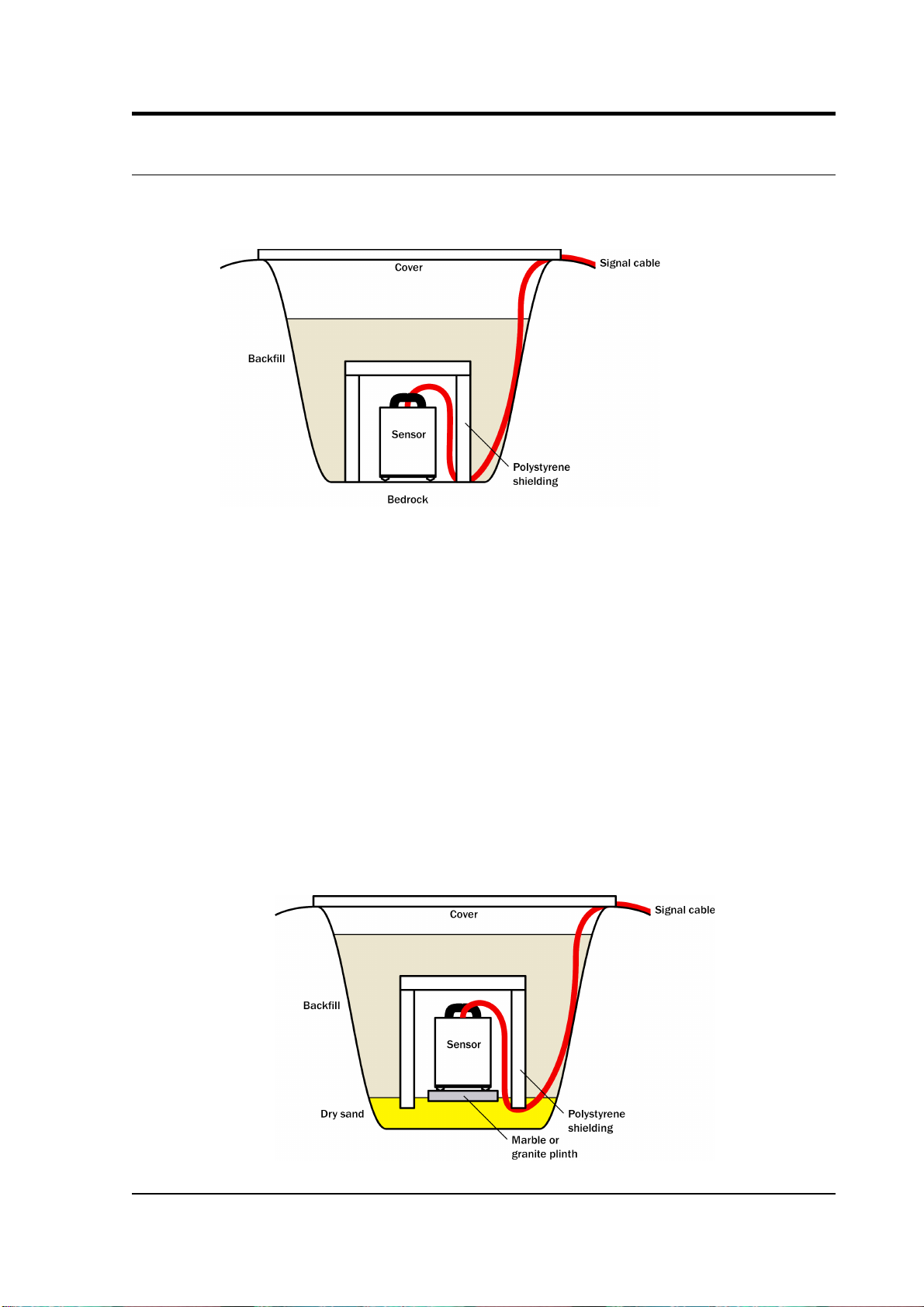
obtained by placing the sensor on a granite pier on a bed of dry sand.
1. Prepare a hole of 60 – 90 cm depth to compacted subsoil, or down to the
bedrock if possible.
2. On granite or other hard bedrock, use an angle grinder to plane off the
bedrock at the pit bottom so that it is flat and level. Stand the instrument
directly on the bedrock, and go to step 7.
3. On soft bedrock or subsoil, you should install a pier as depicted below.
January 2006 19
Page 20

CMG-40T
4. Pour a layer of loose, fine sand into the pit to cover the base. The type of
sand used for children's sand-pits is ideal, since the grains are clean, dry
and within a small size range. On top of the sand, place a smooth, flat
granite plinth around 20 cm across, and shift it to compact the sand and
provide a near-level surface.
Placing a granite plinth on a sand layer increases the contact between the
ground and the plinth, and improves the performance of the instrument.
There is also no need to mix concrete or to wait for it to set, as in step 4.
5. Alternatively, if time allows and granite is not available, prepare a
concrete mix with sand and fine grit, and pour it into the hole. Agitate
(“puddle”) it whilst still liquid, to allow it to flow out and form a level
surface, then leave to set. Follow on from step 7.
Puddled concrete produces a fine-textured, level floor for emplacing the
seismometer. However, once set hard, the concrete does not have the
best possible coupling to the subsoil or bedrock, which has some leeway
to shift or settle beneath it.
6. Alternatively, for the most rapid installation, place loose soil over the
bottom of the pit, and compact it with a flat stone. Place the seismometer
on top of this stone. This method emulates that in step 3, but can be
performed on-site with no additional equipment.
7. Set up the instrument as described in Section 3.1, “Installing in vaults”
(steps 4 to 9).
8. The instrument must now be shielded from air currents and temperature
fluctuations. This is best done by covering it with a thermal shield.
An open-sided box of 5 cm expanded polystyrene slabs is recommended.
If using a seismic plinth on sand (from steps 3–4 or 5), ensure that the
box is firmly placed in the sand, without touching the plinth at any point.
20 Issue A
Page 21

Operator's guide
In other installations, tape the box down to the surface to exclude
draughts.
9. Alternatively, if a box is not available, cover the instrument with fine
sand up to the top.
The sand insulates the instrument and protects it from thermal
fluctuations, as well as minimizing unwanted vibration.
10.Ensure that the sensor cable is loose and that it exits the seismometer
enclosure at the base of the instrument. This will prevent vibrations from
being inadvertently transmitted along the cable.
11.Cover the pit with a wooden lid, and back-fill with fresh turf.
Other installation methods
The recommended installation methods have been extensively tested in a wide
range of situations. However, past practice in seismometer installation has
varied widely.
Some installations introduce a layer of ceramic tiles between a rock or concrete
plinth and the seismometer (left):
However, noise tests show that this method of installation is significantly
inferior to the same concrete plinth with the tiles removed (right). Horizontal
sensors show shifting due to moisture trapped between the concrete and tiling,
whilst the vertical sensors show pings as the tile settles.
Other installations have been attempted with the instrument encased in plaster
of Paris, or some other hard-setting compound (left):
January 2006 21
Page 22

CMG-40T
Again, this method produces inferior bonding to the instrument, and moisture
becomes trapped between the hard surfaces. We recommend the use of fine dry
sand (right) contained in a box if necessary, which can also insulate the
instrument against convection currents and temperature changes. Sand has the
further advantage of being very easy to install, requiring no preparation.
Finally, many pit installations have a large space around the seismometer,
covered with a wooden roof. Large air-filled cavities are susceptible to currents
which produce lower-frequency vibrations, and sharp edges and corners can
give rise to turbulence. We recommend that a wooden box is placed around the
sensor to protect it from these currents. Once in the box, the emplacement may
be backfilled with fresh turf to insulate it from vibrations at the surface, or
simply roofed as before.
By following these guidelines, you will ensure that your seismic installation is
ready to produce the highest quality data.
22 Issue A
Page 23

Operator's guide
4 Calibrating the 40T
4.1 The calibration pack
All Güralp sensors are fully calibrated before they leave the factory. Both
absolute and relative calibration calculations are carried out. The results are
given in the calibration pack supplied with each instrument:
Works Order : The Güralp factory order number including the instrument, used
internally to file details of the sensor's manufacture.
Serial Number : The serial number of the instrument
Date : The date the instrument was tested at the factory.
Tested By : The name of the testing engineer.
There follows a table showing important calibration information for each
component of the instrument, VERTICAL, NORTH/SOUTH, and EAST/WEST.
Each row details:
Velocity Output (Differential) : The sensitivity of each component to velocity at
1 Hz, in volts per m/s. Because the 40T uses balanced differential outputs, the
signal strength as measured between the +ve and –ve lines will be twice the true
sensitivity of the instrument. To remind you of this, the sensitivities are given as
2 × (single-ended sensitivity) in each case.
Mass Position Output : The sensitivity of the mass position outputs to
acceleration, in volts per m/s². These outputs are single-ended and referenced to
signal ground.
Feedback Coil Constant : A constant describing the characteristics of the
feedback system. You will need this constant, given in amperes per m/s², if you
want to perform your own calibration calculations (see below.)
Power Consumption : The average power consumption of the sensor during
testing, given in amperes and assuming a 12 V supply.
Calibration Resistor : The value of the resistor in the calibration circuit. You
will need this value if you want to perform your own calibration calculations
(see below.)
January 2006 23
Page 24

CMG-40T
Poles and zeroes
Most users of seismometers find it convenient to consider the sensor as a “black
box”, which produces an output signal V from a measured input x. So long as
the relationship between V and x is known, the details of the internal mechanics
and electronics can be disregarded. This relationship, given in terms of the
Laplace variable s, takes the form
( V / x ) (s) = G × A × H (s)
In this equation
• G is the acceleration output sensitivity (gain constant) of the instrument.
This relates the actual output to the desired input over the flat portion of
the frequency response.
• A is a constant which is evaluated so that A × H (s) is dimensionless and
has a value of 1 over the flat portion of the frequency response. In
practice, it is possible to design a system transfer function with a very
wide-range flat frequency response.
The normalising constant A is calculated at a normalising frequency
value fm = 1 Hz, with s = j fm, where j = –1. √
• H (s) is the transfer function of the sensor, which can be expressed in
factored form:
In this equation zn are the roots of the numerator polynomial, giving the
zeros of the transfer function, and pm are the roots of the denominator
polynomial giving the poles of the transfer function.
In the calibration pack, G is the sensitivity given for each component on the first
page, whilst the roots zn and pm, together with the normalising factor A, are
given in the Poles and Zeros table. The poles and zeros given are measured
directly at Güralp Systems' factory using a spectrum analyser. Transfer
functions for the vertical and horizontal sensors may be provided separately.
24 Issue A
Page 25

Operator's guide
Frequency response curves
The frequency response of each component of the 40T is described in the
normalised amplitude and phase plots provided. The response is measured at
low and high frequencies in two separate experiments. Each plot marks the lowfrequency and high-frequency cutoff values (also known as –3 dB or half-power
points).
If you want to repeat the calibration to obtain more precise values at a frequency
of interest, or to check that a sensor is still functioning correctly, you can inject
calibration signals into the system using a Güralp digitizer or your own signal
generator, and record the instrument's response.
Obtaining copies of the calibration pack
Our servers keep copies of all calibration data that we send out. In the event that
the calibration information becomes separated from the instrument, you can
obtain all the information using our free e-mail service. Simply e-mail
caldoc@guralp.com with the serial number of the instrument in the subject
line, e.g.
From: your@email.net
To: caldoc@guralp.com
Subject: T3A15
The server will reply with the calibration documentation in Word format. The
body of your e-mail will be ignored.
January 2006 25
Page 26

CMG-40T
4.2 Calibration methods
Velocity sensors such as the 40T are not sensitive to constant DC levels, either
as a result of their design or because of an interposed high-pass filter. Instead,
three common calibration techniques are used.
• Injecting a step current allows the system response to be determined in
the time domain. The amplitude and phase response can then be
calculated using a Fourier transform. Because the input signal has
predominantly low-frequency components, this method generally gives
poor results. However, it is simple enough to be performed daily.
• Injecting a sinusoidal current of known amplitude and frequency allows
the system response to be determined at a spot frequency. However,
before the calibration measurement can be made the system must be
allowed to reach a steady state; for low frequencies, this may take a long
time. In addition, several measurements must be made to determine the
response over the full frequency spectrum.
• Injecting white noise into the calibration coil gives the response of the
whole system, which can be measured using a spectrum analyser.
You can perform calibration either using a Güralp DM24 digitizer, which can
generate step and sinusoidal calibration signals, or by feeding your own signals
into the instrument through a handheld control unit.
Before you can calibrate the instrument, its calibration relays need to be
activated by pulling low the CAL ENABLE line on the instrument's connector
for the component you wish to calibrate. Once enabled, a calibration signal
provided across the CAL SIGNAL and SIGNAL GROUND lines will be routed
through the feedback system. You can then measure the signal's equivalent
velocity on the sensor's output lines. Güralp Handheld Control Units provide a
switch for activating the CAL ENABLE line.
4.3 Calibration with Scream!
Güralp digitizers provide calibration signal generators to help you set up your
sensors. Calibration is most easily done through a PC running Güralp's Scream!
software.
Depending on the digitizer type, sine-wave, step and broadband noise signal
generators may be available. In this section, broadband noise calibration will be
used to determine the complete sensor response in one action. Please refer to the
digitizer's manual for information on other calibration methods.
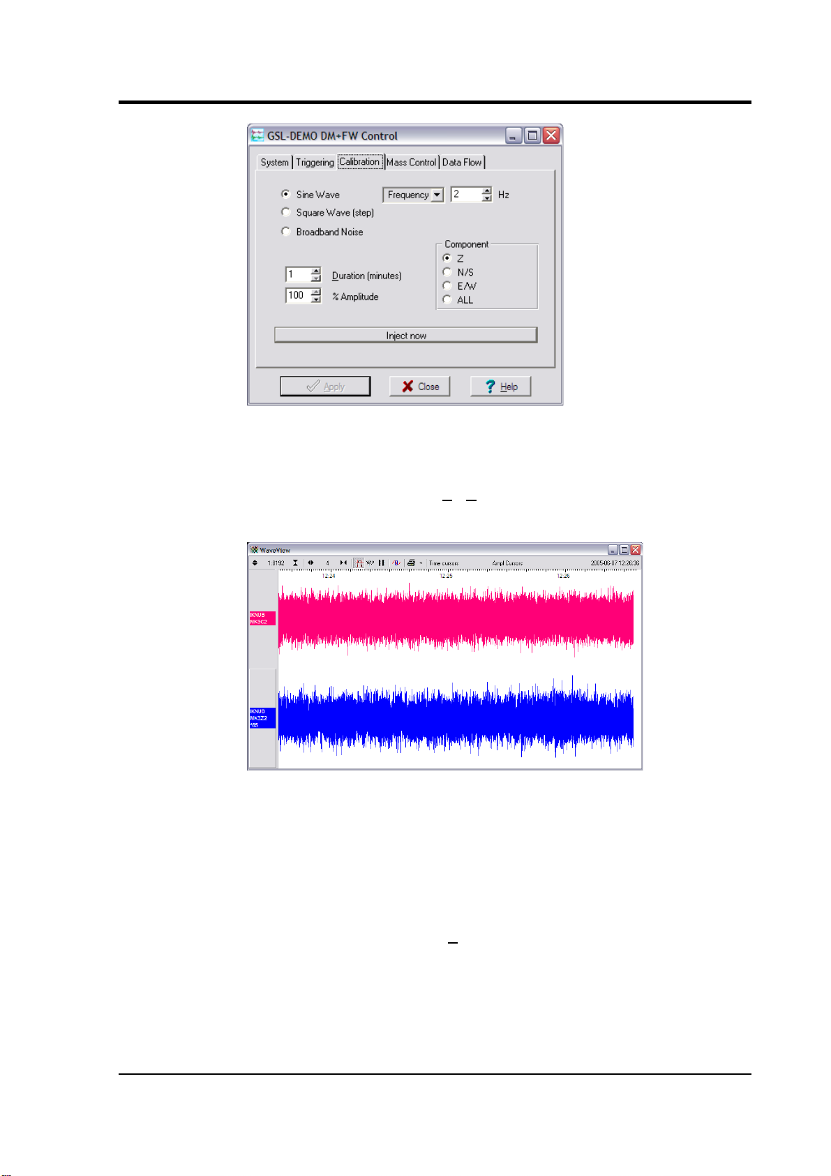
1. In Scream!'s main window, right-click on the digitizer's icon and select
Control.... Open the Calibration pane.
26 Issue A
Page 27
Operator's guide
2. Select the calibration channel corresponding to the instrument, and
choose Broadband Noise. Select the component you wish to calibrate,
together with a suitable duration and amplitude, and click Inject now. A
new data stream, ending Cn (n = 0 – 7) or MB, should appear in
Scream!'s main window containing the returned calibration signal.
3. Open a Waveview window on the calibration signal and the returned
streams by selecting them and double-clicking. The streams should
display the calibration signal combined with the sensors' own
measurements. If you cannot see the calibration signal, zoom into the
Waveview using the scaling icons at the top left of the window or the
cursor keys.
Drag the calibration stream Cn across the Waveview window, so that it
is at the top.
4. If the returning signal is saturated, retry using a calibration signal with
lower amplitude, until the entire curve is visible in the Waveview
window.
January 2006 27
Page 28

CMG-40T
5. If you need to scale one, but not another, of the traces, right-click on the
trace and select Scale.... You can then type in a suitable scale factor for
that trace.
6. Pause the Waveview window by clicking on the icon.
7. Hold down SHIFT and drag across the window to select the calibration
signal and the returning component(s). Release the mouse button,
keeping SHIFT held down. A menu will pop up. Choose Broadband
Noise Calibration.
8. The script will ask you to fill in sensor calibration parameters for each
component you have selected.
Most data can be found on the calibration sheet for your sensor. Under
Instrument response, you should fill in the sensor response code for your
sensor, according to the table below. Instrument Type should be set to
the model number of the sensor.
If the file calvals.txt exists in the same directory as Scream!'s
28 Issue A
Page 29
Operator's guide
executable (scream.exe), Scream! will look there for suitable
calibration values. A sample calvals.txt is supplied with Scream!,
which you can edit to your requirements. Each stream has its own
section in the file, headed by the line [instrument-id]. The
instrument-id is the string which identifies the digitizer in the left-hand
pane, e.g. GURALP-DEMO. It is always 6 characters (the system
identifier) followed by a dash, then 4 characters (the serial number.) For
example:
[instrument-id]
Serial-Nos=T3X99
VPC=3.153,3.147,3.159
G=1010,1007,1002
COILCONST=0.02575,0.01778,0.01774
CALVPC=3.161
CALRES=51000
TYPE=sensor-type
RESPONSE=response-code
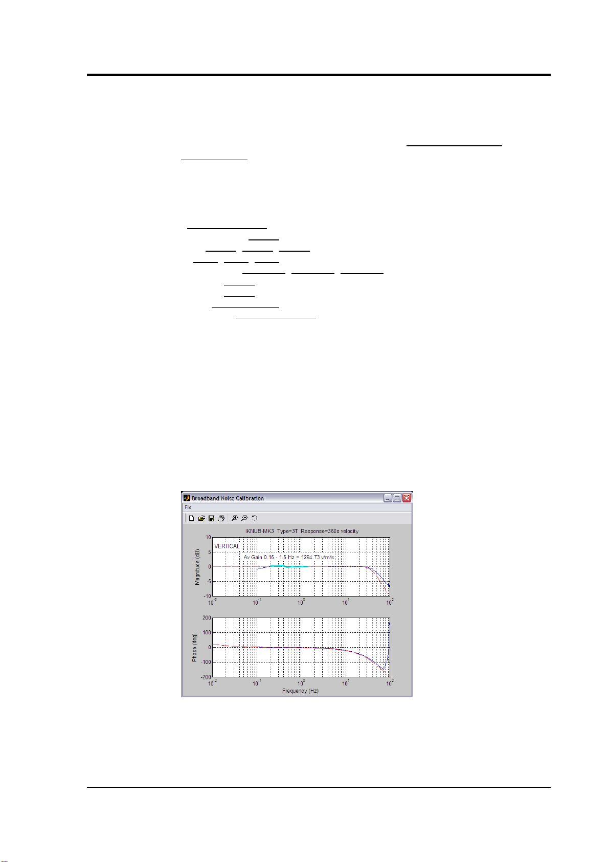
9. Click OK. The script will return with a graph showing the responsivity of
the sensor in terms of amplitude and phase plots for each component (if
appropriate.)
The accuracy of the results depends on the amount of data you have
selected, and its sample rate. To obtain good-quality results at low
frequency, it will save computation time to use data collected at a lower
sample rate; although the same information is present in higher-rate
streams, they also include a large amount of high-frequency data which
may not be relevant to your purposes.
The bbnoisecal script automatically performs appropriate averaging
to reduce the effects of aliasing and cultural noise.
January 2006 29
Page 30

CMG-40T
Sensor response codes
Sensor Sensor type code Units (V/A)
CMG-5T or 5TD, DC – 100 Hz response
CMG-5_100HZ A
CMG-40T-1 or 6T-1, 1 s – 100 Hz response
CMG-40_1HZ_50HZ V
CMG-40_1S_100HZ V
CMG-40T-1 or 6T-1, 2 s – 100 Hz response
CMG-40_2S_100HZ V
CMG-40T-1 or 6T-1, 10 s – 100 Hz response
CMG40_10S_100HZ
V
CMG-40, 20 s – 50 Hz response
CMG-40_20S_50HZ V
CMG-40, 30 s – 50 Hz response
CMG-40_30S_50HZ V
CMG-3T or 3ESP, 30 s – 50 Hz response
CMG-3_30S_50HZ V
CMG-40, 60 s – 50 Hz response
CMG-40_60S_50HZ V
CMG-3T or 3ESP, 60 s – 50 Hz response
CMG-3_60S_50HZ V
CMG-3T or 3ESP, 100 s – 50 Hz response
CMG-3_100S_50HZ V
CMG-3T or 3ESP, 120 s – 50 Hz response
CMG-3_120S_50HZ V
CMG-3T, 360 s – 50 Hz response
CMG-3_360S_50HZ V
CMG-3TB or 3V / 3ESP borehole, 30 s – 50 Hz
response
CMG-3B_30S_50HZ V
CMG-3TB or 3V / 3ESP borehole, 100 s – 50 Hz
response
CMG3B_100S_50HZ
V
CMG-3TB or 3V / 3ESP borehole, 120 s – 50 Hz
response
CMG3B_120S_50HZ
V
4.4 Calibration with a handheld control unit
If you prefer, you can inject your own calibration signals into the system
through a handheld control unit. The unit includes a switch which activates the
calibration relay in the seismometer, and 4 mm banana sockets for an external
signal source. As above, the equivalent input velocity for a sinusoidal
calibration signal is given by
v = V / 2 π f R K
where V is the peak-to-peak voltage of the calibration signal, f is the signal
frequency, R is the magnitude of the calibration resistor and K is the feedback
coil constant. R and K are both given on the calibration sheet supplied with the
40T.
The calibration resistor is placed in series with the transducer. Depending on the
calibration signal source, and the sensitivity of your recording equipment, you
30 Issue A
Page 31

Operator's guide
may need to increase R by adding further resistors to the circuit.
4.5 The coil constant
The feedback coil constant K is measured at the time of manufacture, and
printed on the calibration sheet. Using this value will give good results at the
time of installation. However, it may change over time.
The coil constant can be determined by tilting the instrument and measuring its
response to gravity. To do this, you will need apparatus for measuring tilt angles
accurately.
1. Measure the acceleration due to gravity, g, at your location.
2. Tilt the instrument slightly, and measure its attitude and the gain of the
mass position output for the component you wish to calibrate.
3. Repeat this measurement for several tilt angles.
4. For the vertical sensor, the input acceleration is given by a = g sin φ,
whilst for the horizontal sensor, it is a = g ( 1 – cos φ ).
Calculate the input acceleration for each of the tilt angles used, and plot
a graph of mass position output against input acceleration.
5. The gradient of the line obtained gives the sensitivity of the coil (in
V/m/s2, if g was measured in m/s2 and the mass position in V.)
6. The coil constant K is equal to this sensitivity divided by the value of the
displacement feedback resistor, given on the calibration sheet.
January 2006 31
Page 32

CMG-40T
Appendix A Connector pinouts
Appendix A.1 Output port and breakout box RECORDER connector
Models with a 26-pin mil-spec plug (02E-16-26P) have the following pin
assignments.
Pin Function
A Velocity +ve, vertical channel
B Velocity –ve, vertical channel
C Velocity +ve, N/S channel
D Velocity –ve, N/S channel
E Velocity +ve, E/W channel
F Velocity –ve, E/W channel
G Mass position, vertical channel
J Mass position, N/S channel
L Mass position, E/W channel
M – 12 V DC supply (3-way power option)
N Signal ground
P Calibration signal (all channels)
R Calibration enable (all channels)
U Acc/Vel
V N/S centring motor (remote centring option)
W E/W centring motor (remote centring option)
X Vertical centring motor (remote centring option)
Y Motor return (remote centring option)
b Power ground
c + 12 V DC supply
These outputs are compatible with the CMG-3ESP, so you can use CMG-3ESP
handheld control units and breakout boxes to monitor the low-gain velocity
outputs and calibrate. Note: 40T units with the optional additional high-gain
outputs cannot be used with a CMG-3ESP breakout box. The pinouts for these
32 Issue A
Page 33

Operator's guide
sensors are given in the next section.
Pin R, Calibration enable, is equivalent to the vertical calibration enable line on
a CMG-3ESP, so you can calibrate all channels by setting up Scream! or a
handheld control unit to calibrate the vertical channel.
Pressing ENABLE and CENTRE on a CMG-3ESP handheld control unit
activates pin U and switches the 40T into 1 second mode. You must do this
before you can monitor mass position outputs, e.g. for offset zeroing.
Appendix A.2 Output port and breakout box RECORDER connector (high gain option)
These models have a 26-pin mil-spec plug (02E-16-26P) with the following pin
assignments.
Pin Function
A Velocity +ve, vertical channel
B Velocity –ve, vertical channel
C Velocity +ve, N/S channel
D Velocity –ve, N/S channel
E Velocity +ve, E/W channel
F Velocity –ve, E/W channel
G Mass position, vertical channel
H High gain velocity –ve, E/W channel
J Mass position, N/S channel
K High gain velocity +ve, E/W channel
L Mass position, E/W channel
M – 12 V DC supply (3-way power option)
N Signal ground
P Calibration signal (all channels)
R Calibration enable (all channels)
S High gain velocity –ve, vertical channel
T High gain velocity +ve, vertical channel
U Acc/Vel
V N/S centring motor (remote centring option)
W E/W centring motor (remote centring option)
January 2006 33
Page 34

CMG-40T
X Vertical centring motor (remote centring option)
Y Motor return (remote centring option)
Z High gain velocity –ve, N/S channel
a High gain velocity +ve, N/S channel
b Power ground
c + 12 V DC supply
Appendix A.3 Breakout box power connector
This is a standard 10-pin mil-spec plug (02E-12-10P).
Pin Function
A 0 V
B +12 V DC supply
H –12 V DC supply (3-way power option)
34 Issue A
Page 35

Operator's guide
Appendix B Specifications
Outputs and
response
Sensitivity
2 × 160 V/m/s or 2 × 400
V/m/s
Sensitivity (optional high gain
outputs)
2 × 1600 V/m/s or
2 × 4000 V/m/s
Dynamic range > 145 dB
Flat velocity response
0.033 Hz, 0.05 Hz or
0.1 Hz – 50 Hz
Flat acceleration response
DC – 0.33 Hz, 0.05 Hz or
0.1 Hz
High-frequency roll-off See calibration sheet
Output impedance 47 Ω
Differential output ± 10 V
Physical Lowest spurious resonance 450 Hz
Operating temperature range –10 to +60 °C
Base diameter 168 mm
Sensor height
210 mm (including
handle)
Sensor weight 5.0 kg
Power Voltage requirements
10 – 36 V using internal
12 V DC/DC converter
Current at 12 V DC 48 mA
January 2006 35
 Loading...