

Page 1
Installation
1
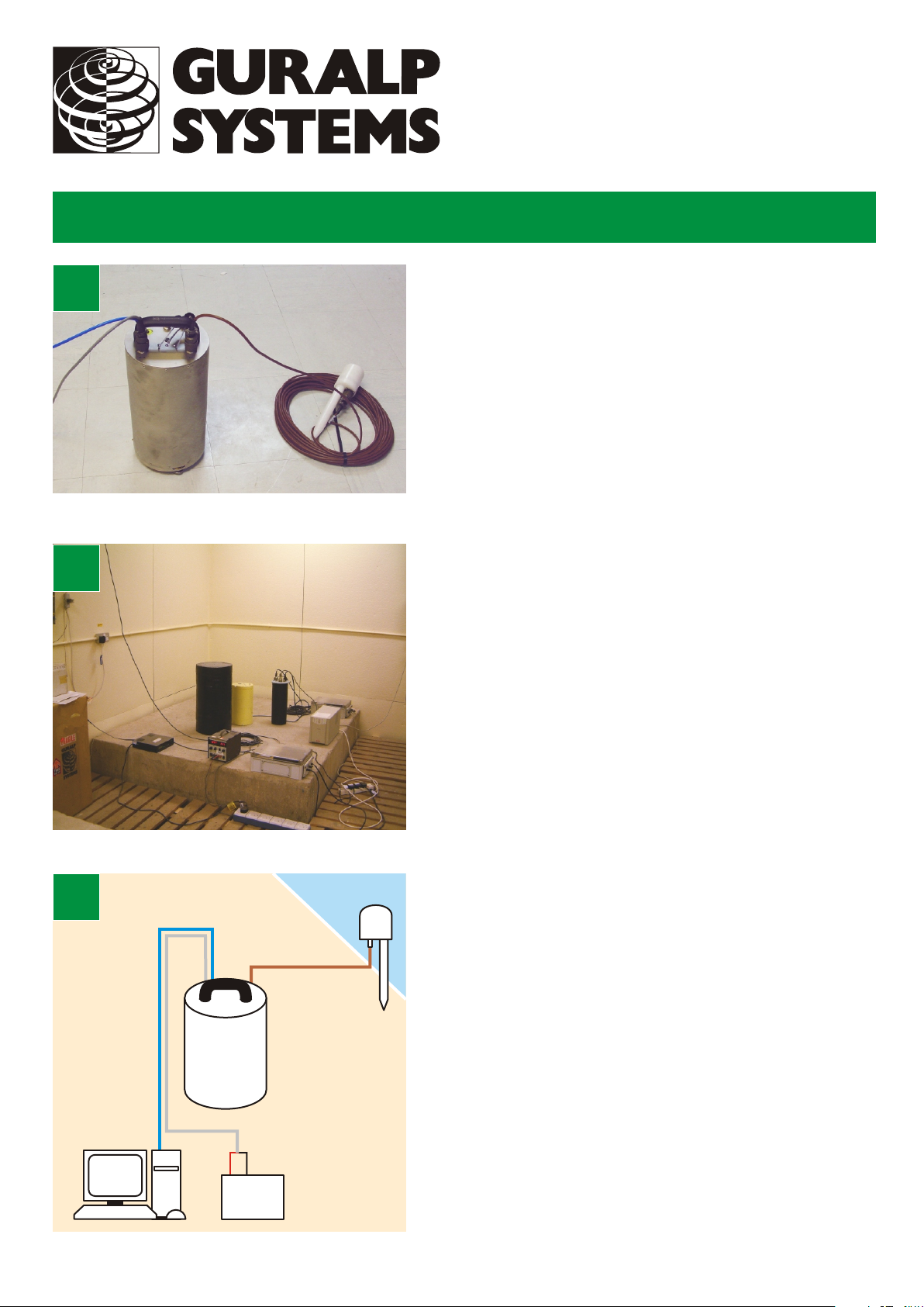
CMG-3TD
Digital sensor
Check that you have all components and cables:
•CMG-3TD digital weak motion seismometer;
•GPS receiver;
•Brown GPS sensor cable;
↔
2
•Blue/grey combined sensor PC and power cables;
•Sensor calibration data booklet.
You will need a Windows or Linux PC with an RS232
serial (COM) port and a 12–24 V DC power supply.
Choose suitable sites to install the sensor and the GPS
receiver. The sensor should be mounted:
•at or, ideally, below ground level;
•in contact with bedrock or, if that is not possible, on
a hard granite or concrete pier;
•in an environment with constant temperature;
•shielded from air currents (e.g. in a polystyrene box);
•away from electrical cables and appliances.
The GPS should be placed:
•within 15 metres of the sensor;
•with a wide view of the sky and a low horizon.
↔
3
RS232
PC
CMG-3TD
+
Power
supply
Connect the various components together:
GPS
–
•Connect the brown cable from the GPS receiver to
the GPS connector on the sensor;
•Connect the 9-pin ‘D’ connector on the blue cable to
your PC’s serial (COM) connector;
•Connect the free, stripped end of the grey cable to
the power supply. Connect the black wire to the
negative (–) terminal and the red wire to the positive
(+) terminal;
•The blue and grey cables are joined together at a 10pin mil-spec socket. Attach this to the DATA
connector on the sensor. Do this step last.
Page 2

Installation
4
5
Loosen the brass locking nut on one of the adjustable
feet. Turn the foot, screwing it in or out to level the
sensor. Check using the spirit level on the sensor lid.
Repeat with the other adjustable feet, until the bubble
in the spirit level lies entirely within the inner circle.
Tighten the brass locking nuts downwards to secure the
feet.
Start the PC and run Güralp Systems’ Scream! software.
If you have not run Scream! before, the Setup window
will open. Otherwise, choose File → Setup... from the
main menu and view the Com Ports tab.
Set the Baud Rate to 38,400 and click OK. Data
streams should start appearing in the main window.
Note that this data will not yet reflect ground
movements, because the masses are still locked.
6
7
Look for the digitizer icon on the left side of the window,
and right-click on it. Choose Control..., and view the
Mass Control tab. Click Unlock, and wait for a few
minutes: The top half of the digitizer icon on the left
should change from grey to green.
If the top half fails to turn green, there is a problem
*
receiving GPS signals.
If the bottom half turns red, the sensor is not level:
*
Move the sensor to a more level surface and try
again.
Select some data streams by double-clicking on them. A
Waveview window will open on the streams. Check that
all three outputs respond to vibrations near the sensor
Do not move the sensor while the masses are
*
unlocked. If you need to transport it, use the Mass
Control tab to lock the masses first.
Please refer to the full manual for detailed usage
instructions, calibration and troubleshooting.
.
MSH-030-0002-B : Page 2 of 2
 Loading...