

Page 1

CMG-3TB
Operator’s guide
Part MAN-BHO-0001
Designed and manufactured by
Güralp Systems Limited
3 Midas House, Calleva Park
Aldermaston RG7 8EA
England
Proprietary Notice: The information in this manual is
proprietary to Güralp Systems Limited and may not be
copied or distributed outside the approved recipient's
organisation without the approval of Güralp Systems
Limited. Güralp Systems Limited shall not be liable for
technical or editorial errors or omissions made herein,
nor for incidental or consequential damages resulting
from the furnishing, performance, or usage of this
material.
Issue C 2006-11-15
Page 2

CMG-3TB
Table of Contents
1 Introduction............................................................................................................... 4
1.1 System configuration.......................................................................................... 5
1.2 Digital borehole installations............................................................................. 6
1.3 The hole lock system.......................................................................................... 7
The single-jaw hole lock...................................................................................... 7
The three-jaw hole lock........................................................................................ 9
2 Assembling the instrument.................................................................................... 11
2.1 Unpacking and packing.................................................................................... 11
2.2 Handling notes.................................................................................................. 11
2.3 Assembling the 3TB.......................................................................................... 12
2.4 Disassembling the instrument.......................................................................... 16
2.5 Control units..................................................................................................... 17
The breakout box................................................................................................ 17
Calibration...................................................................................................... 18
Mass locking and unlocking.......................................................................... 19
Centring.......................................................................................................... 19
The handheld control unit................................................................................. 19
Connections.................................................................................................... 20
Signal meter................................................................................................... 20
Calibration and control.................................................................................. 21
Banana plugs.................................................................................................. 21
The inclinometer monitor unit.......................................................................... 21
2.6 Operating the hole lock.................................................................................... 22
Engaging the hole lock....................................................................................... 23
Disengaging the hole lock.................................................................................. 24
Manual operation............................................................................................... 24
3 Installing the 3TB in a borehole............................................................................. 26
3.1 Installing a sensor with hole lock unit............................................................. 26
3.2 Installing a sensor using sand backfill............................................................. 31
Procedure............................................................................................................ 32
3.3 Assembling the winch...................................................................................... 36
3.4 Earthing a borehole sensor............................................................................... 40
Installations with AC power supplies............................................................... 40
Installations with DC power supplies................................................................ 44
External lightning protection............................................................................. 45
3.5 Levelling and centring...................................................................................... 46
3.6 Downhole orientation....................................................................................... 47
2 Issue C
Page 3

Operator's guide
Installing the Scream! extension....................................................................... 47
Installing the reference instrument................................................................... 47
Measuring the orientation.................................................................................. 48
Applying automatic rotation.............................................................................. 53
4 Calibrating the 3TB................................................................................................. 55
4.1 The calibration pack......................................................................................... 55
Poles and zeroes................................................................................................. 56
Frequency response curves................................................................................ 57
Obtaining copies of the calibration pack........................................................... 57
4.2 Calibration methods......................................................................................... 58
4.3 Calibration with Scream! ................................................................................ 58
Sensor response codes........................................................................................ 62
4.4 Calibration with a handheld control unit........................................................ 62
4.5 The coil constant.............................................................................................. 63
5 Inside the 3TB......................................................................................................... 64
5.1 The sensors....................................................................................................... 64
5.2 The control system........................................................................................... 66
LOCK .................................................................................................................. 66
UNLOCK ............................................................................................................ 67
CENTRE ............................................................................................................. 69
5.3 The feedback system........................................................................................ 70
Hybrid feedback................................................................................................. 71
Conventional-response feedback....................................................................... 72
Comparisons....................................................................................................... 72
6 Connector pinouts................................................................................................... 74
7 Specifications.......................................................................................................... 76
8 Revision history...................................................................................................... 78
November 2006 3
Page 4
CMG-3TB
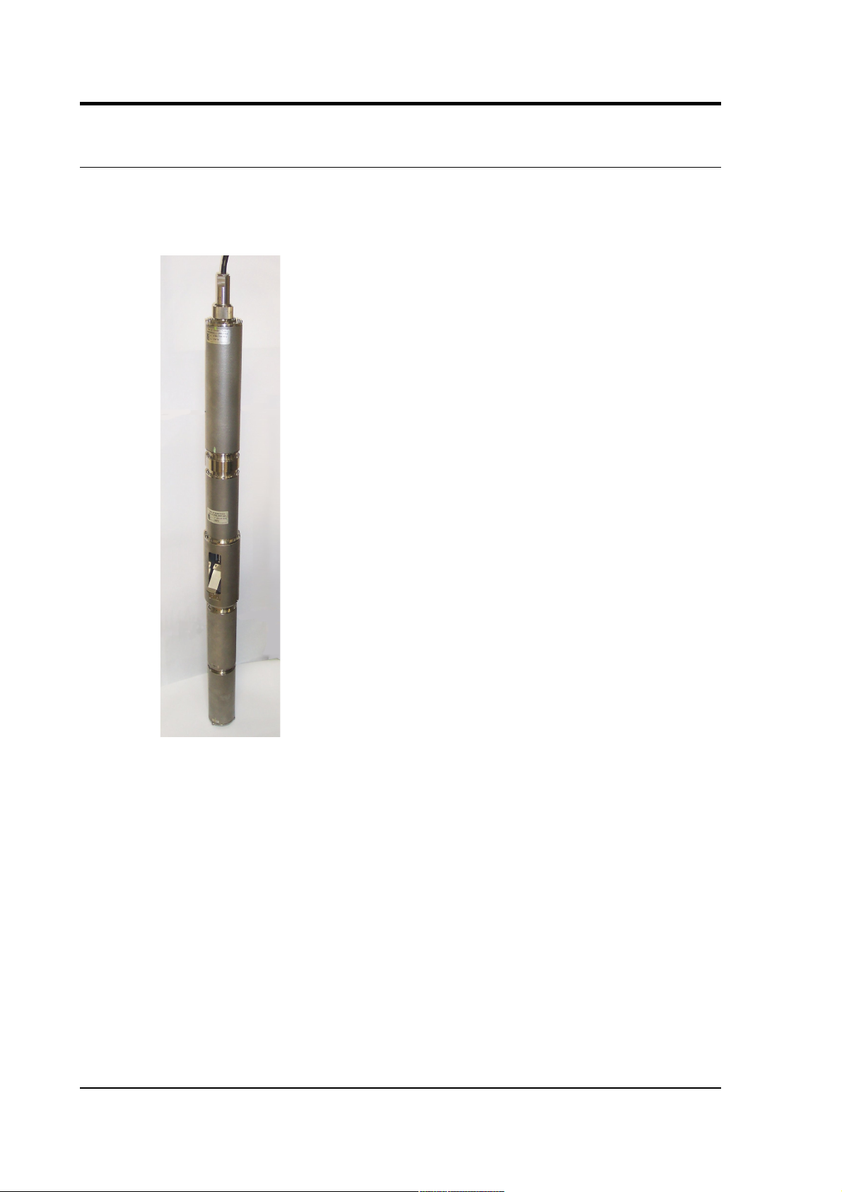
1 Introduction
The CMG-3TB is a three-axis seismometer consisting of three sensors
stacked vertically in a sealed borehole sonde, designed for use in cased
boreholes with diameters between 5” / 89 mm and 9” / 229 mm.
The seismometer system is self-contained except for its 12 – 30 V
power supply, which is provided through the same cable as the
analogue data. Sensor functions such as levelling and mass locking are
carried out through a surface control box.
The 3TB's sensors are sensitive to ground vibrations in the frequency
range 0.0027 – 50 Hz. It outputs analogue voltage representing ground
velocity on balanced differential lines. Each seismometer is delivered
with a detailed calibration sheet showing its serial number, measured
frequency response in both long and short period sections of the
seismic spectrum, sensor DC calibration levels, and the transfer
function in poles/zeros notation.
4 Issue C
Page 5
Operator's guide
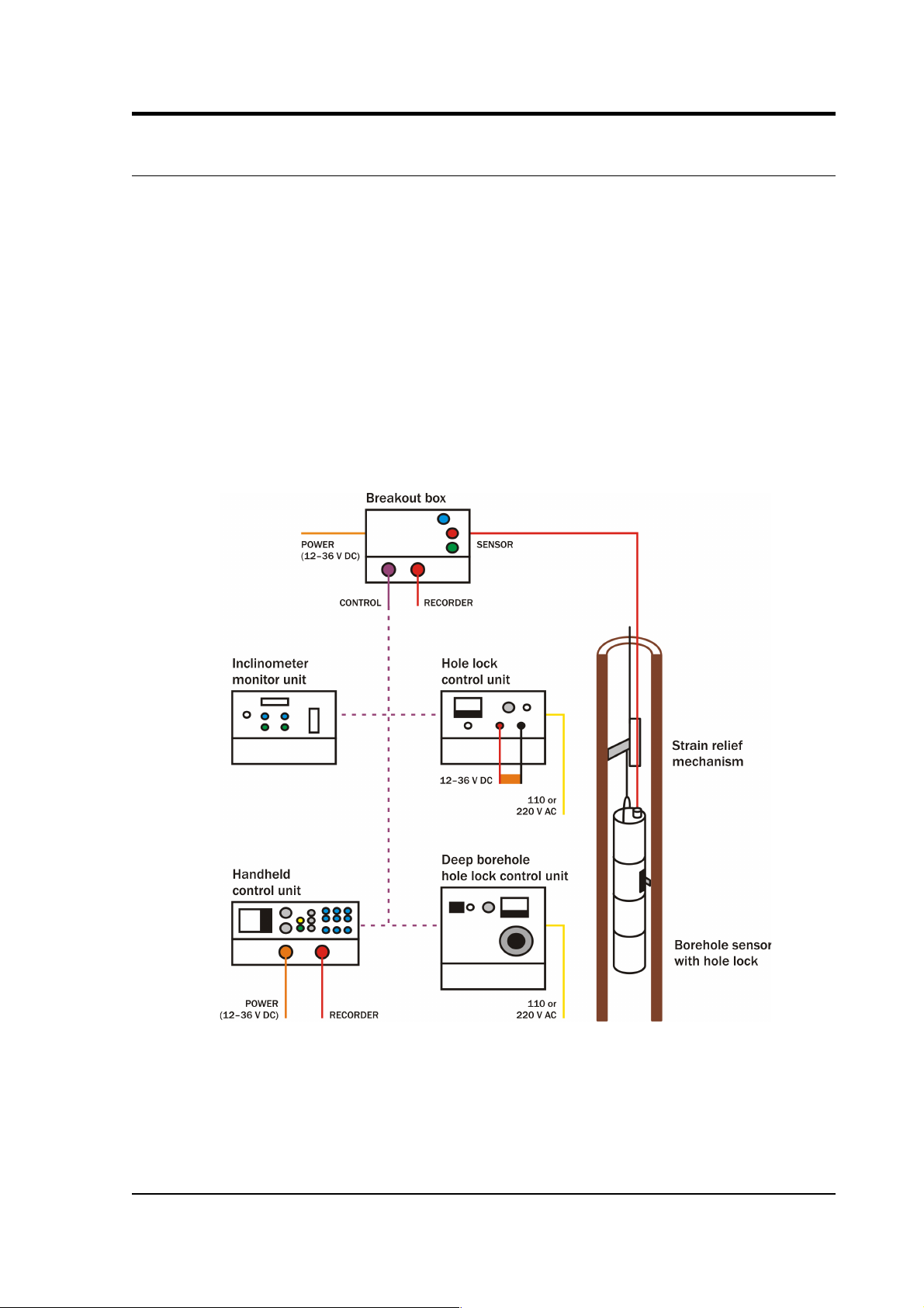
1.1 System configuration
The CMG-3 series of seismic instruments share a number of features:
• a modular sensor sonde, which can be fitted with a single-jaw or
three-jaw holelock mechanism as required,
• a pit head installation including a breakout box, and
• a number of additional, optional control units which may be
connected to the breakout box to perform installation and
maintenance tasks.
For example, a borehole or pit installation of a CMG-3TB or 3ESPB
instrument with single-jaw hole lock has the following layout:
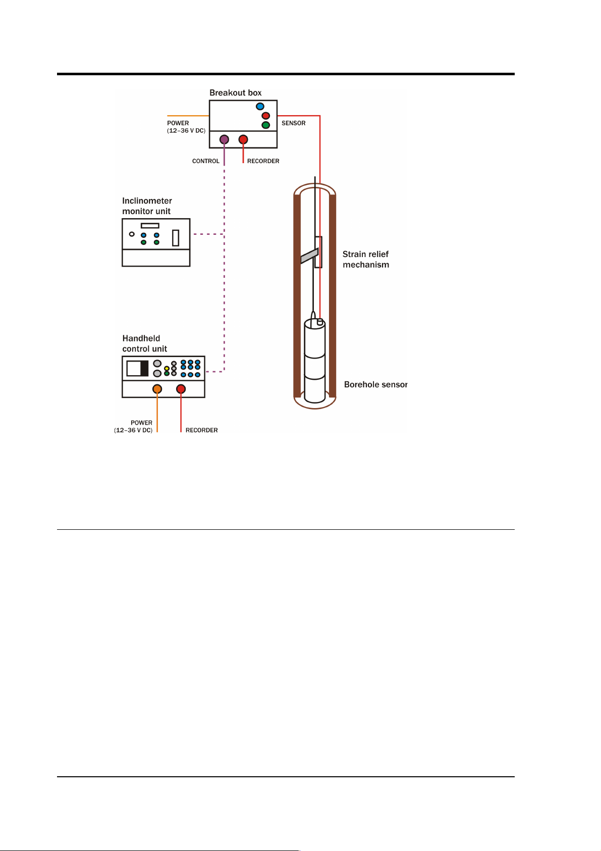
CMG 3-series instruments are also suitable for installing in boreholes
with sand backfill. In this case no hole lock unit is necessary.
November 2006 5
Page 6
CMG-3TB
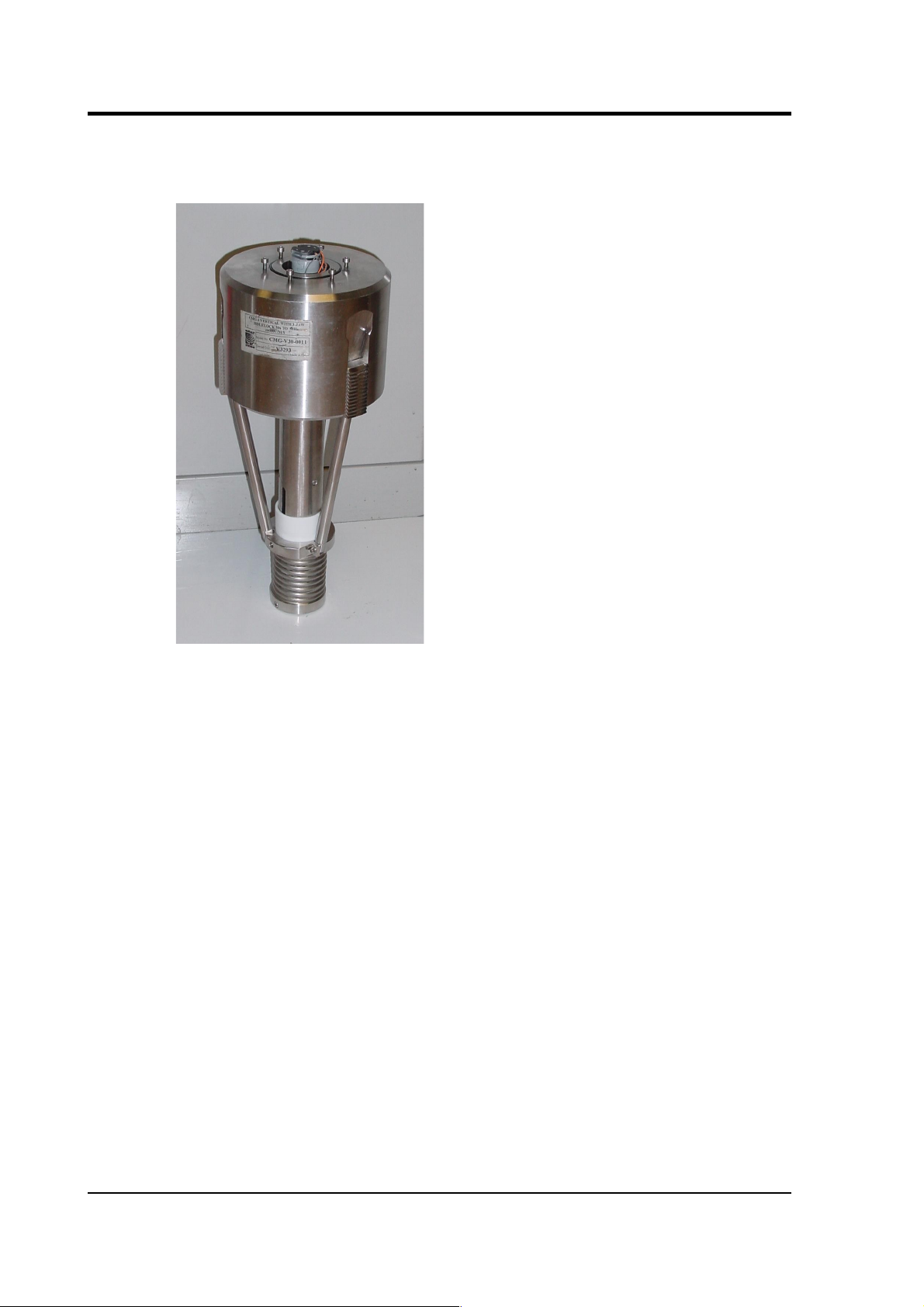
The CMG-3V sensor is identical to the vertical-component module of
the 3TB instrument, allowing you to build mixed arrays of 3V and 3TB
sensors with identical response characteristics.
1.2 Digital borehole installations
The Güralp DM24 digitizer is available in a borehole sonde form.
Connecting a Güralp borehole instrument to a downhole digitizer
allows you to construct a true digital borehole installation. This has
several advantages over a traditional borehole setup:
• Digital signals are not subject to attenuation as they travel up to
the surface, so signals received are stronger and more reliable.
• Digitizing the data at source allows you to ensure that its origin
can be reliably traced.
• The DM24 digitizer may also be combined with an
Authentication Module within the borehole sonde, allowing you
to generate cryptographically-signed data at the point of origin.
6 Issue C
Page 7

Operator's guide
A digital borehole installation can be provided with RS232, RS422 or
fibre-optic links to the surface, depending on the depth of the
borehole.
When a downhole digitizer is present, it takes the place of the strain
relief unit in the borehole. The surface unit also takes a slightly
different form, with a serial connector allowing you to attach a modem
or other communications link. In this type of installation, instead of
using the surface unit to pass control signals to the sensor, all
functions can be accessed remotely
via
the digitizer.
If you prefer to install a stand-alone digitizer at the surface, it should
be connected to the 19-pin
RECORDER
socket of the breakout box.
1.3 The hole lock system
The hole lock clamp unit in a 3TB instrument provides a stable
platform for the sensor modules mounted above and below it. It is
designed to maintain a positive pressure on the borehole casing over a
prolonged period of time without attention, and to fix the sonde in
place whilst avoiding transmitting any stresses.
Güralp Systems hole locks are constructed to order from accurate
measurements of your borehole at the depth you wish to install the
instrument. Either single-jaw or three-jaw hole lock units can be
manufactured.
In installations with sand backfill, or where the instrument rests on the
bottom of the borehole, a hole lock may be unnecessary.
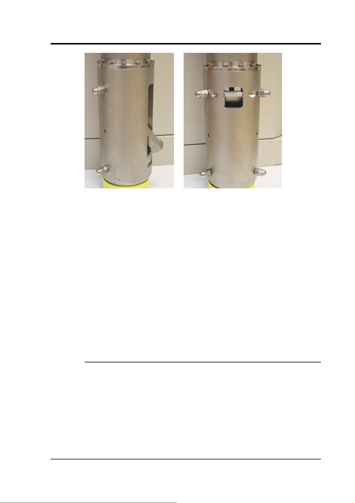
The single-jaw hole lock
The single jaw hole lock is the standard option for triaxial borehole
instruments. It consists of an active clamp arm and a number of skids
or studs on the sonde body. The arm is attached to a compression
spring, which forces it to swing out from the sonde and wedge the
body against the borehole wall. A serrated steel jaw at the end of the
arm provides maximum grip against the borehole casing. The skids or
studs and the locking arm together form a multi-point clamp, which
aligns the sonde body parallel to the axis of the borehole and holds it
firmly in place so that it cannot twist or slip under the influence of
ground vibrations.
There are several configurations of skids and studs which can provide
a suitable clamp. Either
• the locking jaw pushes two steel skids against the side of the
November 2006 7
Page 8
CMG-3TB
borehole, providing two line contacts;
• only the tips of the skids come into contact with the borehole,
providing three point contacts;
• a single skid is combined with a pad to provide one line and one
point contact; or
• three studs provide three point contacts.
8 Issue C
Page 9
Operator's guide
Studs have the advantage of being smaller than skids, but the contact
points are very close to each other. You should evaluate the various
locking methods available to see which works best in your borehole.
The spring inside the lock provides around 60 kg of force at its locking
position. A DC actuator retracts the arm into the body of the lock so
that the sensor mechanism can be installed and removed. The actuator
consists of a 14 W DC motor with a planetary reduction gearhead,
which drives the nut of a ball lead screw through the helical drive
gears. The thread of the lead screw is prevented from turning, and so
moves linearly when the nut turns.
The motor has a power system separate from that of the sensor, and
can be controlled from the surface using a hole lock control unit. Once
the sonde is installed, the hole lock control unit may be removed.
Without power, the hole lock will not be able to retract, and the sensor
will be secured.
The three-jaw hole lock
A three-jaw hole lock is available which gives better grip on the
borehole casing, but is bulkier and heavier than the single-arm lock.
This is the standard option for uniaxial instruments; it can be installed
in boreholes between 3.5” / 89 mm and 7” / 178 mm in diameter.
The three-jaw hole lock consists of a set of three active clamp arms
attached to a compression spring, which forces them to swing out from
the sonde and wedge themselves against the borehole wall. Serrated
steel jaws at the end of each arm provides maximum grip against the
borehole casing. This configuration ensures that the sonde body is
November 2006 9
Page 10
CMG-3TB
held parallel to the axis of the borehole and prevented from twisting or
slipping under the influence of ground vibrations.
10 Issue C
Page 11

Operator's guide
2 Assembling the instrument
2.1 Unpacking and packing
The 3TB seismometer is delivered in a single transportation case, with
the sensor system and hole lock mechanism (if ordered) packed
separately. The packaging is specifically designed for the 3TB and
should be reused whenever you need to transport the sensor. Please
note any damage to the packaging when you receive the equipment,
and unpack on a clean surface.
The package should contain:
• the seismometer, in sections;
• a cable to join the sensor to the breakout box;
• the breakout box;
• the hole lock control unit;
• a cable strain relief mechanism;
• a Handheld Control Unit (HCU) for monitoring sensor outputs
and calibration, if ordered; and
• a calibration data sheet.
The sensor is securely packed, and you will need to remove most of
the foam packing before it can be removed.
2.2 Handling notes
The 3TB is a sensitive instrument, and is easily damaged if
mishandled. It will not stand vertically upwards without support, and
should not be operated until it has been securely installed in a
borehole casing. If you are at all unsure about the handling or
November 2006 11
Page 12

CMG-3TB
installation of the device, you should contact Güralp Systems for
assistance.
• Do not bump or jolt any part of the sensor when handling or
unpacking.
• Keep the sonde sections vertical wherever possible. Carry them
by hand and store in a safe rack. Never drag or roll the sonde.
• Never lay the sonde horizontally whilst the sensors are
unlocked. If the sensor system topples over, you must inform
Güralp Systems.
• Keep all the parts of the sensor system protected and clean so
that they can be joined together securely. Store in the original
packaging if possible.
• Do not kink or walk on the data cable (especially on rough
surfaces such as gravel), nor allow it to bear the weight of the
sensor.
• Do not connect the instrument to power sources except where
instructed.
2.3 Assembling the 3TB
The 3TB is delivered in separate sections, which need to be assembled
before the instrument can be installed in a borehole. It is
recommended that you perform these steps with the help of at least
one other person.
Important: Make sure your environment is clean and dust free before
assembling the unit. Stray fibres or particles cause damage to the
“O”-ring seals between the components and may render the sensor
unusable. Do not remove the protective caps on the ends of each unit
until you are ready.
12 Issue C
Page 13
Operator's guide
1. Ensure that the “O”-ring seals on the hole lock and sensor
sections are clean and well greased.
2. Stand the horizontal sensor on the ground with the packing cap
at the top, and support it to prevent it from falling over. This can
be done either by using an assistant to hold the casing steady, or
by strapping it to a support such as a bench leg.
3. Remove the packing caps from the top of the horizontal sensor
and the bottom of the hole lock unit. Beneath the caps are
connectors for the horizontal components.
4. Hold the hole lock unit above the horizontal sensor and join the
November 2006 13
Page 14
CMG-3TB
connectors. Ensure that each is connected to its correct
counterpart.
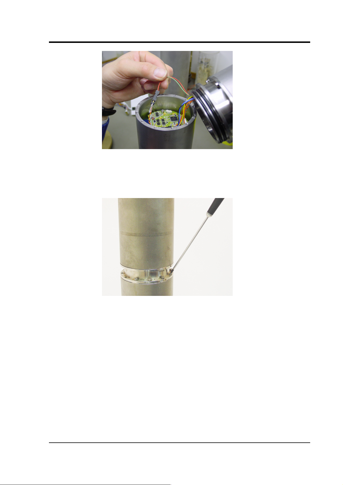
hole lock unit at an angle above the horizontal sensor and join
the connectors. Ensure that each is connected to its correct
counterpart. The wires are fairly short, so you will need a
second person to hold the instrument whilst you connect them.
Take care not to scratch the other components when attaching
the connectors.
5. Align the hole lock unit with the
NORTH
mark on the
horizontal sensor housing. Doing this will allow you to check
the approximate orientation of the sensors at a glance.
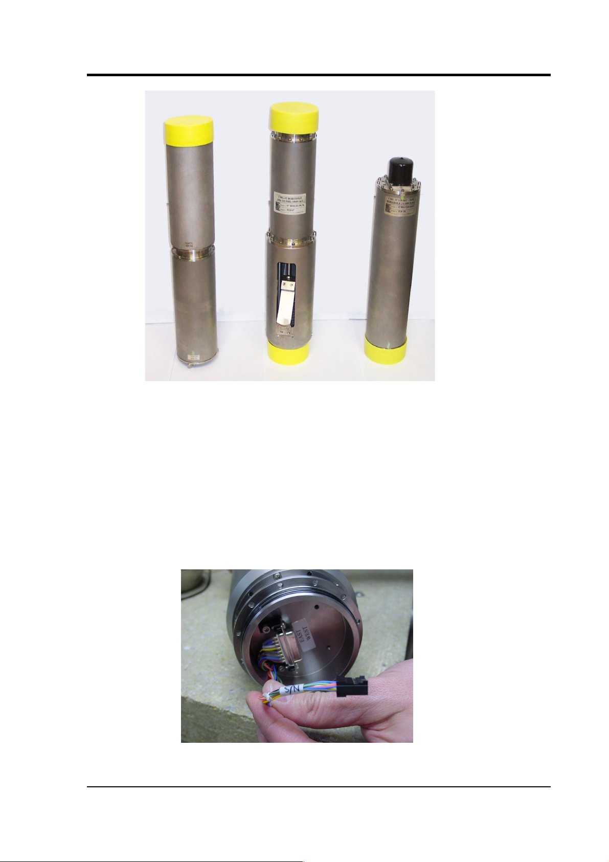
The horizontal sensor consists of two distinct units (the
north/south and east/west components), which are supplied
already joined together with M3 × 8 cap screws. You should not
need to undo this connection.
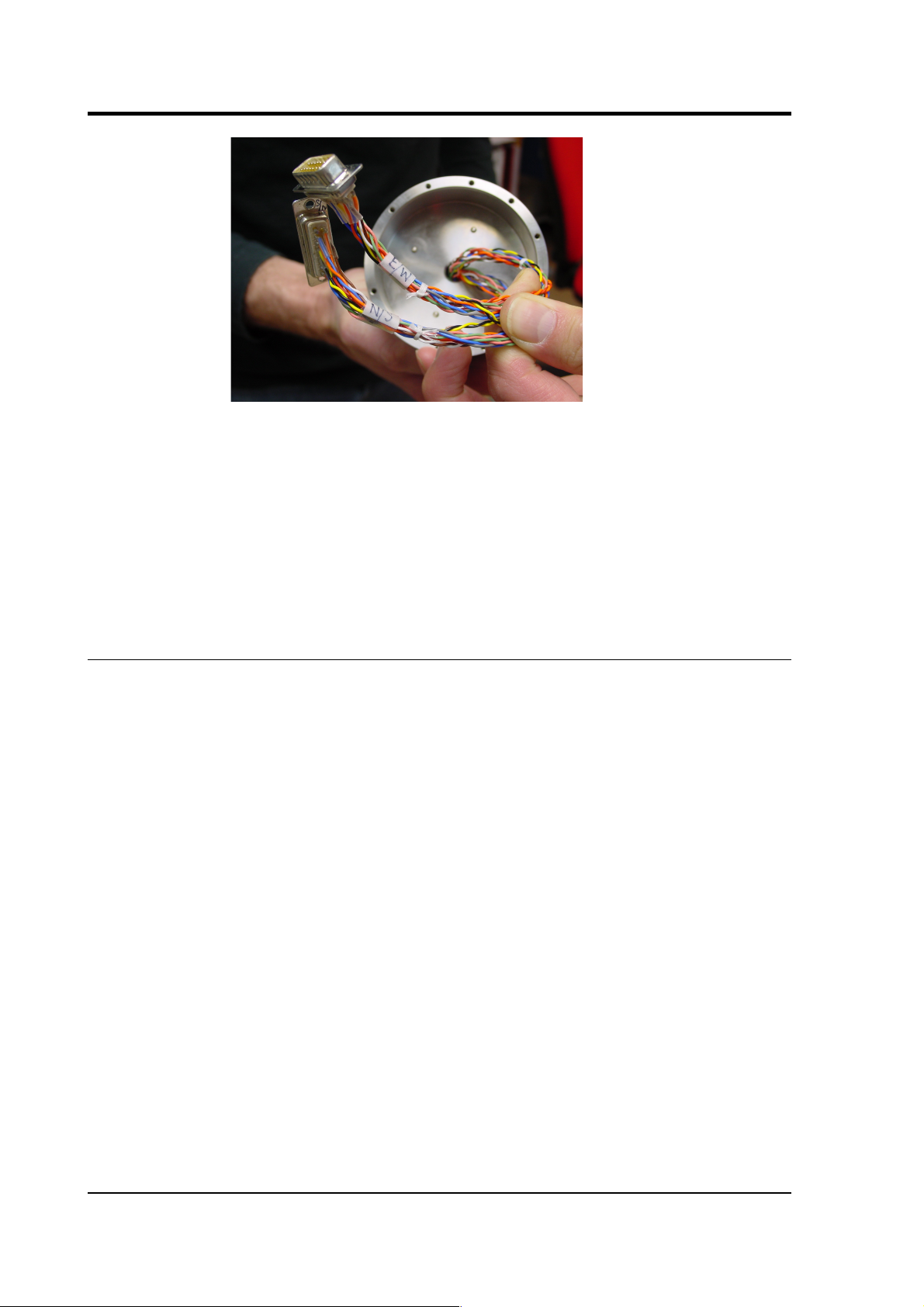
If you do separate the north/south and east/west components,
make sure that both the signal cable and, if present, the passthrough to the key switch (red and green, held in the
photograph below) are reconnected when you reassemble the
instrument.
14 Issue C
Page 15
Operator's guide
6. Push the hole lock unit into the horizontal sensor housing,
twisting to align the holes.
7. Fit twelve M3×8 cap screws into the holes in the joint flange.
8. When all twelve screws are fitted, begin to tighten them with a
ball-ended Allen screwdriver. Tighten evenly, working round
the instrument in several passes, until the two sections are
securely joined together.
9. The vertical sensor now needs to be attached to the other end of
the hole lock. Remove the packing caps from the top of the hole
lock–actuator section and the vertical sensor.
10.Hold the vertical sensor above the hole lock–actuator section
and connect the two 15-way “D”-type connectors, as before.
Ensure that each is connected to its correct counterpart.
November 2006 15
Page 16
CMG-3TB
11.Push the vertical sensor housing into the hole lock–actuator
section, twisting to align the holes.
12.Fit twelve M3×8 screws into the holes and tighten.
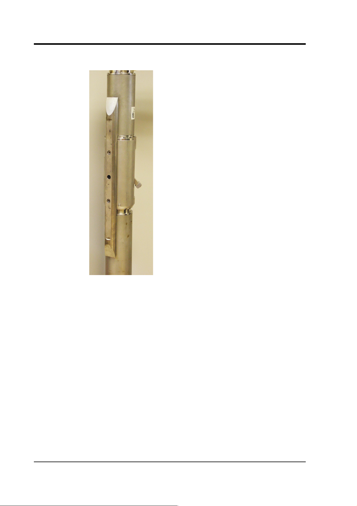
13.If you are using a single-jaw hole lock unit, attach skids or studs
to the sonde as appropriate for your installation, using the
fastenings provided.
2.4 Disassembling the instrument
When the instrument is recovered, you may want to disassemble it. To
do this, reverse the steps above, bearing in mind the following points:
• Make sure you only undo the screws that are necessary to
disassemble the instrument, and not the ones which hold each
module together. Each joint has several sets of screws holding it
together. Only one set from each joint needs to be undone—the
set which was added during assembly. For the joint between the
vertical sensor and the hole lock, this is the middle set of
screws; for that between the hole lock and the horizontal
sensors, it is the lower set. The joint between the two horizontal
sensors should not be dismantled.
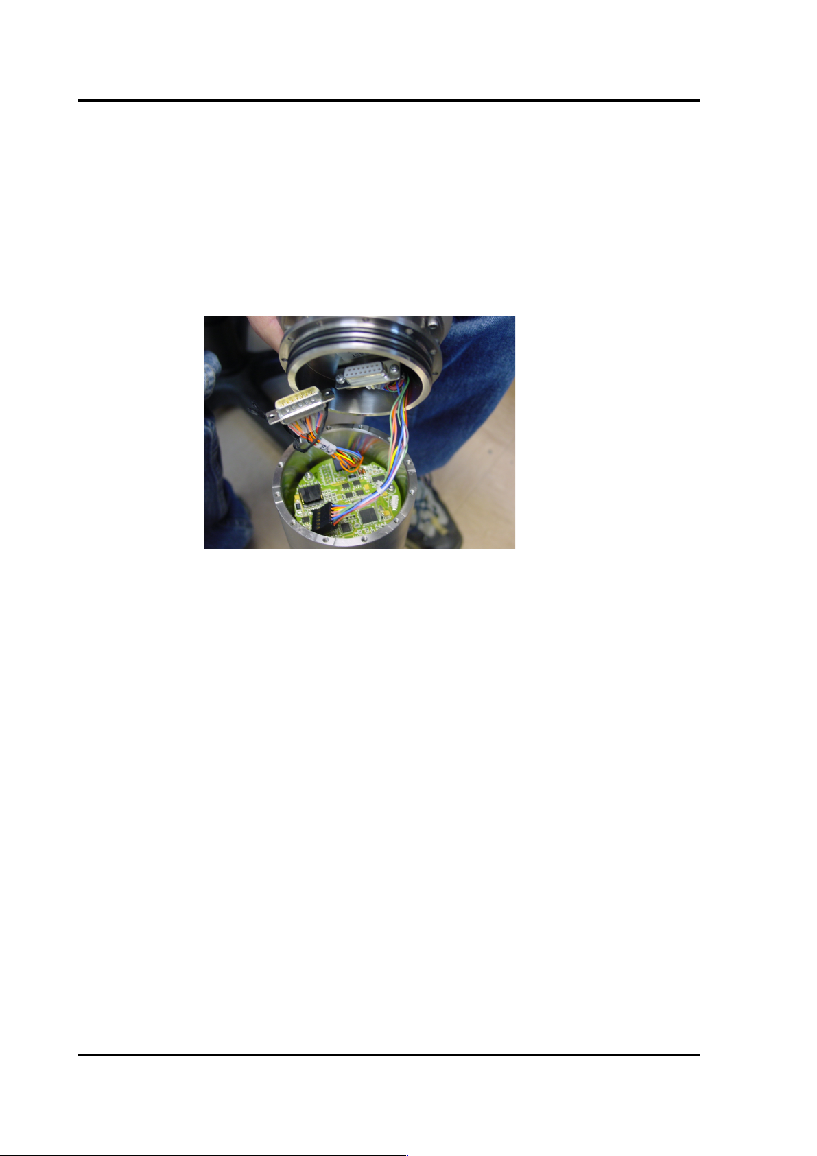
• When you detach one module from the next, do not yank them
apart, since doing this will damage the connectors inside. Insert
flat-head screwdrivers either side of the seal, and carefully lever
both sides up simultaneously so that the modules remain
parallel. You will need someone to support the upper module as
you do this.
When the two parts are separated, tilt the upper one to gain
access to the connectors, and disconnect them without
16 Issue C
Page 17
Operator's guide
scratching the other components.
2.5 Control units
The 3TB is operated from the surface through various control units. All
the 3TB's functions can be accessed through one or other unit. Most
can be removed from the site once the instrument is ready for use.
Some of these control units are optional and may not have been
supplied with your installation. Their functions can be duplicated
either by applying voltages directly to control lines (see appendixes for
pinout information) or through a connected Güralp digitizer such as
the CMG-DM24. The DM24 digitizer is able to pass commands to the
instrument from a Data Communications Module (DCM) or a computer
running Güralp Systems' Scream! software, allowing you to access all
of the instrument's functions remotely.
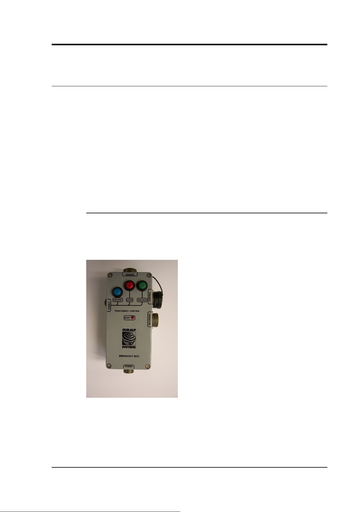
The breakout box
The breakout box is normally placed where the signal cable emerges
from the borehole. It provides connectors for attaching the various
other control units, supplies power to the instrument and relays output
signals to a recorder or digitizer.
• The
SENSOR
connector is a 32-way mil-spec plug, and should
be connected to the borehole instrument with the cable
provided.
• The
RECORDER
connector is a 26-way mil-spec plug. This
should be connected to an analogue data recorder or stand-alone
November 2006 17
Page 18

CMG-3TB
digitizer. In systems using downhole digitizers, this is replaced
by a 10-way mil-spec serial connector for attaching to a Data
Communications Module (DCM), modem or other
communications link.
• The
CONTROL
connector is a 26-way mil-spec plug intended
for connecting to an external controller or Handheld Control
Unit, with the same pin out as the
RECORDER
connector.
• The
POWER
connector is a 10-way mil-spec plug, which should
be connected to a source of 12 – 30 V DC power, for supplying to
the borehole instrumentation. When operating the hole lock,
you should connect the Holelock Control Unit to this connector.
Because of the high voltages employed, the hole lock circuitry is
entirely isolated from the rest of the electrical systems in the
sensor and surface unit; it is not usual to power the sensor
whilst using the hole lock.
For deep-borehole installations (over 50 m) we recommend that you
use a breakout box with internal line drivers, to ensure that logic
signals are reliably transmitted to the sensor. Contact Güralp Systems
for advice.
Note:
The breakout box looks very similar to other Güralp breakout
boxes. However, its internal wiring is different from that used for some
other instruments. For this reason, if you are using several instrument
types, you should mark each breakout box clearly so that it is always
used with the correct instrument.
Calibration
To calibrate the instrument, the
Calibration enable
line must be
activated. This operates a relay which allows a calibration signal to
flow through the transducer feedback coil. This provides an extra force
acting on the sensor masses, producing a corresponding deflection in
the output signal, which can be analysed by a control computer to
extract the seismometer's response characteristics.
Most Güralp instruments are manufactured with active-low
Calibration enable
lines. However, instruments with active-high
calibration can be manufactured on request.
Mass locking and unlocking
The 3TB is delivered with its sensor masses locked, so that they will
not be damaged in transit. You should lock the masses whenever you
18 Issue C
Page 19

Operator's guide
need to move the instrument.
To unlock the instrument, hold down the
ENABLE
and
UNLOCK
buttons (or the
UNLOCK
switch on a breakout box) for at least six
seconds. The sensor's microcontroller will free the vertical, N/S and
E/W sensor masses in turn and ready them for use. Once this is done,
the controller automatically starts a centring cycle. If you issue an
UNLOCK
command when the masses are already free, the instrument
will attempt to lock the masses first, and then unlock them in
sequence as normal.
To lock the instrument, hold down the
ENABLE
and
LOCK
buttons (or
the
LOCK
switch) for at least six seconds. The sensor's microcontroller
will lock the vertical sensor mass, followed by the N/S and E/W sensor
masses in turn. After this, the controller locks the base of the
horizontal instrument, tilting it until it is held against its end stop. The
instrument is now protected against accelerations up to 10g, and is
ready for transportation.
Centring
To centre the instrument, hold down
ENABLE
and
CENTRE
buttons
(or the
CENTRE
switch) for at least six seconds. If the masses are
locked, the microcontroller will do nothing. Otherwise, it attempts to
zero the output of the vertical, E/W, and N/S sensors in sequence by
exerting a small extra force on the boom. For the vertical sensor, a
motor-driven adjuster presses a small spring lever against the boom
until the mass position output indicates an offset close to zero. In the
case of the horizontal sensors, the sensor frame is tilted on its base
plate. Again, the controller monitors the mass position sensor and
stops the centring process once it reaches its lowest offset.
After successful centring, the mass position outputs should be in the
range 0.1 – 0.8 V. If the centring process leaves the mass position
outputs above ±1.1 V, start another centring cycle. You will probably
need to perform several rounds of centring before the masses are ready.
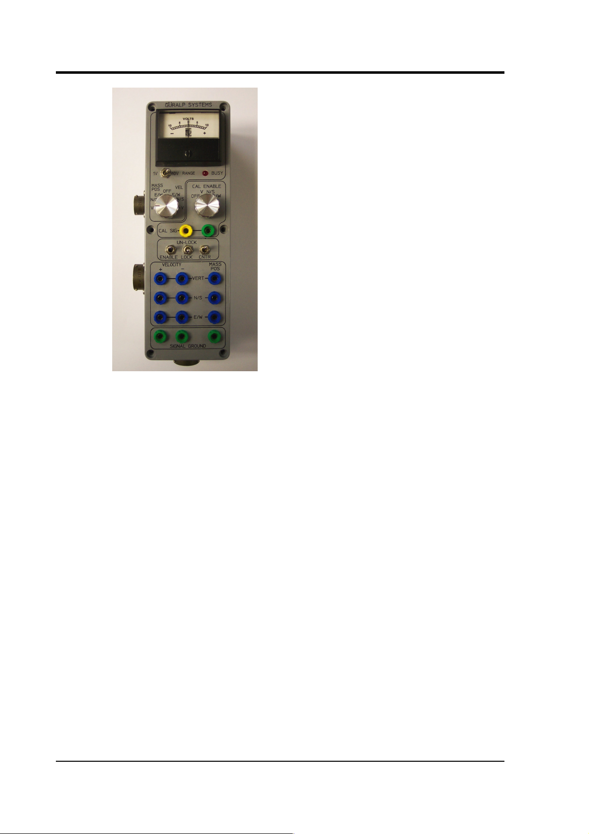
The handheld control unit
This portable control unit provides easy access to the seismometer's
control commands, as well as displaying the output velocity and mass
position (
i.e.
acceleration) on an analogue meter.
November 2006 19
Page 20
CMG-3TB
Connections
The HCU provides
• two identical 26-pin connectors for attaching to the
HCU
or
RECORDER
connectors of the breakout box, and
• a 10-pin connector through which you can power the
instrument, if desired. The power pins on this connector are
directly connected to those on the
SENSOR POWER
connector
of the breakout box. When using this alternative power
connection, you should ensure you do not inadvertently connect
two power supplies together.
Signal meter
The upper section of the HCU contains a simple voltmeter for
monitoring various signals from the instrument.
• To monitor the velocity outputs, switch the dial to
V, N/S
or
E/W VEL
according to the component you want to monitor.
• To monitor the mass position outputs, switch the dial to
V, N/S
or
E/W MASS POS
according to the component you want to
monitor.
20 Issue C
Page 21
Operator's guide
• You can set the range of the meter with the
RANGE
switch.
When switched to 10 V, the meter ranges from –10 to +10 V (as
marked.) When switched to 1 V, the range is –1 to +1 V.
Calibration and control
You can calibrate a 3TB sensor through the HCU by connecting a
signal generator across the yellow and green
CALIBRATION SIGNAL
inputs and turning the
CAL ENABLE
dial to the component you wish
to calibrate. The sensor's response can now be monitored or recorded,
and calibration calculations carried out.
The section of the HCU below the calibration lines controls the
instrument's mass control system. To initiate locking, unlocking, or
centring, hold down the
ENABLE
switch on the HCU
together with
the
appropriate switch for the command you want to issue for at least six
seconds.
Banana plugs
The remainder of the HCU provides useful connections for each of the
signal lines from the instrument, for attaching to your own equipment
as necessary.
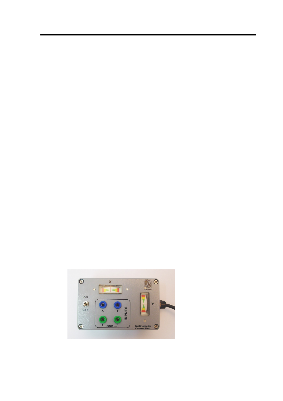
The inclinometer monitor unit
The borehole sensor system can operate successfully in boreholes with
a tilt angle up to 3.5 °. To check that the instrument is installed
suitably close to the vertical, a two-axis inclinometer is installed
within the sensor housing. The inclinometer monitor unit is used as a
visual guide to the sensor's tilt only, and should not be used if precise
attitude information is required. You should check the inclination of
the instrument
before
unlocking the sensor masses, since too great a
tilt can damage the components.
November 2006 21
Page 22
CMG-3TB
To measure the attitude of a 3TB instrument:
1. Connect the inclinometer monitor unit to the
CONTROL
connector of the breakout box.
2. Switch the
ON/OFF
switch on the monitor unit to the
ON
position. The inclinometer is powered separately from other
parts of the system; this switch provides power to the downhole
circuitry as well as to the monitor unit. The inclinometer should
not normally be powered up whilst the sensor is in use.
3. Read off the X and Y components of the tilt from the analogue
meters.
4. If both tilts are within the green shaded region, the instrument is
close enough to vertical that it can be levelled and centred
successfully. If either output is in the red shaded region, you
should
not
attempt to unlock or centre the sensor masses.
Instead, if possible, you should move the instrument within the
borehole to a place where it can lie closer to vertical.
If you need to use the outputs of the inclinometer for some other
purpose, you can also connect a multimeter to the banana sockets on
the inclinometer monitor unit.
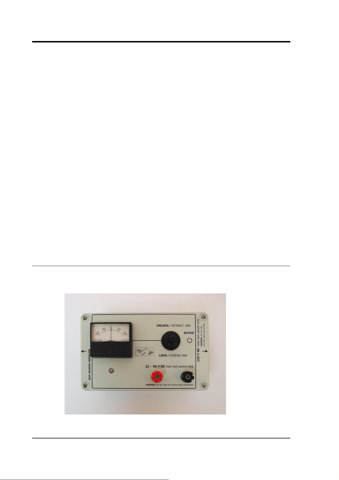
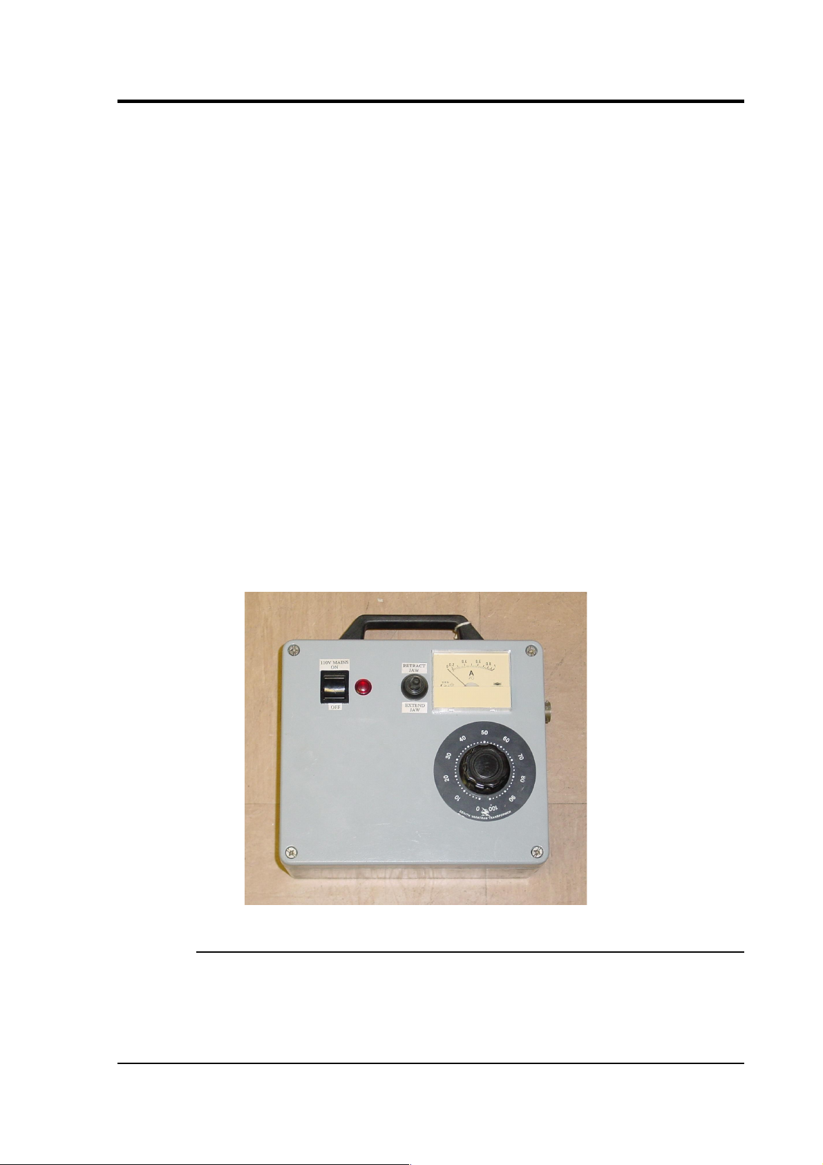
2.6 Operating the hole lock
The hole lock, if fitted, can be extended and retracted using the hole
lock control unit:
22 Issue C
Page 23
Operator's guide
Caution: The hole lock may be using high-voltage mains (outlet)
power.
1. Connect the hole lock control unit to the
HOLELOCK POWER
connector of the breakout box, and to a mains power supply.
Alternatively
, connect a 12 – 24 V DC power supply across the
input terminals of the hole lock control unit.
Do not connect
both DC and mains power at the same time.
The hole lock control unit supplied in regions with 220 V AC
mains power differs from that supplied for 110 V AC mains
power. You should ensure that you provide the correct voltage
to the hole lock control unit, otherwise damage may result to the
sensor.
2. Open the
MASS LOCK / UNLOCK – POWER ON / OFF
flap on
the breakout box, and set the sensor power switch to the
off
position. The hole lock will
only
function whilst the power is
off, to avoid injecting current transients from the mains power
supply into the sensor electronics.
3. If you are using a deep-borehole hole lock control unit, set the
dial to zero.
Engaging the hole lock
To extend the jaw of the hole lock:
1. Hold the switch on the hole lock control unit in the
EXTEND
JAW
or + position. If you are using a deep-borehole control
November 2006 23
Page 24

CMG-3TB
unit, there will be an additional dial compared to the unit
pictured; turn this until the built-in ammeter reads around 0.1
A.
2. When the arm makes contact with the borehole casing, the
current will drop slightly. Continue holding the switch in the
EXTEND JAW
position.
3. When the lock arm reaches its fully extended position, the
motor will automatically stop and the current will drop to 0 A. If
using a deep-borehole unit, return the dial to zero.
4. If the current has not dropped quite to zero after 30 – 40 s of
operation, release the switch, wait a few seconds, and push it
back to the
EXTEND JAW
position briefly. If the arm is not
completely extended, you will see a surge of current. If the
current remains constant, the jaw is at its maximum reach.
5. Once the sensor is locked in place, it is recommended that you
remove the hole lock power cable and control unit from the site.
Without power, the hole lock will not be able to retract, and the
sensor will be secure.
Disengaging the hole lock
To retract the jaw of the hole lock:
1. Tension the load bearing cable, to take up any slack.
2. Hold the switch on the hole lock control unit in the
RETRACT
JAW
or – position. If using a deep-borehole control unit, also
turn the dial until the built-in ammeter indicates 0.3 – 0.5 A.
More current is drawn retracting the arm, because the motor is
now working against the spring.
3. When the lock arm reaches its fully retracted position, the
motors will automatically stop and the current will drop to 0 A.
If using a deep-borehole unit, return the dial to zero.
Manual operation
If you prefer, you can operate the hole lock by applying voltages
directly to the sensor.
• To extend the jaw, connect the
Hole Lock Motor
pin on the
sensor (or on the breakout box's
HCU
or
RECORDER
connectors)
to a +12 V power source, and the
Hole Lock Motor Return
pin to
24 Issue C
Page 25

Operator's guide
0 V.
• To retract the jaw, reverse the polarity so that the
Hole Lock
Motor Return
pin is at +12 V and the
Hole Lock Motor
pin is at
0 V.
November 2006 25
Page 26

CMG-3TB
3 Installing the 3TB in a borehole
Before installing any instrument in a borehole, you should prepare the
installation site.
• Clean the area around the borehole head, so there is clear access
all around it.
• Keep the borehole capped at all times except when inserting or
removing the instrument, so that debris and tools do not
accidentally fall in.
• Lay out the cables beside the borehole, or set up a cable drum
nearby, so that they do not become tangled.
• Ensure the tripod is tall enough to hang the entire installation
(sensor and strain relief unit or digitizer) from it, with the sensor
off the ground.
• Use a winch with a depth gauge if possible, or measure out the
cable beforehand.
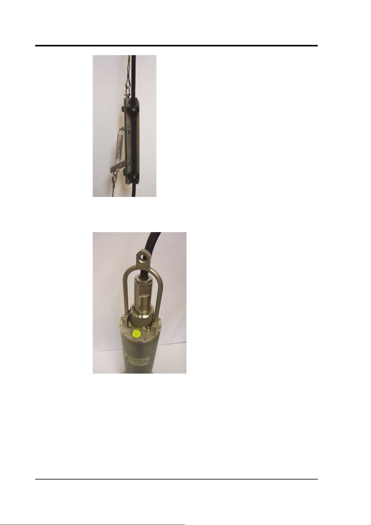
Most installations are equipped with a strain relief unit, which
consists of a metal arm that swings out from the load-bearing cable to
wedge against the side of the borehole. This removes any strain in the
load-bearing cable and prevents vibrations from the surface from being
transmitted to the instrument. In installations with a downhole
digitizer, the strain relief arm is fitted to the base of the digitizer sonde;
the phrase “strain relief unit” in the following instructions should be
taken to refer to the digitizer's strain relief arm.
3.1 Installing a sensor with hole lock unit
1. Connect the signal cable to the connector on top of the sensor.
Ensure that the “O”-rings inside the housing are clean, and
tighten the knurled connector nut to its end stop.
26 Issue C
Page 27

Operator's guide
2. If applicable, you should test the hole lock mechanism before
installing the sensor. For safety reasons, the hole lock is
normally supplied with the arm extended.
To test the mechanism, connect the signal cable to a breakout
box and Holelock Control Unit, and attempt to retract the hole
lock arm (see Section 2.6, page 22.) If this fails, you should
contact Güralp Systems. Extend the arm once more.
3. Fix the main lifting cable to the shackle on top of the strain
relief mechanism, and run the signal cable through the
mechanism using the built-in clamps (without tightening them.)
Do not allow the signal cable to bear any of the sensor's weight.
November 2006 27
Page 28
CMG-3TB
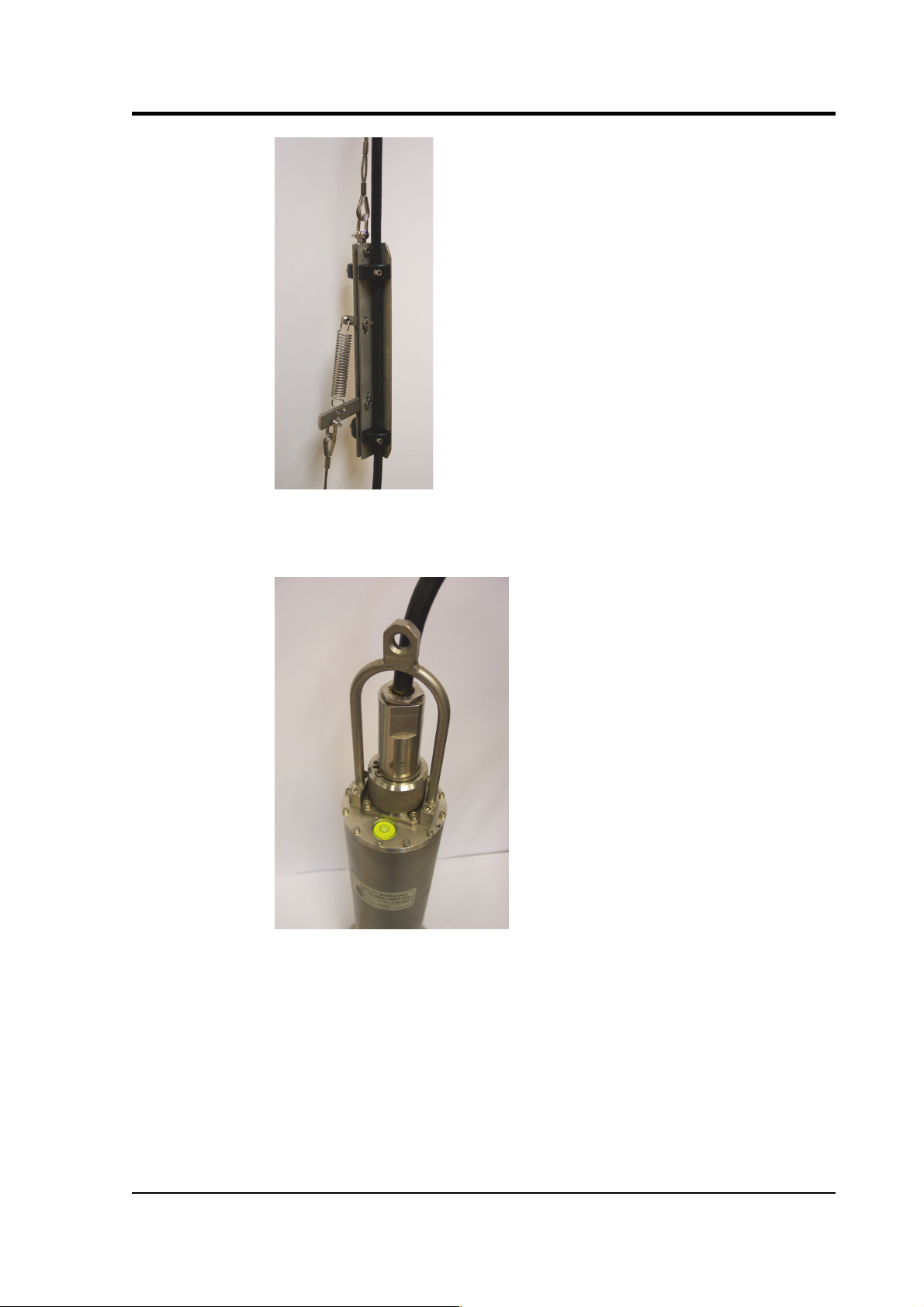
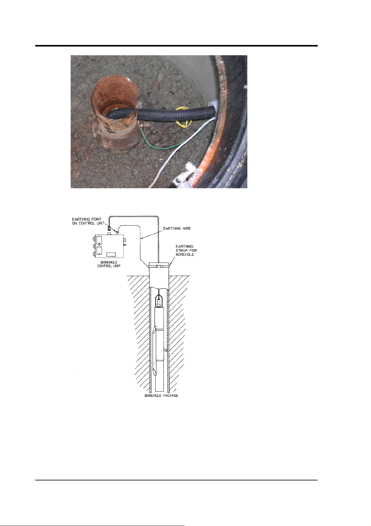
4. Attach the lifting loop to the sensor using four M5×16 screws
(provided).
5. Join the loop to the bottom of the strain relief mechanism using
the linking cable provided.
6. Using a small winch, hoist up the sensor package and strain
relief mechanism until both are hanging by the lifting cable,
with the strain relief mechanism extended. Tighten the cable
clamps on the strain relief unit, allowing a little slack in the
signal cable.
28 Issue C
Page 29

Operator's guide
7. Fix the signal cable to the main lifting cable about 1 m above the
strain relief mechanism using a metal clamp (a nylon cable tie
may be sufficient for shallow installations.) Leave a little slack
in the signal cable between the clamp and the strain relief
mechanism.
8. Position the assembly over the top of the borehole. Do not allow
it to drag across the ground.
9. Lower the sonde so that its base is just level with the borehole
mouth. If there is a depth gauge on the winch, set this to zero.
10.Continue to lower the sonde to a depth of about 1 m, so that the
instrument is still visible.
11.Extend the hole lock arm (see Section 2.6, page 22) to check
that it fits your borehole. The current drawn should dip slightly
as the arm touches the casing, then drop to zero when it is fully
extended. Check that the sonde is firmly anchored to the
borehole casing by attempting to slacken the load bearing cable.
If it remains taut, the sonde is still loose within the borehole. Do
not proceed with installation in this case. Instead, you should
either move the instrument to a narrower section of the borehole
and try again, or contact Güralp Systems to fit a longer hole
lock, quoting accurate measurements of your borehole.
12.Power up the instrument from a suitable power supply.
13.Level and centre the sensor (see Section 3.5, page 46) so that it
can be tested.
14.Check that the sensor is functioning correctly by connecting a
meter or monitoring device to the sensor outputs. If the sensor
November 2006 29
Page 30

CMG-3TB
fails to register ground movements, contact Güralp Systems.
15.Lock the sensor masses once more, tension the load bearing
cable and retract the hole lock arm.
16.Gently lower the sensor to the required depth. At approximately
20 m intervals, fix the signal cable to the load bearing cable
using metal clamps (nylon cable ties every 5 m may be sufficient
for shallow installations). This will ensure that the signal cable
does not become kinked or trapped within the borehole. Leave a
little slack on the signal cable each time, so that it does not bear
any weight. Too much slack, however, will cause the cable to
scrape against the borehole casing.
17.Fix the sensor system into the borehole using the hole lock arm
(see Section 2.6, page 22).
If you are installing a 3TB in a deep borehole, the weight of the
sensor will stretch the load bearing cable slightly. Remember to
allow for this when raising or lowering the cable in the
following steps.
18.Use the winch to drag the assembly up within the borehole for a
distance of 15 – 30 cm. This will ensure that the hole lock arm
and the skids or studs on the sonde keep the sensor package
vertical within the borehole. Do not drag too far, or you will
damage the contact points.
19.Lower the load bearing cable by around 30 cm to engage the
strain relief unit inside the borehole casing, and to provide some
slack in the cables.
20.Clamp the load bearing cable to the top of the borehole.
21.Tie the lifting and signal cables together above the strain relief
mechanism using tie wraps.
22.The sensor can now be levelled and unlocked ready for use.
30 Issue C
Page 31

Operator's guide
3.2 Installing a sensor using sand backfill
Dry sand backfill is a convenient and effective way of installing a
borehole or posthole sensor in a time-stable environment. The
presence of sand not only fixes the sensor in place at the bottom of the
hole, but also reduces noise due to air convection.
The ideal type of sand to use is the fine, kiln-dried sand used for
children's play sandpits. This is readily available in airtight bags, is
thoroughly washed and clean, and will contain little sediment. (When
dried out after wetting, sand containing foreign matter may solidify
and “concrete” the sensor in position.) This sand is suitable for use in
both dry and damp boreholes.
In the procedure outlined below, the sensor rests on a pad of sand
around 300mm thick. This pad will absorb any residual moisture at
the bottom of the borehole, and ensure that the surroundings of the
instrument are kept dry.
After positioning the sensor, more sand is added to fill the space
between it and the borehole casing, holding it firmly in place. The
sand should reach within 30mm of the top of the instrument, but
should not cover it. This way, the instrument can be more easily
recovered when it requires maintenance or replacement. This is
particularly important if the borehole is not completely dry, since
moist sand does not flow well.
The following photographs show the steps involved in backfilling with
sand:
November 2006 31
Page 32

CMG-3TB
Procedure
To install a sensor at the bottom of a borehole of known depth using
sand backfilling:
1. Measure or calculate the physical volume of the unit which is to
be installed in the borehole. (The volume of a cylinder
v =
πr2h
.) Also measure the internal diameter of the borehole.
2. Measure and pour in a sufficient quantity of sand to fill the
borehole to a depth of around 300mm.
3. Connect the signal cable to the connector on top of the sensor.
Ensure that the “O”-rings inside the housing are clean, and
tighten the knurled connector nut to its end stop.
4. Fix the main lifting cable to the shackle on top of the strain
relief mechanism, and run the signal cable through the
mechanism using the built-in clamps (without tightening them.)
Do not allow the signal cable to bear any of the sensor's weight.
32 Issue C
Page 33
Operator's guide
5. Attach the lifting loop to the sensor using four M5×16 screws
(provided).
6. Join the loop to the bottom of the strain relief mechanism using
the linking cable provided.
7. Hoist up the sensor package and strain relief mechanism until
both are hanging by the lifting cable, with the strain relief
mechanism extended. Tighten the cable clamps on the strain
relief unit, allowing a little slack in the signal cable.
November 2006 33
Page 34

CMG-3TB
8. Fix the signal cable to the main lifting cable about 1 m above the
strain relief mechanism using a metal clamp (a nylon cable tie
may be sufficient for shallow installations.) Leave a little slack
in the signal cable between the clamp and the strain relief
mechanism.
9. Position the assembly over the top of the borehole. Do not allow
it to drag across the ground.
10.Lower the sensor so that its base is level with the borehole
mouth. Set the depth gauge on the winch to zero.
11.Calculate how much lifting cable must be lowered into the
borehole, taking into account the length of the sensor and the
strain relief assembly or digitizer.
If you are installing a 3TB in a deep borehole, the weight of the
sensor will stretch the load bearing cable slightly. Remember to
allow for this when raising or lowering the sensor in the
following steps, since allowing the instrument to strike the
bottom of the borehole will damage it.
12.Begin lowering the sensor down the borehole, keeping track of
the depth reached.
13.At approximately 20 m intervals, fix the signal cable to the load
bearing cable using metal clamps (nylon cable ties every 5 m
may be sufficient for shallow installations). This will ensure
that the signal cable does not become kinked or trapped within
the borehole. Leave a little slack on the signal cable each time,
so that it does not bear any weight. Too much slack, however,
will cause the cable to scrape against the borehole casing.
34 Issue C
Page 35

Operator's guide
14.Whilst monitoring the depth of the sensor, carefully approach
the sand layer at the bottom of the borehole. The lifting cable
will go slack when the sensor makes contact with the sand.
If the lifting cable goes slack before the sensor has reached the
sand layer, it may have become caught on a bad joint or lip in
the borehole; carefully raise and lower the instrument to free it.
15.When you have reached the bottom, use the winch to lift the
package slightly, taking the slack off the cable. This ensures that
the sensor is hanging vertically within the borehole, and is no
longer in contact with the sand bed.
At this point, you may wish to use an inclinometer monitor unit
to check that the instrument is sufficiently close to vertical to be
properly centred. See section 3.5, page 46, for details.
16.Calculate the volume of dry sand required to fill the gap
between the sensor and the borehole liner to the level of the top
of the sensor (
v = πr2h
using the internal radius of the borehole,
less the volume of the instrument determined in step 1.)
17.Pour this sand into the borehole. If you can, check how much of
the sensor is covered with sand. Do not overfill the hole.
18.Carefully slacken the load bearing cable. This will engage the
locking arm of the strain relief mechanism and secure the
installation within the borehole.
19.Without pulling or lifting the sensor, lightly shake the cables to
remove any sand that may have fallen onto them or onto the
strain relief mechanism.
20.Clamp the load bearing cable to the top of the borehole, and
remove the winch.
21.The sensor can now be centred and unlocked ready for use.
November 2006 35
Page 36

CMG-3TB
3.3 Assembling the winch
If required, Güralp Systems can provide a winch suitable for installing
a borehole sensor. The winch and tripod are supplied as a set of parts
which you can assemble on site:
There are two sections for each leg of the tripod. The upper sections
are pre-attached to the head of the tripod; the lower sections are
supplied detached.
1. Slide the lower sections all the way into the head with the
retaining tape loops facing outwards.
2. If you are working on a surface of
sand
or
soil
, rotate the feet so
that the points face downwards (left). For
rock
or other hard
surfaces, ensure the pads face downwards (right).
36 Issue C
Page 37

Operator's guide
3. Erect the tripod above the borehole, and run the yellow
retaining tape through the loops. Fasten together the ends of the
tape.
4. The lifting cable is supplied with a loop at one end. Run this
over one of the pulleys at the top of the tripod, so that the loop
hangs down between the legs. If the loop is not provided, you
can make one by untwisting three outer strands from the (7core) cable, crossing the two sets, and pleating the three outside
strands back around the remaining four in the opposite
direction. Secure the loop with a cable clamp.
5. Run the sensor signal cable through the other pulley. Secure
both cables in their pulleys by sliding the attached bolts into
place.
6. Extend each of the three legs in turn to the height you require,
November 2006 37
Page 38

CMG-3TB
finishing at the leg with the winch attached.
7. Take the end of the load-bearing cable without the loop, and
screw it to the axle inside the winch using a 4 mm Allen key
(provided) as shown.
8. Attach the handle to the side of the winch
opposite
the ratchet
mechanism, and fasten it in place with a collar, washer and
screw, using the larger Allen key.
38 Issue C
Page 39

Operator's guide
9. Wind the cable onto the winch by rotating the handle. Ensure
that the cable builds up neatly across the drum. Continue
winding until the loop on the other end is as high as you need it
to install the equipment.
If the ratchet prevents you from winding the cable on, twist the
metal boss in the
DOWN
direction to free the cable.
10.Remove the handle, and screw it onto the metal spool of the
ratchet mechanism.
November 2006 39
Page 40

CMG-3TB
11.Hang the strain relief unit and instrument(s) from the loop at
the other end of the cable. You are now ready to lower the
assembly into the borehole as described above.
3.4 Earthing a borehole sensor
To achieve the best performance from any borehole instrument, you
must make sure that the sensor electronics, its casing and the power
supply share a common, local ground, and that all power and data
lines are adequately protected against lightning and other transients.
This section describes techniques for grounding sensor equipment
which have proved effective in many installations. However, local
conditions are always paramount, and you should design your
installation with these in mind. Any regulations in force at your
chosen location must also be followed.
Installations with AC power supplies
If you are using mains (outlet) power, or some other AC power
distribution system, we recommend installing a fully isolating
transformer between it and the power supply for the instrument. This
will allow full control of the local grround.
A spark-gap surge protector should also be installed on the mains side
of the transformer, so that transient overvoltages are not transmitted
across it. Suitable protectors are available off the shelf from several
suppliers. On the sensor side, surge protection is installed as standard
within all new Güralp borehole sensors and control equipment. If your
surface installation includes third party electronics, digitizers, etc., you
may need to install additional protection where power and data lines
enter the surface enclosure. Contact Güralp Systems if you are unsure.
Within the installation, a single ground point should be established,
40 Issue C
Page 41

Operator's guide
which is connected to a local ground plate. All earth lines for
equipment in the installation, such as the casings of the transformers
and of the sensor electronics, as well as the signal ground line from the
sensor, should be connected to this plate.
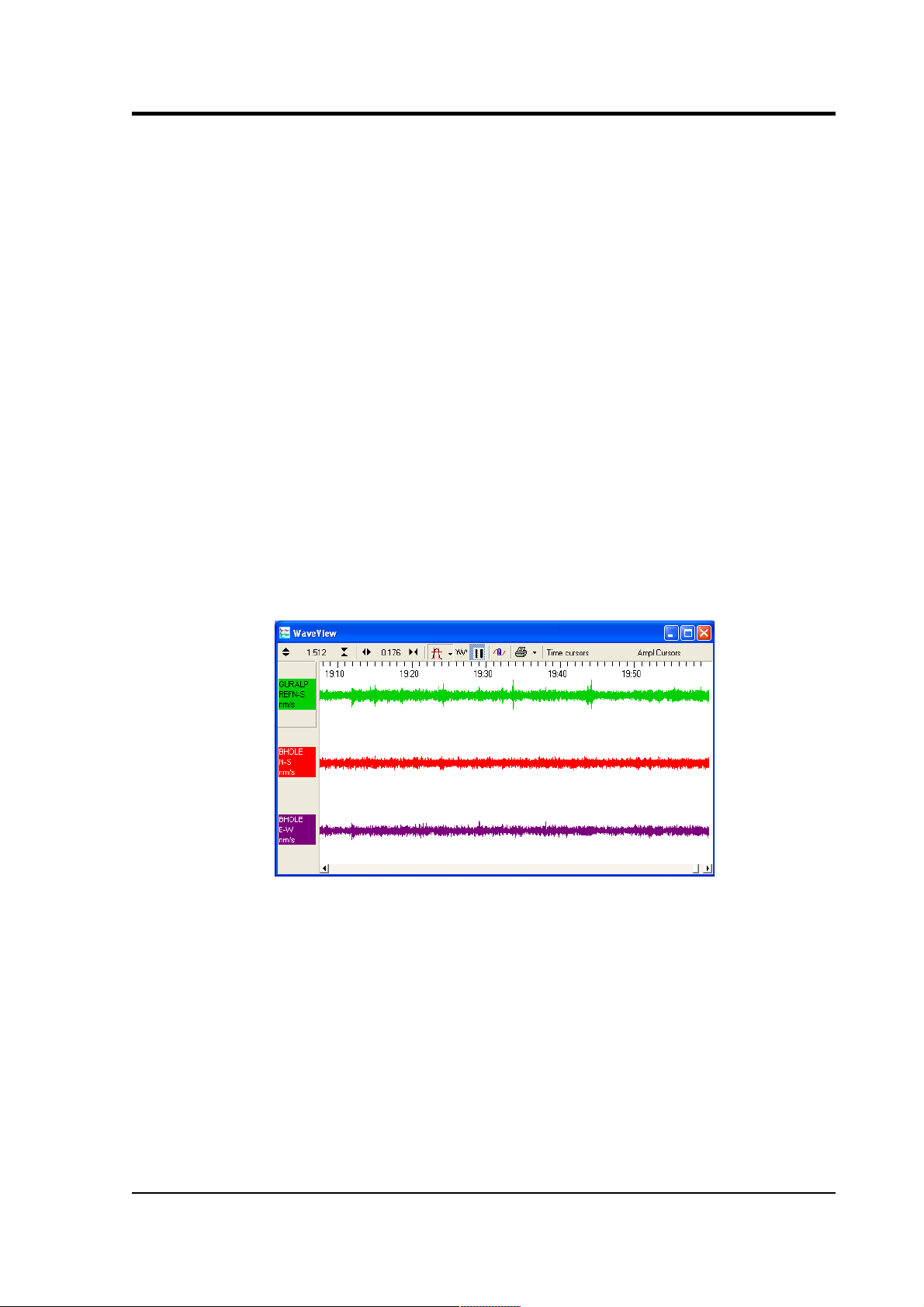
The best local earth point in many installations is the borehole itself.
For this to work, the borehole must have a conductive casing and be
situated close (<30 m) to the surface installation. In such an
installation you need only connect a cable (green wire in the
photograph below) from the local ground plate to the borehole casing.
November 2006 41
Page 42
CMG-3TB
An earth strap can be used to ensure a good connection.
If the lower borehole is filled with salt water, the instrument will be
adequately grounded without any further action. Fresh water is an
inferior conductor.
In a dry or sand-filled borehole, or one with a non-conducting casing,
you will need to ensure the sonde is grounded by some other means.
42 Issue C
Page 43

Operator's guide
The best option is often to attach the sensor housing to an earth line
brought out to the surface and attached to a metal stake driven into the
ground nearby.
The sensor's load bearing cable is suitable for this purpose, provided it
is secured to the sensor's lifting loop with a metallic clamp as shown
below. This provides an additional firm contact between the sonde and
the load-bearing cable. Installations with downhole digitizers will need
similar arrangements at the top and bottom of the digitizer module, or
a separate cable for this purpose.
November 2006 43
Page 44

CMG-3TB
For boreholes with a metallic casing at the bottom and plastic above,
we recommend connecting a cable between the sensor housing and the
ground plate so that the lower borehole casing acts as the earthing
point. Again, the
If there is a significant distance (>30 m) between the borehole and the
surface installation, the resistance of the earth cable may make it
impractical to use the borehole as an earthing point. In these cases,
you will have to connect the local ground plate to an earth stake near
to the enclosure; any coupling between this sensor-local earth line and
ground lines for other parts of the system must be minimized.
Installations with DC power supplies
Güralp sensors require a 24 V DC power supply. In most cases, this is
provided by an isolating DC/DC converter installed at the surface. This
converter can be earthed to the local ground plate as above.
However, DC/DC converters contain sensitive electronics, which must
be protected thoroughly. We recommend installing a full surge
protection unit in addition to the spark gap protector. This protection
is installed on the supply side of the isolator, so it must be earthed
separately
from the borehole installation. Otherwise, transients in the
power supply will couple to the sensor.
44 Issue C
Page 45

Operator's guide
As with AC installations, if the borehole is more than around 30 m
from the surface enclosure, you will need to provide a second earthing
point for the local ground plate.
DC power is most commonly available at self-contained installations
with power supplied from batteries, solar panels, or a wind generator.
In these cases, the power supply may already have protection from
transients installed, in which case you may not need such
comprehensive protection (although some form of protection is
always
necessary.)
External lightning protection
The surface installation building, and if possible the borehole also,
should be protected by lightning conductors. These should lead to
ground well away from the borehole. As a rule of thumb, a lightning
mast provides a “zone of protection” within a 45 ° cone the height of
the mast.
If you are using two earthing points, for example in the DC installation
shown above, it may be convenient to connect the lightning conductor
to the supply-side earthing point. In any case, the lightning earth must
be well separated from the borehole (and its earth, if it needs one.)
November 2006 45
Page 46

CMG-3TB
3.5 Levelling and centring
Once it is installed, you should level and centre the instrument ready
for use. This can be done using the various surface control units:
1. Connect an inclinometer monitor unit to the breakout box.
2. Turn on the borehole control unit using the
ON/OFF
switch
under the transparent flap.
3. Turn on the inclinometer monitor unit using its
ON/OFF
switch,
and read off the
X
and Y components of the tilt from the
analogue meters.
4. If both tilts are within the green shaded region, the instrument is
close enough to vertical that it can be levelled and centred
successfully. If either output is in the red shaded region, you
should
not
attempt to unlock or centre the sensor masses.
Instead, if possible, you should move the instrument within the
borehole to a place where it can lie closer to vertical.
5. Connect a handheld control unit (HCU) to the sensor control
unit, if you have one.
6. Unlock the sensor masses, either by pushing the
UNLOCK
buttons of the borehole control unit, or by holding down the
ENABLE
and
UNLOCK
switches of the HCU together for at least
six seconds.
7. When you press the switches, the
BUSY
LED will come on.
After a while, the unlocking process will be completed, and the
instrument will start centring itself. Whilst this happens, the
BUSY
LED will flash.
8. Monitor the outputs of the mass positions, either using the HCU
or your recording system. The microcontroller inside the unit
will zero the outputs from the vertical, N/S and E/W sensors in
sequence. After successful centring, the mass position outputs
should be in the range 0.1 – 0.8 V.
9. If the centring process leaves the mass position outputs above
±1.1 V, repeat steps 4 and 5. You will probably need to initiate
the centring process several times before the masses are
adequately centred.
46 Issue C
Page 47

Operator's guide
3.6 Downhole orientation
Once the sensor is installed inside the borehole, you will need to
measure its orientation with respect to the compass points. There is no
need to rotate the sensor itself, since the data can be rotated
algorithmically after it is digitised.
A simple method for determining the orientation of a sensor package
using the sensor's own horizontal component sensors, has been used
effectively by the Blacknest Seismological Centre, UK, with downhole
and surface equipment from Güralp Systems (
AWE Report O 10/93
,
1993.)
In this experiment, signals received by the N/S component of the
reference sensor are correlated with those received at the N/S and E/W
components of the sensor being studied, after different amounts of
mathematical rotation. The highest correlation will occur when the
N/S component of the reference sensor matches the rotated N/S
component of the borehole sensor.
Once you know the deviation of the borehole components from the
compass points, you can instruct the digitizer to rotate the signals
algorithmically.
Installing the Scream! extension
The
Relative Orientation
extension is supplied in the standard
Windows distribution of Scream! 4.2 and later.
The extension uses Matlab libraries, which are currently only available
for Windows. However, you do not need the full Matlab package to use
the extension. The Matlab runtime libraries are also included in the
Scream! distribution.
Installing the reference instrument
To measure the orientation of a sensor, you will need a second
instrument which is known to point precisely North. It should be
located on a solid surface as close to the other instrument as possible.
Most boreholes are constructed with a concrete base around the top of
the borehole. If this is present, we recommend installing the reference
sensor there.
Ideally, the two sensors will be directly connected to the same 6channel digitizer. If you are using separate digitizers, you will need to
ensure they are
exactly
synchronized. This can be done by connecting
GPS receivers to both digitizers and waiting for the control system of
November 2006 47
Page 48

CMG-3TB
each one to settle. This process takes at least 12 hours.
Measuring the orientation
1. Run Scream!. Open the
File – Setup
window, and select the
Display
tab.
2. Under
Stream Buffering
, increase the buffer size to an amount
which will hold all your experimental data. Click OK.
3. Drag the data files you have recorded into Scream!. A
Replay
Control
window will open.
4. Click the
Increase Speed
icon until the legend (
128x
in the
picture above) reads
Max
.
5. Click the
Pause
icon to begin replaying.
Scream! will be able to replay data faster if you are not currently
displaying it. When Scream! has finished, the
Replay Control
window will disappear.
6. Hold down CTRL and select the N, E, and X streams from the
digitizer at the correct sample rate.
48 Issue C
Page 49
Operator's guide
The N and E streams are the “North/South” and “East/West”
components of the downhole instrument. The X stream is the
North/South component of the reference instrument.
If you are using a separate digitizer,
the reference instrument
will appear on the North/South component of the other digitizer,
instead of the X stream. To select this at the same time as the
other streams, make sure
Network
is selected in the left-hand
pane of Scream!'s main window, to display all the streams from
your seismic network.
7. Double-click on one of the selected streams, or press ENTER. A
WaveView
window will open.
8. Drag the streams across the window so that the reference stream
is at the top, the N stream in the middle, and the E stream at the
bottom.
9. Click the
Pause
icon to stop the traces moving, and zoom in and
out until you can see a suitable data range. You should use a
period of at least an hour, and preferably longer.
10.Hold down the SHIFT key and drag across the
WaveView
window with the left button until all three streams are selected
for the whole range.
Make sure there are no gaps in the data you select. In Scream!
4.3 and later, the selection will be shown with hatched lines if
there is a gap:
November 2006 49
Page 50

CMG-3TB
When you are happy with the selection, release the mouse
button, but keep SHIFT held down.
11.When the menu appears, release the SHIFT key. Select
Relative
Orientation
from the menu that appears.
Two small windows will appear: a small progress window, and
a warning with a legend like
Assuming DEMOX3 is reference N/S
Scream! produces this warning because the reference sensor is
not using a standard N/S channel, but the auxiliary (X) channel.
If you are using a separate digitizer, the warning will not appear.
If you get an error, make sure the streams are in the right order
in the
WaveView
window. If you still have problems, you may
have selected too few data points for it to be confident about the
orientation; you should try again with a larger selection, or
when more data is available.
12.After a few seconds, the calculation should finish and two
windows will appear. (One may obscure the other.)
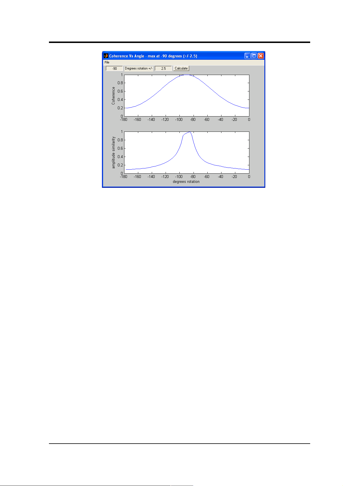
The top window is a graph of
Coherence vs Angle
:
50 Issue C
Page 51
Operator's guide
The two-stage algorithm rotates the N/S and E/W components of
the sensor being tested in small steps.
It measures first the amplitude similarity, and then the
coherence between this new N/S component and the reference
N/S component, for a number of rotation angles.
The error in the final calculation is around 2.5 °.
The peak of the coherence curve (upper graph) therefore
corresponds to the angle of rotation which best matched the
reference component. This angle is shown in the title bar,
together with an estimated error.
You should see a coherence curve which is smooth and
symmetrical. If the curve is distorted, either the surface data is
too noisy or the data selection is too short.
The lower graph shows the overall amplitude similarity of the
rotated signal. This provides an idea of the sign of the coherence
(since signals in perfect antiphase have a high coherence as well
as those in phase). If there are two peaks in the coherence graph,
the correct one is where the amplitude similarity is most
positive.
The sample plots show that the borehole instrument is installed
with its N/S axis at a bearing of –90 ° from true North.
13.The second window shows the result of applying the rotation to
November 2006 51
Page 52
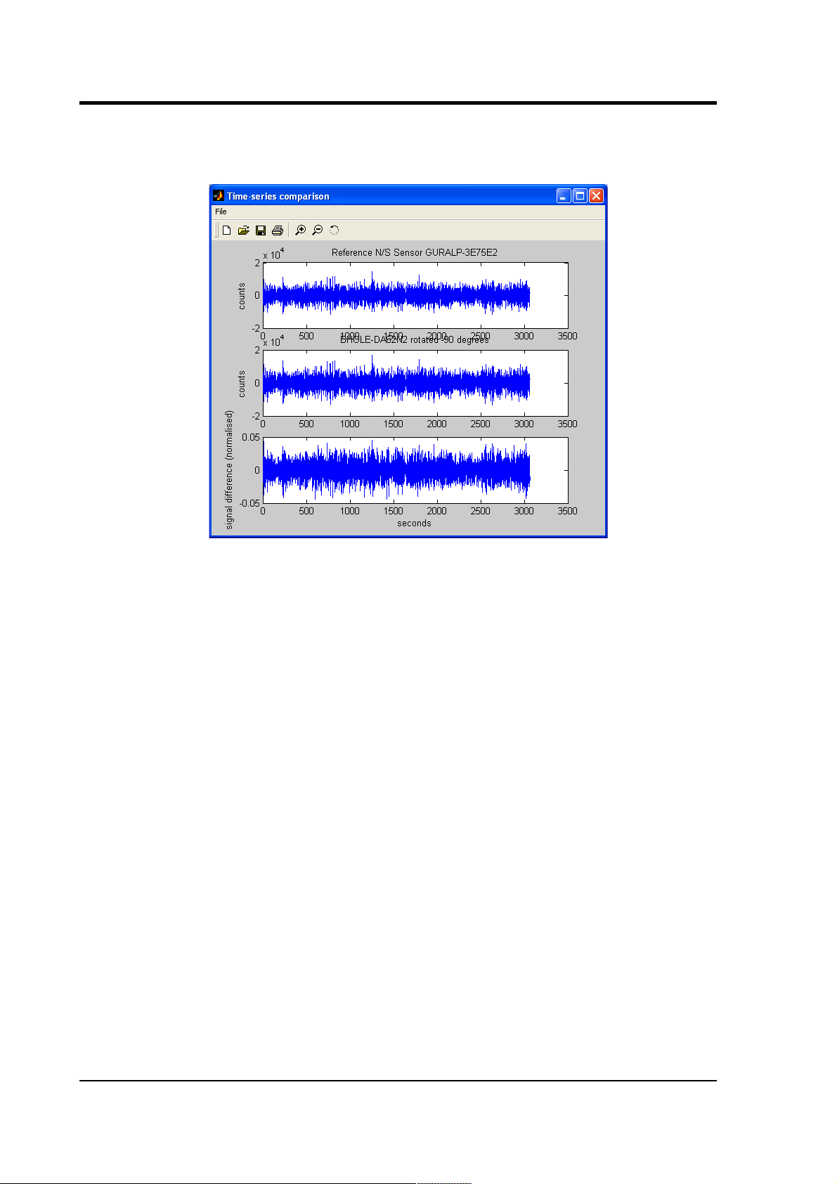
CMG-3TB
the signal,
i.e.
the time series that a sensor in perfect N/S
orientation would have produced:
14.You can perform more accurate calculations by narrowing the
search range. This is done in the two entry boxes on the
Coherence vs Angle
window: the first denotes the centre of the
new search, and the second its range.
The program suggests suitable values for you, so in most cases you can just
click
Calculate
to perform another iteration.
15.A new graph will be displayed showing the results.
52 Issue C
Page 53

Operator's guide
Our sample instrument is thus aligned at –90.35 ± 0.07 °.
16.The error given is only a rough estimate.
You should repeat the orientation experiment several times
using different data sets.
The true error in the computed orientation can be determined
by observing the spread of the results.
The Blacknest orientation method generally provides a reliable
indication of the sensor's orientation. In most cases, the greatest source
of error is in the installation of the reference sensor.
Applying automatic rotation
You can configure a DM24 mk3 digitizer to apply an automatic
rotation to the digitized data and output streams representing ground
motion on true North/South and East/West axes.
This is done within the DSP to minimize the reduction in data quality.
To set up the rotation:
1. Open a terminal session with the digitizer. You can do this with
a program such as minicom (for Linux) or hypertrm (for
Microsoft Windows). Alternatively, you can access the digitizer's
console through Scream! by right-clicking on its icon and
selecting Terminal....
November 2006 53
Page 54

CMG-3TB
You should see an ok prompt, indicating that the digitizer is
ready to receive commands.
2. Type
0 rotation AZIMUTH
where rotation is the angle of deviation from true North that
you measured earlier, as a whole number of tenths of a degree.
This is the same angle (with the same sign) as that given by the
orientation program.
The 0 tells the digitizer to apply the rotation to instrument
number 0 (the first, or only instrument.)
Thus in the example above, you would type 0 -903 AZIMUTH
to make the digitizer rotate signals by –90.3 degrees.
3. Reboot the digitizer with the command re-boot.
4. Collect some more data with the transformation active, and
carry out another orientation calculation. The data from the
downhole instrument should now have a maximum coherence
with the reference sensor at 0 °. Check in particular that the sign
of the rotation you have applied is correct.
54 Issue C
Page 55

Operator's guide
4 Calibrating the 3TB
4.1 The calibration pack
All Güralp sensors are fully calibrated before they leave the factory.
Both absolute and relative calibration calculations are carried out. The
results are given in the calibration pack supplied with each
instrument:
Works Order :
The Güralp factory order number including the
instrument, used internally to file details of the sensor's manufacture.
Serial Number :
The serial number of the instrument
Date :
The date the instrument was tested at the factory.
Tested By :
The name of the testing engineer.
There follows a table showing important calibration information for
each component of the instrument,
VERTICAL, NORTH/SOUTH,
and
EAST/WEST.
Each row details:
Velocity Output (Differential) :
The sensitivity of each component to
velocity at 1 Hz, in volts per m/s. Because the 40TB uses balanced
differential outputs, the signal strength as measured between the +ve
and –ve lines will be twice the true sensitivity of the instrument. To
remind you of this, the sensitivities are given as 2 × (single-ended
sensitivity) in each case.
Mass Position Output :
The sensitivity of the mass position outputs to
acceleration, in volts per m/s². These outputs are single-ended and
referenced to signal ground.
Feedback Coil Constant :
A constant describing the characteristics of
the feedback system. You will need this constant, given in amperes per
m/s², if you want to perform your own calibration calculations (see
below.)
Power Consumption :
The average power consumption of the sensor
during testing, given in amperes and assuming a 12 V supply.
Calibration Resistor :
The value of the resistor in the calibration
circuit. You will need this value if you want to perform your own
calibration calculations (see below.)
November 2006 55
Page 56

CMG-3TB
Poles and zeroes
Most users of seismometers find it convenient to consider the sensor as
a “black box”, which produces an output signal
V
from a measured
input
x.
So long as the relationship between
V
and
x
is known, the
details of the internal mechanics and electronics can be disregarded.
This relationship, given in terms of the Laplace variable s, takes the
form
(
V / x
) (s) =
G × A × H (s
)
In this equation
•
G
is the acceleration output sensitivity (gain constant) of the
instrument. This relates the actual output to the desired input
over the flat portion of the frequency response.
•
A
is a constant which is evaluated so that
A × H (s
) is
dimensionless and has a value of 1 over the flat portion of the
frequency response. In practice, it is possible to design a system
transfer function with a very wide-range flat frequency
response.
The normalising constant A is calculated at a normalising
frequency value fm = 1 Hz, with s = j fm, where j = √–1.
•
H (s
) is the transfer function of the sensor, which can be
expressed in factored form:
In this equation
z
n
are the roots of the numerator polynomial,
giving the zeros of the transfer function, and
p
m
are the roots of
the denominator polynomial giving the poles of the transfer
function.
In the calibration pack, G is the sensitivity given for each component
on the first page, whilst the roots
z
n
and
p
m
, together with the
normalising factor A, are given in the
Poles and Zeros
table. The poles
and zeros given are measured directly at Güralp Systems' factory using
a spectrum analyser. Transfer functions for the vertical and horizontal
sensors may be provided separately.
56 Issue C
Page 57

Operator's guide
Frequency response curves
The frequency response of each component of the 3TB is described in
the normalised amplitude and phase plots provided. The response is
measured at low and high frequencies in two separate experiments.
Each plot marks the low-frequency and high-frequency cutoff values
(also known as –3 dB or half-power points).
If you want to repeat the calibration to obtain more precise values at a
frequency of interest, or to check that a sensor is still functioning
correctly, you can inject calibration signals into the system using a
Güralp digitizer or your own signal generator, and record the
instrument's response.
Obtaining copies of the calibration pack
Our servers keep copies of all calibration data that we send out. In the
event that the calibration information becomes separated from the
instrument, you can obtain all the information using our free e-mail
service. Simply e-mail caldoc@guralp.com with the serial number
of the instrument in the subject line,
e.g.
From: your@email.net
To: caldoc@guralp.com
Subject: T3A15
The server will reply with the calibration documentation in Word
format. The body of your e-mail will be ignored.
November 2006 57
Page 58

CMG-3TB
4.2 Calibration methods
Velocity sensors such as the 3TB are not sensitive to constant DC
levels, either as a result of their design or because of an interposed
high-pass filter. Instead, three common calibration techniques are
used.
• Injecting a step current allows the system response to be
determined in the time domain. The amplitude and phase
response can then be calculated using a Fourier transform.
Because the input signal has predominantly low-frequency
components, this method generally gives poor results. However,
it is simple enough to be performed daily.
• Injecting a sinusoidal current of known amplitude and
frequency allows the system response to be determined at a spot
frequency. However, before the calibration measurement can be
made the system must be allowed to reach a steady state; for low
frequencies, this may take a long time. In addition, several
measurements must be made to determine the response over the
full frequency spectrum.
• Injecting white noise into the calibration coil gives the response
of the whole system, which can be measured using a spectrum
analyser.
You can perform calibration either using a Güralp DM24 digitizer,
which can generate step and sinusoidal calibration signals, or by
feeding your own signals into the instrument through a handheld
control unit.
Before you can calibrate the instrument, its calibration relays need to
be activated by pulling low the
CAL ENABLE
line on the instrument's
connector for the component you wish to calibrate. Once enabled, a
calibration signal provided across the
CAL SIGNAL
and
SIGNAL
GROUND
lines will be routed through the feedback system. You can
then measure the signal's equivalent velocity on the sensor's output
lines. Güralp Handheld Control Units provide a switch for activating
the
CAL ENABLE
line.
4.3 Calibration with Scream!
Güralp digitizers provide calibration signal generators to help you set
up your sensors. Calibration is most easily done through a PC running
Güralp's Scream! software.
58 Issue C
Page 59

Operator's guide
Depending on the digitizer type, sine-wave, step and broadband noise
signal generators may be available. In this section, broadband noise
calibration will be used to determine the complete sensor response in
one action. Please refer to the digitizer's manual for information on
other calibration methods.
1. In Scream!'s main window, right-click on the digitizer's icon and
select Control.... Open the
Calibration
pane.
2. Select the calibration channel corresponding to the instrument,
and choose Broadband Noise. Select the component you wish to
calibrate, together with a suitable duration and amplitude, and
click Inject now. A new data stream, ending Cn (n = 0 – 7) or
MB, should appear in Scream!'s main window containing the
returned calibration signal.
3. Open a Waveview window on the calibration signal and the
returned streams by selecting them and double-clicking. The
streams should display the calibration signal combined with the
November 2006 59
Page 60
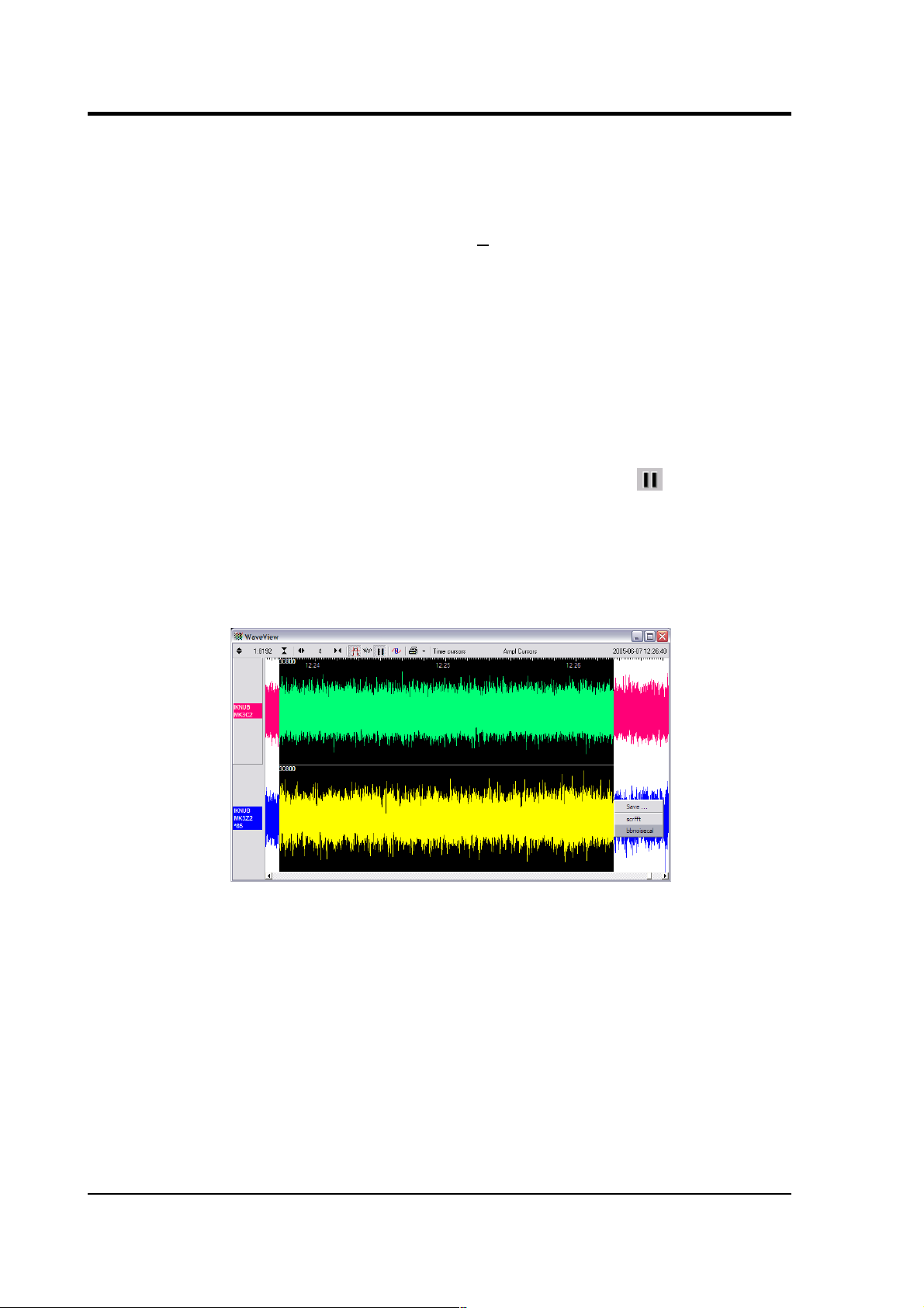
CMG-3TB
sensors' own measurements. If you cannot see the calibration
signal, zoom into the Waveview using the scaling icons at the
top left of the window or the cursor keys.
Drag the calibration stream Cn across the Waveview window, so
that it is at the top.
4. If the returning signal is saturated, retry using a calibration
signal with lower amplitude, until the entire curve is visible in
the Waveview window.
5. If you need to scale one, but not another, of the traces, right-
click on the trace and select Scale.... You can then type in a
suitable scale factor for that trace.
6. Pause the Waveview window by clicking on the icon.
7. Hold down SHIFT and drag across the window to select the
calibration signal and the returning component(s). Release the
mouse button, keeping SHIFT held down. A menu will pop up.
Choose Broadband Noise Calibration.
8. The script will ask you to fill in sensor calibration parameters
for each component you have selected.
60 Issue C
Page 61
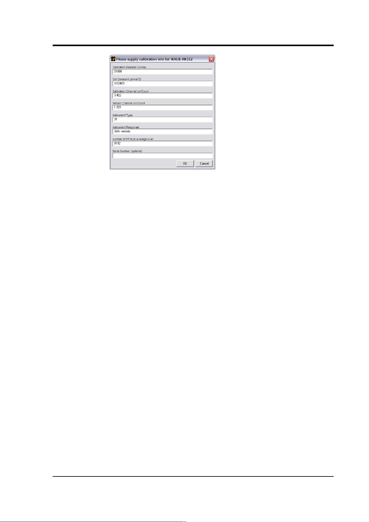
Operator's guide
Most data can be found on the calibration sheet for your sensor.
Under
Instrument response
, you should fill in the sensor
response code for your sensor, according to the table below.
Instrument Type
should be set to the model number of the
sensor.
If the file calvals.txt exists in the same directory as
Scream!'s executable (scream.exe), Scream! will look there for
suitable calibration values. See the Scream! documentation for
more information.
9. Click OK. The script will return with a graph showing the
responsivity of the sensor in terms of amplitude and phase plots
for each component (if appropriate.)
The accuracy of the results depends on the amount of data you
have selected, and its sample rate. To obtain good-quality results
at low frequency, it will save computation time to use data
collected at a lower sample rate; although the same information
is present in higher-rate streams, they also include a large
amount of high-frequency data which may not be relevant to
your purposes.
November 2006 61
Page 62

CMG-3TB
The bbnoisecal script automatically performs appropriate
averaging to reduce the effects of aliasing and cultural noise.
Sensor response codes
Sensor Sensor type code
Units
(V/A)
CMG-3TB, 30 s – 50 Hz response
CMG-3B_30S_50HZ V
CMG-3TB, 100 s – 50 Hz response
CMG-3B_100S_50HZ V
CMG-3TB, 120 s – 50 Hz response
CMG-3B_120S_50HZ V
CMG-3TB, 360 s – 50 Hz response
CMG-3B_360S_50HZ V
CMG-3TB, 360 s – 100 Hz response
CMG-3B_360S_100HZ V
4.4 Calibration with a handheld control unit
If you prefer, you can inject your own calibration signals into the
system through a handheld control unit. The unit includes a switch
which activates the calibration relay in the seismometer, and 4 mm
banana sockets for an external signal source. As above, the equivalent
input velocity for a sinusoidal calibration signal is given by
v = V /
2 π
f R K
where
V
is the peak-to-peak voltage of the calibration signal, f is the
signal frequency, R is the magnitude of the calibration resistor and K is
the feedback coil constant. R and K are both given on the calibration
sheet supplied with the 3TB.
The calibration resistor is placed in series with the transducer.
62 Issue C
Page 63

Operator's guide
Depending on the calibration signal source, and the sensitivity of your
recording equipment, you may need to increase R by adding further
resistors to the circuit.
4.5 The coil constant
The feedback coil constant K is measured at the time of manufacture,
and printed on the calibration sheet. Using this value will give good
results at the time of installation. However, it may change over time.
The coil constant can be determined by tilting the instrument and
measuring its response to gravity. To do this, you will need a mounting
harness for the sonde and apparatus for measuring tilt angles
accurately.
1. Measure the acceleration due to gravity, g, at your location.
2. Tilt the instrument slightly, and measure its attitude and the
gain of the
mass position
output for the component you wish to
calibrate.
3. Repeat this measurement for several tilt angles.
4. For the vertical sensor, the input acceleration is given by
a = g
sin φ, whilst for the horizontal sensor, it is
a = g
( 1 – cos φ ).
Calculate the input acceleration for each of the tilt angles used,
and plot a graph of mass position output against input
acceleration.
5. The gradient of the line obtained gives the sensitivity of the coil
(in V/m/s2, if g was measured in m/s2 and the mass position in
V.)
6. The coil constant
K
is equal to this sensitivity divided by the
value of the displacement feedback resistor, given on the
calibration sheet.
November 2006 63
Page 64

CMG-3TB
5 Inside the 3TB
5.1 The sensors
The horizontal and vertical sensors are similar in design. The inertial
mass in both cases consists of a transducer coil and a leaf-spring
suspended boom which swings on a frictionless hinge. A triangular
spring supports the weight of the mass; in the vertical sensor this
spring is pre-stressed, with a natural period around 0.5 s, whilst the
horizontal sensor has an unstressed flat spring with a natural period
around 1 s. CMG-3TB sensors have no spurious resonances below 140
Hz, and weigh around 180 g. The small boom size and stiff springs
allow three independent instruments to be mounted within the casing,
together with all the associated feedback electronics.
The sensor and hole lock units are stacked one on top of the other with
a set of accurately-machined stacking tubes, which also form part of
the sensor's pressure housing. Fixing holes provided on each end face
allow for simple and accurate assembly. The base of each unit includes
a double “O” ring to isolate the sensor from any pressure variations in
the atmosphere.
The 3TB functions by monitoring the position of each mass with a
capacitative position sensor. The three sensors are identical. Signals
from the sensors are fed into an electronic processing unit, which is
mounted in a screened compartment above the mechanical
components (see below for details on the feedback circuitry.)
When the instrument is being transported, the masses are locked
securely in their frames so as to relieve strain on the support hinges.
This locking is performed by a small motor-driven clamp in response
to a signal from the surface controller unit.
Before using the instrument, the boom of the vertical sensor must be
levelled and the bases of the horizontal sensors tilted, so that the
masses are centred in their equilibrium positions. These adjustments
are made by small DC motors controlled remotely.
See Chapter 3, “Installing the 3TB in a borehole” for detailed
instructions on how to set up your 3TB installation.
64 Issue C
Page 65
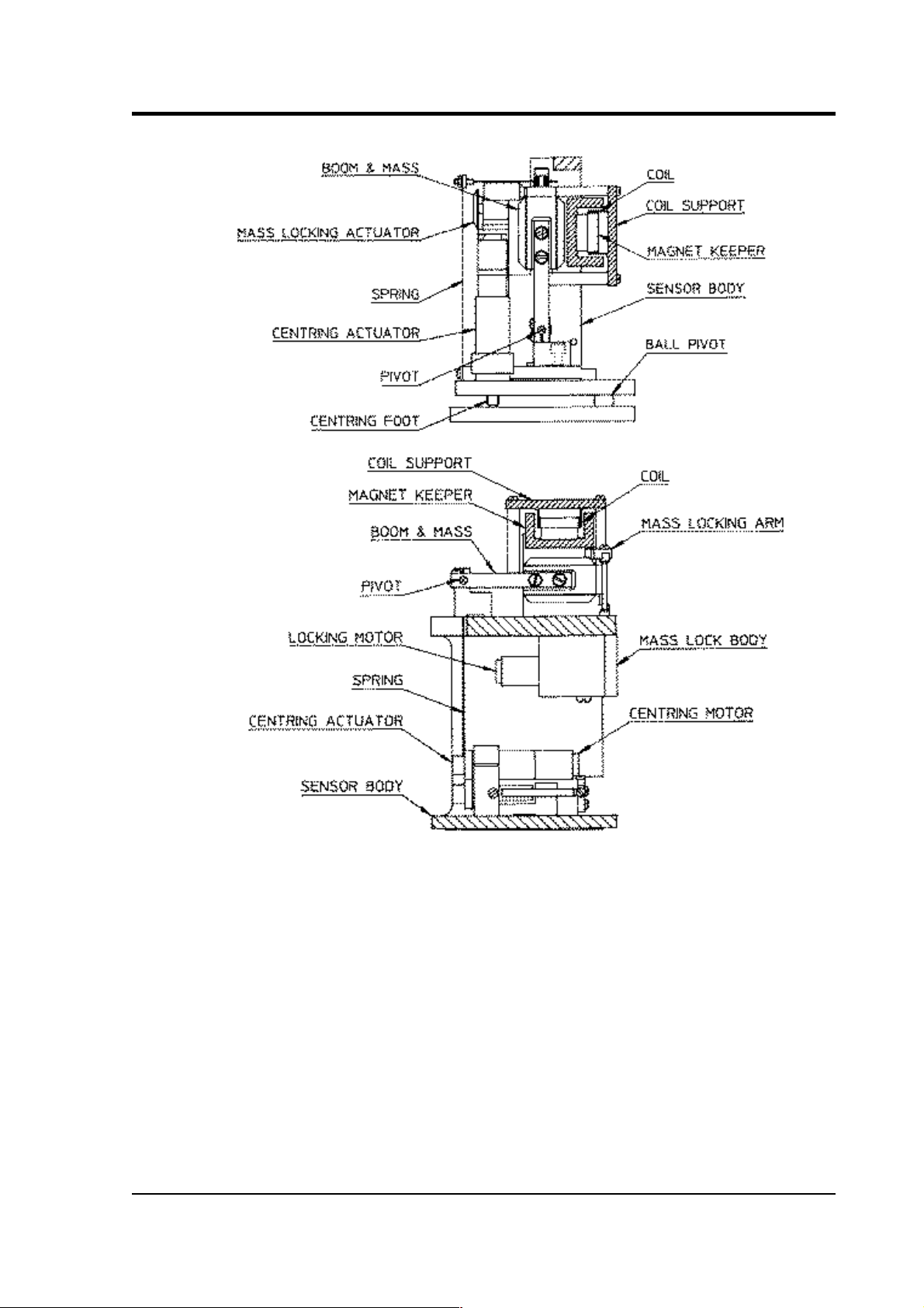
Operator's guide
The signal voltages output by the 3TB are proportional to ground
velocity, and are transmitted from the instrument on balanced
differential lines. In addition, mass position signals are sent as singleended circuits referred to analogue ground on the output plug. The
3TB also receives control signals, which are used to clamp and
unclamp the masses, and to run the motors which level and centre the
instrument once in position. Finally, a line is provided for you to apply
a calibrating voltage to the force transducers, thereby measuring the
deflection sensitivity.
November 2006 65
Page 66

CMG-3TB
5.2 The control system
The internal operations of the 3TB are supervised by a control
microprocessor, which drives the mass clamping and centring
adjustment motors. It responds to commands sent on three input lines
by grounding for 0.2 – 7 seconds.
The signals you can send to the microprocessor are termed
LOCK
,
UNLOCK
, and
CENTRE
. Each command acts on the vertical, N/S and
E/W masses in turn. The microprocessor prevents the system from
attempting incompatible actions (
e.g.
centring when the masses are
clamped.)
While a command is taking place, the
BUSY
LED will flash; you can
use this for diagnostic purposes. See the description of each command
for full details.
When no command is active,
i.e.
all three lines are high, the control
microprocessor goes into a power-saving mode. In routine operation,
the lines are controlled from the breakout box, Handheld Control Unit
or digitizer. If you send control signals to the 3TB manually, you must
ensure that the lines are pulled high after sending the signal, or the
equipment may be damaged. A “biased-OFF” type switch can be used
for this purpose.
LOCK
This command unlocks the masses and clamps the horizontal sensors
by tilting them up to their end stops.
If
LOCK
is activated when the masses are already locked, the processor
will unlock them and attempt to lock again. This is useful if you
suspect that the locking procedure has failed.
In detail, the process acts as shown in the following graph. The top
three streams are the
mass position
outputs of each component (Z, N/S
and E/W, respectively), whilst the bottom one represents the state of
the
BUSY
LED (up = on).
66 Issue C
Page 67

Operator's guide
In the five-stage process, each mass in turn is locked with a motorised
micrometer (stages 1, 2, 4), and the
N/S
and
E/W
sensor bases are tilted
to their end stops (stages 3 and 5). At some point during each tilting
stage, the position of the relevant mass will flip to one or other side.
The
BUSY
LED is lit during each stage, but goes out briefly between
stages, allowing you to follow the progress of the lock.
UNLOCK
This command unlocks the sensor masses and prepares the instrument
to begin operating.
If
UNLOCK
is activated when the masses are already unlocked, the
processor will lock them and attempt to unlock again. This is useful if
you suspect that the locking procedure has failed.
During the
UNLOCK
procedure, the instrument automatically
performs a round of centring for each component.
November 2006 67
Page 68

CMG-3TB
Again, you can use the
BUSY
LED to monitor the progress of
unlocking.
1. The instrument checks to see whether the vertical mass is
locked, and unlocks it if necessary.
2. The vertical mass is centred by applying pulses to the motor.
This stage is often very short, since the vertical mass is locked
near its central position.
3. The instrument checks the N/S sensor and base, and unlocks the
sensor.
4. The N/S sensor base is tilted to its level position. This process
takes rather longer. At some point during this stage, the mass
may flip to the other side (as seen in the green trace.)
5. The N/S sensor mass is centred by applying pulses to the motor.
This stage will take longer than stage 2, since it must move the
mass all the way from its end stop. As the mass nears the centre,
the control circuit spaces out the pulses.
6. The E/W component is checked and unlocked.
7. The E/W sensor base is tilted to its level position as in step 4.
8. The E/W sensor mass is centred as in step 5.
After unlocking, the instrument automatically performs a round of
centring (see below).
68 Issue C
Page 69
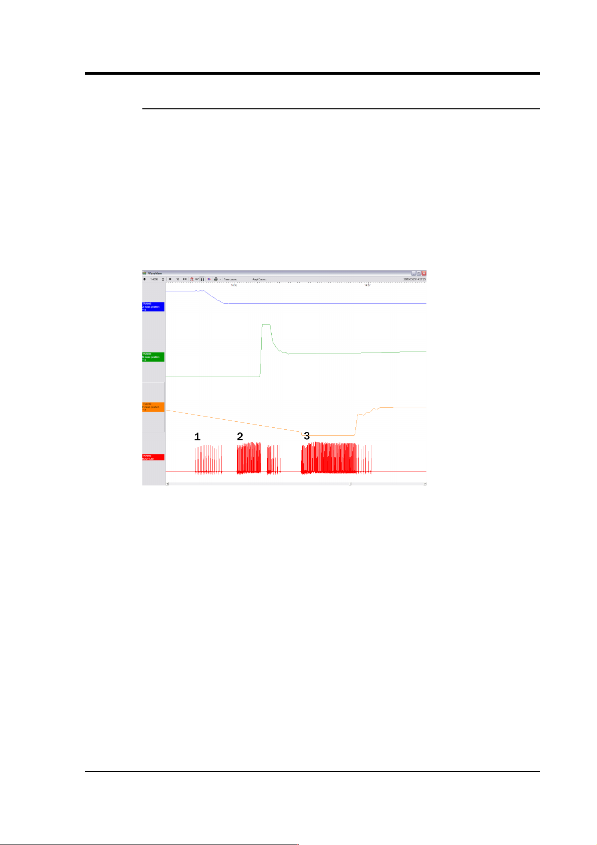
Operator's guide
CENTRE
This command re-centres the masses. If the masses are clamped, or if
the sensor mass positions do not exceed ± 1.2 V, the
CENTRE
command does nothing. Otherwise, it attempts to zero the output of
the vertical, N/S and E/W sensors in sequence by exerting small extra
forces on the boom. For the vertical sensor, a motor-driven adjuster
presses a small spring lever against the boom until the mass position
sensor indicates an offset close to zero. In the case of the horizontal
sensors, the sensor frame is tilted on its base plate. Again, the
controller monitors the mass position sensor and stops the centring
process once it reaches its lowest offset.
This graph shows a typical centring process:
1. The
BUSY
LED pulses to indicate that it is centring the Z
component. Each pulse corresponds to a small force on the
mass. The pulses become more spaced out as this goes on, until
a pulse is missed, signifying that no corrective impulse is
needed.
2. The N/S component follows in the same way. The mass position
output does not change for a while, as the true mass position is
outside the range of the output. In this case, the pulses cause the
mass to overshoot the central position, and a second group of
pulses in the opposite direction is applied to bring it into line.
3. The E/W component follows in the same way. All three masses
are now centred and the process completes.
November 2006 69
Page 70

CMG-3TB
After the sensor unlocks the masses, the first round of centring has to
move the N/S and E/W components all the way from their end stops,
whilst the Z component is often closer to the proper position. Because
of this, the first Z centring operation takes much less time than the
others, and you may not notice it.
After successful centring, the mass position outputs should be in the
range 0.1 – 0.8 V. If the centring process leaves the mass position
outputs above ±1.1 V, you should start another centring cycle by
activating the
CENTRE
command again. You will probably need to
initiate the centring process several times before the masses are
adequately centred.
5.3 The feedback system
The output from a modern broadband seismometer does not depend on
the natural characteristics of the instrument. Instead, the period and
damping of the sensor is completely determined by a feedback loop
which applies a force to the sensor mass opposing any motion. The
force required to
restrain
the movement of the mass can then be used
to measure the inertial force which it exerts as a result of ground
motion.
All CMG-3 series units are based on these general principles. The
capacitative position sensor for each mass produces a voltage
proportional to the displacement of the mass from its equilibrium
position. After amplification, this voltage generates a current in the
force transducer coil which tends to force the mass back toward
equilibrium. The feedback loop has a sufficiently high gain to cancel
the motion of the mass. Since the mass is not moving, the forces acting
on it must be balanced; the feedback voltage then directly measures
the force, and hence the acceleration, which is being applied to the
mass. The feedback loop introduces a phase shift, which must be
carefully controlled if the instrument is to remain stable over its entire
frequency range. This is achieved using compensation components in
the forward and feedback paths.
Force feedback seismometers of this type rely on the assumption that
the force transducer produces a field of constant strength. The
magnetic circuit and magnet/pole assembly in the 3TB are designed so
that the field strength from the feedback transducer is constant over
large deflections and current levels. Tests have shown that the
mechanical suspension system and electronics of a 3TB instrument are
linear to better than 107 dB (source: measurements made at ASL
during evaluation for the USGS National Network.)
70 Issue C
Page 71
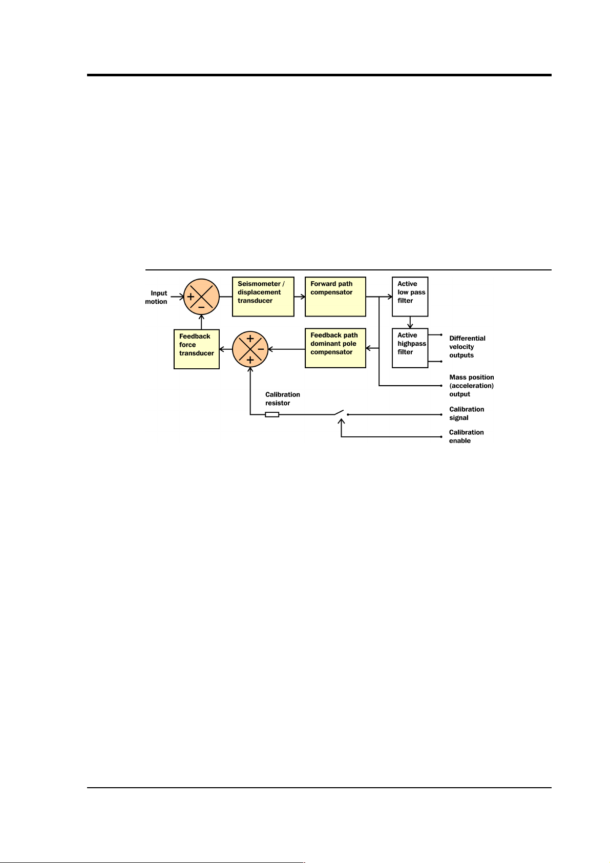
Operator's guide
In a feedback seismometer with a displacement transducer, it is
essential to monitor the acceleration output. This provides the position
of the displacement transducer and therefore also the mass position, as
the displacement transducer is attached to the sensor inertial mass.
The sensor should always be operated with the displacement
transducer centred or nulled, so that the response to input acceleration
is linear.
There are two types of feedback system which can be used in a 3TB
instrument, known as
hybrid
and
conventional-response
feedback.
Hybrid feedback
The
hybrid
feedback circuit contains a single capacitor in parallel with
a resistor, resulting in a single dominant pole at 0.033 Hz (30 s). Below
this frequency, the response of the seismometer is flat to ground
acceleration; above it, the response is flat to velocity. (Other values for
the acceleration-velocity corner can be provided upon request.)
Hybrid-feedback systems provide a stable response, particularly for
portable systems, with a high saturation level at high frequencies and a
high dynamic range at long periods.
An active low-pass filter provides a high-frequency cutoff point at a
frequency you specify. Without the filter, the velocity response is flat
up to 100 Hz. Outside the feedback loop there is an active high-pass
filter with a corner frequency of 0.01 Hz (100 s) or 0.005 Hz (200 s),
which serves to remove any DC offsets.
November 2006 71
Page 72

CMG-3TB
Conventional-response feedback
The
conventional-response
feedback system has an additional parallel
feedback circuit, consisting of a non-inverting integrator in series with
a resistor. This arrangement results in two poles at specified
frequencies. The velocity response of a conventional-response system
is defined by a transfer function identical to that of a conventional
long-period sensor with a damping constant of 0.707 (1/√2) ζ
The seismometer can be supplied with an equivalent resonant
frequency of 0.033 Hz (30 s), 0.01 Hz (100 s) or 0.0083 Hz (120 s) as
required. An active low-pass filter provides a high-frequency cutoff
point at a frequency you specify.
Comparisons
The figures below plot the comparative response of a conventional
velocity output broadband sensor and a hybrid output broadband
sensor. The left-hand graph shows the response in terms of output
against input acceleration in units of V/m/s2, whilst the right-hand
graph is plotted in terms of output against input velocity, in V/m/s.
72 Issue C
Page 73

Operator's guide
November 2006 73
Page 74

CMG-3TB
6 Connector pinouts
This table combines the pinouts for all connectors on the borehole
sensor and breakout box. Control signals are normally active low, but
active high versions can be supplied on request.
Column (a): The single connector on a 3TB sensor, a 32-way mil-spec
waterproof plug (02E-19-32P).
Column (b): The
SENSOR
connector on a breakout box, a 26-way mil-
spec plug (02E-16-26P)
Column (c): The
RECORDER
and
CONTROL
connectors on the
breakout box, both 26-way mil-spec plugs (02E-16-26P).
Column (d): The
POWER
connector on the breakout box, a 10-way mil-
spec socket (02E-12-10S).
(a) (b) (c) (d) Function
A H F Hole lock motor
B b K Hole lock motor return
C Z Z Inclinometer power
D c c B + 12 to 24 V DC power
E b b A 0 V power
F G G Mass position, vertical channel
G J J Mass position, N/S channel
H L L Mass position, E/W channel
J A A Velocity +ve, vertical channel
K B B Velocity –ve, vertical channel
L C C Velocity +ve, N/S channel
M D D Velocity –ve, N/S channel
N E E Velocity +ve, E/W channel
P F F Velocity –ve, E/W channel
R P P Calibration signal (all channels)
S R R Calibration enable (all channels)
T T T Y tilt
U S S X tilt
W K K
BUSY
LED
74 Issue C
Page 75

Operator's guide
V U U Centre
X V V Direct
Z W W Unlock
Y X X Lock
b
Acc/Vel
mode switch*
e N N Signal ground
f Y Y E Control signal ground
j Case ground
*The
Acc/Vel
mode switch pin is used by the automatic centring
process to switch the instrument temporarily into a mode where its
response at normal frequencies is flat to acceleration, and thus in
linear proportion to the mass position. The sensor returns to its
operational mode once the centring process is completed.
November 2006 75
Page 76

CMG-3TB
7 Specifications
Hybrid sensors Velocity output bandwidth 0.1 – 50 Hz
High pass filter output flat
to acceleration
0.01 Hz –
spec
*
High pass filter output flat
to velocity
spec
– 50 Hz*
Mass position output DC – 0.1 Hz
Velocity sensitivity 1400 V/m/s
Acceleration sensitivity
2000 V/m/s
2
Velocity sensors Velocity output bandwidth
spec
– 50 / 100 Hz*
Mass position output DC –
spec
Hz*
Velocity sensitivity 2 × 1000 V/m/s**
Mass position sensitivity
1000 V/m/s
2
Controls Mass locking and unlocking remotely operated
Mass centring
microprocessor
controlled
Mechanics and
electronics
Sensors
3 orthogonal sensors,
each 0.180 kg
Lowest spurious resonance above 140 Hz
Sensor transducer type
capacitive
displacement
Feedback transducer type magnet/coil
Connector
pressure tight,
waterproof
Borehole diameter 89 – 229 mm
Temperature range with
masses locked
–20 to +75 °C
Operational temperature
range
–10 to +65 °C
Power Supply requirements 11 – 36 V DC
Current at 24 V DC 75 mA†
Current at 24 V DC during
centring (average)
115 mA†
Current at 24 V DC during
locking and unlocking
200 mA†
76 Issue C
Page 77

Operator's guide
*spec
refers to the quoted frequency response value,
e.g.
, for a “30 s”
sensor, the value of
spec
would be 30 s = 0.033 Hz.
**Sensors are available with a range of sensitivities between 2 × 750
and 2 × 10,000 V/m/s.
†Because centring, locking, and unlocking consume varying amounts
of power, it is recommended that you use a power supply capable of
delivering 1 A at 12 V.
November 2006 77
Page 78

CMG-3TB
8 Revision history
2006-11-15 C Updated Scream! and SOH; added revision history
2005-05-12 B Original document
78 Issue C
 Loading...