

Page 1

CMG-3T
Triaxial Broadband Seismometer
Ope rat or's g uide
Part No. MAN-030-0001
Designed and manufactured by
Güralp Systems Limited
3 Midas House, Calleva Park
Aldermaston RG7 8EA
England
Proprietary Notice: The information in this manual is
proprietary to Güralp Systems Limited and may not be
copied or distributed outside the approved recipient's
organisation without the approval of Güralp Systems
Limited. Güralp Systems Limited shall not be liable for
technical or editorial errors or omissions made herein,
nor for incidental or consequential damages resulting
from the furnishing, performance, or usage of this
material.
Issue N 2009-07-06
Page 2

CMG-3T
Table of Contents
1 Introduction...............................................................................................................3
1.1 Options................................................................................................................4
2 Installing the 3T........................................................................................................7
2.1 First encounters..................................................................................................7
2.2 Installation notes..............................................................................................10
2.3 Installing in vaults............................................................................................11
2.4 Installing in pits................................................................................................14
2.5 Installing in post-holes....................................................................................18
3 Calibrating the 3T...................................................................................................20
3.1 The calibration pack.........................................................................................20
3.2 Calibration methods.........................................................................................23
3.3 Calibration with Scream! ................................................................................23
3.4 Calibration with a hand-held control unit.......................................................28
3.5 The coil constant..............................................................................................28
4 Accessories...............................................................................................................30
4.1 The breakout box..............................................................................................30
4.2 The hand-held control unit..............................................................................31
4.3 Integrated State-of-Health Controller...............................................................33
5 Inside the 3T............................................................................................................35
5.1 The sensors.......................................................................................................35
5.2 The control system...........................................................................................36
5.3 RS232 control interface....................................................................................41
5.4 The feedback system........................................................................................42
6 Connector pin-outs..................................................................................................47
6.1 Sensor and control unit pin output.................................................................47
6.2 Sensor output (“D”-type connector option).....................................................48
6.3 Sensor output (waterproof connector option).................................................49
6.4 Breakout box POWER connector......................................................................50
7 Specifications..........................................................................................................51
8 Revision history.......................................................................................................53
2 Issue N
Page 3
Operator's guide
1 Introduction
The CMG-3T is a three-axis seismometer consisting of three sensors in
a sealed case, which can measure the north/south, east/west and
vertical components of ground motion simultaneously. Each sensor is
sensitive to ground vibrations in the frequency range 0.003 – 50 Hz, a
broadband frequency response made possible by advanced forcebalance feedback electronics. Because of this wide response range, the
3T can replace many of the instruments conventionally used in a
seismic observatory; it also produces true pulse-shape records suitable
for modern earthquake mechanism analysis.
The 3T is designed for mounting on a hard, near-horizontal surface
well coupled to the bedrock. After levelling and orienting the case, you
can perform accurate adjustments internally by sending the
instrument control signals. These electronics allow it to compensate
for a tilt of up to 3 ° from horizontal.
Once levelled and centred, the 3T will begin operating automatically.
It outputs analogue voltages representing ground velocity on balanced
differential lines. These voltages can be recorded using a separate
logging device or digitizer. For testing and installation purposes, a
hand-held control unit is supplied which can monitor the instrument's
output.
July 2009 3
Page 4

CMG-3T
The seismometer unit is self-contained apart from its 12 Volt power
supply. Centring and mass locking can be carried out by sending
control signals to the instrument, either through the hand-held control
unit or through an attached Güralp digitizer.
Each seismometer is delivered with a detailed calibration sheet
showing its serial number, measured frequency response in both the
long period and the short period sections of the seismic spectrum,
sensor DC calibration levels, and the transfer function in poles/zeros
notation.
1.1 Options
Form factors
The CMG-3T can be supplied in several forms, besides its standard
configuration:
• The CMG-3T Compact is internally identical to the standard 3T,
but has a different arrangement of components allowing it to fit
in a smaller casing.
• The 3T can also be supplied in a slimline form factor, with
vertically-stacked sensors, suitable for installation in post-holes
(see Section 2.5, page 18.).
• The 3T is also available as a fully-fledged borehole instrument,
the CMG-3TB.
Any of these can be supplied with integral digitizers and data
modules, allowing the 3T to form a complete, integrated seismic
installation. For example, the 3TD is a full-height 3T with an
integrated CMG-DM24 digitiser. As an additional option, the 3TD can
be ordered with an Integrated State-of-Health Controller, which
provides the mass-control functions (normally accessed via the breakout box) directly from controls mounted on the instrument. See
section 4.3 on page 33 for more details.
Output types
The standard 3T has a single 26-pin mil-spec waterproof connector for
signals, control and power:
4 Issue N
Page 5
Operator's guide
As an option, the 3T can be supplied with a 26-way “D”-type
connector with standard pin assignments (see section 6.2, page 48.)
Other output connector types may also be supplied, to your own pinout specification.
Sensor control interface
3T instruments can be fitted with an optional RS232 control interface.
The control interface can be used to lock, unlock, and centre the
sensor masses, and query mass positions. See section 5.3, page 41, for
more details.
July 2009 5
Page 6

CMG-3T
Sensor response
The 3T can be supplied with a response which is flat to velocity from
100 Hz to any of 0.1 Hz (10 seconds), 0.033 Hz (30 seconds), 0.016 Hz
(60 seconds), 0.01 Hz (100 seconds), 0.0083 Hz (120 seconds) or 0.0027
Hz (360 seconds). Alternatively, a hybrid response function may be
provided. See Chapter 5 for more details.
If you do not require high-frequency data, a low-pass filter may be
installed at any frequency (below 100 Hz) that you specify.
6 Issue N
Page 7

Operator's guide
2 Installing the 3T
2.1 First encounters
Unpacking
The 3T seismometer is delivered in a single transportation case. The
packaging is specifically designed for the 3T and should be reused
whenever you need to transport the sensor. Please note any damage to
the packaging when you receive the equipment, and unpack on a safe,
clean surface. The package should contain:
• the seismometer;
• a cable to join the sensor to the breakout box;
• the breakout box (which provides separate connections for the
signal, control and power lines);
• a Hand-held Control Unit (HCU) for monitoring sensor outputs
and calibration, if ordered;
• a 10-pin connector for your power lead (see below); and
• a calibration and installation sheet.
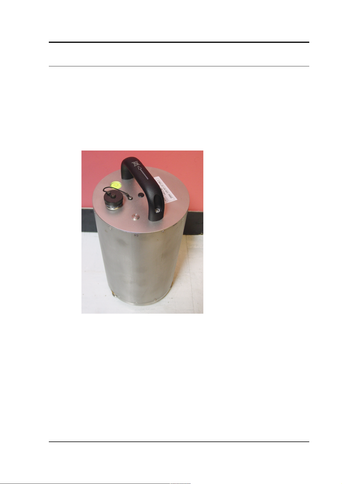
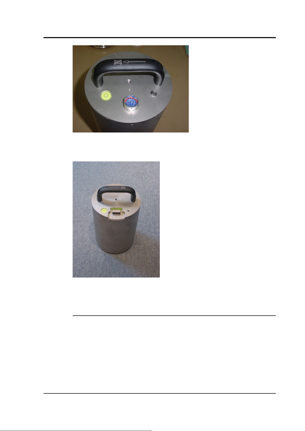
Assuming all the parts are present, stand the seismometer in the centre
of a bench and identify its external features:
• a handle with North indication,
• a multi-pole socket for input and output,
• other optional connectors as ordered;
• a bubble level,
• an air vent port,
• three adjustable feet, and
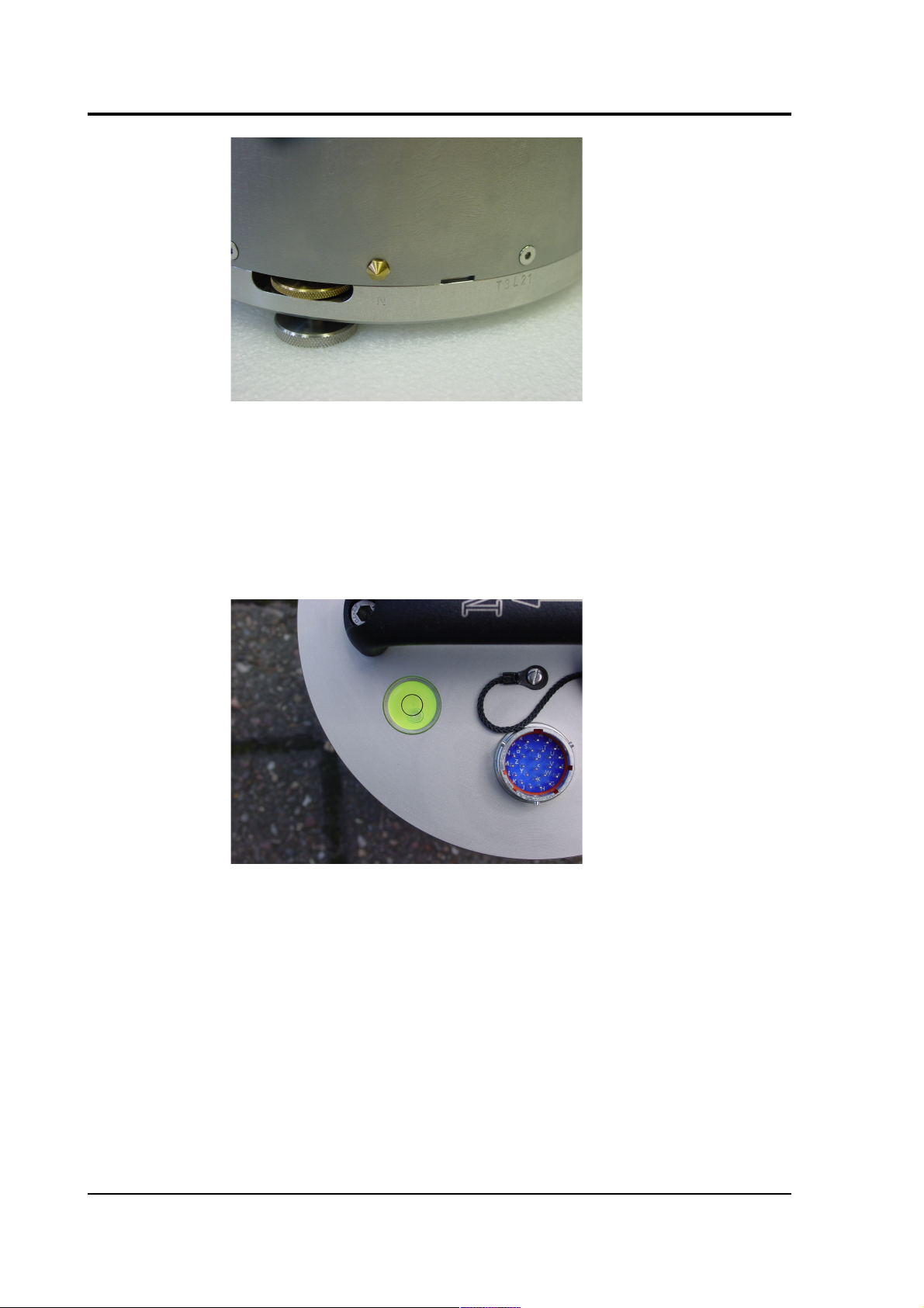
• two accurate orientation pins (one brass and one steel).
July 2009 7
Page 8

CMG-3T
Serial number
The sensor's serial number can be found on the label stuck to the top
lid of the sensor. It is also stamped onto the side of the sensor base,
next to the N/S indicator, and into the lid itself. You should quote this
serial number if you need assistance from Güralp Systems.
Handling notes
The 3T is a sensitive instrument, and is easily damaged if mishandled.
If you are at all unsure about the handling or installation of the device,
you should contact Güralp Systems for assistance.
• Do not bump or jolt any part of the sensor when handling or
unpacking.
• Do not kink or walk on the data cable (especially on rough
surfaces such as gravel), nor allow it to bear the weight of the
sensor.
• Do not connect the instrument to power sources except where
instructed.
• Do not ground any of the signal lines from the sensor.
• Do not move the instrument whilst the masses are unlocked.
You should report any sign of loose components, or any sound
of parts moving inside the instrument, to Güralp Systems.
Connections
The instrument has a single connector, which can be joined using the
cable provided to a digitizer or breakout box. Individually shielded
twisted-pair cabling must be used for the sensor outputs, control lines
and power supply. If you need to make up a suitable cable, you should
confirm the cable type with Güralp Systems.
Using a digitizer
The 3T can be connected directly to any Güralp Systems digitizer
using the signal cable provided. This is the simplest way to use a 3T
instrument. All the instrument's functions are available through the
digitizer, including centring, locking and unlocking.
We recommend that you keep the digitizer near the instrument if at all
possible, to minimize the length of analogue cable required. Once
digitized, the signal is robust to degradation by noise or attenuation.
Keeping the digitizer in the quiet, stable conditions of a seismic
installation also provides it with an optimum environment for the on-
8 Issue N
Page 9

Operator's guide
board ADCs.
Breakout box and hand-held control unit
The 3T can be supplied with an optional robust breakout box, which
provides mass control functions in installations which do not use
compatible digitizers. A hand-held control unit is also available which
can control calibration lines and monitor sensor outputs in addition to
mass control. See chapter 4, page 30, for more details.
Power supply
The sensor requires a 12 Volt power supply, connected via the socket
and breakout box or digitizer. You will need to make up a suitable
cable to connect a 12 V power source to the 10-pin connector on the
breakout box (spare 10-pin mil-spec connectors are provided for this
purpose.) Using a 12 Volt, 25 Ampere-hour, sealed, heavy-duty, leadacid battery, you should expect the instrument to operate for around a
week without recharging.
If you prefer, you can power the 3T directly from the connector on the
top panel (see Chapter 6, page 47.)
A power management module can be installed as an option, which
allows the 3T to operate from a 10 – 15 V supply range. This module
also cuts the input power to the sensor electronics if it drops below
10.5 V, to minimize discharge from battery-operated installations.
Units with serial numbers beginning T33 are provided with a wide
input range DC-DC converter, and can be powered from a 10 – 36 V
supply.
The 3T draws a nominal current of 75 milliamps from a 12 Volt supply
when in use. During locking and unlocking of the sensor masses, this
current rises briefly to 600 milliamps. It is recommended that you
carry a spare 12 Volt battery when visiting an installation for
maintenance, in case the sensor needs to be moved and the on-site
batteries no longer have sufficient charge to perform the locking
procedure.
Signal output
The sensors output voltages representing ground velocity on floating
differential lines. The breakout box provides a RECORDER connector
for attaching to a recording system or digitizer. You can use any multichannel recording system, provided that it has high-impedance
floating differential inputs.
If you are using a Güralp Systems digitizer, you can connect the
instrument directly to the digitizer without using the breakout box;
July 2009 9
Page 10

CMG-3T
power will be supplied through the digitizer, which can also activate
the sensor control lines.
The breakout box also provides a CONTROL output, which can be
connected to the Hand-held Control Unit. This device lets you monitor
output signals from the instrument, and perform on-site calibration.
For more information, see Section 6, page 47.
2.2 Installation notes
The goal of any seismic installation is to ensure that wave-trains
arriving at the instrument accurately reflect the internal motion of
subsurface rock formations. To achieve this, the seismometer and its
emplacement need to be considered as a mechanical system, which
will have its own vibrational modes and resonances. These
frequencies should be raised as high as possible so that they do not
interfere with true ground motion: ideally, beyond the range of the
instrument.
In particular, the sensor needs to be protected against environmental
factors such as
• fluctuations in temperature,
• turbulent air flow around walls or trees, or around sharp
corners or edges in the immediate vicinity of the sensor;
• vibration caused by equipment in or near the installation,
particularly computer equipment; and
• vibration caused by heavy machinery (even at a distance), or by
overhead power lines.
In seismic vaults, instruments are often installed on piers. It is
important to ensure that the interface between the pier and the floor
does not introduce noise, and that the pier itself does not have
resonant frequencies within the passband. Ideally, a seismic pier will
be significantly wider than it is high (to minimize flexing) and will
form a single piece with the floor, e.g. by moulding a poured concrete
floor within a wooden frame.
Many situations do not allow for the construction of a seismic vault.
For example, you may need to deploy quickly to monitor the activity of
a volcano showing signs of rejuvenation, or to study the aftershocks of
a major earthquake. In other cases the site itself may be too remote to
ship in construction equipment.
10 Issue N
Page 11

Operator's guide
Temporary installations can be protected against spurious vibrations
by
• selecting a suitable site,
• placing the instrument in a protective enclosure (an open-sided
box of 5 cm expanded polystyrene slabs, placed over the
instrument and taped down to exclude draughts, makes an
excellent thermal shield),
• standing the sensor on bedrock where possible, or at least deep
in well-compacted subsoil;
• clearing the floor of the hole of all loose material; and
• using as little extra mass as possible in preparing the chamber.
After installation, the instrument case and mounting surface will
slowly return to the local temperature and settle in their positions.
This will take around four hours from the time installation is
completed. If you require long-period recording, you should re-zero
the instrument after this time.
2.3 Installing in vaults
You can install a 3T in an existing seismic vault with the following
procedure:
1. Unpack the sensors from their container, saving the shipping
boxes for later transportation.
2. Prepare the mounting surface, which should be smooth and free
of cracks. Remove any loose particles or dust, and any pieces of
loose surfacing. This ensures good contact between the
instrument's feet and the surface.
3. If it is not already present, inscribe an accurate North-South line
on the mounting surface.
4. Place the sensor over the scribed line, so that the brass and steel
pointers are aligned with the marked directions, with the brass
pointer facing North. This can be done by rotating the base of
the sensor whilst observing it from above. The brass pointer can
be found next to one of the feet.
July 2009 11
Page 12
CMG-3T
If you cannot easily see the pointers, you should align the
sensor using the north arrow on the handle. However, the
alignment of the handle with the sensors inside is less accurate
than the metal pointers, so they should be used wherever
possible.
5. The top panel of the 3T includes a spirit level.
Level the sensor using each of the adjustable feet of the
instrument in turn, until the bubble in the spirit level lies
entirely within the inner circle. (The instrument can operate
with up to 2° of tilt, but with reduced performance.)
The feet are mounted on screw threads. To adjust the height of a
foot, turn the brass locking nut anticlockwise to loosen it, and
rotate the foot so that it screws either in or out. When you are
happy with the height, tighten the brass locking nut clockwise
to secure the foot. When locked, the nut should be at the bottom
of its travel for optimal noise performance.
6. Connect the sensor to a breakout box, or a Güralp digitizer if
12 Issue N
Page 13

Operator's guide
you are using one.
7. Connect a 12 Volt power supply, either directly or through the
breakout box or digitizer.
8. Unlock the sensor. If you have a breakout box or hand-held
control unit, you can do this by holding the ENABLE and
UNLOCK buttons on the unit down together for 7 seconds. The
BUSY LED will start flashing, and then go out.
Alternatively, if you are using a DM24 digitizer and Scream!,
right-click on the digitizer's entry in Scream! and select
Control.... Click on the Mass control tab, followed by Unlock. (If
the Mass control tab is unavailable, check the sensor type in the
Sensor type tab, apply, and open a new Control window.)
Alternatively, if you are using a DM24 digitizer and a DCM,
navigate to the Actions Digitizer Setup Port → → x page for the
digitizer and click on the Unlock instrument button at the
bottom of the page.
After unlocking the masses, you should be careful not to tilt the
instrument or you may damage it.
9. Check the mass position outputs using a digital multimeter,
digitizer or hand-held control unit.
Re-centre the masses if required. If you have a breakout box or
hand-held control unit, you can do this by holding the ENABLE
and CENTRE buttons on the unit down together for 7 seconds.
The BUSY LED will start flashing, and then go out
Alternatively, if you are using a DM24 digitizer and Scream!,
right-click on the digitizer's entry in Scream! and select
Control.... Click on the Mass control tab, followed by Centre.
Alternatively, if you are using a DM24 digitizer and a DCM,
navigate to the Actions Digitizer Setup Port → → x page for the
digitizer and click on the Centre instrument button at the
bottom of the page.
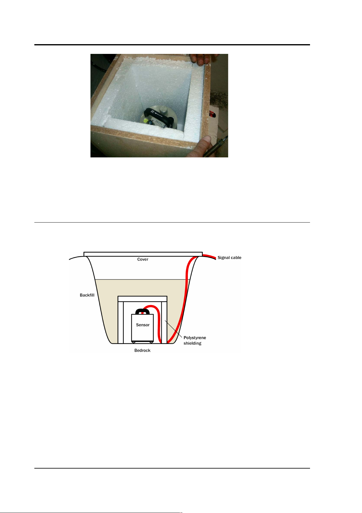
10.Cover the instrument with thermal insulation, for example, a 5
cm expanded polystyrene box. This will shield it from thermal
fluctuations and convection currents in the vault. It also helps
to stratify the air in the seismometer package. Position the
thermal insulation carefully so that it does not touch the sensor
package.
July 2009 13
Page 14
CMG-3T
11.Ensure that the sensor cable is loose and that it exits the
seismometer enclosure at the base of the instrument. This will
prevent vibrations from being inadvertently transmitted along
the cable.
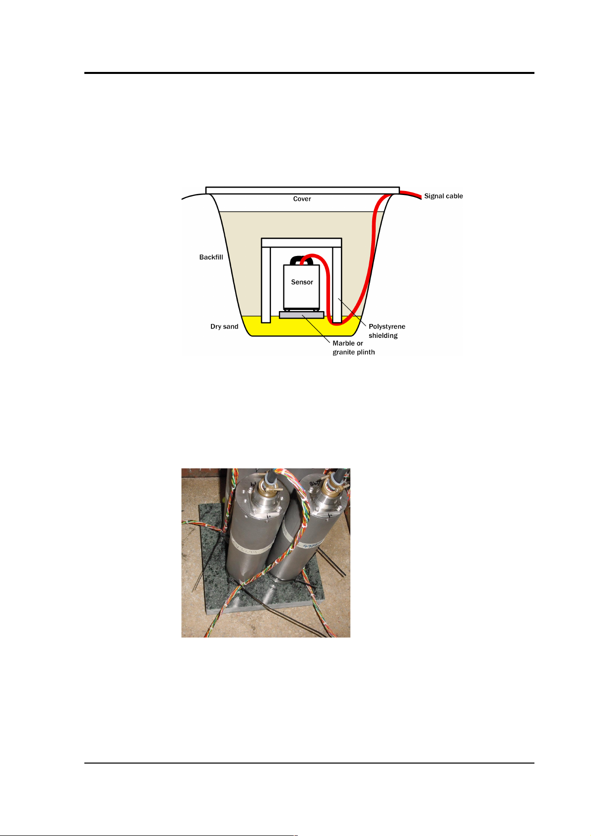
2.4 Installing in pits
For outdoor installations, high-quality results can be obtained by
constructing a seismic pit.
Depending on the time and resources available, this type of
installation can suit all kinds of deployment, from rapid temporary
installations to medium-term telemetered stations.
Ideally, the sensor should rest directly on the bedrock for maximum
coupling to surface movements. However, if bedrock cannot be
reached, good results can be obtained by placing the sensor on a
granite pier on a bed of dry sand.
1. Prepare a hole of 60 – 90 cm depth to compacted subsoil, or
down to the bedrock if possible.
14 Issue N
Page 15
Operator's guide
2. On granite or other hard bedrock, use an angle grinder to plane
off the bedrock at the pit bottom so that it is flat and level.
Stand the instrument directly on the bedrock, and go to step 7.
3. On soft bedrock or subsoil, you should install a pier as depicted
below.
4. Pour a layer of loose, fine sand into the pit to cover the base.
The type of sand used for children's sand-pits is ideal, since the
grains are clean, dry and within a small size range. On top of
the sand, place a smooth, flat granite plinth around 20 cm
across, and shift it to compact the sand and provide a nearlevel surface.
Placing a granite plinth on a sand layer increases the contact
between the ground and the plinth and improves the
performance of the instrument. There is also no need to mix
concrete or to wait for it to set, as in step 5.
5. Alternatively, if time allows and granite is not available,
July 2009 15
Page 16

CMG-3T
prepare a concrete mix with sand and fine grit, and pour it into
the hole. Agitate (“puddle”) it whilst still liquid, to allow it to
flow out and form a level surface, then leave to set. Follow on
from step 7.
Puddled concrete produces a fine-textured, level floor for
situating the seismometer. However, once set hard, the
concrete does not have the best possible coupling to the subsoil
or bedrock, which has some leeway to shift or settle beneath it.
6. Alternatively, for the most rapid installation, place loose soil
over the bottom of the pit, and compact it with a flat stone.
Place the seismometer on top of this stone. This method
emulates that in step 3, but can be performed on-site with no
additional equipment.
7. Set up the instrument as for a vault installation (Section 2.3,
page 11, steps 4 to 9.)
8. The instrument must now be shielded from air currents and
temperature fluctuations. This is best done by covering it with
a thermal shield.
An open-sided box of 5 cm expanded polystyrene slabs is
recommended. If using a seismic plinth on sand (from steps 3–
4 or 5), ensure that the box is firmly placed in the sand,
without touching the plinth at any point. In other installations,
tape the box down to the surface to exclude draughts.
9. Alternatively, if a box is not available, cover the instrument
with fine sand up to the top.
The sand insulates the instrument and protects it from thermal
fluctuations, as well as minimizing unwanted vibration.
10. Ensure that the sensor cable is loose and that it exits the
seismometer enclosure at the base of the instrument. This will
prevent vibrations from being inadvertently transmitted along
the cable.
11. Cover the pit with a wooden lid, and back-fill with fresh turf.
Other installation methods
The recommended installation methods have been extensively tested
in a wide range of situations. However, past practice in seismometer
installation has varied widely.
16 Issue N
Page 17

Operator's guide
Some installations introduce a layer of ceramic tiles between a rock or
concrete plinth and the seismometer (left):
However, noise tests show that this method of installation is
significantly inferior to the same concrete plinth with the tiles
removed (right). Horizontal sensors show shifting due to moisture
trapped between the concrete and tiling, whilst the vertical sensors
show "pings" as the tile settles.
Other installations have been attempted with the instrument encased
in plaster of Paris, or some other hard-setting compound (left):
Again, this method produces inferior bonding to the instrument, and
moisture becomes trapped between the hard surfaces. We recommend
the use of fine dry sand (right) contained in a box if necessary, which
can also insulate the instrument against convection currents and
temperature changes. Sand has the further advantage of being very
easy to install, requiring no preparation.
Finally, many pit installations have a large space around the
seismometer, covered with a wooden roof. Large air-filled cavities are
susceptible to currents which produce lower-frequency vibrations, and
sharp edges and corners can give rise to turbulence. We recommend
that a wooden box is placed around the sensor to protect it from these
currents. Once in the box, the emplacement may be backfilled with
fresh turf to insulate it from vibrations at the surface, or simply roofed
as before.
July 2009 17
Page 18

CMG-3T
By following these guidelines, you will ensure that your seismic
installation is ready to produce the highest quality data.
2.5 Installing in post-holes
The 3T is suitable for installation in post-holes. In soft subsoil, a hole
two to four metres deep and 20cm wide can be conveniently excavated
using a tractor-mounted or hand-operated post-hole auger. To
minimize surface effects, you should ensure that the hole is one metre
deeper than the length of the instrument or, preferably, somewhat
more.
Since the hole has no lining, it may occasionally flood. However, most
soil types are sufficiently permeable to allow water to soak away,
leaving the packing material moist.
A slim-profile 3T instrument is available with vertically stacked
sensors and built-in inclinometer, specifically designed for post-hole
installations. Digitizers or other recording equipment can be placed
either within the hole or in a separate enclosure; alternatively, the
Güralp DM24 is available in modular form, allowing you to attach the
digitizer directly to the instrument.
To install a 3T in a post-hole:
1. Clean the post-hole, making sure there is no loose material
around the mouth of the hole or on its base.
2. Prepare the instrument package, making sure the inclinometer
is visible, and attach it to a winch or hoist by clamping a light
steel cable to the centre of the handle so that the package hangs
vertically. Connect the signal cable to the instrument.
3. Add packing material to the hole to about 15cm depth. Fine
18 Issue N
Page 19

Operator's guide
crushed rock, with a high proportion of rock flour and fine
particles, makes excellent packing material. Alternatively, a
mixture of 3 mm grade angular coarse grit with around 30%
medium grit gives good results. Moisten the packing material
in the hole and ram firm.
4. Lower the instrument to the bottom of the hole, but without
slackening the lifting cable.
5. Fill more packing material around the instrument for about 30
cm, moisten, and ram firm.
6. Use the inclinometer to check that the instrument remains
within its tilt tolerance (± 2°).
7. Continue filling, moistening and packing until the instrument
is buried, checking that the tilt remains within tolerance.
8. Release the strain on the lifting cable, and allow the packing
material to settle for 24 hours.
9. If all is well after the settling period, release the lifting tackle,
coil a tail of the lifting wire into the top of the hole and backfill
almost to the surface.
10. Ensure that the signal cable is slack, and fix it to a support at
the top of the hole.
11. Ram a split wooden bung into the top of the hole, and cover
with sandbags.
12. Attach the signal cable to your recording equipment or
breakout box. Power the sensor, and unlock it. Carry out
preliminary tests using a hand-held control unit, if required.
July 2009 19
Page 20

CMG-3T
3 Calibrating the 3T
3.1 The calibration pack
All Güralp sensors are fully calibrated before they leave the factory.
Both absolute and relative calibration calculations are carried out. The
results are given in the calibration pack supplied with each
instrument:
Works Order : The Güralp factory order number including the
instrument, used internally to file details of the sensor's manufacture.
Serial Number : The serial number of the instrument
Date : The date the instrument was tested at the factory.
Tested By : The name of the testing engineer.
There follows a table showing important calibration information for
each component of the instrument, VERTICAL, NORTH/SOUTH, and
EAST/WEST. Each row details:
Velocity Output (Differential) : The sensitivity of each component to
velocity at 1 Hz, in volts per m/s. Because the 3T uses balanced
differential outputs, the signal strength as measured between the +ve
and –ve lines will be twice the true sensitivity of the instrument. To
remind you of this, the sensitivities are given as 2 × (single-ended
sensitivity) in each case.
Mass Position Output : The sensitivity of the mass position outputs to
acceleration, in volts per m/s². These outputs are single-ended and
referenced to signal ground.
Feedback Coil Constant : A constant describing the characteristics of
the feedback system. You will need this constant, given in amperes per
m/s², if you want to perform your own calibration calculations (see
below.)
Power Consumption : The average power consumption of the sensor
during testing, given in amperes and assuming a 12 V supply.
Calibration Resistor : The value of the resistor in the calibration circuit.
You will need this value if you want to perform your own calibration
calculations (see below.)
20 Issue N
Page 21

Operator's guide
Poles and zeroes
Most users of seismometers find it convenient to consider the sensor
as a “black box”, which produces an output signal V from a measured
input x. So long as the relationship between V and x is known, the
details of the internal mechanics and electronics can be disregarded.
This relationship, given in terms of the Laplace variable s, takes the
form
( V / x ) (s) = G × A × H (s)
In this equation
• G is the acceleration output sensitivity (gain constant) of the
instrument. This relates the actual output to the desired input
over the flat portion of the frequency response.
• A is a constant which is evaluated so that A × H (s) is
dimensionless and has a value of 1 over the flat portion of the
frequency response. In practice, it is possible to design a system
transfer function with a very wide-range flat frequency
response.
The normalising constant A is calculated at a normalising
frequency value fm = 1 Hz, with s = j fm, where j = √–1.
• H (s) is the transfer function of the sensor, which can be
expressed in factored form:
In this equation Zn are the roots of the numerator polynomial,
giving the zeros of the transfer function, and Pm are the roots of
the denominator polynomial giving the poles of the transfer
function.
In the calibration pack, G is the sensitivity given for each component
on the first page, whilst the roots Zn and Pm, together with the
normalising factor A, are given in the Poles and Zeros table. The poles
and zeros given are measured directly at Güralp Systems' factory using
a spectrum analyser. Transfer functions for the vertical and horizontal
sensors may be provided separately.
July 2009 21
Page 22

CMG-3T
Frequency response curves
The frequency response of each component of the 3T is described in
the normalised amplitude and phase plots provided. The response is
measured at low and high frequencies in two separate experiments.
Each plot marks the low-frequency and high-frequency cut-off values
(also known as –3 dB or half-power points).
If you want to repeat the calibration to obtain more precise values at a
frequency of interest, or to check that a sensor is still functioning
correctly, you can inject calibration signals into the system using a
Güralp digitizer or your own signal generator, and record the
instrument's response.
Obtaining copies of the calibration pack
Our servers keep copies of all calibration data that we send out. In the
event that the calibration information becomes separated from the
instrument, you can obtain all the information using our free e-mail
service. Simply e-mail caldoc@guralp.com with the serial number
of the instrument in the subject line, e.g.
From: your@email.net
To: caldoc@guralp.com
Subject: T3A15
The server will reply with the calibration documentation in Word
format. The body of your e-mail will be ignored. If you want data for
several sensors, put their serial numbers together on the subject line,
separated by commas.
22 Issue N
Page 23

Operator's guide
3.2 Calibration methods
Velocity sensors such as the 3T are not sensitive to constant DC levels,
either as a result of their design or because of an interposed high-pass
filter. Instead, three common calibration techniques are used.
• Injecting a step current allows the system response to be
determined in the time domain. The amplitude and phase
response can then be calculated using a Fourier transform.
Because the input signal has predominantly low-frequency
components, this method generally gives poor results. However,
it is simple enough to be performed daily.
• Injecting a sinusoidal current of known amplitude and
frequency allows the system response to be determined at a spot
frequency. However, before the calibration measurement can be
made the system must be allowed to reach a steady state; for low
frequencies, this may take a long time. In addition, several
measurements must be made to determine the response over the
full frequency spectrum.
• Injecting white noise into the calibration coil gives the response
of the whole system, which can be measured using a spectrum
analyser.
You can perform calibration either using a Güralp DM24 digitizer,
which can generate step and sinusoidal calibration signals, or by
feeding your own signals into the instrument through a hand-held
control unit.
Before you can calibrate the instrument, its calibration relays need to
be activated by pulling low the CAL ENABLE line on the instrument's
connector for the component you wish to calibrate. Once enabled, a
calibration signal provided across the CAL SIGNAL and SIGNAL
GROUND lines will be routed through the feedback system. You can
then measure the signal's equivalent velocity on the sensor's output
lines. Güralp Hand-held Control Units provide a switch for activating
the CAL ENABLE line.
3.3 Calibration with Scream!
Güralp digitizers provide calibration signal generators to help you set
up your sensors. Calibration is most easily done through a PC running
Güralp's Scream! software.
Depending on the digitizer type, sine-wave, step and broadband noise
signal generators may be available. In this section, broadband noise
July 2009 23
Page 24

CMG-3T
calibration will be used to determine the complete sensor response in
one action. Please refer to the digitizer's manual for information on
other calibration methods.
1. In Scream!'s main window, right-click on the digitiser's icon and
select Control.... Open the Calibration pane.
2. Select the calibration channel corresponding to the instrument,
and choose Broadband Noise. Select the component you wish
to calibrate, together with a suitable duration and amplitude,
and click Inject now. A new data stream, ending Cn (n = 0 – 7)
or MB, should appear in Scream!'s main window containing the
returned calibration signal.
3. Open a Waveview window on the calibration signal and the
returned streams by selecting them and double-clicking. The
streams should display the calibration signal combined with the
sensors' own measurements. If you cannot see the calibration
signal, zoom into the Waveview using the scaling icons at the
24 Issue N
Page 25

Operator's guide
top left of the window or the cursor keys.
Drag the calibration stream Cn up the Waveview window, so
that it is at the top.
4. If the returning signal is saturated, retry using a calibration
signal with lower amplitude. Repeat until the entire curve is
visible in the Waveview window.
5. If you need to scale one, but not another, of the traces, right-
click on the trace and select Scale.... You can then type in a
suitable scale factor for that trace.
6. Pause the Waveview window by clicking on the icon.
7. Hold down SHIFT and drag across the window to select the
calibration signal and the returning component(s). Release the
mouse button, keeping SHIFT held down. A menu will pop up.
Choose Broadband Noise Calibration. This option runs a script
called bbnoisecal which automatically performs appropriate
averaging to reduce the effects of aliasing and cultural noise.
8. The script will ask you to fill in sensor calibration parameters
for each component you have selected.
July 2009 25
Page 26

CMG-3T
Most data can be found on the calibration sheet for your sensor.
Under Instrument response, you should fill in the sensor
response code for your sensor, according to the table below.
Instrument Type should be set to the model number of the
sensor.
If the file calvals.txt exists in the same directory as
Scream!'s executable (scream.exe), Scream! will look there for
suitable calibration values. A sample calvals.txt is supplied
with Scream!, which you can edit to your requirements. Each
stream has its own section in the file, headed by the line
[instrument-id]. The instrument-id is the string which
identifies the digitizer in the left-hand pane, e.g. GURALP-DEMO.
It is always 6 characters (the system identifier) followed by a
dash, then 4 characters (the serial number.) For example:
[instrument-id]
Serial-Nos=T3X99
VPC=3.153,3.147,3.159
G=1010,1007,1002
COILCONST=0.02575,0.01778,0.01774
CALVPC=3.161
CALRES=51000
TYPE=sensor-type
RESPONSE=response-code
9. Click OK. The script will return with a graph showing the
responsivity of the sensor in terms of amplitude and phase plots
for each component (if appropriate.)
The accuracy of the results depends on the amount of data you
have selected, and its sample rate. To obtain good-quality
results at low frequency, it will save computation time to use
data collected at a lower sample rate; although the same
26 Issue N
Page 27

Operator's guide
information is present in higher-rate streams, they also include
a large amount of high-frequency data which may not be
relevant to your purposes.
The bbnoisecal script automatically performs appropriate
averaging to reduce the effects of aliasing and cultural noise.
Sensor response codes
Sensor Sensor type code
Units
(V/A)
CMG-5T or 5TD, DC – 100 Hz response
CMG-5_100HZ A
CMG-40T-1 or 6T-1, 1s – 50 Hz response
CMG-40_1HZ_50HZ V
CMG-40T-1 or 6T-1,
1s – 100 Hz response
CMG-40_1S_100HZ V
CMG-40T-1 or 6T-1,
2s – 100 Hz response
CMG-40_2S_100HZ V
CMG-40T-1 or 6T-1,
10s – 100 Hz response
CMG-40_10S_100HZ V
CMG-40, 20s – 50 Hz response
CMG-40_20S_50HZ V
CMG-40, 30s – 50 Hz response
CMG-40_30S_50HZ V
CMG-3T or 3ESP, 30s – 50 Hz response
CMG-3_30S_50HZ V
CMG-40, 60s – 50 Hz response
CMG-40_60S_50HZ V
CMG-3T or 3ESP, 60s – 50 Hz response
CMG-3_60S_50HZ V
CMG-3T or 3ESP, 100s – 50 Hz response
CMG-3_100S_50HZ V
CMG-3T or 3ESP, 120s – 50 Hz response
CMG-3_120S_50HZ V
July 2009 27
Page 28

CMG-3T
Sensor Sensor type code
Units
(V/A)
CMG-3T, 360s – 50 Hz response
CMG-3_360S_50HZ V
CMG-3TB or 3V / 3ESP borehole,
30s – 50 Hz response
CMG-3B_30S_50HZ V
CMG-3TB or 3V / 3ESP borehole,
100s – 50 Hz response
CMG-3B_100S_50HZ V
CMG-3TB or 3V / 3ESP borehole,
120s – 50 Hz response
CMG-3B_120S_50HZ V
3.4 Calibration with a hand-held control unit
If you prefer, you can inject your own calibration signals into the
system through a hand-held control unit. The unit includes a switch
which activates the calibration relay in the seismometer and 4 mm
banana sockets for an external signal source. As above, the equivalent
input velocity for a sinusoidal calibration signal is given by
v = V / 2 π f R K
where V is the peak-to-peak voltage of the calibration signal, f is the
signal frequency, R is the value of the calibration resistor and K is the
feedback coil constant. R and K are both given on the calibration sheet
supplied with the 3T.
The calibration resistor is placed in series with the transducer.
Depending on the calibration signal source and the sensitivity of your
recording equipment, you may need to increase R by adding further
resistors to the circuit.
3.5 The coil constant
The feedback coil constant K is measured at the time of manufacture
and printed on the calibration sheet. Using this value will give good
results at the time of installation. However, it may change over time.
The coil constant can be determined by tilting the instrument and
measuring its response to gravity. To do this, you will need apparatus
for measuring tilt angles accurately.
1. Measure the acceleration due to gravity, g, at your location.
2. Tilt the instrument slightly, and measure its attitude and the
gain of the mass position output for the component you wish to
calibrate.
28 Issue N
Page 29

Operator's guide
3. Repeat this measurement for several tilt angles.
4. For the vertical sensor, the input acceleration is given by
a = g sin φ, whilst for the horizontal sensor, it is
a = g ( 1 – cos φ ).
Calculate the input acceleration for each of the tilt angles used,
and plot a graph of mass position output against input
acceleration.
5. The gradient of the line obtained gives the sensitivity of the coil
(in V/m/s², if g was measured in m/s² and the mass position in
V.)
6. The coil constant K is equal to this sensitivity divided by the
value of the displacement feedback resistor, as given on the
calibration sheet.
July 2009 29
Page 30

CMG-3T
4 Accessories
4.1 The breakout box
This unit separates the lines in the signal cable, so you can connect a
power supply, a recording system, and the hand-held control unit:
You can also use the breakout box to centre, lock and unlock the
sensor masses. You will need to provide power through the breakout
box's POWER connector to do this (see below.)
• To unlock the sensor masses, hold down the ENABLE and
UNLOCK buttons simultaneously for 7 seconds. The BUSY LED
will light. All three masses are unlocked, each in turn. The
sensor then automatically moves on to centre the masses, during
which time the BUSY LED will flash. When the BUSY LED goes
out, the instrument is ready for use.
You should not attempt to move the instrument without relocking the masses.
• To lock the sensor masses, hold down the ENABLE and LOCK
buttons simultaneously for 7 seconds. When the BUSY LED goes
30 Issue N
Page 31

Operator's guide
out, the instrument is ready for transportation.
• To re-centre the sensor masses, hold down the ENABLE and
CENTRE buttons simultaneously for 7 seconds. When the BUSY
LED stops flashing, the centring process has finished. You may
need to initiate several rounds of centring before the instrument
is ready; when no more centring is required, pressing the
ENABLE and CENTRE buttons has no effect.
For more details on the control system, see Section 5.2, page 36.
The standard breakout box is rain resistant but not waterproof. If you
intend to use a breakout box in your installation, you should site it
away from potential flooding. If this is not possible, a larger unit is
optionally available which can be immersed in water. (The 3T itself is,
however, completely waterproof.)
4.2 The hand-held control unit
This portable control unit provides
easy access to the seismometer's
control commands, as well as
displaying the output velocity and
mass position (i.e. acceleration) on
an analogue meter. It takes input
from the 26-pin connector at the
bottom, and repeats it at the
connector on the side for
connection to further equipment.
The hand-held control unit can be
sited up to fifty metres from the
breakout box.
The meter
The meter at the top of the unit allows you to monitor the voltage
outputs of the instrument. You can use the knob below to select, for
each of the three components, either the mass position output or the
July 2009 31
Page 32

CMG-3T
velocity output. There is also a RANGE switch allowing you to alter the
sensitivity of the meter.
Calibration
The hand-held control unit can be used to calibrate the 3T. To activate
the calibration relays, turn the knob to the component you wish to
calibrate, and introduce a calibration signal on the CAL SIG banana
sockets.
Control commands
You can use the hand-held control unit to centre, lock and unlock the
sensor masses.
• To unlock the sensor masses, press the ENABLE switch down,
and the LOCK/UNLOCK switch up simultaneously. The BUSY
LED will light. All three masses are unlocked, each in turn. The
sensor then automatically moves on to centre the masses, during
which time the BUSY LED will flash. When the BUSY LED goes
out, the instrument is ready for use.
You should not attempt to move the instrument without relocking the masses.
• To lock the sensor masses, press the ENABLE and
LOCK/UNLOCK switches down simultaneously. When the BUSY
LED goes out, the instrument is ready for transportation.
• To re-centre the sensor masses, press the ENABLE and CENTRE
switches down simultaneously. When the BUSY LED stops
flashing, the centring process has finished. You may need to
initiate several rounds of centring before the instrument is
ready. When no more centring is required, pressing the
ENABLE and CENTRE buttons has no effect.
Note: The ENABLE, LOCK, CENTRE and UNLOCK switches require
only a single quick press to initiate the processes. Do not hold them
down.
For more details on the control system, see Section 5.2, page 36.
Outputs
The remaining banana sockets provide easy access to the output
voltages of the instrument. For each component (vertical, N/S and
E/W):
32 Issue N
Page 33

Operator's guide
• the left-hand two sockets expose the balanced differential
outputs representing ground velocity, and
• the right-hand socket exposes the mass position (acceleration)
output.
Ground references for each of these voltages are provided at the
bottom of the unit. Ensure that you do not connect either side of a
differential output to ground.
4.3 Integrated State-of-Health Controller
The CMG-3TD variant (a CMG-3T with an
integrated DM24 digitiser) is available with an
optional, in-built state-of-health controller.
This option provides a simple means to centre,
lock and unlock the masses without the need for
a hand-held control unit.
The lid of the device is fitted with four
momentary, colour-coded push-buttons, labelled
“ENABLE” (black), “CENTRE” (blue), “UNLOCK”
(green) and “LOCK” (red) - together with a red
LED, labelled “BUSY”.
These buttons are used in a similar manner to
those on the break-out box with the exception
that it is not necessary to hold the buttons down
for seven seconds - one second is adequate.
July 2009 33
Page 34

CMG-3T
• To unlock the sensor masses, hold down the ENABLE and
UNLOCK buttons simultaneously for one second. The BUSY LED
will light. All three masses are unlocked, each in turn. The
sensor then automatically moves on to centre the masses, during
which time the BUSY LED will flash. When the BUSY LED goes
out, the instrument is ready for use.
You should not attempt to move the instrument without relocking the masses.
• To lock the sensor masses, hold down the ENABLE and LOCK
buttons simultaneously for one second. When the BUSY LED
goes out, the instrument is ready for transportation.
• To re-centre the sensor masses, hold down the ENABLE and
CENTRE buttons simultaneously for one second. When the
BUSY LED stops flashing, the centring process has finished. You
may need to initiate several rounds of centring before the
instrument is ready; when no more centring is required,
pressing the ENABLE and CENTRE buttons has no effect.
For more details on the mass control system, see Section 5.2, page 36.
34 Issue N
Page 35

Operator's guide
5 Inside the 3T
5.1 The sensors
The horizontal and vertical sensors are similar in design. The inertial
mass in both cases consists of a transducer coil and a leaf-spring
suspended boom which swings on a frictionless hinge. A triangular
spring supports the weight of the mass; in the vertical sensor this
spring is pre-stressed with a natural period of around 0.5 seconds,
whilst the horizontal sensor has an unstressed flat spring with a
natural period of around 1 second. CMG-3T sensors have no spurious
resonances below 140 Hz, and weigh around 180 g. The small boom
size and stiff springs allow three independent instruments to be
mounted within the casing, together with all the associated feedback
electronics.
The 3T functions by monitoring the position of each mass with a
capacitative position sensor. The three sensors are identical. Signals
from the sensors are fed into an electronic processing unit, which is
mounted in a screened compartment above the mechanical
components (see below for details on the feedback circuitry.)
When the instrument is being transported, the masses are locked
securely in their frames so as to relieve strain on the support hinges.
This locking is performed by a small motor-driven clamp in response
to a signal from the surface controller unit.
Before using the instrument, the boom of the vertical sensor must be
levelled and the bases of the horizontal sensors tilted, so that the
masses are centred in their equilibrium positions. These adjustments
are made by small DC motors controlled remotely.
July 2009 35
Page 36

CMG-3T
The signal voltages output by the 3T are proportional to ground
velocity and are transmitted from the instrument on balanced
differential lines. In addition, mass position signals are sent as singleended circuits referred to analogue ground on the output plug. The 3T
also receives control signals, which are used to clamp and un-clamp
the masses and to run the motors which level and centre the
instrument once in position. Finally, a line is provided for you to
apply a calibrating voltage to the force transducers, thereby measuring
the deflection sensitivity.
5.2 The control system
The internal operations of the 3T are supervised by a control
microprocessor, which drives the mass clamping and centring
36 Issue N
Page 37

Operator's guide
adjustment motors. It responds to commands sent on three input lines
by grounding for 0.2 – 7 seconds.
The signals you can send to the microprocessor are termed LOCK,
UNLOCK, and CENTRE. Each command acts on the vertical, N/S and E/
W masses in turn. The microprocessor prevents the system from
attempting incompatible actions (e.g. centring when the masses are
clamped.)
While a command is taking place, if you are using a Hand-held Control
Unit, its BUSY LED will flash; you can use this for diagnostic purposes.
See the description of each command for full details.
When no command is active, i.e. all three lines are high, the control
microprocessor goes into a power-saving mode. In routine operation,
the lines are controlled from the breakout box, Hand-held Control Unit
or digitizer. If you send control signals to the 3T manually, you must
ensure that the lines are pulled high after sending the signal, or the
equipment may be damaged. A “biased-OFF” type switch can be used
for this purpose.
LOCK
This command locks the masses and clamps the horizontal sensors by
tilting them up to their end stops.
If LOCK is activated when the masses are already locked, the processor
will unlock them and attempt to lock again. This is useful if you
suspect that the locking procedure has failed.
In detail, the process acts as shown in the following graph. The top
three streams are the mass position outputs of each component (Z, N/S
and E/W, respectively), whilst the bottom one represents the state of
the BUSY LED (up = on).
July 2009 37
Page 38

CMG-3T
The five-stage process comprises locking the Z, N/S and E/W masses,
followed by longer periods tilting the N/S and E/W sensor base to their
end stops. During the latter two periods, the position of the N/S and E/
W masses will “flip” to one side.
The BUSY LED is lit during each stage, but goes out briefly between
stages, allowing you to follow the progress of the lock.
UNLOCK
This command unlocks the sensor masses and prepares the instrument
to begin operating.
If UNLOCK is activated when the masses are already unlocked, the
processor will lock them and attempt to unlock again. This is useful if
you suspect that the locking procedure has failed.
38 Issue N
Page 39

Operator's guide
Again, you can use the BUSY LED to monitor the progress of
unlocking.
1. The instrument checks to see whether the Z, N/S and E/W
masses are locked.
2. The instrument checks the N/S and E/W sensor bases.
3. The Z component is unlocked.
4. The N/S and E/W components are unlocked. These are quicker
than the Z component.
5. (see graph below) The N/S sensor base is unlocked, followed by
the E/W base. These processes take longer still.
• After unlocking, the instrument automatically performs a round
of centring (see below).
CENTRE
This command re-centres the masses. If the masses are clamped, or if
the sensor mass positions do not exceed ± 1.2 V, the CENTRE
command does nothing. Otherwise, it attempts to zero the output of
the vertical, N/S and E/W sensors in sequence by exerting small extra
forces on the boom. For the vertical sensor, a motor-driven adjuster
presses a small spring lever against the boom until the mass position
July 2009 39
Page 40

CMG-3T
sensor indicates an offset close to zero. In the case of the horizontal
sensors, the sensor frame is tilted on its base plate. Again, the
controller monitors the mass position sensor and stops the centring
process once it reaches its lowest offset.
This graph shows the entire process of unlocking and centring:
1 – 5. The unlocking process as described above.
6. The BUSY LED pulses to indicate that it is centring the Z
component. The mass position output does not change for a
while, as it is beyond the range of the output. However, after a
few pulses, the position of the Z component comes within range
and is centred. The pulses become more brief as this goes on,
until a pulse is missed (signifying that no corrective impulse is
needed.)
7. The N/S and E/W components follow in the same way, until all
three masses are centred and the process completes. The first
round of centring has to move the N/S and E/W components all
the way from their end stops, whilst the Z component is often
closer to the proper position. Because of this, the first Z centring
operation takes much less time than the others, and you may
not notice it.
After successful centring, the mass position outputs should be in the
range 0.1 – 0.8 V. If the centring process leaves the mass position
outputs above ±1.1 V, you should start another centring cycle by
40 Issue N
Page 41

Operator's guide
activating the CENTRE command again. You will probably need to
initiate the centring process several times before the masses are
adequately centred.
5.3 RS232 control interface
As an option, the 3T can be supplied with an RS232 control interface,
which uses three additional pins on the sensor output connector.
The control electronics save power by switching off the sensor
feedback electronics whilst the masses are locked. When you unlock
the masses, either using the standard logic lines (see above) or over the
RS232 interface, the control electronics automatically “wake up” the
rest of the sensor.
To connect to the RS232 control interface, attach the sensor to a PC's
serial port using the cable supplied, and use a terminal program such
as minicom (on Linux) or HyperTerminal (on Windows) to connect to
the port. Set the baud rate to 4800, with 8 data bits, no parity bit, 0
stop bits and no flow control.
Now power up the sensor. You should see the message PWR OK
indicating that it is ready to receive commands. Each command is a
single character. When you enter a command character, the controller
will echo it back to your terminal so you can see it.
After around 10 s of inactivity, the control electronics will go into
power-saving mode. You will need to wake up the controller by
sending any character before you can issue commands. This character
will not be interpreted as a command, and the controller will not echo
it back to your terminal.
H Help
Sending H causes the controller to reply with a short list of available
commands.
[U]nlock [C]entre [L]ock [S]tatus [Q]uit [H]elp
U Unlock
Sending U will start an unlock sequence, exactly as if you had
activated the Unlock line on the output port. The sensor will
automatically perform one round of centring after it has been
unlocked, and the electronics will be fully activated.
If the unlocking process finishes normally, the controller will reply
July 2009 41
Page 42

CMG-3T
with OK. If there was a problem, such as one or more components
failing to unlock or centre, the controller will report NG (“no good”.)
L Lock
Sending L will start a lock sequence, as if you had activated the Lock
line on the output port (including unlocking the sensor before locking,
if necessary.) The sensor electronics will be placed in power saving
mode as soon as the masses are successfully locked.
If the locking process finishes normally, the controller will reply with
OK. If there was a problem, the controller will report NG.
C Centre
Sending C will start a centring sequence, as if you had activated the
Centre line on the output port. When the process finishes, the
controller will reply with OK, or NG if there was a problem. You may
need to issue the command several times before the masses are
adequately centred.
If you try to centre the masses when they are locked, the controller
will reply with OK immediately but take no action.
S Status
Sending S causes the controller to reply with the current
instantaneous mass positions, e.g.:
V: +5 N: +8 E: -10
The mass positions are measured by the controller's on-board ADC,
which has a nominal range of ±127 counts. For accurate mass position
information, you should use the analogue lines provided elsewhere on
the output connector.
Q Quit
Sending Q ends your command session, and puts the controller into
power-saving mode. To issue further commands, you will need to
wake up the controller by sending any character. This character will
not be treated as a command, and will not be echoed back to your
terminal.
5.4 The feedback system
The output from a modern broadband seismometer does not depend
on the natural characteristics of the instrument. Instead, the period
42 Issue N
Page 43

Operator's guide
and damping of the sensor is completely determined by a feedback
loop which applies a force to the sensor mass opposing any motion.
The force required to restrain the movement of the mass can then be
used to measure the inertial force which it exerts as a result of ground
motion.
All CMG-3 series units are based on these general principles. The
capacitative position sensor for each mass produces a voltage
proportional to the displacement of the mass from its equilibrium
position. After amplification, this voltage generates a current in the
force transducer coil which tends to force the mass back toward
equilibrium. The feedback loop has a sufficiently high gain to cancel
the motion of the mass. Since the mass is not moving, the forces acting
on it must be balanced; the feedback voltage then directly measures
the force, and hence the acceleration, which is being applied to the
mass. The feedback loop introduces a phase shift, which must be
carefully controlled if the instrument is to remain stable over its entire
frequency range. This is achieved using compensation components in
the forward and feedback paths.
Force feedback seismometers of this type rely on the assumption that
the force transducer produces a field of constant strength. The
magnetic circuit and magnet/pole assembly in the 3T are designed so
that the field strength from the feedback transducer is constant over
large deflections and current levels. Tests have shown that the
mechanical suspension system and electronics of a 3T instrument are
linear to better than 107 dB (source: measurements made at ASL
during evaluation for the USGS National Network.)
In a feedback seismometer with a displacement transducer, it is
essential to monitor the acceleration output. This provides the position
of the displacement transducer and therefore also the mass position, as
the displacement transducer is attached to the sensor inertial mass.
The sensor should always be operated with the displacement
transducer centred or nulled, so that the response to input acceleration
is linear.
There are two types of feedback system which can be used in a 3T
instrument, known as hybrid and conventional-response feedback.
These are both described below.
Hybrid feedback
The hybrid feedback method of operation is illustrated by the
following schematic diagram:
July 2009 43
Page 44

CMG-3T
The hybrid feedback circuit contains a single capacitor in parallel with
a resistor, resulting in a single dominant pole. Below this frequency,
which can be varied from the standard 30 seconds, the response of the
seismometer is flat to ground acceleration. Above it, the response is
flat to velocity. Hybrid-feedback systems provide a stable response,
particularly for portable systems, with a high saturation level at high
frequencies and a high dynamic range at long periods.
An active low-pass filter provides a high-frequency cut-off point at a
frequency you specify. Without the filter, the velocity response is flat
up to 100 Hz. Outside the feedback loop there is an active high-pass
filter with a corner frequency of 0.01 Hz (100 s) or 0.005 Hz (200 s),
which serves to remove any DC offsets.
Conventional-response feedback
44 Issue N
Page 45

Operator's guide
The conventional-response feedback system has an additional parallel
feedback circuit, consisting of a non-inverting integrator in series with
a resistor. This arrangement results in two poles at specified
frequencies. The velocity response of a conventional-response system
is defined by a transfer function identical to that of a conventional
long-period sensor with a damping constant of 0.707 (1/√2) ζ
The seismometer can be supplied with an equivalent resonant
frequency of 0.033 Hz (30 seconds), 0.01 Hz (100 seconds) or 0.0083
Hz (120 seconds) as required. An active low-pass filter provides a highfrequency cut-off point at a frequency you specify.
Comparisons
The figures below plot the comparative response of a conventional
velocity output broadband sensor and a hybrid output broadband
sensor. The first graph shows the response in terms of output against
input acceleration in units of V/m/s², whilst the second is plotted in
terms of output against input velocity, in V/m/s.
July 2009 45
Page 46

CMG-3T
46 Issue N
Page 47

Operator's guide
6 Connector pin-outs
6.1 Sensor and control unit pin output
Models with a 26-pin mil-spec plug (02E-16-26P) have the following
pin assignments. The RECORDER and HCU connectors on the breakout
box are connected directly to the SENSOR connector, and therefore
behave identically.
Pin Function
A Velocity +ve, vertical channel
B Velocity –ve, vertical channel
C Velocity +ve, N/S channel
D Velocity –ve, N/S channel
E Velocity +ve, E/W channel
F Velocity –ve, E/W channel
G Mass position, vertical channel
H RS232 ground (RS232 control interface option)
J Mass position, N/S channel
K BUSY LED
L Mass position, E/W channel
M Power –ve (not used in sensors with internal DC-DC converters)
N Signal ground
P Calibration signal (all channels)
R Calibration enable, vertical channel
S Calibration enable, N/S channel
T Calibration enable, E/W channel
U Centre
W Unlock
X Lock
Y Logic ground
Z RS232 transmit from instrument (RS232 control interface option)
a RS232 receive at instrument (RS232 control interface option)
b Power ground
July 2009 47
Page 48

CMG-3T
c Power +ve
In sensors with the RS232 control interface option, the RS232 ground
line (pin H) is isolated from the other ground lines (pins Z and a) using
10 nF decoupling capacitors.
6.2 Sensor output (“D”-type connector option)
As an option, sensors can be equipped with a 26-pin high-density “D”type plug in place of the mil-spec connector.
Pin Function
1 Mass position, N/S component
2 Lock
3 BUSY LED
4 Logic ground
5 Mass position, E/W component
7 RS232 transmit from instrument (RS232 control interface option)
8 Signal ground
9 RS232 receive at instrument (RS232 control interface option)
10 Calibration signal
11 Calibration enable, N/S component
12 Calibration enable, vertical component
13 0 V power
14 Velocity –ve, vertical component
15 Calibration enable, E/W component
16 Velocity +ve, vertical component
17 + 10 – 36 V power
18 Velocity –ve, N/S component
19 Centre
20 Velocity +ve, N/S component
21 Factory use only, do not connect
22 Velocity –ve, E/W component
23 Velocity +ve, E/W component
24 Unlock
25 Mass position, vertical component
48 Issue N
Page 49

Operator's guide
26 RS232 ground (RS232 control interface option)
In sensors with the RS232 control interface option, the RS232 ground
line (pin 26) is isolated from the other ground lines (pins 4 and 8)
using 10 nF decoupling capacitors.
6.3 Sensor output (waterproof connector option)
Waterproofed models have a 32-pin waterproof connector in place of
the 26-pin output connector. These instruments are supplied with an
adapter cable for connecting to a standard digitizer input.
The pin connections are:
Pin Function
1 Mass position, N/S channel
2 Lock
3 BUSY LED
4 Logic ground
5 Mass position, E/W channel
6 Power –ve (not used in sensors with internal DC-DC converters)
7 RS232 transmit from instrument (RS232 control interface option)
8 Signal ground
July 2009 49
Page 50

CMG-3T
9 RS232 receive at instrument (RS232 control interface option)
10 Calibration signal (all channels)
11 Calibration enable, N/S channel
12 Calibration enable, vertical channel
13 Power ground
14 Velocity +ve, vertical channel
15 Calibration enable, E/W channel
16 Velocity –ve, vertical channel
17 Power +ve
18 Velocity +ve, N/S channel
19 Centre
20 Velocity –ve, N/S channel
22 Velocity +ve, E/W channel
23 Velocity –ve, E/W channel
24 Unlock
25 Mass position, vertical channel
26 RS232 ground (RS232 control interface option)
In sensors with the RS232 control interface option, the RS232 ground
line (pin 26) is isolated from the other ground lines (pins 4 and 8)
using 10 nF decoupling capacitors.
6.4 Breakout box POWER connector
This is a standard 10-pin mil-spec plug (02E-12-10P).
Pin Function
A 0 V
B +12 V DC supply
H –12 V DC supply
50 Issue N
Page 51

Operator's guide
7 Specifications
Hybrid sensors Velocity output bandwidth 0.1 – 50 Hz
High pass filter output flat
to acceleration
0.01 Hz – spec*
High pass filter output flat
to velocity
spec – 50 Hz*
Mass position output DC – 0.1 Hz
Velocity sensitivity 1400 V/m/s
Acceleration sensitivity 2000 V/m/s²
Velocity sensors Velocity output bandwidth spec – 50 Hz*
Mass position output DC – spec Hz*
Velocity sensitivity 2 × 750 V/m/s
Mass position sensitivity 1000 V/m/s²
Controls
Mass locking and
unlocking
remotely operated
Mass centring
automatic,
microprocessor
controlled
Mechanics and
electronics
Sensors
3 orthogonal sensors,
each 0.180 kg
Lowest spurious resonance above 140 Hz
Total weight 13.5 kg
Sensor transducer type
capacitive
displacement
Feedback transducer type magnet/coil
Connector pressure tight
Temperature range with
masses locked
–35 to +75 °C
Operational temperature
range
–20 to +65 °C**
Power Supply 10 – 36 V
Current at 12 V DC 75 mA†
Current at 12 V DC during
calibration
100 mA†
Current at 12 V DC during 330 mA†
July 2009 51
Page 52

CMG-3T
centring (average)
Current at 12 V DC during
locking and unlocking
490 mA†
*spec refers to the quoted frequency response value, e.g., for a “30 s”
sensor, the value of spec would be 30 s = 0.033 Hz.
**Temperatures below –20 °C may be accommodated with additional
care. Please consult Güralp Systems for advice.
†Because centring, locking, and unlocking consume varying amounts
of power, it is recommended that you use a power supply capable of
delivering 1 A at 12 V.
52 Issue N
Page 53

Operator's guide
8 Revision history
2009-07-06 N Added integrated SOH controller
2006-10-19 M Added waterproof connector pin-out
2006-08-14 L Added RS232 command interface
2006-06-06 K Moved BB to “Accessories”
2006-02-20 J Corrections; added revision history
2004-10-29 H New document
July 2009 53
 Loading...