

Page 1

CMG-3ESPCD
Digital Broadband Seismometer
Technical Manual
Document No. MAN-C3E-0002
Designed and manufactured by
Güralp Systems Limited
3 Midas House, Calleva Park
Aldermaston RG7 8EA
England
Proprietary Notice: The information in this document is
proprietary to Güralp Systems Limited and may be copied or
distributed for educational and academic purposes but may
not be used commercially without permission.
Whilst every effort is made to ensure the accuracy,
completeness or usefulness of the information in the
document, neither Güralp Systems Limited nor any employee
assumes responsibility or is liable for any incidental or
consequential damages resulting from the use of this
document.
Issue B November 2013
Page 2

CMG-3ESPCD Digital Broadband Seismometer Contents
Table of Contents
1 Preliminary Notes............................................................................................................. 5
1.1 Proprietary Notice......................................................................................................5
1.2 Warnings, Cautions and Notes.................................................................................. 5
1.3 Manuals and Software...............................................................................................5
1.4 Conventions................................................................................................................ 5
2 Introduction....................................................................................................................... 6
2.1 Sensor response.......................................................................................................... 7
3 Installing the 3ESPCD....................................................................................................... 8
3.1 First encounters.......................................................................................................... 8
3.1.1 Unpacking........................................................................................................... 8
3.1.2 Serial number...................................................................................................... 8
3.1.3 Handling notes.................................................................................................... 8
3.1.4 Connections........................................................................................................9
3.1.5 FireWire............................................................................................................... 9
3.1.6 Power supply.....................................................................................................10
3.2 Installation notes...................................................................................................... 10
3.3 Installing in vaults................................................................................................... 11
3.4 Installing in pits....................................................................................................... 14
3.5 Other installation methods...................................................................................... 16
3.6 Rapid installation.....................................................................................................18
3.6.1 Deployment.......................................................................................................18
3.6.2 Recovery............................................................................................................ 21
3.7 Installing in post-holes.............................................................................................22
3.8 Using the 3ESPCD....................................................................................................23
3.8.1 Retrieving data.................................................................................................. 23
3.8.2 Reading digitiser disks......................................................................................24
4 Calibrating the 3ESPCD.................................................................................................. 28
4.1 The calibration pack................................................................................................ 28
4.1.1 Poles and zeroes................................................................................................28
4.1.2 Frequency response curves...............................................................................29
4.1.3 Obtaining copies of the calibration pack.........................................................32
4.2 Calibration methods.................................................................................................32
4.3 Calibration with Scream!.........................................................................................33
4.3.1 Sensor response codes .....................................................................................37
4.4 The coil constant...................................................................................................... 37
5 Using Scream!................................................................................................................. 39
MAN-C3E-0002 Issue B - November 2013
Page 3

CMG-3ESPCD Digital Broadband Seismometer
5.1 Configuring digitisers...............................................................................................39
5.1.1 System ID..........................................................................................................40
5.1.2 Output control...................................................................................................41
5.1.3 Triggering.......................................................................................................... 44
5.1.4 Mux Channels...................................................................................................51
5.1.5 Ports................................................................................................................... 51
5.2 Controlling digitisers................................................................................................ 53
5.2.1 System............................................................................................................... 53
5.2.2 Triggering.......................................................................................................... 54
5.2.3 Calibration......................................................................................................... 54
5.2.4 Mass Control.....................................................................................................54
5.2.5 Data flow........................................................................................................... 55
6 Command line interface................................................................................................. 60
6.1 Introduction.............................................................................................................. 60
6.1.1 FORTH............................................................................................................... 60
6.2 General configuration..............................................................................................61
6.2.1 SET-ID............................................................................................................... 61
6.2.2 SENSOR-TYPE..................................................................................................61
6.2.3 GPS-TYPE.......................................................................................................... 61
6.2.4 BAUD.................................................................................................................62
6.2.5 AZIMUTH......................................................................................................... 62
6.2.6 CROSS............................................................................................................... 63
6.3 Output configuration...............................................................................................63
6.3.1 SAMPLES/SEC..................................................................................................63
6.3.2 CONTINUOUS.................................................................................................. 64
6.3.3 SET-TAPS.......................................................................................................... 64
6.4 Triggering................................................................................................................. 65
6.4.1 TRIGGERS......................................................................................................... 65
6.4.2 TRIGGERED...................................................................................................... 65
6.4.3 STA.................................................................................................................... 65
6.4.4 LTA....................................................................................................................66
6.4.5 RATIOS.............................................................................................................66
6.4.6 PRE-TRIG.......................................................................................................... 66
6.4.7 POST-TRIG........................................................................................................66
6.4.8 TRIGGERIN....................................................................................................... 67
6.4.9 TRIGGEROUT................................................................................................... 67
6.5 Calibration................................................................................................................ 67
6.5.1 SINEWAVE........................................................................................................67
6.5.2 SQUAREWAVE.................................................................................................68
6.5.3 RANDOMCAL...................................................................................................68
6.5.4 MINUTE............................................................................................................69
6.5.5 %AMPLITUDE.................................................................................................. 70
6.6 Actions...................................................................................................................... 70
6.6.1 LOCK................................................................................................................. 70
6.6.2 UNLOCK............................................................................................................ 70
MAN-C3E-0002 3 Issue B - November 2013
Page 4

CMG-3ESPCD Digital Broadband Seismometer
6.6.3 CENTRE.............................................................................................................70
6.6.4 RE-BOOT........................................................................................................... 71
6.7 Data storage and recovery........................................................................................71
6.7.1 SHOW-FLASH.................................................................................................. 71
6.7.2 DIRECT.............................................................................................................. 72
6.7.3 FILING............................................................................................................... 72
6.7.4 ADAPTIVE........................................................................................................ 72
6.7.5 FIFO...................................................................................................................72
6.7.6 DOWNLOAD..................................................................................................... 73
6.7.7 ALL-FLASH....................................................................................................... 73
6.7.8 ALL-DATA......................................................................................................... 73
6.7.9 STREAM............................................................................................................ 73
6.7.10 STATUS-ONLY...............................................................................................74
6.7.11 S/S.................................................................................................................... 74
6.7.12 ALL-TIMES.....................................................................................................74
6.7.13 FROM-TIME.................................................................................................... 74
6.7.14 TO-TIME......................................................................................................... 74
6.7.15 GO.................................................................................................................... 75
6.7.16 END-DOWNLOAD.......................................................................................... 75
6.7.17 DISKMENU..................................................................................................... 75
6.7.18 MBTRANSFER................................................................................................76
6.7.19 ERASEFILE...................................................................................................... 76
7 Inside the 3ESPCD.......................................................................................................... 77
7.1 Inside the 3ESPCD................................................................................................... 77
7.1.1 The sensors.......................................................................................................77
7.1.2 The control system............................................................................................ 77
7.1.3 The feedback system.........................................................................................81
7.2 Inside the DM24.......................................................................................................85
7.2.1 Architecture...................................................................................................... 85
7.2.2 Updating firmware with an EAM.....................................................................87
7.2.3 Updating firmware with Scream!.....................................................................87
8 Appendix A - Connector pin-outs................................................................................... 90
8.1 GPS port.................................................................................................................... 90
8.2 DATA OUT port....................................................................................................... 91
8.3 FIREWIRE port.........................................................................................................92
8.4 AUXILIARY port (optional).....................................................................................93
9 Appendix B - Sensor Specifications............................................................................... 94
10 Appendix C - Digitiser specifications..........................................................................95
11 Revision History............................................................................................................ 97
MAN-C3E-0002 4 Issue B - November 2013
Page 5
CMG-3ESPCD Digital Broadband Seismometer Preliminary Notes
1 Preliminary Notes
1.1 Proprietary Notice
The information in this document is proprietary to Güralp Systems Limited
and may be copied or distributed for educational and academic purposes but
may not be used commercially without permission.
Whilst every effort is made to ensure the accuracy, completeness and
usefulness of the information in the document, neither Güralp Systems
Limited nor any employee assumes responsibility or is liable for any
incidental or consequential damages resulting from the use of this document.
1.2 Warnings, Cautions and Notes
Warnings, cautions and notes are displayed and defined as follows:
1.3 Manuals and Software
All manuals and software referred to in this document are available from the
Güralp Systems website: www.guralp.com unless otherwise stated.
1.4 Conventions
Throughout this manual, examples are given of command-line interactions.
In these examples, a fixed-width typeface will be used:
Example of the fixed-width typeface used.
Commands that you are required to type will be shown in bold:
Example of the fixed-width, bold typeface.
Where data that you type may vary depending on your individual
configuration, such as parameters to commands, these data are additionally
shown in italics:
Example of the fixed-width, bold, italic typeface.
Putting these together into a single example:
System prompt: user input with variable parameters
MAN-C3E-0002 5 Issue B - November 2013
Caution: A yellow triangle indicates a chance of damage to or
failure of the equipment if the caution is not heeded.
Note: A blue circle indicates indicates a procedural or advisory
note.
Page 6
CMG-3ESPCD Digital Broadband Seismometer Introduction
2 Introduction
The CMG-3ESPCD is a full-featured three-axis digital seismometer consisting
of three sensors in an ultra-lightweight case, which can measure the
north/south, east/west and vertical components of ground motion
simultaneously, and a built-in DM24 digitiser.
Each sensor is sensitive to ground vibrations in the frequency range 0.003 Hz
to 50 Hz, a broadband frequency response made possible by advanced
force-balance feedback electronics. Because of this wide response range, the
3ESPCD can replace many of the instruments conventionally used in a
seismic observatory; it also produces true pulse-shape records suitable for
modern earthquake mechanism analysis. Its small size and low weight make
it an ideal choice for rapid deployment of low-noise installations.
The 3ESPCD will produce the best results if it is mounted on a hard,
near-horizontal surface well coupled to the bedrock. After levelling and
orienting the case, you can perform accurate adjustments internally by
sending the instrument control signals. These electronics allow it to
compensate for a tilt of up to 3° from horizontal.
The seismometer unit is self-contained apart from its 12 V power supply.
Once levelled and centred, it will begin operating automatically. Its output is
digitised within the sensor by the internal DM24 digitiser, which provides
data streams in GCF format. The instrument can be connected to a PC's serial
MAN-C3E-0002 6 Issue B - November 2013
Page 7

CMG-3ESPCD Digital Broadband Seismometer Introduction
port or to a Güralp Systems data module using the cable supplied. The
digitiser also controls the instrument's centring and mass locking processes.
Each seismometer is delivered with a detailed calibration sheet showing its
serial number, measured frequency response in both the long period and the
short period sections of the seismic spectrum, sensor DC calibration levels,
and the transfer function in poles/zeros notation.
2.1 Sensor response
The 3ESPCD can be supplied with a response which is flat to velocity from
100 Hz to any of 0.1 Hz (10 s), 0.033 Hz (30 s), 0.016 Hz (60 s), 0.01 Hz (100 s)
or 0.0083 Hz (120 s). Alternatively, a hybrid response function may be
provided. See section 7.1.1 on page 77 for more details.
If you do not require high-frequency data, a low-pass filter may be installed at
a frequency (below 100 Hz) that you specify.
MAN-C3E-0002 7 Issue B - November 2013
Page 8

CMG-3ESPCD Digital Broadband Seismometer Installing the 3ESPCD
3 Installing the 3ESPCD
3.1 First encounters
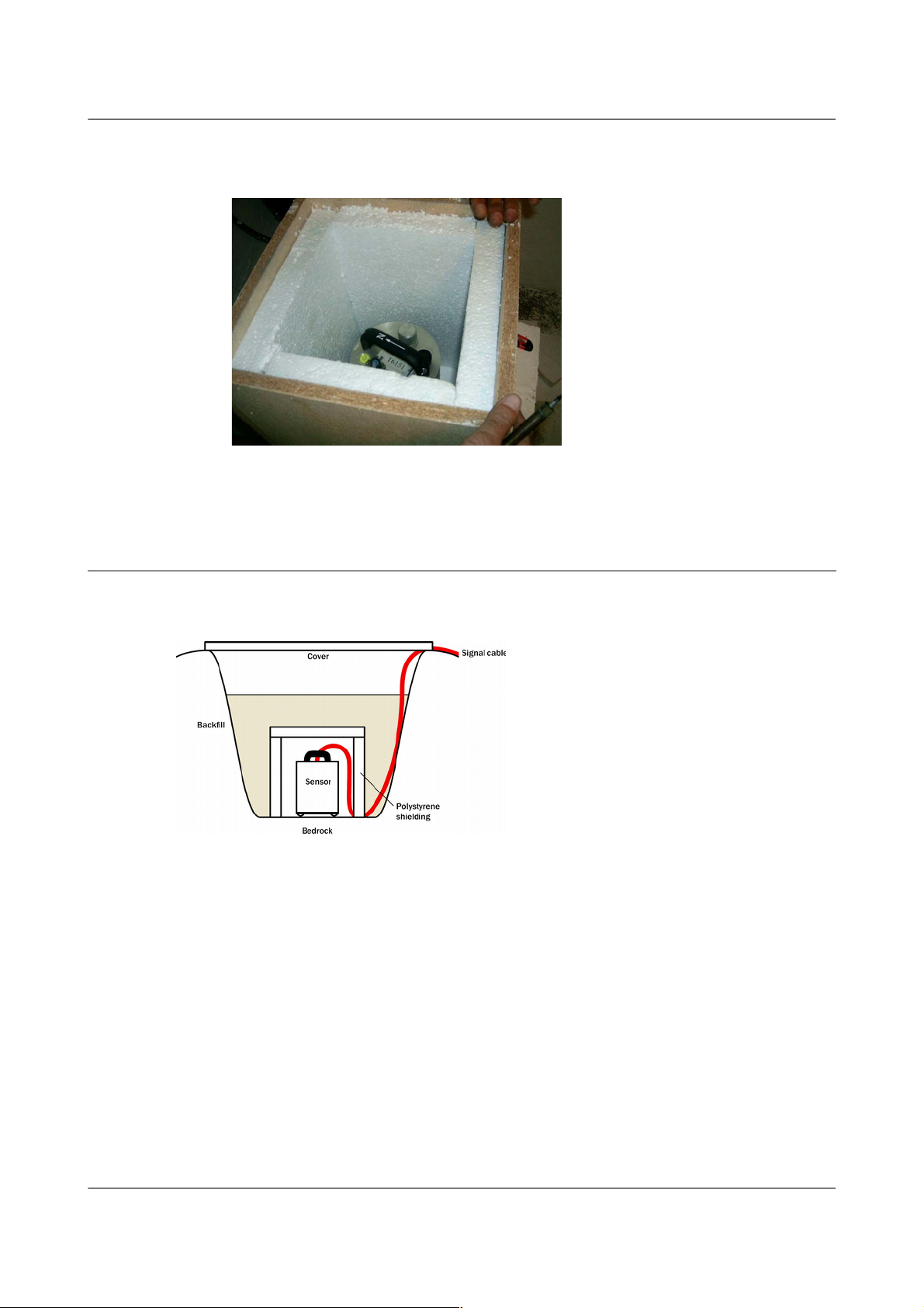
3.1.1 Unpacking
The 3ESPCD seismometer is delivered in a single transportation case. The
packaging is specifically designed for the 3ESPCD and should be reused
whenever you need to transport the sensor. Please note any damage to the
packaging when you receive the equipment, and unpack on a safe, clean
surface. The package should contain:
• the seismometer;
• a GPS unit, if ordered, with cable;
• a 10-pin connector for your power/data lead (see below); and
• a calibration and installation sheet.
Assuming all the parts are present, stand the seismometer in the centre of a
bench and identify its external features:
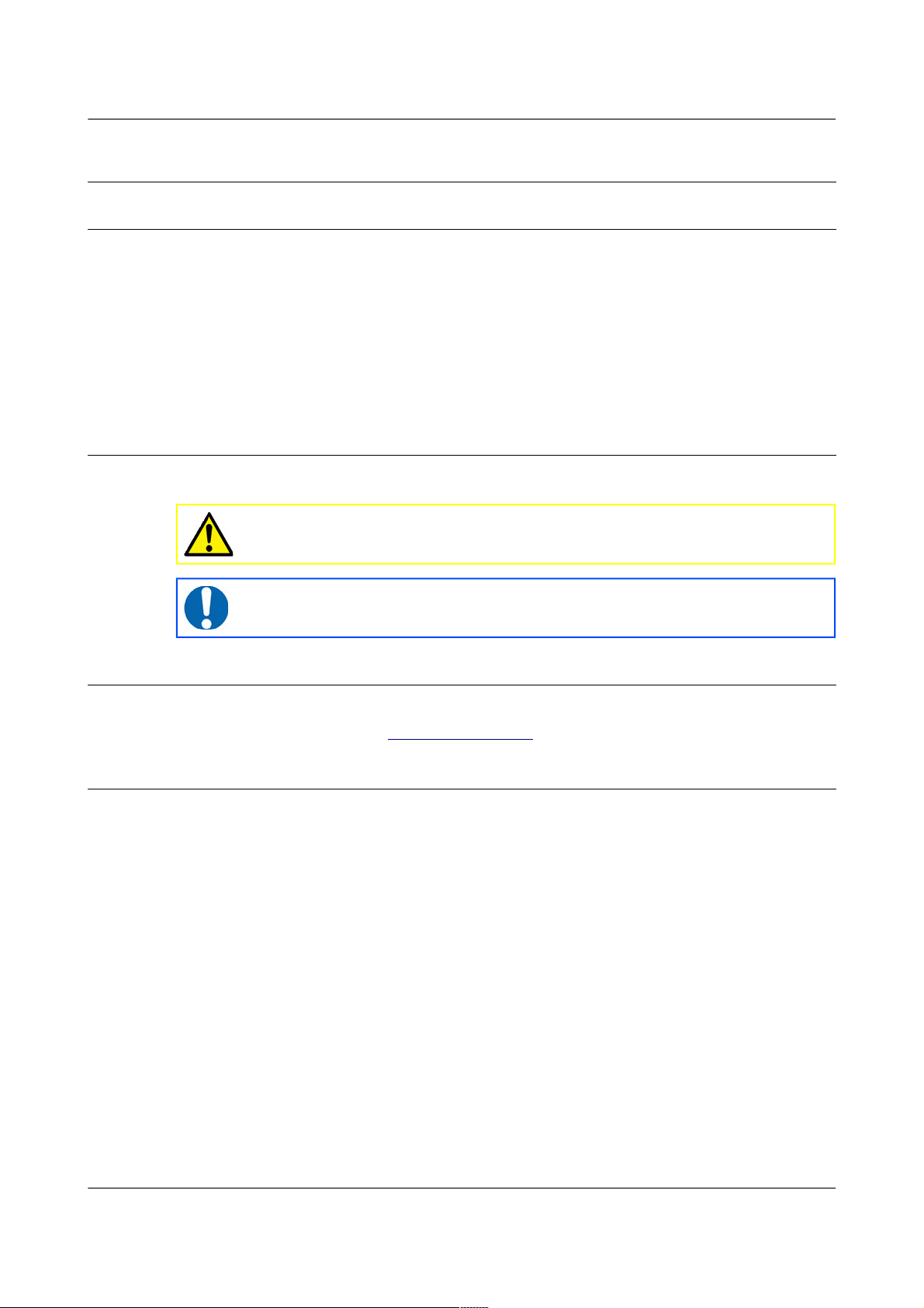
• a handle with North indication,
• DATA OUT and GPS connectors;
• a mil-spec FireWire connector;
• other optional connectors as ordered;
• a bubble level,
• an air vent port,
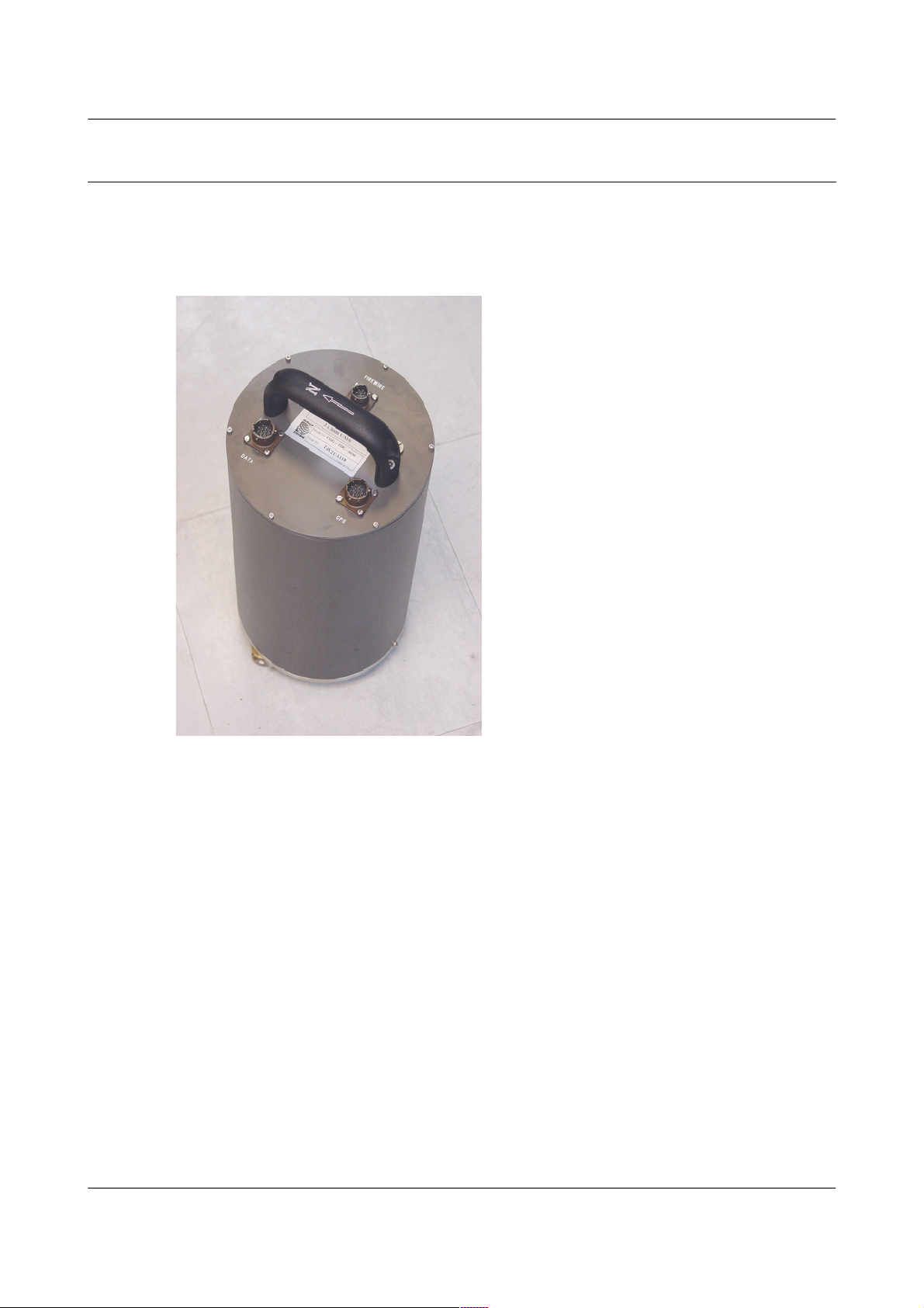
• two adjustable feet, and
• two accurate orientation pins (one brass and one steel).
3.1.2 Serial number
The sensor's serial number can be found on the label stuck to the top lid of the
sensor. You should quote this serial number if you need assistance from
Güralp Systems.
3.1.3 Handling notes
The 3ESPCD is a sensitive instrument, and is easily damaged if mishandled.
If you are at all unsure about the handling or installation of the device, you
should contact Güralp Systems for assistance.
• Avoid bumping or jolting any part of the sensor when handling or
unpacking.
MAN-C3E-0002 8 Issue B - November 2013
Page 9

CMG-3ESPCD Digital Broadband Seismometer Installing the 3ESPCD
• Do not kink or walk on the data cable (especially on rough surfaces
such as gravel), nor allow it to bear the weight of the sensor.
• Do not connect the instrument to power sources except where
instructed.
• Do not ground any of the signal lines from the sensor.
• Avoid moving the instrument whilst the masses are unlocked. The
3ESPCD is designed to tolerate a certain amount of motion with the
sensor masses unlocked, e.g. over short distances carried by hand. For
example, if the remote locking procedure fails, removing the
instrument for diagnostics is unlikely to damage it. However, you
should always lock the sensor masses before shipping or transporting
the sensor over longer distances.
3.1.4 Connections
The instrument has the following connectors:
• The DATA OUT connector outputs RS232 data to your PC or data
module, and also provides power to the instrument.
• The GPS connector is intended for connection to a Güralp GPS module.
• The FIREWIRE connector can be attached to any IEEE.1394 (FireWire)
hard disk or data storage unit using the cable provided.
3.1.5 FireWire
The digitiser has an IEEE.1394 (“FireWire”) port, which you can use to
download data onto a compatible hard disk.
Before you can use the disk, you will need to erase/format it. The digitiser
saves data on the hard disk in raw mode, so you cannot use a PC's standard
software to reset the disk.
To erase/format a FireWire disk for use with the digitiser:
1. Power up the digitiser, and connect it to your computer's serial port.
2. Open its terminal console. To do this using Güralp Systems' Scream!
software, right-click on the digitiser's icon (once it appears) and select
Terminal.... From a Güralp EAM, issue the command
data-terminal
and select the appropriate data source from the menu
3. Issue the command DISKMENU. You will see the message
Plug in FireWire cable
4. Plug in your disk. The digitiser will display information about the disk
as soon as it is detected.
MAN-C3E-0002 9 Issue B - November 2013
Page 10

CMG-3ESPCD Digital Broadband Seismometer Installing the 3ESPCD
5. Within the next seven seconds, press any key to bring up the disk menu.
6. Key to reset the disk.
7. When the reset is complete, remove the disk.
You will now be able to download data onto the disk when required.
3.1.6 Power supply
The sensor requires a 12 V power supply, which it obtains through the DATA
OUT port. You may wish to terminate the supplied power cable in order to
connect a 12 V power source to this connector: it is supplied with bare ends.
Using a 12 V, 25 Ah sealed heavy-duty lead-acid battery, you should expect
the instrument to operate for around a week without recharging.
A power management module can be installed as an option, which allows the
3ESPCD to operate from a 10 – 15 V supply range. This module also cuts the
input power to the sensor electronics if it drops below 10.5 V, to minimize
discharge from battery-operated installations.
The 3ESPCD draws a nominal current of 200 mA from a 12 V supply when in
use. During locking and unlocking of the sensor masses, this current rises
briefly to 750 mA. It is recommended that you carry a spare 12 V battery
when visiting an installation for maintenance, in case the sensor needs to be
moved and the on-site batteries no longer have sufficient charge to perform
the locking procedure.
3.2 Installation notes
The goal of any seismic installation is to ensure that wave-trains arriving at
the instrument accurately reflect the internal motion of subsurface rock
formations. To achieve this, the seismometer and its emplacement need to be
considered as a mechanical system, which will have its own vibrational
modes and resonances. These frequencies should be raised as high as
possible so that they do not interfere with true ground motion: ideally, beyond
the range of the instrument.
In particular, the sensor needs to be protected against environmental factors
such as
• fluctuations in temperature,
• turbulent air flow around walls or trees, or around sharp corners or
edges in the immediate vicinity of the sensor;
• vibration caused by equipment in or near the installation, particularly
computer equipment; and
• vibration caused by heavy machinery (even at a distance), or by
overhead power lines.
MAN-C3E-0002 10 Issue B - November 2013
Page 11

CMG-3ESPCD Digital Broadband Seismometer Installing the 3ESPCD
In seismic vaults, instruments are often installed on piers. It is important to
ensure that the interface between the pier and the floor does not introduce
noise, and that the pier itself does not have resonant frequencies within the
passband. Ideally, a seismic pier will be significantly wider than it is high (to
minimize flexing) and will form a single piece with the floor, e.g. by moulding
a poured concrete floor with a wooden frame.
Many situations do not allow for the construction of a seismic vault. For
example, you may need to deploy quickly to monitor the activity of a volcano
showing signs of rejuvenation, or to study the aftershocks of a major
earthquake; or the site itself may be too remote to ship in construction
equipment.
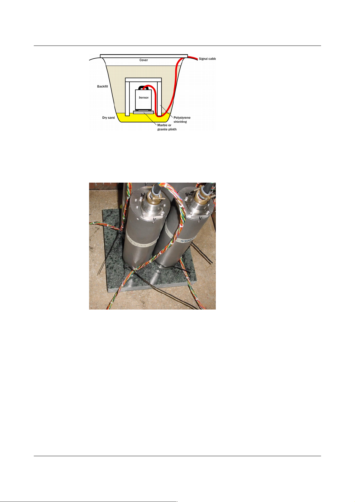
Temporary installations can be protected against spurious vibrations by
• selecting a suitable site,
• placing the instrument in a protective enclosure (an open-sided box of
5 cm expanded polystyrene slabs, placed over the instrument and taped
down to exclude draughts, makes an excellent thermal shield),
• standing the sensor on bedrock where possible, or at least deep in
well-compacted subsoil;
• clearing the floor of the hole of all loose material; and
• using as little extra mass as possible in preparing the chamber.
After installation, the instrument case and mounting surface will slowly
return to the local temperature, and settle in their positions. This will take
around four hours from the time installation is completed. If you require
long-period recording, you should re-zero the instrument after this time.
3.3 Installing in vaults
You can install a 3ESPCD in an existing seismic vault with the following
procedure:
1. Unpack the sensor from its container, saving the shipping box for later
transportation.
2. Prepare the mounting surface, which should be smooth and free of
cracks. Remove any loose particles or dust, and any pieces of loose
surfacing. This ensures good contact between the instrument's feet and
the surface.
3. If it is not already present, inscribe an accurate North-South line on the
mounting surface.
4. Place the sensor over the scribed line, so that the brass and steel
pointers are aligned with the marked directions, with the brass pointer
MAN-C3E-0002 11 Issue B - November 2013
Page 12
CMG-3ESPCD Digital Broadband Seismometer Installing the 3ESPCD
facing North. This can be done by rotating the base of the sensor whilst
observing it from above. The brass pointer can be found next to one of
the feet.
If you cannot easily see the pointers, you should align the sensor using
the north arrow on the handle. However, the alignment of the handle
with the sensors inside is less accurate than the metal pointers, so they
should be used wherever possible.
5. The top panel of the 3ESPCD includes a spirit level.
Level the sensor using each of the adjustable feet of the instrument in
turn, until the bubble in the spirit level lies entirely within the inner
circle. (The instrument can operate with up to 2° of tilt, but with
reduced performance.)
The feet are mounted on screw threads. To adjust the height of a foot,
turn the brass locking nut anticlockwise to loosen it, and rotate the foot
so that it screws either in or out. When you are happy with the height,
tighten the brass locking nut clockwise to secure the foot. When
locked, the nut should be at the bottom of its travel for optimal noise
performance.
MAN-C3E-0002 12 Issue B - November 2013
Page 13
CMG-3ESPCD Digital Broadband Seismometer Installing the 3ESPCD
6. Plug the grey/blue power/data cable into the ten-pin connector on the
instrument's lid and connect a 12 V power supply to the ends of the
grey cable. Connect the DE9 connector to a PC running scream, using a
USB-to-RS232 converter, if required.
Alternatively, connect the ten-pin connector on the instrument's lid to a
CMG-EAM using cable CAS-DCM-0001 (green).
7. Plug in the GPS cable and connect the GPS receiver.
8. In Scream's set-up dialogue, select the “COM Ports” tab and set the
Baud rate of the appropriate COM port to 38,400 Baud. Click OK and
wait for the instrument to appear in Scream's source tree.
Right-click on the digitiser's entry in the source tree and select
Control.... Click on the Mass control tab, followed by Unlock. (If the
Mass control tab is unavailable, check the sensor type in the Sensor
type tab, apply, and open a new Control window.)
Alternatively, if you are using an EAM, navigate to the Control →
Instruments Port X Instrument... page and click on the Unlock→
instrument button.
9. Right-click on the digitiser's entry in Scream's source tree and select
Control.... Click on the Mass control tab, followed by Centre.
Alternatively, if you are using an EAM, navigate to the Control →
Instruments Port X Instrument... page and click on the centre button.→
Monitor the mass positions during the centring operation. You may
need to initiate several rounds of centring before the mass positions
reach an acceptable value.
10. Cover the instrument with thermal insulation, for example, a 5 cm
expanded polystyrene box. This will shield it from thermal
fluctuations and convection currents in the vault. It also helps to
MAN-C3E-0002 13 Issue B - November 2013
Note: GSL strongly recommend USB/RS232 convertors
based on the FTDI chipset. Numerous problems have been
found with convertors based on the other common chip-set.
Caution: After this point, you should be careful not to tilt
the instrument or you may damage it.
Page 14
CMG-3ESPCD Digital Broadband Seismometer Installing the 3ESPCD
stratify the air in the seismometer package. Position the thermal
insulation carefully so that it does not touch the sensor package.
11. Ensure that the cables are loose and that they exit the seismometer
enclosure at the base of the instrument. This will prevent vibrations
from being inadvertently transmitted along the cables.
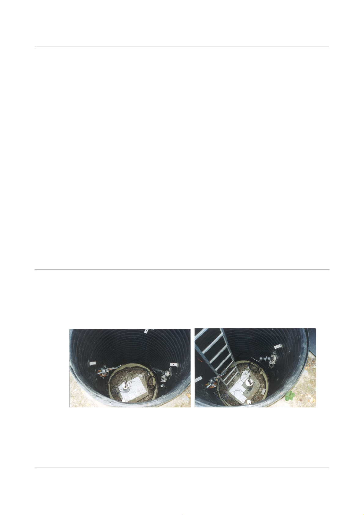
3.4 Installing in pits
For outdoor installations, high-quality results can be obtained by constructing
a seismic pit.
Depending on the time and resources available, this type of installation can
suit all kinds of deployment, from rapid temporary installations to
medium-term telemetered stations.
Ideally, the sensor should rest directly on the bedrock for maximum coupling
to surface movements. However, if bedrock cannot be reached, good results
can be obtained by placing the sensor on a granite pier on a bed of dry sand.
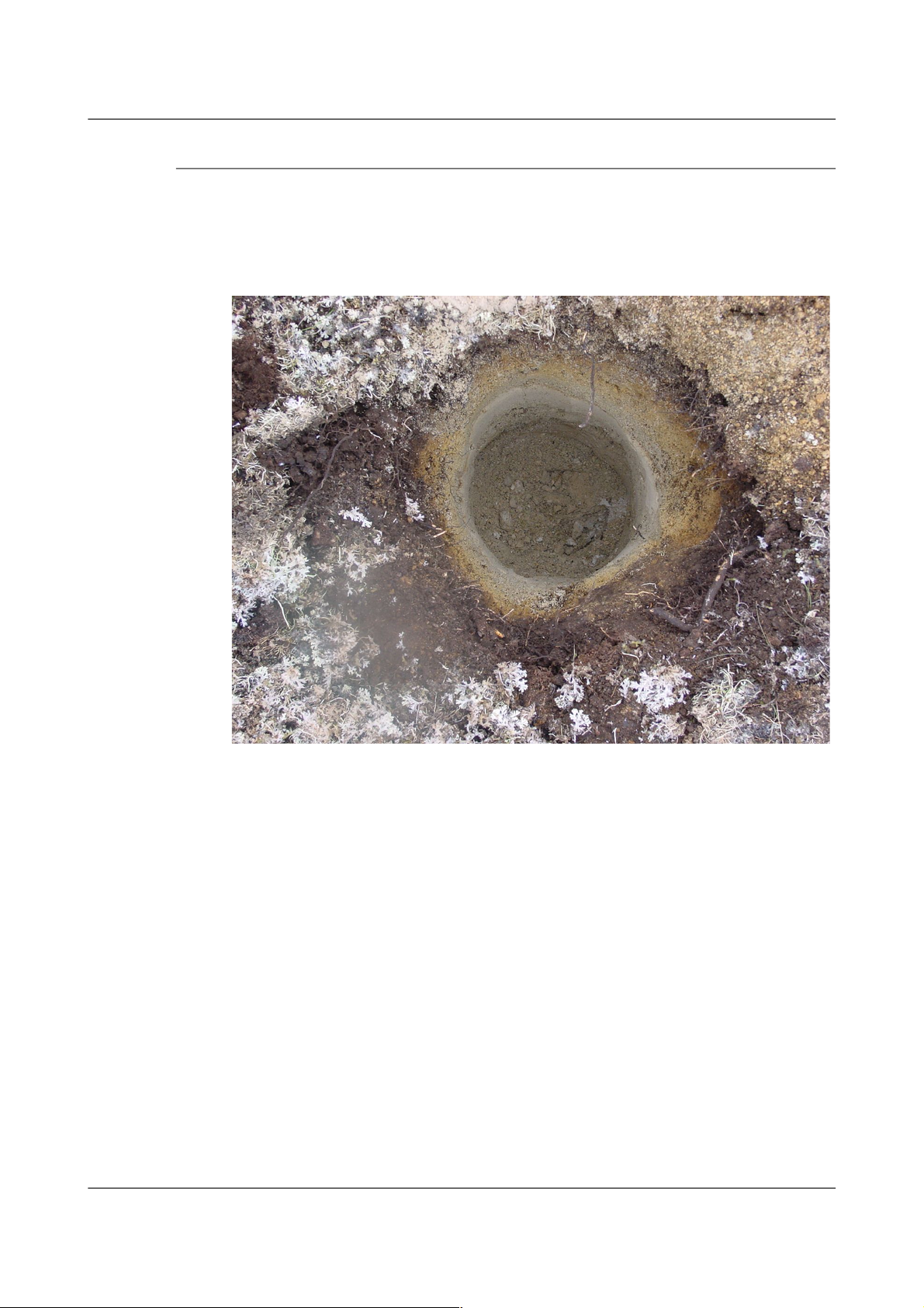
1. Prepare a hole of 60 – 90 cm depth to compacted subsoil, or down to
the bedrock if possible.
2. On granite or other hard bedrock, use an angle grinder to plane off the
bedrock at the pit bottom so that it is flat and level. Stand the
instrument directly on the bedrock, and go to step 7.
3. On soft bedrock or subsoil, you should install a pier as depicted below.
MAN-C3E-0002 14 Issue B - November 2013
Page 15
CMG-3ESPCD Digital Broadband Seismometer Installing the 3ESPCD
4. Pour a layer of loose, fine sand into the pit to cover the base. The type
of sand used for children's sand-pits is ideal, since the grains are clean,
dry and within a small size range. On top of the sand, place a smooth,
flat granite plinth around 20 cm across, and shift it to compact the sand
and provide a near-level surface.
Placing a granite plinth on a sand layer increases the contact between
the ground and the plinth, and improves the performance of the
instrument. There is also no need to mix concrete or to wait for it to
set, as in step 4.
5. Alternatively, if time allows and granite is not available, prepare a
concrete mix with sand and fine grit, and pour it into the hole. Agitate
(“puddle”) it whilst still liquid, to allow it to flow out and form a level
surface, then leave to set. Follow on from step 7.
Puddled concrete produces a fine-textured, level floor for emplacing
the seismometer. However, once set hard, the concrete does not have
the best possible coupling to the subsoil or bedrock, which has some
leeway to shift or settle beneath it.
6. Alternatively, for the most rapid installation, place loose soil over the
bottom of the pit, and compact it with a flat stone. Place the
MAN-C3E-0002 15 Issue B - November 2013
Page 16
CMG-3ESPCD Digital Broadband Seismometer Installing the 3ESPCD
seismometer on top of this stone. This method emulates that in step 3,
but can be performed on-site with no additional equipment.
7. Set up the instrument as described in Section 3.3 on page 11.
8. The instrument must now be shielded from air currents and
temperature fluctuations. This is best done by covering it with a
thermal shield.
An open-sided box of 5 cm expanded polystyrene slabs is
recommended. If using a seismic plinth on sand (from steps 3–4 or 5),
ensure that the box is firmly placed in the sand, without touching the
plinth at any point. In other installations, tape the box down to the
surface to exclude draughts.
9. Alternatively, if a box is not available, cover the instrument with fine
sand up to the top.
The sand insulates the instrument and protects it from thermal
fluctuations, as well as minimizing unwanted vibration.
10. Ensure that the sensor cable is loose and that it exits the seismometer
enclosure at the base of the instrument. This will prevent vibrations
from being inadvertently transmitted along the cable.
11. Cover the pit with a wooden lid, and back-fill with fresh turf.
3.5 Other installation methods
The recommended installation methods have been extensively tested in a
wide range of situations. However, past practice in seismometer installation
has varied widely.
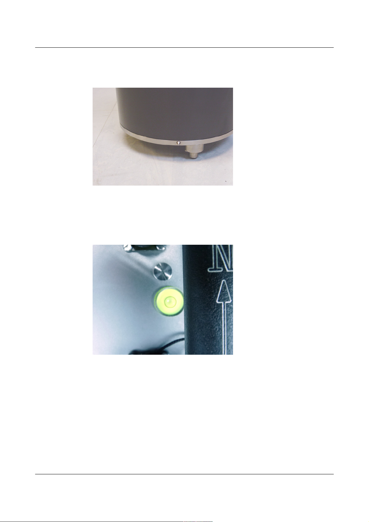
Some installations introduce a layer of ceramic tiles between a rock or
concrete plinth and the seismometer, as shown in the left-hand picture below:
However, noise tests show that this method of installation is significantly
inferior to the same concrete plinth with the tiles removed (right). Horizontal
sensors show shifting due to moisture trapped between the concrete and
tiling, whilst the vertical sensors show “pings” as the tile settles.
MAN-C3E-0002 16 Issue B - November 2013
Page 17
CMG-3ESPCD Digital Broadband Seismometer Installing the 3ESPCD
Other installations have been attempted with the instrument encased in
plaster of Paris, or some other hard-setting compound (left):
Again, this method produces inferior bonding to the instrument, and moisture
becomes trapped between the hard surfaces. We recommend the use of fine
dry sand (right) contained in a box if necessary, which can also insulate the
instrument against convection currents and
temperature changes. Sand has the further
advantage of being very easy to install,
requiring no preparation.
Finally, many pit installations have a large
space around the seismometer, covered with
a wooden roof. Large air-filled cavities are
susceptible to currents which produce
lower-frequency vibrations, and sharp edges
and corners can give rise to turbulence. We
recommend that a wooden box is placed
around the sensor to protect it from these
currents. The emplacement may then be
backfilled with fresh turf to insulate it from
vibrations at the surface, or simply roofed as
before.
By following these guidelines, you will
ensure that your seismic installation is ready to produce the highest quality
data.
3.6 Rapid installation
This section details a method of deploying 3ESPCD instruments with the
minimum of additional equipment. This is recommended for situations
where seismic instrumentation needs to be installed very quickly, e.g. to study
a resumption of volcanic activity, or where difficulty of access to the site
prevents you from constructing a full seismic pit. You should always
construct a pit if possible (see Section 3.4 on page 14), since the data
produced will be of significantly higher quality.
MAN-C3E-0002 17 Issue B - November 2013
Page 18
CMG-3ESPCD Digital Broadband Seismometer Installing the 3ESPCD
3.6.1 Deployment
1. Prepare a hole of 60 – 90 cm depth to compacted subsoil, or down to
the bedrock if possible.
2. Clean the hole down to the bottom, and remove any loose material from
the mouth. Ensure that the bottom of the hole is relatively flat.
3. If the bottom of the hole is made of hard rock, you may need to put in
some loose sand or soil so that the sensor can be levelled.
4. Connect the sensor to cables for the GPS unit and power source.
MAN-C3E-0002 18 Issue B - November 2013
Page 19

CMG-3ESPCD Digital Broadband Seismometer Installing the 3ESPCD
5. Carefully insert the instrument into the hole, protected by a tough
plastic bag to keep water out. Use a bag strong enough to bear the
weight of the sensor and breakout box, so that it can be recovered
easily.
6. Press the sensor down firmly into the soil, without tapping or hitting it.
7. Check the bubble level on top of the instrument package. Adjust the
instrument's position if necessary so that the bubble lies entirely within
the black circle.
8. Pack soil or sand around the instrument to hold it steady. Make sure
the soil or sand is firmly compacted and not at all loose.
9. Recheck the bubble level. If you cannot adjust the soil packing at this
stage and the sensor is not level, you will need to clear the hole and
restart from step 3.
10. Power the sensor and connect it to a laptop. Unlock the masses using
Scream's Control window.
11. Place the breakout box and any excess cable on top of the sensor, inside
the plastic bag.
MAN-C3E-0002 19 Issue B - November 2013
Page 20
CMG-3ESPCD Digital Broadband Seismometer Installing the 3ESPCD
12. Group the cables coming from the bag for a distance of about 1 m, and
keep them together with insulating tape.
13. Tie the top of the package and fold it over so that water cannot get in.
Leave any excess cable within the bag.
14. Cover the installation with soil or sand until it is no longer visible.
15. Attach a GPS unit to the cable coming from the sensor. Seal the
connection between the data cable and the GPS unit's IEEE 1394 cable
inside a plastic bag to protect it from moisture.
16. Position the GPS unit so that it has a good view of the sky. Bury the
cable and connector package so that they cannot be seen.
17. If possible, place the GPS near the instrument so that it can be found
more easily, and the connector package near the GPS so you can
retrieve data from the instrument without affecting the installation.
18. If you are using a battery as a power source, dig a second hole for it.
This hole does not need to be as deep as the pit for the instrument—
perhaps 10 cm plus the height of the battery.
MAN-C3E-0002 20 Issue B - November 2013
Page 21

CMG-3ESPCD Digital Broadband Seismometer Installing the 3ESPCD
19. Attach the sensor power cable to the battery, and wrap it in another
plastic bag. Place the bag in the hole.
20. Tie the bag and fold over, to make the battery as waterproof as possible.
21. Bury the power cable between the battery and the instrument, and
compact soil or sand around the bag.
22. Fill in and cover the hole so that it is not visible.
3.6.2 Recovery
Care should be taken when recovering the 3ESPCD, since tapping or banging
it can cause damage to the sensors inside. The following instructions assume
that you have installed the instrument following the steps above.
1. Find the GPS receiver, which will be the only feature visible from the
surface, and follow the buried data cable from it to the instrument.
2. Carefully remove earth from the hole until you find the power cable
coming from the instrument.
3. Follow the power cable to the battery pit, and carefully dig away the
soil to reveal the battery about 10 cm from the surface.
4. Connect a laptop to the data connector and, using Scream's Control
dialogue, lock the masses.
5. Disconnect the power cable from the battery. (With the power off, the
sensor is less likely to suffer electrical damage during recovery.)
6. Return to the location of the sensor, and dig down to it. You should be
able to remove a spade's head depth of soil without hitting the
instrument. Beyond that, using a small hand shovel, follow the wires
and carefully remove the remaining soil until you can see the plastic
bag. Take special care not to damage the wires, which should be tied
together in the vicinity of the bag.
MAN-C3E-0002 21 Issue B - November 2013
Page 22

CMG-3ESPCD Digital Broadband Seismometer Installing the 3ESPCD
7. Carry on removing soil, either with your hands or (very carefully!) with
the shovel, until the whole bag is uncovered to about half the height of
the instrument.
8. If the hole is relatively dry, open the bag and lift the instrument out by
its handle.
9. Alternatively, if the hole is waterlogged, carefully lift out the entire bag
in one piece, and remove the contents at the surface.
3.7 Installing in post-holes
The 3ESPCD is suitable for installation in potholes. In soft subsoil, a hole 2 –
4 metres deep and 20 cm wide can be conveniently excavated using a
tractor-mounted or hand-operated pothole auger. To minimize surface effects,
you should ensure that the hole is at least 1 metre deeper than the length of
the instrument, and preferably somewhat more.
Since the hole has no lining, it may occasionally flood. However, most soil
types are sufficiently permeable to allow water to soak away, leaving the
packing material moist.
To install a 3ESPCD in a pothole:
1. Clean the pothole, making sure there is no loose material around the
mouth of the hole or on its base.
2. Prepare the instrument package, making sure the inclinometer is
visible, and attach it to a winch or hoist by clamping a light steel cable
to the centre of the handle so that the package hangs vertically.
Connect the signal cable to the instrument.
3. Add packing material to the hole to about 15 cm depth. Fine crushed
rock, with a high proportion of rock flour and fine particles, makes
excellent packing material. Alternatively, a mixture of 3 mm grade
angular coarse grit with around 30% medium grit gives good results.
Moisten the packing material in the hole and ram firm.
4. Lower the instrument to the bottom of the hole, but without slackening
the lifting cable.
5. Fill more packing material around the instrument for about 30 cm,
moisten, and ram firm.
6. Use the bubble level to check that the instrument remains within its tilt
tolerance (± 2 °).
MAN-C3E-0002 22 Issue B - November 2013
Caution: Do not lift the instrument by any of the attached
cables. Straining the cables may result in invisible damage,
making future installations unreliable.
Page 23

CMG-3ESPCD Digital Broadband Seismometer Installing the 3ESPCD
7. Continue filling, moistening and packing until the instrument is
buried, checking that the tilt remains within tolerance.
8. Release the strain on the lifting cable, and allow the packing material to
settle for 24 hours.
9. If all is well after the settling period, release the lifting tackle, coil a tail
of the lifting wire into the top of the hole and backfill almost to the
surface.
10. Ensure that the signal cable is slack, and fix it to a support at the top of
the hole.
11. Ram a split wooden bung into the top of the hole, and cover with
sandbags.
12. Attach the signal cable to your laptop. Power the sensor, and unlock it.
Carry out preliminary tests using Scream!, if required.
3.8 Using the 3ESPCD
Once the 3ESPCD is powered, it will start producing data immediately. You
can now start configuring it for your own needs. There are three ways you
can do this:
• using the graphical interface provided by Scream! (see section 5 on page
39);
• using the web interface of a CMG-EAM (see MAN-EAM-0003); or
• over a terminal connection (see section 6 on page 60).
All three methods provide full access to the configuration options of the
digitiser.
3.8.1 Retrieving data
You can configure the digitiser to operate in a number of transmission modes.
These modes determine whether the unit stores data in its on-board Flash
memory, sends it over the serial link in GCF format, or does some
combination of these. See “Data flow ” in Section 5.2.5 on page 55 for more
details.
If you choose a transmission mode where some data are stored in Flash
memory, you will need to recover this data at a later date. You can do this
either over the serial link, or using the digitiser's FireWire interface.
To download data over FireWire, simply plug the disk in. If there are enough
new data waiting to be transferred (by default 128 Mb), they will immediately
be downloaded onto the disk. The internal pointers will be updated to mark
the data as downloaded.
MAN-C3E-0002 23 Issue B - November 2013
Page 24

CMG-3ESPCD Digital Broadband Seismometer Installing the 3ESPCD
Alternatively, for more downloading options, issue the command DISKMENU
from the digitiser's console before attaching the disk. See Section 6.7 on page
71 for more information. You can use DISKMENU to download any section of
data, whether or not it has already been transferred.
While the FireWire interface is active, it will consume about 200 mA of power
(from a 12 V supply). If you interrupt a transfer whilst in progress, the
digitiser will re-boot, but the data held in memory will not be affected.
To download data over the serial link:
1. Open the digitiser's console. To do this using Güralp Systems' Scream!
software, right-click on the digitiser's icon (once it appears) and select
Terminal....
Alternatively, from a Güralp EAM, issue the command
data-terminal
2. If you want to download all data held in the Flash memory, issue the
command
ALL-FLASH ALL-DATA DOWNLOAD
3. Alternatively, select a particular set of streams, sample rates and times
to download using the STREAM, S/S, FROM-TIME and TO-TIME
commands, and finish with DOWNLOAD. See Section 6.7 on page 71 for
more information.
4. Close the terminal session. If you are using Scream! or an EAM, the
digitiser should start transmitting immediately. Otherwise, you may
need to issue the command GO to start transferring data.
3.8.2 Reading digitiser disks
The digitiser uses a special disk format, DFD, for recording data. You can
read this data into a PC using Scream! or the GCFXtract utility, which is freely
available from the Güralp Systems Web site.
Güralp Systems can provide fully-tested disks with FireWire and USB
connectors. Alternatively, a third-party FireWire disk may be used (although
compatibility is not guaranteed.)
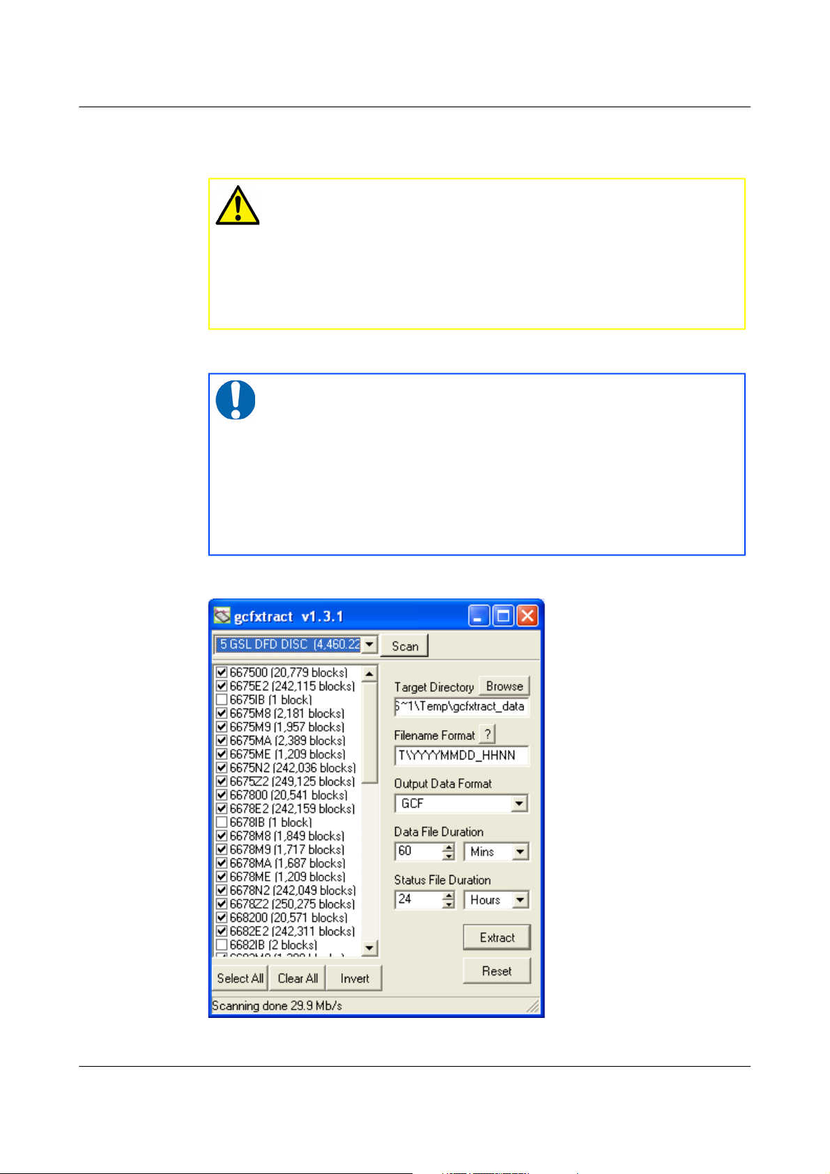
3.8.2.1 Reading disks with GCFXtract
To read a disk using GCFXtract:
MAN-C3E-0002 24 Issue B - November 2013
Note: The DFD format is not the same as that used by the Güralp
Systems EAM data modules, which use a FAT32-compatible or extn
journalling file system.
Page 25
CMG-3ESPCD Digital Broadband Seismometer Installing the 3ESPCD
1. Attach the disk to your computer. You can use FireWire, USB, or any
other interface supported by your computer and the disk.
2. Start GCFXtract
The following screen is displayed:
MAN-C3E-0002 25 Issue B - November 2013
Caution: Some operating systems, not recognising the DFD
format, will offer to re-format the disk when it is attached.
Always say NO: reformatting the disk will make the recorded
data unreachable and may over-write some of it. If you
accidentally allow the operating system to format a drive
containing valuable recorded seismic data, please contact
support@guralp.com for help.
Note: As GCFXtract requires raw disk device access, it must
be run with elevated privileges. On Windows 7 and
Windows Vista, it needs to “Run as Adminsitrator”. On
Windows XP, you need to be logged in as administrator. On
Linux, you need to run as root, or a user with read/write
permissions for raw disk devices. On most Linux systems,
you can grant these permissions with the command
sudo adduser user_name disk
Page 26

CMG-3ESPCD Digital Broadband Seismometer Installing the 3ESPCD
The program will first search for non-DOS disks on all the interfaces it
understands. If it does not find your disk, check that it is properly
connected and that any relevant drivers have been installed, then click
the button.
3. When you start up GCFXtract, the program searches all SCSI interfaces
and devices for DM24-format disk drives. The ID of each disk is
displayed in the drop-down list at the top of the window. Under each
disk, GCFXtract lists the transfer sessions it has found on the disk. The
DM24 creates a new transfer session each time it saves data to the disk.
You can extract data either from a single transfer session, or from the
entire disk.
4. Select the required disk or transfer session from the drop-down list, and
click . GCFXtract will scan the disk and display all the streams it
finds in the selection area below. For each stream, the Stream ID and the
number of blocks found are shown. This operation requires roughly
12 Mb of available memory for every Gb of space on the disk. If you
have a very large disk, your computer may have to use its hard disk to
make enough space. This will slow down scanning considerably.
5. By default, all streams containing more than 100 blocks are selected for
extraction. You can change which streams to extract by ticking or
clearing the check-box beside each stream. You can tick or clear all of the
boxes using the and buttons. Clicking ticks all cleared
boxes, and clears all ticked boxes.
6. Enter a path name into the Target Directory field, or use the
button to find a directory. This will be used as the root directory for
extracted data. If it does not exist, GCFXtract will create it.
7. Enter a format string into the Filename Format field. The syntax is the
same as the format string in Scream! and full documentation is available
by pressing the button beside the format entry field in interactive
mode.
8. Normally, GCFXtract outputs GCF files, to ensure all the information in
the original data are retained. If you want to convert to a different
format, select it from the Output Data Format drop-down box.
GCFXtract can output in most of the formats supported by Scream!.
9. Data are automatically placed in time order and saved in multiple files,
each file containing a contiguous segment of data. By default, data
streams are recorded in files 60 minutes long. To change this to some
other number of minutes, alter the value in the Data File Duration (mins)
box. For data streams, if there is a gap in the data, GCFXtract will start a
new file anyway.
MAN-C3E-0002 26 Issue B - November 2013
Page 27

CMG-3ESPCD Digital Broadband Seismometer Installing the 3ESPCD
10. Status streams are also saved in multiple files, but have a default length
of 24 hours. To change this, alter the value under Status File Duration
(hours).
11. When you are happy with the settings, click to begin extracting
the data.
12. Clicking sets a flag on the disk which marks it as empty. Next
time a digitiser wants to transfer data, it will begin at the beginning of
the disk, overwriting the old data. When this happens, none of the old
data can be extracted with GCFXtract. Until then, however, you will still
be able to retrieve all the data.
3.8.2.2 Reading disks with Scream!
You can also read disks with Scream!. This allows you to view data in the
process of being transferred, but is slightly slower, because Scream! does not
read data in strict order. To read a disk with Scream!:
1. Attach the disk to your computer. You can use FireWire, USB, or any
other interface supported by your computer and the disk.
2. Run Scream!, and select File Setup... from the main menu. Select the →
Files tab.
3. Set the Base Directory, Filename Format and Data Format as required.
Also, if required, set the Post-processor and Granularity options to your
preference. Consult the Scream! documentation for details.
4. Select the Recording tab, and tick the Auto Record—Enable for Data
Streams and Auto Record—Enable for Status Streams check-boxes. Click
OK. Scream! will remember the recording options you set in steps 3 and
4 for later occasions.
5. Select File Read SCSI disk... from the main menu. Scream! will search →
for attached disks, and open a window with a list of all the streams it has
found.
6. Select the streams you want to replay, and click Open. The disk will
appear in the left-hand pane of Scream!'s main window, and the streams
you have selected will start playing into the stream buffer, as well as
being recorded.
7. When you have finished transferring the data, if you want to reset the
disk, select File Reset SCSI disk... from Scream!'s main menu. Select →
the disk you want to reset, and click OK.
More information is contained in the Scream! Manual, MAN-SWA-0001.
MAN-C3E-0002 27 Issue B - November 2013
Page 28

CMG-3ESPCD Digital Broadband Seismometer Calibrating the 3ESPCD
4 Calibrating the 3ESPCD
4.1 The calibration pack
All Güralp sensors are fully calibrated before they leave the factory. Both
absolute and relative calibration calculations are carried out. The results are
given in the calibration pack supplied with each instrument:
• Works Order : The Güralp factory order number including the
instrument, used internally to file details of the sensor's manufacture.
• Serial Number: The serial number of the instrument
• Date: The date the instrument was tested at the factory.
• Tested By: The name of the testing engineer.
There follows a table showing important calibration information for each
component of the instrument, VERTICAL, NORTH/SOUTH, and EAST/WEST.
Each row details:
• Velocity Output (Differential) : The sensitivity of each component to
velocity at 1 Hz, in volts per m/s. Because the 3ESPCD uses balanced
differential outputs, the signal strength as measured between the +ve
and –ve lines will be twice the true sensitivity of the instrument. To
remind you of this, the sensitivities are given as 2 × (single-ended
sensitivity) in each case.
• Mass Position Output : The sensitivity of the mass position outputs to
acceleration, in volts per ms-2. These outputs are single-ended and
referenced to signal ground.
• Feedback Coil Constant : A constant describing the characteristics of
the feedback system. You will need this constant, given in amperes per
ms-2, if you want to perform your own calibration calculations (see
below.)
• Power Consumption : The average power consumption of the sensor
during testing, given in amperes and assuming a 12 V supply.
• Calibration Resistor : The value of the resistor in the calibration
circuit. You will need this value if you want to perform your own
calibration calculations (see below.)
4.1.1 Poles and zeroes
Most users of seismometers find it convenient to consider the sensor as a
“black box”, which produces an output signal V from a measured input x. So
long as the relationship between V and x is known, the details of the internal
MAN-C3E-0002 28 Issue B - November 2013
Page 29

CMG-3ESPCD Digital Broadband Seismometer Calibrating the 3ESPCD
mechanics and electronics can be disregarded. This relationship, given in
terms of the Laplace variable s, takes the form
( V / x ) (s) = G × A × H (s)
In this equation
• G is the acceleration output sensitivity (gain constant) of the
instrument. This relates the actual output to the desired input over the
flat portion of the frequency response.
• A is a constant which is evaluated so that A × H (s) is dimensionless
and has a value of 1 over the flat portion of the frequency response. In
practice, it is possible to design a system transfer function with a very
wide-range flat frequency response.
The normalising constant A is calculated at a normalising frequency
value fm = 1 Hz, with s = j fm, where j = √–1.
• H (s) is the transfer function of the sensor, which can be expressed in
factored form:
In this equation, zn are the roots of the numerator polynomial, giving
the zeros of the transfer function, and pm are the roots of the
denominator polynomial giving the poles of the transfer function.
In the calibration pack, G is the sensitivity given for each component on the
first page, whilst the roots zn and pm, together with the normalising factor A,
are given in the Poles and Zeros table. The poles and zeros given are
measured directly at Güralp Systems' factory using a spectrum analyser.
Transfer functions for the vertical and horizontal sensors may be provided
separately.
4.1.2 Frequency response curves
The frequency response of each component of the 3ESPCD is described in the
normalised amplitude and phase plots provided. The response is measured at
low and high frequencies in two separate experiments. Each plot marks the
low-frequency and high-frequency cutoff values (also known as –3 dB or
half-power points).
MAN-C3E-0002 29 Issue B - November 2013
Page 30
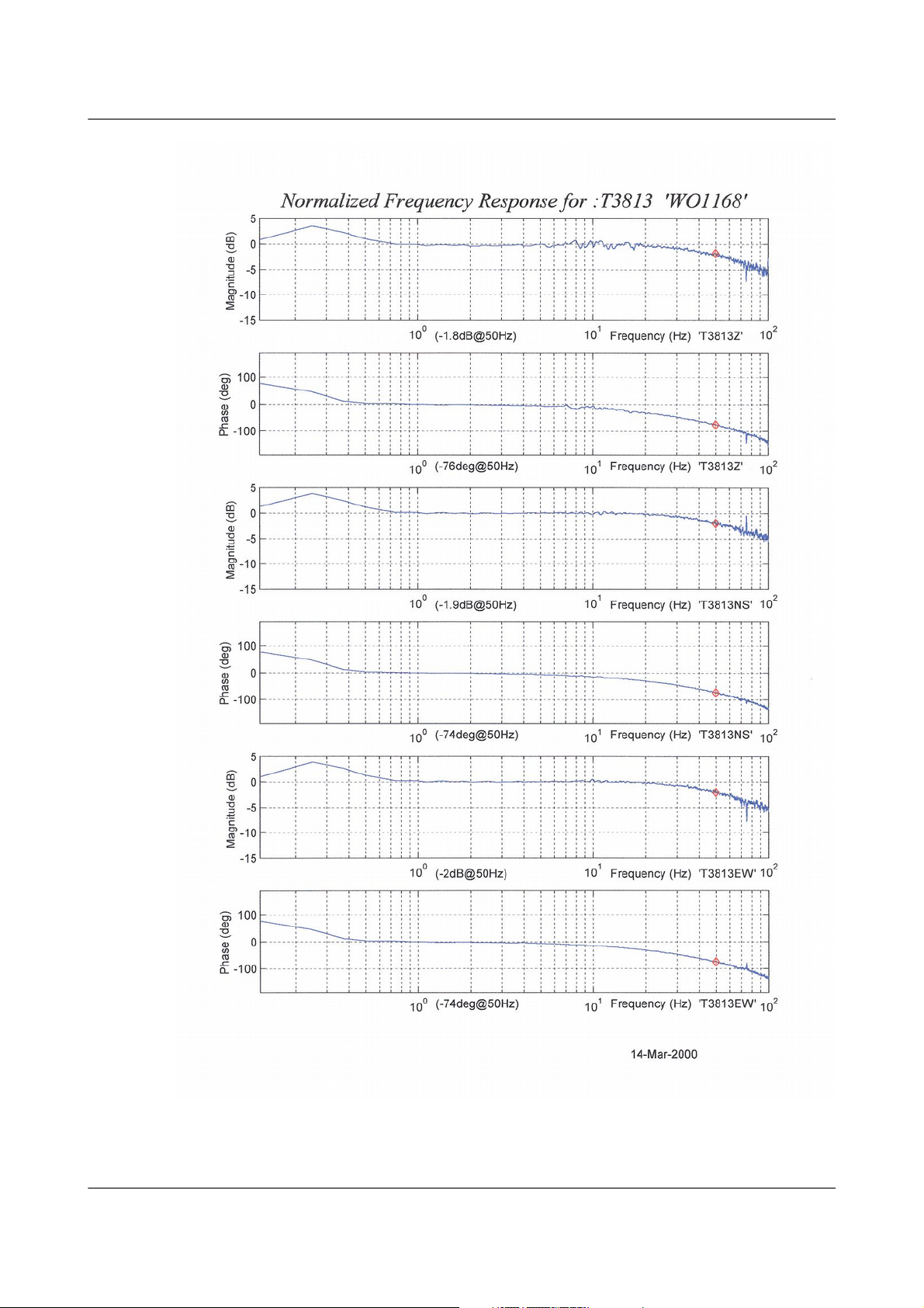
CMG-3ESPCD Digital Broadband Seismometer Calibrating the 3ESPCD
MAN-C3E-0002 30 Issue B - November 2013
Page 31

CMG-3ESPCD Digital Broadband Seismometer Calibrating the 3ESPCD
MAN-C3E-0002 31 Issue B - November 2013
Page 32

CMG-3ESPCD Digital Broadband Seismometer Calibrating the 3ESPCD
If you want to repeat the calibration to obtain more precise values at a
frequency of interest, or to check that a sensor is still functioning correctly,
you can inject calibration signals into the system using a Güralp digitiser or
your own signal generator, and record the instrument's response.
4.1.3 Obtaining copies of the calibration pack
Our servers keep copies of all calibration data that we send out. In the event
that the calibration information becomes separated from the instrument, you
can obtain all the information using our free e-mail service. Simply e-mail
caldoc@guralp.com with the serial number of the instrument in the subject
line, e.g.
The server will reply with the calibration documentation in Word format.
The body of your e-mail will be ignored.
4.2 Calibration methods
Velocity sensors such as the 3ESPCD are not sensitive to constant DC levels,
as a result both of their design and because of the interposed high-pass filter.
Instead, three common calibration techniques are used.
• Injecting a step current allows the system response to be determined in
the time domain. The amplitude and phase response can then be
calculated using a Fourier transform. Because the input signal has
predominantly low-frequency components, this method generally gives
poor results. However, it is simple enough to be performed daily.
MAN-C3E-0002 32 Issue B - November 2013
Page 33

CMG-3ESPCD Digital Broadband Seismometer Calibrating the 3ESPCD
• Injecting a sinusoidal current of known amplitude and frequency
allows the system response to be determined at a spot frequency.
However, before the calibration measurement can be made the system
must be allowed to reach a steady state; for low frequencies, this will
take a long time. In addition, several measurements must be made to
determine the response over the full frequency spectrum.
• Injecting broadband noise into the calibration coil gives the response of
the whole system, which can be measured using a spectrum analyser.
Calibration is performed using the built-in DM24 digitiser, which can
generate step and sinusoidal calibration signals as well as broadband noise,
and integrated scripts within Güralp Systems' Scream! software.
Initiating a calibration closes a relay which normally isolates the feedback
electronics from the calibration signal generator and causes signals of the
specified nature to be generated and routed through the feedback system. You
can then measure the signal's equivalent velocity using Scream!
4.3 Calibration with Scream!
Sine-wave, step and broadband noise calibrations are available. In this
section, broadband noise calibration will be used to determine the complete
sensor response in one action.
1. In Scream!'s main window, right-click on the digitiser's icon and select
Control.... Open the Calibration pane.
2. Select the calibration channel corresponding to the instrument, and
choose Broadband Noise. Select the component you wish to calibrate,
MAN-C3E-0002 33 Issue B - November 2013
Page 34

CMG-3ESPCD Digital Broadband Seismometer Calibrating the 3ESPCD
together with a suitable duration and amplitude, and click Inject now.
A new data stream, ending Cn (n = 0 – 7) or MB, will appear in
Scream!'s main window containing the returned calibration signal.
3. Open a Waveview window on the calibration signal and the returned
streams by selecting them and double-clicking. The streams should
display the calibration signal combined with the sensors' own
measurements. If you cannot see the calibration signal, zoom into the
Waveview using the scaling icons ( ) at the top left of the
window or the cursor keys.
If necessary, drag the calibration stream Cn up the Waveview window,
so that it is at the top.
4. If the returning signal is saturated, retry using a calibration signal with
lower amplitude, until the entire curve is visible in the Waveview
window.
5. If you need to scale one, but not another, of the traces, right-click on
the trace and select Scale.... You can then type in a suitable scale factor
for that trace.
6. Pause the Waveview window by clicking on the icon.
7. Hold down SHIFT and drag across the window to select the calibration
signal and the returning component(s). Release the mouse button,
keeping SHIFT held down. A menu will pop up. Choose “Broadband
Noise Calibration”.
MAN-C3E-0002 34 Issue B - November 2013
Page 35

CMG-3ESPCD Digital Broadband Seismometer Calibrating the 3ESPCD
8. The script will ask you to fill in sensor calibration parameters for each
component you have selected.
Most data can be found on the calibration sheet for your sensor. Under
Instrument response, you should fill in the sensor response code for
your sensor, according to the table below. Instrument Type should be
MAN-C3E-0002 35 Issue B - November 2013
Page 36

CMG-3ESPCD Digital Broadband Seismometer Calibrating the 3ESPCD
set to the model number of your instrument and Instrument Response
should be set to correct code, as given in section 4.3.1 on page 37,
followed by eirther “v” or “velocity”.
If the file calvals.txt exists in the same directory as Scream!'s
executable (scream.exe), Scream! will look there for suitable calibration
values. A sample calvals.txt is supplied with Scream!, which you
can edit to your requirements. Each stream has its own section in the
file, headed by the line [instrument-id]. The instrument-id is
the string which identifies the digitiser in the left-hand pane, e.g.
GURALP-DEMO. It is always 6 characters (the system identifier)
followed by a dash, then 4 characters (the serial number). For example:
[GURALP-DEMO]
Serial-Nos=T3X99
VPC=3.153,3.147,3.159
G=1010,1007,1002
COILCONST=0.02575,0.01778,0.01774
CALVPC=3.161
CALRES=51000
TYPE=sensor-type
RESPONSE=response-code
9. Click . The script will return with a graph showing the
responsivity of the sensor in terms of amplitude and phase plots for
each component.
The accuracy of the results depends on the amount of data you have
selected, and its sample rate. To obtain good-quality results at low
frequency, it will save computation time to use data collected at a lower
sample rate; although the same information is present in higher-rate
streams, they also include a large amount of high-frequency data which
may not be relevant to your purposes.
MAN-C3E-0002 36 Issue B - November 2013
Page 37

CMG-3ESPCD Digital Broadband Seismometer Calibrating the 3ESPCD
The bbnoisecal script automatically performs appropriate averaging
to reduce the effects of aliasing and cultural noise.
4.3.1 Sensor response codes
Sensor Sensor type code Units
(V/A)
CMG-3T or 3ESP, 30 s – 50 Hz response
CMG-3_30S_50HZ
V
CMG-3T or 3ESP, 60 s – 50 Hz response
CMG-3_60S_50HZ
V
CMG-3T or 3ESP, 100 s – 50 Hz response
CMG-3_100S_50HZ
V
CMG-3T or 3ESP, 120 s – 50 Hz response
CMG-3_120S_50HZ
V
CMG-3T or 3ESP, 360 s – 50 Hz response
CMG-3_360S_50HZ
V
CMG-3TB/3V/3ESP borehole, 30 s – 50 Hz
CMG-3B_30S_50HZ
V
CMG-3TB/3V/3ESP borehole, 100 s – 50 Hz
CMG3B_100S_50HZ
V
CMG-3TB/3V/3ESP borehole, 120 s – 50 Hz
CMG3B_120S_50HZ
V
4.4 The coil constant
The feedback coil constant K is measured at the time of manufacture, and
printed on the calibration sheet. Using this value will give good results at the
time of installation. However, it may change over time. The coil constant can
be determined by tilting the instrument and measuring its response to gravity.
To do this, you will need apparatus for measuring tilt angles accurately.
1. Measure the acceleration due to gravity, g, at your location.
2. Tilt the instrument slightly, and measure its attitude and the gain of the
mass position output for the component you wish to calibrate.
MAN-C3E-0002 37 Issue B - November 2013
Page 38

CMG-3ESPCD Digital Broadband Seismometer Calibrating the 3ESPCD
3. Repeat this measurement for several tilt angles.
4. For the vertical sensor, the input acceleration is given by
a = g sin φ
whilst for the horizontal sensor, it is
a = g ( 1 – cos )φ
Calculate the input acceleration for each of the tilt angles used, and
plot a graph of mass position output against input acceleration.
5. The gradient of the line obtained gives the sensitivity of the coil (in
V/ms-2, if g was measured in ms-2 and the mass position in V.)
6. The coil constant K is equal to this sensitivity divided by the value of
the displacement feedback resistor, given on the calibration sheet.
MAN-C3E-0002 38 Issue B - November 2013
Page 39

CMG-3ESPCD Digital Broadband Seismometer Using Scream!
5 Using Scream!
Scream! is a versatile seismic data visualisation program for Güralp
instruments, and is available for free download from Güralp Systems. See
http://www.guralp.com/scream/ for details about how to obtain Scream!.
5.1 Configuring digitisers
Scream! distinguishes between configuration and control of digitisers. The
most important difference is that a digitiser may be controlled through
Scream! at any time whilst it is acquiring data, whereas configuration options
only take effect after a reboot (with consequent loss of data). To change the
configuration of any connected digitiser:
1. Locate the digitiser you want to configure. All connected digitisers
have an entry in the tree on the left of Scream!'s main window. If the
digitiser is transmitting data through a remote server or EAM, you may
need to “unroll” the entry for that server (by clicking on the icon) to
see the digitisers connected to it.
2. Right-click on the digitiser's entry (not the icon for the server or any
Comxx icon). digitisers are shown with icons depicting a coloured
cylinder ( ).
3. Click Configure.... Scream! will then contact the digitiser and retrieve
its current configuration, a process which will take a few seconds. This
done, the Configuration set-up window will be displayed.
4. Once you are happy with any changes you have made in the
Configuration Set-up window, click UPLOAD to send them to the
digitiser and reboot. This will take a short while.
To control a digitiser whilst it is running, either right-click on the digitiser's
entry in the list and click Control..., or double-click the entry. In either case
Scream! will contact the digitiser to retrieve control information and display
the Control window. The options you can control immediately are:
• the type of sensor you are using,
• GPS power cycling options,
• the short-term and long-term average values for triggering (but not
which streams perform the trigger, or which are output by it - see
“Triggering” in section 5.1.3 on page 44),
• the length of pre-trigger and post-trigger periods,
• calibration signal options, and
• mass control functions.
MAN-C3E-0002 39 Issue B - November 2013
Page 40

CMG-3ESPCD Digital Broadband Seismometer Using Scream!
Some of these options can also be altered in the Configuration set-up window.
For more information on the Control window, see section 5.2 on page 53.
If you need a more powerful interface to the digitiser, you can also issue
commands to it directly using Scream!'s terminal mode. A terminal window
is opened by right-clicking on the digitiser's entry in the list and selecting
Terminal.... The digitiser will stop collecting data while you have a terminal
window open. The remaining sections of this chapter describe in detail the
configuration options available for the digitiser. Many of these options will
also be available for other Güralp digitisers
5.1.1 System ID
The System ID pane gives information about the digitiser and its internal
software, and allows you to change GPS timing parameters.
• System Identifier and Serial Number : The digitiser type is identified
by its system identifier and serial number. Every data and status block
generated by the digitiser includes these two fields at the beginning, so
that the block’s origin can be identified. On delivery from the factory,
the system identifier and the serial number are set to the GSL works
order number and the digitiser’s serial number, but any combination of
letters A-Z and numbers can be used, such as an abbreviation of your
institution’s name, etc. The system identifier can be up to 6 characters
long, whilst the serial number cannot be longer than 4.
• Sensor Type : If the sensor attached to the digitiser is a Güralp velocity
sensor, useful seismometer functions (such as sensor locking, centring,
and calibration) may be controlled through the digitiser. The Sensor
MAN-C3E-0002 40 Issue B - November 2013
Page 41

CMG-3ESPCD Digital Broadband Seismometer Using Scream!
Type you set here determines which functions will be available
through the Scream! digitiser configuration set-up interface or through
interactive commands. The correct value for your 3ESPCD is
“CMG-3T / ESPC”
• GPS Type : The digitiser needs to be able to time-stamp accurately all
data that passes through it. It can set its clock either by receiving time
signals from the GPS satellite network using an attached
Garmin-compatible (NMEA output) unit, or by taking time information
from a central site (stream sync mode). In stream sync mode, the
digitiser expects to receive two-byte packets from the central timing
source, which may have its own GPS unit, or take signals from one of
the radio time standards. Choose the mode you require from the
drop-down menu.
• Enable GPS power cycling : If you are using a GPS unit to receive time
signals, but do not experience significant drift in the system's clock (for
example, in a stable-temperature environment), you can save power by
selecting Enable GPS power cycling. With this option in use, the GPS
time is only checked at intervals of a specified number of hours.
Disabling this option keeps the GPS unit running constantly; if you
have ample power, this will give the most accurate results. You can
choose any whole number of hours for the interval.
5.1.2 Output control
The Output control tab allows you to configure which data streams are sent to
Scream! from the digitiser.
MAN-C3E-0002 41 Issue B - November 2013
Page 42

CMG-3ESPCD Digital Broadband Seismometer Using Scream!
Güralp digitisers initially sample incoming data at a high rate (e.g. 512,000 Hz
for the DM24), which is then filtered and reduced to a lower rate (decimated)
using an on-board digital signal processing unit, or DSP. The DSP has several
filtering-decimation stages, which run one after the other. Stages which can
produce output are called taps. The Güralp DM24 can output 4 taps
simultaneously. The input to the tap chain is fixed at 2,000 samples per
second.
Each configurable tap can be set to a different decimation factor by choosing
values from the drop-down menus on the left. Decimation factors of 2, 4, 5, 8,
and 10 are available. The numbers visible in the drop-down menu of each tap
are the data rates that each of the possible decimation factors will provide,
given the settings of the taps above it. Only integer (Hz) data rates are
allowed: thus, for example, if one tap emits data at 25 Hz, the only possible
further decimation factor is 5.
To the right of each decimation factor menu is a grid of check-boxes. These
boxes mark which streams of data to generate at each sample rate. The
screen-shot above shows a possible configuration for a triaxial instrument.
Every channel of the digitiser may be output at any tap; currently, all three
axes are being output at Tap 2 (20Hz).
MAN-C3E-0002 42 Issue B - November 2013
Note: If you want to change the names used for the channels, click
in the white box containing a Z in the above picture, and type a
letter or number. It will name the channels with a sequence of
letters or numbers beginning with the one you choose (e.g. A, B, C;
2, 3, 4; 9, A, B), unless you type Z in which case they will revert to
Z, N, and E.
Page 43

CMG-3ESPCD Digital Broadband Seismometer Using Scream!
Each combination of channel and tap has two check-boxes. The upper
check-box of each pair activates continuous output, whilst the lower activates
triggered output. In the example above, the digitiser will output data
continuously for all three channels at Tap 2, but never for any other taps. If
you do not need all the streams to output at all rates, you should leave boxes
clear to save communications capacity. You cannot tick both continuous and
triggered output for the same channel and tap.
When you enable a triggered stream, the digitiser will output data in that
stream only when a particular set of trigger criteria are met. This is shown
diagrammatically as data passing through a switch. In the example above, we
might want the high-rate data from Tap 0 to be generated only when an event
registers at some other tap. To do this, the lower check-boxes of Tap 0 should
be ticked.
With this configuration uploaded, Tap 2 will continue to produce output at all
times, but Tap 0 will also emit data whenever the trigger criteria are met. The
Triggering button is now shown in red to remind you that the trigger is active.
Every ticked box in this window will give rise to a data stream coming from
the digitiser, which will be displayed in Scream!'s main window when
Scream! first receives some data from it. Every stream is identified by a
6-character code, where the first four characters identify the digitiser, and the
last two characters identify the individual stream. The first four characters
are set by default to the serial number of the digitiser; you can change this on
the System ID pane (see section 5.1.1 on page 40) or from the digitiser's
console.
Using the example above, there are three data streams, Z, N and E, which each
output data at 20 samples/s (continuously) and 200 samples/s (occasionally).
In this example: •
• DA79 is the serial number of the digitiser.
• Z0, N0, E0 correspond to input channels Z, N, and E, output through
Tap 0.
MAN-C3E-0002 43 Issue B - November 2013
Page 44

CMG-3ESPCD Digital Broadband Seismometer Using Scream!
• Z4, N4, E4 correspond to input channels Z, N, and E, output through
Tap 2. A six-channel digitiser connected to two triaxial instruments
will use Z0, N0, E0, Z1, N1, E1 for tap 0; Z2, N2, E2, Z3, N3, E3 for
tap 1; Z4, N4, E4, Z5, N5, E5 for tap 2; and Z6, N6, E6, Z7, N7, E7 for
tap 3. The digitiser in the example has only one triaxial instrument
connected to it, so Z/N/E1, 3, 5 and 7 are unused.
• 00 is the digitiser status stream (notice: zero sample rate).
Other streams you may see include •
• M8, M9, MA: slow-rate Mux channels reporting the sensor mass
positions for the Z, N, and E components (“Mux Channels” in Section
4.1).
• ME: another Mux channel, normally used for reporting the digitiser's
internal temperature.
• CD, BP, IB: digitiser streams for specialised use.
5.1.3 Triggering
In its standard configuration, the digitiser outputs continuous data at a
sample rate you specify. In addition to this, Güralp digitisers can run a
triggering algorithm on the data they acquire. This allows you to record data
continuously at a relatively low sample rate, but record at a much higher
sample rate during short periods when the trigger is active. The parameters
controlling the triggering algorithm, and controlling the data output once the
system is triggered, are all selectable by the user, permitting maximum
flexibility of operation and the most efficient use of available storage space.
The digitiser can be set up for triggered output, that is, to output certain data
streams only when a particular trigger criterion is met. The trigger criterion
can be tested with data from the same or some other stream. For example,
you could use a later tap (with a lower sample rate) as a trigger for output
from an earlier, more detailed tap. Scream! also allows you to configure each
digitiser to receive triggers from other digitisers.
To create a new stream with a trigger, open Scream!'s digitiser configuration
window for the relevant digitiser, and click on the Output control tab. In the
Output control pane, a tap which gives rise to a triggered stream has a tick in
the lower row of its grid of check-boxes. You cannot configure the trigger
criteria until you have selected at least one stream to be affected by the trigger.
Once you have decided which streams should be output when the trigger is
activated, you will be able to click on the Triggering button to describe the
trigger condition. Alternatively, click on the Triggering tab at the top of the
window. Either action will open the Triggering pane:
MAN-C3E-0002 44 Issue B - November 2013
Page 45

CMG-3ESPCD Digital Broadband Seismometer Using Scream!
There are two triggering algorithms which Güralp digitisers can use: STA/LTA
and level-triggering. In addition, software and external triggering options are
available.
5.1.3.1 STA/LTA
The STA/LTA algorithm applies a simple ( short-term average ÷ long-term
average ) calculation to the triggering stream. It works by identifying sections
of an incoming data stream when the signal amplitude increases. The
purpose of taking a short term average, rather than triggering on signal
amplitude directly, is to make it less likely that spurious spikes will trigger
the device. Averaging also introduces an element of frequency selectivity into
the triggering process.
You can select which tap is tested for the trigger from the Data source
drop-down menu. The tap does not have to output data to Scream! for you to
be able to use it here.
Any or all of the channels available at that tap may be used to determine a
trigger. You can select which channels are considered by ticking the boxes in
the Channel column of the table. If any of the ticked channels passes the
trigger condition, the trigger will activate, and will not de-trigger until all of
the ticked channels have fallen below their respective ratio values.
The STA and LTA columns allow you to set the intervals over which the two
averages are calculated, in seconds. Typically, the time interval for the short
term average should be about as long as the signals you want to trigger on,
while the long term average should be taken over a much longer interval.
Both the STA and LTA values are recalculated continually, even during a
MAN-C3E-0002 45 Issue B - November 2013
Page 46

CMG-3ESPCD Digital Broadband Seismometer Using Scream!
trigger. The Ratio column determines by what factor the STA and LTA must
differ for the trigger to be passed. Finding the ratio most suited to your needs
is best done by experiment. Too high a value will result in events being
missed, while too low a value will result in spurious non-seismic noise
triggering the system. Like the averages, their ratio is continuously
recalculated for all components. Note that none of the boxes are allowed to be
empty, and so you will need to enter the new value before removing the old
one. Alternatively, you can use the up and down cursor keys to change the
values.
MAN-C3E-0002 46 Issue B - November 2013
Page 47

CMG-3ESPCD Digital Broadband Seismometer Using Scream!
For example, setting the STA to 1 second, the LTA to 10 seconds and the Ratio
to 4 would give rise to the following trigger behaviour:
Usually, the values of the STA and LTA periods, and of the Ratio, will be the
same for all selected channels. For convenience, Scream! will automatically
fill in other values to match ones you enter. If you want to use different
values for some channels, you should clear the “Common values” check-box
before altering them.
Once you have enabled the STA/LTA triggering method on a particular
channel, you can use the Control window to change the values of the STA and
MAN-C3E-0002 47 Issue B - November 2013
Page 48

CMG-3ESPCD Digital Broadband Seismometer Using Scream!
LTA periods, together with the Ratio, without restarting the digitiser (see
section 5.2 on page 53).
Since it is not generally advisable to trigger from broadband data, the digitiser
provides a set of standard bandpass filters to apply to the data streams before
they are tested for the trigger condition. This filtering serves to maximise
sensitivity within the frequency band of interest, and filter out noise outside
this band. You can select which bandpass filter to use from the Bandpass
filter drop-down menu. The corner frequencies of the pass band of the filter
are determined by the Nyquist frequency, which is given by the sampling rate
of the triggering data. The three filter options have pass bands between 10%
and 90%, between 20% and 90% and between 50% and 90% of the data’s
Nyquist frequency, respectively.
The possible filter configurations are shown in the following table:
Tap # Rate
(samples/s)
Bandwidth 1
(Hz)
Bandwidth 2
(Hz)
Bandwidth 5
(Hz)
0 200 10 – 90 20 – 90 50 – 90
1 100 5 – 45 10 – 45 25 – 45
50 2.5 – 22.5 5 – 22.5 12.5 – 22.5
40 2 – 18 4 – 18 10 – 18
25 1.25 – 11.25 2.5 – 11.25 6.25 – 11.25
20 1 – 9 2–9 5–9
2 50 2.5 – 22.5 5 – 22.5 12.5 – 22.5
25 1.25 – 11.25 2.5 – 11.25 6.25 – 11.25
20 1 – 9 2–9 5–9
10 0.5 – 4.5 1 – 4.5 2.5 – 4.5
8 0.4 – 3.6 0.8 – 3.6 2 – 3.6
5 0.25 – 2.25 0.5 – 2.25 1.25 – 2.25
4 0.2 – 1.8 0.4 – 1.8 1 – 1.8
2 0.1 – 0.9 0.2 – 0.9 0.5 – 0.9
3 25 1.25 – 11.25 12.5 – 11.25 6.25 – 11.25
10 0.5 – 4.5 1 – 4.5 2.5 – 4.5
5 0.25 – 2.25 0.5 – 2.25 1.25 – 2.25
4 0.2 – 1.8 0.4 – 1.8 1 – 1.8
2 0.1 – 0.9 0.2 – 0.9 0.5 – 0.9
1 0.05 – 0.45 0.1 – 0.45 0.25 – 0.45
MAN-C3E-0002 48 Issue B - November 2013
Page 49

CMG-3ESPCD Digital Broadband Seismometer Using Scream!
As can be seen, the filter you choose defines the set of permissible sample
rates. The spectral amplitudes for the various frequency responses available
are shown in the figures below.
#
MAN-C3E-0002 49 Issue B - November 2013
Page 50

CMG-3ESPCD Digital Broadband Seismometer Using Scream!
5.1.3.2 Level
Using the Level triggering method, a trigger is generated whenever one of the
selected components reaches a certain level above the baseline. You can
select which tap is monitored from the Data source drop-down menu, and the
channel(s) to be considered from the Channel column of the table. The values
in the Level column are the number of counts above the baseline that channel
must reach before a trigger is generated.
As with the STA/LTA method, the values of the Level will often be the same
for all selected channels. If you want to use different values for some
channels, you should clear the Common values check-box before altering
them.
Once you have enabled the Level triggering method on a particular channel,
you can use the Control window to change the level at which the system
triggers without restarting the digitiser (see section 5.2 on page 53).
5.1.3.3 External triggering
When a digitiser or digital sensor triggers, it sends the trigger itself to
connected devices, as well as any extra data that it has been configured to
record. You can configure other digitisers to respond to this signal by
triggering in turn. This is an option which you can specify at the time of
manufacture. For further details, please contact support@guralp.com.
5.1.3.4 Pre-trigger and post-trigger recording
In order to capture all of a seismic event, it is often useful to be able to record
data immediately preceding the trigger. Güralp digitisers have an internal
buffer of some seconds which allows this data to be added to the triggered
stream. Pre-trigger data are particularly useful for emergent-type signals,
where the system does not trigger until one phase after the first arrival. In
addition, to ensure that the coda of each event is included, some seconds of
data are recorded after the system de-triggers.
MAN-C3E-0002 50 Issue B - November 2013
Page 51

CMG-3ESPCD Digital Broadband Seismometer Using Scream!
The two boxes at bottom right of the Triggering pane allow the user to set the
pre-trigger and post-trigger data intervals, in seconds. These values determine
the minimum length of time during which data will be saved before the
trigger condition occurs, and after it has lapsed. Regardless of the intervals
chosen, the data in the triggered streams will begin on a whole second.
5.1.4 Mux Channels
The digitiser provides a range of slow-rate auxiliary channels for reporting the
system's state of health and other diagnostic information, known as
multiplexed (“Mux”) channels. In the 3ESPCD configuration, three of these
are used to report the sensor mass position and another is used for measuring
the internal temperature of the digitiser.
The collection and transmission of these environmental channels is
controlled using the Mux Channels pane:
If a tick is placed in the box next to a channel, its data will be collected and
transmitted as a data stream in GCF format, just as with the normal data
channels. To indicate that the data comes from a Mux channel, the Stream ID
will take the form ****Mx, where M stands for Mux and x is a hexadecimal
integer (i.e. 0 – 9, and A – F for 10 through 15). Z, N/S and E/W Mass Position
Mux channels appear as M8, M9 and MA respectively. The digitiser also
monitors its internal temperature, which is reported on channel ME.
5.1.5 Ports
The Baud Rates pane of the Configuration set-up window allows you to
program the baud rate and stop bits for the digitiser's output port.
MAN-C3E-0002 51 Issue B - November 2013
Page 52

CMG-3ESPCD Digital Broadband Seismometer Using Scream!
The baud rate you choose must satisfy two conditions: •
• It must be high enough to allow all the transmission of all data
generated by the digitiser at the sampling rates you have chosen. For
three streams of data at 100 Hz, for example, 9,600 baud will usually be
sufficient. If you wish to transmit 200 Hz data, however, the baud rate
must be at least 19,200.
• It must be low enough to fit within the operating range of the telemetry
equipment you are using. While modern modems often offer transfer
rates up to 56 kBaud, the telephone or transmission lines may not
support these rates. The same holds true for radio telemetry.
Usually, the transmit and receive rates of the data port will be the same. If
not, you may select different data rates by removing the tick in the check-box
marked Identical TX/RX rates.
The Stop Bits option allows you to choose whether the serial link uses 1 or 2
stop bits. In most cases this can be left at 1, although 2 may be required if you
are sending data over ‘difficult’ transmission lines (for example, some types of
radio link). Using 2 stop bits will add a 10% overhead to the data.
You will also need to set the data rate for Scream's local serial port, as well as
for the EAM or other communications device (if you are using one). In
Scream!, you can configure a serial port by right-clicking on its icon (not that
of the digitiser) and selecting Configure... from the pop-up menu: for more
details, consult the on-line help or user guide for Scream!. If you are using an
additional communications device, you should consult its documentation to
learn how to set its baud rate.
MAN-C3E-0002 52 Issue B - November 2013
Page 53

CMG-3ESPCD Digital Broadband Seismometer Using Scream!
5.2 Controlling digitisers
To control a digitiser whilst it is running, either right-click on the digitiser's
entry in the list to the left of Scream!'s main window (not the Local or Comxx
icons) and click Control..., or simply double-click the entry. Scream! will
then contact the digitiser and retrieve its current status, a process which will
take a few seconds, after which the Control window will be displayed. Once
you are happy with any changes you have made in the Control window, click
to send them to the digitiser, where they will take effect
immediately.
This chapter describes the control options available to you for the digitiser.
Many of these options will also be available for other Güralp digitisers. For
the most accurate information, you should consult the Operator's Guide for
the digitiser or sensor you connect.
5.2.1 System
When the Control window is first opened, it will be showing the System pane.
Sensor Type: If the sensor attached to the digitiser is a Güralp velocity sensor,
you can send control commands to it from the Mass Control tab (see below).
Which functions are available on this tab depends on the Sensor Type you
have set here. The correct value for your 3ESPCD is “CMG-3T / ESPC”
If you change the Sensor Type, you may have to Apply the change, close the
Control window, and open a new one to access the Mass Control options.
MAN-C3E-0002 53 Issue B - November 2013
Page 54

CMG-3ESPCD Digital Broadband Seismometer Using Scream!
Enable GPS power cycling: If you are using a GPS unit to receive time signals,
but do not experience significant drift in the system's clock (for example, in a
stable-temperature environment), you can save power by selecting Enable
GPS power cycling. With this option in use, the GPS time is only checked at
intervals of a specified number of hours.
5.2.2 Triggering
The Triggering pane is very similar to the corresponding pane of the
Configuration set-up window although not all options are available, since
some require rebooting the digitiser. See “Triggering” in section 5.2.2 on page
54 for more details.
5.2.3 Calibration
You can check that your instrumentation is correctly calibrated by injecting
known signals into the sensor's feedback loop. The Calibration pane allows
you to do this once the sensors are installed. See section 4 on page 28 for
details.
5.2.4 Mass Control
The controls on this tab are used to centre, unlock, and lock the sensor
masses.
See section 7.1.2 on page 77 for more information.
MAN-C3E-0002 54 Issue B - November 2013
Note: Whether or not this tab is visible depends on the “Sensor
type” setting on the “System” tab. See section 5.2.1 on page 53.
Page 55

CMG-3ESPCD Digital Broadband Seismometer Using Scream!
5.2.5 Data flow
The digitiser operates in one of several transmission modes. These modes
relate to how the unit uses its Flash memory:
• as a simple data store, from which you can request data (FILING and
DUAL modes);
• as a buffer holding unacknowledged blocks, which are transmitted in
preference to real-time data (FIFO mode);
• as a buffer holding unacknowledged blocks, which are transmitted
whenever the channel is free but no real-time data blocks are ready
(ADAPTIVE mode);
• not at all (DIRECT mode).
Separate from these modes are buffering modes, which tell the unit what to do
when its Flash memory becomes full: either
• carry on, overwriting the oldest data held (RECYCLE), or
• stop writing and switch the digitiser transmission mode to DIRECT
(WRITE-ONCE).
You can switch between transmission modes in Scream! by right-clicking on
the digitiser and clicking on Control..., then navigating to the Data Flow pane:
Clicking Apply in this window immediately activates the transmission mode
you have selected—there is no need to reboot. If you prefer, you can use the
digitiser terminal to switch between transmission modes. The commands to
use, which take effect immediately, are given below.
MAN-C3E-0002 55 Issue B - November 2013
Page 56

CMG-3ESPCD Digital Broadband Seismometer Using Scream!
5.2.5.1 DIRECT
Syntax: DIRECT
Instructs the digitiser not to use Flash memory for storage. Instead, all data
are transmitted directly to clients. An instrument in DIRECT mode still
honours the GCF Block Recovery Protocol: a temporary RAM buffer always
holds the last 256 blocks generated and, if a client fails to receive a block, it
can request its retransmission. If you expect breaks in communication
between the instrument and its client to last more than 256 blocks, or if you
want the instrument to handle breaks in transmission (rather than relying on
the client to request missed blocks), you should use
• ADAPTIVE mode, if you want data to stay as near to real time as
possible (but do not mind if blocks are received out of order); or
• FIFO mode, if you need blocks to be received in strict order (but do not
mind if the instrument takes a while to catch up to real time.)
5.2.5.2 FILING
Syntax: FILING
Instructs the digitiser not to transmit blocks to clients automatically, but to
store all digitised data in the Flash memory. If you have chosen the RECYCLE
buffering mode (see below), the memory is used in circular fashion, i.e. if it
becomes full, incoming blocks begin overwriting the oldest in memory. If the
WRITE-ONCE mode is active, the instrument will switch to DIRECT mode
(see above) when the memory becomes full. You can retrieve blocks from an
instrument in FILING mode by connecting to its terminal interface and
issuing commands such as FLUSH, or through Scream! (see below).
5.2.5.3 Heartbeat messages
When in FILING mode, an instrument transmits “heartbeat” messages over its
data port. These short messages take the place of data blocks, and ensure that
programs such as Scream! know that an instrument is present. You can
change the frequency of heartbeat messages from Scream!'s Control window,
or with the command HEARTBEAT. You can tell Scream! to download new
data automatically whenever it receives a heartbeat message from an
MAN-C3E-0002 56 Issue B - November 2013
Page 57

CMG-3ESPCD Digital Broadband Seismometer Using Scream!
instrument in FILING mode. This is useful, for example, in autonomous
installations connected by intermittent modem links. To enable this feature:
1. Choose File Setup... from Scream!'s main menu, and navigate to the→
Recording pane.
2. Tick the Auto-upload on heartbeat check-box.
3. Click . Using FILING mode with Auto-upload on heartbeat
ensures that Scream! receives all new data whenever it can, regardless
of the configuration of any devices between you and the instrument.
5.2.5.4 FIFO (First In First Out)
Syntax: FIFO
Instructs the digitiser to begin writing blocks to Flash memory as for FILING
mode, but also to transmit data to clients. Data are transmitted in strict order,
oldest first; the digitiser will only transmit the next block when it receives an
explicit acknowledgement of the previous block. If the communications link
is only marginally faster than the data rate, it will take some time to catch up
with the real-time data after an outage.
If you want data to be transmitted in real-time where possible, but are worried
about possible breaks in communication, you should use ADAPTIVE mode
MAN-C3E-0002 57 Issue B - November 2013
Page 58

CMG-3ESPCD Digital Broadband Seismometer Using Scream!
instead. FIFO mode will consider a data block successfully transmitted once
it has received an acknowledgement from the next device in the chain. If
there are several devices between you and the instrument, you will need to set
up the transmission mode for each device (if applicable) to ensure that data
flow works the way you expect.
Like all the transmission modes, FIFO mode does not delete data once it has
been transmitted. You can still request anything in the Flash memory using
Scream! or over the command line. The only way data can be deleted is if
they are overwritten (in the RECYCLE buffering mode, see below) or if you
delete it manually.
5.2.5.5 ADAPTIVE
Syntax: ADAPTIVE
Instructs the digitiser to transmit current blocks to clients if possible, but to
store all unacknowledged blocks in the Flash memory and resend them, oldest
first, when time allows. ADAPTIVE mode is best suited for “real-time”
installations where the link between digitiser and client is intermittent or
difficult to access. If the communications link is only marginally faster than
the data rate, it will usually be busy transmitting real-time data. Thus, it may
take a while for the instrument to work through the missed blocks. In this
case, and if your client supports it, you may prefer to use the Block Recovery
Protocol to request missed blocks where possible.
Some software packages (most commonly Earthworm) cannot handle blocks
being received out of time order. If you are using such a package, ADAPTIVE
mode will not work, and may crash the software.
5.2.5.6 DUAL
Syntax: DUAL
MAN-C3E-0002 58 Issue B - November 2013
Page 59

CMG-3ESPCD Digital Broadband Seismometer Using Scream!
Instructs the digitiser to transmit any continuous streams directly to clients as
for DIRECT mode, but to store triggered data into Flash storage as for FILING
mode. If you choose DUAL mode but do not select any continuous streams
for output, the instrument will send heartbeat messages as for FILING mode.
Scream! can pick these up and download new data as necessary.
5.2.5.7 RE-USE / RECYCLE
Syntax: RE-USE
Instructs the digitiser to carry on using the current filing technique when the
Flash memory becomes full, overwriting the oldest data held. This buffering
mode is called RECYCLE in Scream!. For example, in DUAL mode with
RECYCLE buffering, the latest continuous data will be transmitted to you as
normal, and the latest triggered data may be retrieved from the Flash memory
using Scream! or the command line. However, if you do not download data
regularly from the Flash memory, you may lose older blocks. This mode thus
lets you define the end point of the data held by the instrument.
5.2.5.8 WRITE-ONCE
Syntax: WRITE-ONCE
Instructs the digitiser to stop writing data to the Flash memory when it is full,
and to switch to DIRECT mode automatically. For example, in FIFO mode
with WRITE-ONCE buffering, the station will transmit data to you
continuously, but also save it in the Flash memory until it is full. Once full,
the instrument will switch to DIRECT mode and continue transmitting,
though no further data will be saved. This mode thus lets you define the start
point of the data held by the instrument.
MAN-C3E-0002 59 Issue B - November 2013
Page 60

CMG-3ESPCD Digital Broadband Seismometer Command line interface
6 Command line interface
6.1 Introduction
You can connect to the internal software of the digitiser over its output serial
port and communicate with it. To enter command mode from Scream!,
right-click on the digitiser's icon and select Terminal... from the menu that
pops up. A window will open, and once the digitiser and computer are
communicating properly you will see the prompt
ok
If you prefer, you can use a terminal program on your computer (such as
minicom on Linux, or PuTTY on Microsoft Windows) to connect to the
digitiser.
Whilst you are in terminal mode, data transfer will be interrupted; the
digitiser may use any Flash memory as a temporary store, depending on how
you have configured it. Some commands, such as SET-TAPS, require a reboot
to take effect.
Güralp EAM and AM modules also allow you to send commands directly to
the digitiser using command-line and/or web-based tools. For more
information, please see the manual for your data module.
If you have problems connecting to the digitiser's console, you should check
that the serial port's options and baud rate are set correctly in Scream! or your
terminal program. As supplied, the digitiser expects connections at 19200
baud, with 8 data bits, no parity bit and 1 stop bit. No flow control is used.
6.1.1 FORTH
The digitiser uses FORTH to implement its features. To issue a command in
FORTH, you must supply the arguments before the command, for example:
3 SENSOR-TYPE
In FORTH, anything you enter is termed a “word”. New words (case
insensitive) are placed on a stack. Some words are known to the system, and
may represent commands; if a command finds itself at the top of the stack
(e.g. because it is the last thing you typed), they will execute, remove
themselves from the stack, and then remove further items from the stack to
use as arguments. Thus, in the command
3 SENSOR-TYPE
the 3 has no immediate effect, so stays on the stack; SENSOR-TYPE takes itself
and the previous item (here 3) off the stack, then performs its action on the 3
(here, setting the configured sensor type to 3, representing a CMG-3T sensor.)
MAN-C3E-0002 60 Issue B - November 2013
Page 61

CMG-3ESPCD Digital Broadband Seismometer Command line interface
If a command completes with nothing remaining on the stack, the digitiser
will show the prompt ok. Otherwise, the prompt will remind you that the
digitiser is waiting for you to complete the command. Some commands, such
as SAMPLES/SEC, clear the stack automatically after they execute.
Some commands are interactive, and will ask you to provide extra
information after you execute them. In the following sections, interactive
commands are shown as example sessions, using the typographical
conventions given in section 1.4 on page 5.
6.2 General configuration
The following commands set the general configuration of the digitiser.
6.2.1 SET-ID
Syntax: SET-ID (interactive)
Sets the system identifier and serial number of the digitiser to values you
supply:
SET-ID
System Identifier ? (e.g. ALPHA,) DM24ID, Serial # ?
(e.g. 1234,00) 4507,00
The system identifier that you supply may contain up to 6 alphanumeric
(0-9A-Z) characters, and must have a comma after it. 6-character strings
lexically greater than ZIK0ZJ are not permitted. The serial number you
supply must contain exactly 6 alphanumeric (09A-Z) characters, and must
have a comma after the fourth character.
6.2.2 SENSOR-TYPE
Syntax: type SENSOR-TYPE
Tells the digitiser which kind of sensor is attached to it. This affects whether
or not the digitiser exposes commands such as locking and centring. The
argument type can be one of
• 1, for CMG-40T sensors,
• 2, for CMG-3ESP sensors,
• 3, for CMG-3T analogue sensors, or
• 4, for CMG-3TD sensors.
6.2.3 GPS-TYPE
Syntax: type GPS-TYPE
MAN-C3E-0002 61 Issue B - November 2013
Page 62

CMG-3ESPCD Digital Broadband Seismometer Command line interface
Tells the digitiser which kind of GPS is attached to it. The argument type
can be one of
• 0, if no GPS is available,
• 1, for attached Trimble GPS equipment,
• 2, for attached Garmin GPS equipment, or
• 3, if GPS information should be obtained from upstream units (stream
sync mode.)
6.2.4 BAUD
Syntax: port baud-rate BAUD
Sets the baud rate for one of the serial ports on the digitiser, in bytes per
second. The argument port is a small integer specifying the port: Most units
have port 0 assigned to data output and communication, port 1 to GPS input,
and port 2 to the DATA IN port. For example,
0 38400 BAUD
1 4800 BAUD
2 38400 BAUD
This will reset a standard single-sensor digitiser to its default configuration.
The allowable values for baud-rate are 4800, 7200, 9600, 14400, 19200, 38400,
57600 and 1152 (for 115200 baud). GPS inputs should remain set at 4800
baud.
6.2.5 AZIMUTH
Syntax: instrument angle AZIMUTH
Some borehole digitisers can rotate incoming signals algorithmically as they
are digitised. This feature allows you to compensate for an instrument being
out of alignment with the North/South axis. To use it, first measure the
orientation of the sensor, then connect to the digitiser and issue an AZIMUTH
command, giving the angle you have measured.
The argument instrument tells the digitiser which instrument to apply the
rotation to; 0 for a 4-channel digitiser.
The argument angle is the measured angle of deviation from the North/South
axis, in tenths of a degree. The angle of deviation is the negative of the angle
by which you want incoming signals to be rotated. Like all other parameters,
it must be an integer (i.e. a whole number of tenths of a degree).
You can measure the orientation of a borehole sensor by placing a reference
sensor nearby and carrying out coherence calculations. An extension to
Scream! is available which can do this for you. For details, see the manual for
Scream!, MAN-SWA-0001.
MAN-C3E-0002 62 Issue B - November 2013
Page 63

CMG-3ESPCD Digital Broadband Seismometer Command line interface
The AZIMUTH command only alters the digitiser's CMOS settings. You will
need to re-boot the digitiser to transfer them to the DSP.
6.2.6 CROSS
Syntax: channel CROSS
Alters the DSP's transformation matrix to invert one of the digitiser channels.
The argument channel is one of 0 (vertical), 1 (N/S), 2 (E/W) and 3
(auxiliary).
The CROSS command only alters the digitiser's CMOS settings. You will
need to re-boot the digitiser to transfer them to the DSP. If you need to set
both AZIMUTH and CROSS, you must issue AZIMUTH first, since it overwrites
the matrix.
6.3 Output configuration
The commands in this section control the serial data output.
6.3.1 SAMPLES/SEC
Syntax: tap-0 tap-1 tap-2 tap-3 samples/sec
The DSP software on the digitiser supports up to 7 cascaded filter/decimation
stages. At each stage, the sample rate can be decimated by a factor of 2, 4 or 5.
The fixed decimation stages output data at 2,000 samples/sec, so decimated
data streams are available from 1,000, 500 and 400 samples/sec down to 1
sample/sec.
You can specify the sample rate to use at four of these stages, known as taps.
You can also take output from any of these four stages. The digitiser will
arrange the remaining stages according to your settings.
The arguments tap-0 to tap-3 are the sample rates at each tap in turn,
starting with the highest. You must ensure that each rate is lower than the
previous one by a factor of 2, 4, 5, 8 (= 2 then 4), 10 (= 2 then 5) or 16 (= 4
then 4). Non-integer values are not allowed. The following four examples are
all valid settings:
1000 125 25 5 samples/sec
1000 500 100 10 samples/sec
500 100 20 4 samples/sec
400 40 10 5 samples/sec
As long as you specify the initial taps, you can omit later ones. The command
fills in the value of the missing taps, using a decimation factor of 2 where
possible. Thus, the following commands are equivalent:
MAN-C3E-0002 63 Issue B - November 2013
Page 64

CMG-3ESPCD Digital Broadband Seismometer Command line interface
400 40 20 10 samples/sec
400 40 samples/sec
6.3.2 CONTINUOUS
Syntax: tap components CONTINUOUS
Sets which components are output under normal conditions, and at which
tap(s).
The argument tap is the tap number at which to output the triggered stream.
You can set which taps output which sample rates using the SAMPLES/SEC
command, described above.
The argument components is an integer below 16, whose binary bits
represent the Z (1), N (2), E (4) and auxiliary (8) components respectively.
Thus, for example,
• 0 1 CONTINUOUS will output the Z component only (1) at the first tap;
• 0 2 CONTINUOUS will output the N component only (2);
• 0 4 CONTINUOUS will output the E component only (4);
• 0 7 CONTINUOUS will output all three directional components (1 + 2
+ 4 = 7);
• 0 12 CONTINUOUS will output the E component and the auxiliary
component (4 + 8 = 12);
• 0 0 CONTINUOUS will output nothing at this tap.
6.3.3 SET-TAPS
Syntax: tap-0 tap-1 tap-2 tap-3 SET-TAPS
This is an alternative to the CONTINUOUS command, which allows you to set
the outputs for all taps simultaneously.
The arguments tap-0 to tap-3 are integers below 16, whose binary bits
represent the Z (1), N (2), E (4) and auxiliary (8) components respectively.
Each one sets which components are output at that tap under normal
conditions. For example, if you issue
9 7 0 15 SET-TAPS
then
• tap 1 will output Z and the auxiliary component ( 1 + 8 = 9 );
• tap 2 will output all three directional components ( 1 + 2 + 4 =7 );
• tap 3 will not output anything; and
MAN-C3E-0002 64 Issue B - November 2013
Page 65

CMG-3ESPCD Digital Broadband Seismometer Command line interface
• tap 4 will output all four components ( 1 + 2 + 4 + 8 = 15).
To set triggered output streams, you should use the TRIGGERED command
detailed below.
6.4 Triggering
This section describes the commands which affect triggering.
6.4.1 TRIGGERS
Syntax: components TRIGGERS
Selects which component or components can generate a trigger. Only these
components will be examined by the triggering algorithm.
The argument components is an integer below 16, whose binary bits
represent the Z (1), N (2), E (4) and auxiliary (8) components respectively as
described above. Issuing 0 TRIGGERS will disable the triggering system.
6.4.2 TRIGGERED
Syntax: tap components TRIGGERED
Selects which component or components will be output when a trigger is
generated, and at which tap (sample rate).
The argument tap is the tap number at which to output the triggered stream.
You can set which taps output which sample rate using the SAMPLES/SEC
command, described above.
The argument components is an integer below 16, which represents which
components to output in the same fashion as in the CONTINUOUS command,
above.
(This command and the previous one have similar names; remember that a
component TRIGGERS the system, whilst taps and components are
TRIGGERED.)
6.4.3 STA
Syntax: Z-secs N-secs E-secs X-secs STA
Sets the length of the “short-term” averaging period in the STA/LTA triggering
algorithm.
The arguments Z-secs, N-secs, E-secs and X-secs are the time period
over which to calculate the average for the Z, N, E, and auxiliary components
respectively. If a component is not considered by the triggering algorithm (see
TRIGGERS, above), the value you specify here will be ignored. For example,
1 1 2 2 STA
MAN-C3E-0002 65 Issue B - November 2013
Page 66

CMG-3ESPCD Digital Broadband Seismometer Command line interface
will calculate short-term averages for 1 second of the Z and N components,
and 2 seconds of the E and auxiliary components.
6.4.4 LTA
Syntax: Z-secs N-secs E-secs X-secs LTA
Sets the length of the “long-term” averaging period in the STA/LTA triggering
algorithm.
The arguments Z-secs, N-secs, E-secs and X-secs are the time period
over which to calculate the average for the Z, N, E, and auxiliary components
respectively. If a component is not considered by the triggering algorithm (see
TRIGGERS, above), the value you specify here will be ignored. For example,
15 20 20 20 STA
will calculate long-term averages for 15 seconds of the Z component and 20
seconds of the N, E and auxiliary components.
6.4.5 RATIOS
Syntax: Z-ratio N-ratio E-ratio X-ratio RATIOS
Sets the ratio of STA to LTA above which a trigger will be declared in the
STA/LTA triggering algorithm.
The arguments Z-ratio, N-ratio, E-ratio and X-ratio are the time
period over which to calculate the average for the Z, N, E, and auxiliary
components respectively. If a component is not considered by the triggering
algorithm (see TRIGGERS, above), the value you specify here will be ignored.
For example,
4 10 10 10 RATIOS
will cause the digitiser to trigger if the STA/LTA ratio is above 4 for the Z
component or above 10 for the remaining components.
6.4.6 PRE-TRIG
Syntax: time PRE-TRIG
Sets the pre-trigger recording time. The argument time is the number of
seconds of data to output from before a trigger is declared.
6.4.7 POST-TRIG
Syntax: time POST-TRIG
Sets the post-trigger recording time. The argument time is the number of
seconds of data to output after a trigger condition lapses. If an event persists
MAN-C3E-0002 66 Issue B - November 2013
Page 67

CMG-3ESPCD Digital Broadband Seismometer Command line interface
for some time, all triggering components must fall below the threshold before
the trigger condition will lapse; only then will the post-trigger period begin.
6.4.8 TRIGGERIN
Syntax: TRIGGERIN ENABLE | TRIGGERIN DISABLE
Enables or disables external trigger input, in instruments equipped with this
option.
Enabling external trigger input allows you to trigger the digitiser from an
external logic level supplied through its digital output port. This voltage can
be between 5 and 10 V supplied between the Trigger In pin and signal ground.
If the digitiser is triggered externally, it will behave exactly as if it had
generated the trigger itself.
6.4.9 TRIGGEROUT
Syntax: TRIGGEROUT ENABLE | TRIGGEROUT DISABLE
Enables or disables external trigger output, in instruments equipped with this
option.
Enabling external trigger output allows you to trigger other equipment
through a relay contained within the digitiser whenever it triggers. The
digitiser's digital output port contains two pins (Trigger out, common and
Trigger out, normally-open) which are connected when it triggers. In
particular, you can connect a second digitiser with TRIGGERIN ENABLE in
effect, in which case triggered data from both instruments will be transmitted
whenever the digitiser triggers.
If a digitiser has both TRIGGERIN ENABLE and TRIGGEROUT ENABLE in
effect, only triggers which the digitiser itself has generated will be output.
Triggers received through the Trigger in port will cause the digitiser to output
triggered streams, but will not be passed on to other digitisers.
6.5 Calibration
These commands are all concerned with calibration.
6.5.1 SINEWAVE
Syntax: component freq-or-period unit SINEWAVE
Instructs the digitiser to inject a sine-wave calibration signal, starting on the
zero crossing.
The argument component specifies which component is to be calibrated, one
of Z, N/S, E/W, or X. Some sensors use only the Z calibration loop for all
three components.
MAN-C3E-0002 67 Issue B - November 2013
Page 68

CMG-3ESPCD Digital Broadband Seismometer Command line interface
The arguments freq-or-period and unit together determine the frequency
of the calibration signal. If unit is HZ, then freq-or-period is taken as a
frequency, in Hz; if SECOND, then it is interpreted as a period, in seconds.
For example:
N/S 4 HZ SINEWAVE
The argument freq-or-period must be an integer; if you want to specify a
period of, for example, 0.5 s, you should specify it as 2 HZ instead. T he
calibration signal will be automatically disconnected after 2 minutes if you
have not altered the setting using the MINUTE command, described below.
Whilst calibration is in progress, the fourth (auxiliary, or X) data channel is
switched on to monitor the returning calibration signal.
6.5.2 SQUAREWAVE
Syntax: component SQUAREWAVE
Instructs the digitiser to inject a square-wave (step function) calibration
signal, consisting of a positive step on the start of the next clock minute,
followed by a negative step some minutes later (by default, 2). The calibration
is disconnected the same number of minutes after the negative edge.
The argument component specifies which component is to be calibrated, one
of Z, N/S, E/W, or X. Some sensors use only the Z calibration loop for all three
components. You can alter the duration of each step using the MINUTE
command, described below.
Whilst calibration is in progress, the fourth (auxiliary, or X) data channel is
switched on to monitor the returning calibration signal.
6.5.3 RANDOMCAL
Syntax: component RANDOMCAL
Instructs the digitiser to inject a white-noise calibration signal generated by an
on-board pseudo-random number generator.
The argument component specifies which component is to be calibrated, one
of Z, N/S, E/W, or X. Some sensors use only the Z calibration loop for all
three components.
The calibration signal will be automatically disconnected after 2 minutes if
you have not altered the setting using the MINUTE command, described
below.
Whilst calibration is in progress, the fourth (auxiliary, or X) data channel is
switched on to monitor the returning calibration signal. The pseudo-random
MAN-C3E-0002 68 Issue B - November 2013
Page 69

CMG-3ESPCD Digital Broadband Seismometer Command line interface
number generator produces true white noise over the entire passband, as
shown in the power spectral density plot below:
The different coloured lines show the results of experiments which measure
the power spectral density over several frequency bands. Together, the results
show a flat noise level over the entire passband to within experimental error.
6.5.4 MINUTE
Syntax: duration MINUTE
Sets for how long the next SINEWAVE or RANDOMCAL calibration signal will be
injected, or the period of the next SQUAREWAVE calibration signal.
The argument duration is the desired interval, in minutes. If you now issue
a SINEWAVE or RANDOMCAL command, the calibration will last duration
minutes; if the next calibration command is SQUAREWAVE, a positive step of
duration minutes will be generated, followed by a negative step of a further
duration minutes.
If you do not issue MINUTE, calibration signals will default to 2 minutes. This
is to avoid the sensor and digitiser inadvertently being left in calibration
mode. Issuing, e.g., 5 MINUTE will cause the next calibration signal to last 5
minutes, but later calibration signals will revert to a duration of 2 minutes.
You will need to issue a MINUTE command before each injection.
MAN-C3E-0002 69 Issue B - November 2013
Page 70

CMG-3ESPCD Digital Broadband Seismometer Command line interface
Because of the way FORTH works, you can insert MINUTE commands into
SQUAREWAVE, SINEWAVE or RANDOMCAL commands, for example:
N/S 4 HZ 5 MINUTE SINEWAVE E/W 10 MINUTE SQUAREWAVE
6.5.5 %AMPLITUDE
Syntax: value %AMPLITUDE
Sets the relative amplitude of the signal, as a percentage. For SQUAREWAVE
and RANDOMCAL calibrations, the default of 100% is normally suitable. If you
have a high-gain sensor, you may have to use a lower value. For SINEWAVE
calibrations, you may have to adjust the %AMPLITUDE setting to suit the
frequency of the calibration signal.
You can insert %AMPLITUDE commands into calibration commands as
described above, e.g.:
Z 3 MINUTE 50 %AMPLITUDE RANDOMCAL
6.6 Actions
The commands in this section trigger specific actions, such as mass-locking.
6.6.1 LOCK
Syntax: LOCK
Locks the sensor mass of the instrument. Whilst this process is executing, the
system displays the mass position for each component, measuring one
position each second (i.e. one reading every 4 seconds for each component of
a 4-component instrument). The process returns when locking is complete.
The mass positions are measured to 16-bit accuracy, with full deflection
corresponding to values around ±32000 counts.
6.6.2 UNLOCK
Syntax: UNLOCK
Unlocks the sensor mass, and returns when unlocking is complete. The
system will display the mass positions as the process continues, as for LOCK,
above.
6.6.3 CENTRE
Syntax: CENTRE
Centres the sensor mass, and returns when centring is complete. The system
will display the mass positions as the process continues, as for LOCK, above.
When the mass is correctly centred, the readings should be less than ±1000
counts.
MAN-C3E-0002 70 Issue B - November 2013
Page 71

CMG-3ESPCD Digital Broadband Seismometer Command line interface
6.6.4 RE-BOOT
Syntax: RE-BOOT (interactive)
Causes the digitiser to reset after a delay of 2 seconds.
RE-BOOT
Confirm with 'y' ? y
Responding to the confirmation message with anything other than y will abort
the reset.
6.7 Data storage and recovery
These commands control how data are stored, transmitted and recovered from
the internal flash storage.
6.7.1 SHOW-FLASH
Syntax: SHOW-FLASH
Reports status information about the Flash memory in the digitiser, if fitted.
For example, the SHOW-FLASH output for a new system with 8 × 64Mb chips
fitted might be
512MB Flash File buffer : 16 Blocks Written 0 unread
524,288 Free
Oldest data [16] Blank
Read point [16] Blank
Latest data [16] Blank
File Replay [16] Blank
Similarly, SHOW-FLASH on a system in use with 1 × 64Mb chip fitted might
display:
64MB Flash File buffer : 65,536 Blocks Written 65.532
Unread 4 Free
Oldest data [36,272] GURALP TESTZ1 2004 12 3 20:20:41
Read point [36,272] GURALP TESTZ1 2004 12 3 20:20:41
Latest data [36,268] GURALP TESTX2 2004 12 4 10:09:12
File Replay [36,272] GURALP TESTZ1 2004 12 3 20:20:41
The first line displays general status information, namely the quantity of
Flash memory available (64MB Flash File buffer), how many 1k GCF
blocks have been written (65,536 Blocks Written), how many remain to
be transmitted (65,532 Unread), and how much space (in 1k blocks)
remains (4 Free).
The next lines show, in turn:
• the stream and time-stamp of the oldest data in memory,
MAN-C3E-0002 71 Issue B - November 2013
Page 72

CMG-3ESPCD Digital Broadband Seismometer Command line interface
• the current position of the read pointer,
• the stream and time-stamp of the latest data in memory, and
• the current position of the replay point.
The read pointer normally points to the oldest data in the file; however, if all
the data up to the replay point have already been downloaded, the read
pointer is set to the replay point and the number of blocks remaining unread
is updated. Downloads where a time-period is not specified always start from
the read pointer.
6.7.2 DIRECT
Syntax: DIRECT
Instructs the digitiser not to use Flash memory for storage. Instead, all data
are transmitted directly to clients. A temporary RAM buffer allows clients to
request blocks they fail to receive using the Block Recovery Protocol.
6.7.3 FILING
Syntax: FILING
Instructs the digitiser not to transmit blocks to clients, but to store all digitised
data in the Flash memory. The memory is used in circular fashion, i.e. if it
becomes full, incoming blocks begin overwriting the oldest in memory.
6.7.4 ADAPTIVE
Syntax: ADAPTIVE
Instructs the digitiser to transmit current blocks to clients if possible, but to
store all unacknowledged blocks in the Flash memory and resend them when
time allows. This differs from DIRECT in the following ways:
• the client does not have to keep track of which blocks it has not
received, and
• the entire Flash memory can be used for blocks awaiting
retransmission, rather than a temporary RAM buffer.
Adaptive mode is best suited for installations where the link between digitiser
and client is intermittent or difficult of access.
6.7.5 FIFO
Syntax: FIFO
Instructs the digitiser to begin writing blocks to Flash memory as for FILING,
but also to transmit data to clients. Data are transmitted in strict order, oldest
MAN-C3E-0002 72 Issue B - November 2013
Page 73

CMG-3ESPCD Digital Broadband Seismometer Command line interface
first; the digitiser will only transmit the next block when it receives an
acknowledgement of the previous block.
6.7.6 DOWNLOAD
Syntax: DOWNLOAD
Sets up a data transfer from the Flash memory over the serial connection.
Which data are downloaded depends on various parameters you can set,
which allow you to select a particular stream, streams of a specified sample
rate, or streams within a certain time window. You can set parameters
separately, or string the definitions before the DOWNLOAD command, e.g.
ALL-FLASH STREAM HPA0N1 DOWNLOAD
2004 12 01 00 00 FROM-TIME ALL-DATA DOWNLOAD
100 S/S ALL-TIMES DOWNLOAD
DOWNLOAD with no arguments starts another download with the same
parameters as last time. See below for full details of the parameter
commands.
The DOWNLOAD command returns immediately, so that you can issue more
commands if required. To close the connection and begin downloading, issue
the GO command. You can pause the download by entering terminal mode,
and restart with another GO or abort with END-DOWNLOAD.
6.7.7 ALL-FLASH
Syntax: ALL-FLASH
Sets the read point to the oldest data held by the digitiser. This command
does not alter which streams are to be transmitted; you should specify streams
or use the ALL-DATA command in addition to this one.
6.7.8 ALL-DATA
Syntax: ALL-DATA
Instructs the digitiser to transmit all the data streams it holds next time a
DOWNLOAD is issued. This command does not alter the read point or time
period; you should specify a time period or use the ALL-FLASH command in
addition to this one.
6.7.9 STREAM
Syntax: STREAM stream-id (n.b.)
Instructs the digitiser to transmit only the stream with ID stream-id.
Stream IDs are normally a 4-character device code (e.g. HPA0) followed by a
MAN-C3E-0002 73 Issue B - November 2013
Page 74

CMG-3ESPCD Digital Broadband Seismometer Command line interface
component letter (N) and a tap number (1). Unlike most FORTH commands,
the stream-id parameter goes after the command.
6.7.10 STATUS-ONLY
Syntax: STATUS-ONLY
Instructs the digitiser to transmit only status streams (text streams, normally
with stream IDs ending in 00.)
6.7.11 S/S
Syntax: rate S/S
Instructs the digitiser to transmit only streams with sample rates equal to
rate. If rate is zero, only status streams are transmitted. Note that this
command should not be confused with the SAMPLES/SEC command.
6.7.12 ALL-TIMES
Syntax: ALL-TIMES
Clears any time selection in force, allowing you to download all data held by
the digitiser. This command does not alter which streams are to be
transmitted; you should specify streams or use the ALL-DATA command in
addition to this one.
6.7.13 FROM-TIME
Syntax: yyyy mm dd hh mm FROM-TIME
Instructs the digitiser to transmit only data more recent than yyyymm-dd
hh:mm, where
• yyyy is a four-digit year (1989 – 2069);
• mm is the month number (1 – 12);
• dd is the day of the month (1 – 31);
• hh is the hour of the day (0 – 23); and
• mm is the minute of the hour (0 – 59).
6.7.14 TO-TIME
Syntax: yyyy mm dd hh mm TO-TIME
Instructs the digitiser to transmit only data more recent than yyyymm-dd
hh:mm, where yyyy, mm, dd, hh and mm have the same meanings as in
FROM-TIME, above.
MAN-C3E-0002 74 Issue B - November 2013
Page 75

CMG-3ESPCD Digital Broadband Seismometer Command line interface
6.7.15 GO
Syntax: GO
Closes terminal mode, and begins any download that you have set up. You
can pause the download by re-entering terminal mode, and restart with
another GO or abort with END-DOWNLOAD. Once the download has completed,
the digitiser will carry on transmitting real-time data, if you have so
configured it.
6.7.16 END-DOWNLOAD
Syntax: END-DOWNLOAD
Aborts any downloads which were in progress at the time you entered
terminal mode.
6.7.17 DISKMENU
Syntax: DISKMENU (interactive)
Allows you to select various options for downloading data over the optional
FireWire interface. When you issue this command you will see the message
Plug in FireWire cable
and the digitiser will wait for you to plug in a compatible disk. When it
detects one, it will print out information about the disk:
FireWire Connection *BR
Node: FFC1 #Nodes 2
Reading Node FFC0 .
LaCie Group SA
1394-IDE Rev B2
LaCie DATA BANK drive LUN 0
Logging on @AgentCSR= 0010:00000
Capacity 39.0GB
Press a key for options else
7 seconds to automatic disk backup
At this point, pressing a key will cause the digitiser to bring up an options
menu and pause. If you do not press a key within 7 seconds, the disk will be
automatically backed up.
MAN-C3E-0002 75 Issue B - November 2013
Page 76

CMG-3ESPCD Digital Broadband Seismometer Command line interface
Disk Options : (A) save All data
(N) save New data
(S) save Selected time window
(D) Directory – contents
(R) Reset disk – overwrite
(X) eXit
A/N/S/D/R/X ?
During the operation of any of these options, progress reports will
occasionally be printed out and shown on the terminal, as well as on the
on-board LCD screen, if fitted.
6.7.18 MBTRANSFER
Syntax: size MBTRANSFER
If a FireWire disk is plugged in to the digitiser outside the DISKMENU system,
and there is enough new data in Flash memory, it will automatically transfer
the new data to the disk. The MBTRANSFER command sets how much new
data there needs to be, before the digitiser will power up the disk and transfer
it. If the disk is left attached, the digitiser will then wait until it has collected
the same amount of data again before starting another transfer.
The argument size is the amount of data to transfer, in megabytes; it must be
greater than 10 and less than the total quantity of Flash memory in the device.
Larger values will save power, because the disk needs to be accessed less
often.
If you plug a FireWire disk into the digitiser when there is less than size Mb
of data ready, no data will be transferred. If you need to transfer smaller
amounts of data, you should use the DISKMENU system.
6.7.19 ERASEFILE
Syntax: ERASEFILE (interactive)
Removes all data from the Flash memory, and resets all pointers to the
beginning. You will be asked for confirmation before you do this, as all data
will be destroyed.
If you have been running the digitiser with a FireWire disk attached,
remember that there will be some data still in Flash memory awaiting
transfer, up to the amount you last set with MBTRANSFER. You should make
sure these data are transferred with the DISKMENU command before you
ERASEFILE.
MAN-C3E-0002 76 Issue B - November 2013
Page 77

CMG-3ESPCD Digital Broadband Seismometer Inside the 3ESPCD
7 Inside the 3ESPCD
7.1 Inside the 3ESPCD
7.1.1 The sensors
The horizontal and vertical sensors are similar in design. The inertial mass in
both cases consists of a transducer coil and a leaf-spring suspended boom
which swings on a frictionless hinge. A triangular spring supports the weight
of the mass; in the vertical sensor this spring is pre-stressed, with a natural
period around half a second, whilst the horizontal sensor has an unstressed
flat spring with a natural period around 1 second. CMG-3ESPCD sensors have
no spurious resonances below 140 Hz, and weigh around 180 g. The small
boom size and stiff springs allow three independent instruments to be
mounted within the casing, together with all the associated feedback
electronics.
The 3ESPCD functions by monitoring the position of each mass with a
capacitative position sensor. The three sensors are identical. Signals from the
sensors are fed into an electronic processing unit, which is mounted in a
screened compartment above the mechanical components (see below for
details on the feedback circuitry.)
When the instrument is being transported, the masses are locked securely in
their frames so as to relieve strain on the support hinges. This locking is
performed by a small motor-driven clamp in response to a signal from the
surface controller unit.
Before using the instrument, the boom of the vertical sensor must be levelled
and the bases of the horizontal sensors tilted, so that the masses are centred in
their equilibrium positions. These adjustments are made by small DC motors
controlled remotely.
See section 3 on page 8 for detailed instructions on how to set up your
3ESPCD installation.
The signal voltages output by the 3ESPCD are proportional to ground velocity,
and are transmitted from the instrument on balanced differential lines. In
addition, mass position signals are sent as single-ended circuits referred to
analogue ground on the output plug. The 3ESPCD also receives control
signals, which are used to clamp and un-clamp the masses, and to run the
motors which level and centre the instrument once in position. Finally, a line
is provided for you to apply a calibrating voltage to the force transducers,
thereby measuring the deflection sensitivity.
7.1.2 The control system
The internal operations of the 3ESPCD are supervised by a control
microprocessor, which drives the mass clamping and centring adjustment
MAN-C3E-0002 77 Issue B - November 2013
Page 78

CMG-3ESPCD Digital Broadband Seismometer Inside the 3ESPCD
motors. It responds to commands sent on three input lines by grounding for
0.2 – 7 seconds. The signals sent to the microprocessor are termed LOCK,
UNLOCK, and CENTRE. Each command acts on the vertical, N/S and E/W
masses in turn. The microprocessor prevents the system from attempting
incompatible actions (e.g. centring when the masses are locked).
While a command is taking place, the BUSY LED will flash; you can use this
for diagnostic purposes. See the description of each command for full details.
When no command is active, i.e. all three lines are high, the control
microprocessor goes into a power-saving mode. In integrated instruments,
such as the 3ESPCD, the lines are controlled by the digitiser.
7.1.2.1 LOCK
This command locks the vertical mass and clamps the horizontal sensors by
tilting them up to their end stops. If LOCK is activated when the masses are
already locked, the processor will unlock them and attempt to lock again.
This is useful if you suspect that the locking procedure has failed.
In detail, the process acts as shown in the following graph. The top three
streams are the mass position outputs of each component (Z, N/S and E/W,
respectively), whilst the bottom one represents the state of the BUSY LED (up
= on).
In the three-stage process, the vertical mass is locked with a motorised
micrometer, and the N/S and E/W sensor bases are tilted to their end stops. At
some point during each tilting stage, the position of the relevant mass will flip
MAN-C3E-0002 78 Issue B - November 2013
Page 79

CMG-3ESPCD Digital Broadband Seismometer Inside the 3ESPCD
to one or other side. With the horizontal bases tilted, gravity will keep the
masses pressed against their end stops, effectively locking them in place.
Because the 3ESPCD mass assembly is designed for a degree of robustness, no
further locking is required.
The BUSY LED is lit during each stage, but goes out briefly between stages,
allowing you to follow the progress of the lock.
7.1.2.2 UNLOCK
This command unlocks the sensor masses and prepares the instrument to
begin operating. If UNLOCK is activated when the masses are already
unlocked, the processor will lock them and attempt to unlock again. This is
useful if you suspect that the locking procedure has failed.
During the UNLOCK procedure, the instrument automatically performs a round
of centring for each component. Again, you can use the BUSY LED to monitor
the progress of unlocking.
As shown, the process is:
1. The instrument checks to see whether the vertical mass is locked, and
unlocks it if necessary.
2. The vertical mass is centred by applying pulses to the motor. This
stage is often very short, since the vertical mass is locked near its
central position.
3. The instrument checks the N/S sensor and base, and unlocks the
sensor.
MAN-C3E-0002 79 Issue B - November 2013
Page 80

CMG-3ESPCD Digital Broadband Seismometer Inside the 3ESPCD
4. The N/S sensor base is tilted to its level position. This process takes
rather longer. At some point during this stage, the mass may flip to the
other side (as seen in the green trace.)
5. The N/S sensor mass is centred by applying pulses to the motor. This
stage will take longer than stage 2, since it must move the mass all the
way from its end stop. As the mass nears the centre, the control circuit
spaces out the pulses.
6. The E/W component is checked and unlocked.
7. The E/W sensor base is tilted to its level position as in step 4.
8. The E/W sensor mass is centred as in step 5. After unlocking, the
instrument automatically performs a round of centring (see below).
7.1.2.3 CENTRE
This command re-centres the masses. If the masses are clamped, or if the
sensor mass positions do not exceed ± 1.2 V, the CENTRE command does
nothing. Otherwise, it attempts to zero the output of the vertical, N/S and E/W
sensors in sequence by exerting small extra forces on the boom.
For the vertical sensor, a motor-driven adjuster presses a small spring lever
against the boom until the mass position sensor indicates an offset close to
zero. In the case of the horizontal sensors, the sensor frame is tilted on its
base plate. Again, the controller monitors the mass position sensor and stops
the centring process once it reaches its lowest offset.
This graph shows a typical centring process:
MAN-C3E-0002 80 Issue B - November 2013
Page 81

CMG-3ESPCD Digital Broadband Seismometer Inside the 3ESPCD
1. The BUSY LED pulses to indicate that it is centring the Z component.
Each pulse corresponds to a small force on the mass. The pulses
become briefer as this goes on, until a pulse is missed, signifying that
no corrective impulse is needed.
2. The N/S component follows in the same way. If the true mass position
is outside the range of the output, you may not see the output change
for some time. If the pulses cause the mass to overshoot the central
position, a second group of pulses in the opposite direction is applied
to bring it into line.
3. The E/W component follows in the same way. All three masses are
now centred and the process completes.
After the sensor unlocks the masses, the first round of centring has to move
the N/S and E/W components all the way from their end stops, whilst the Z
component is often closer to the proper position. Because of this, the first Z
centring operation takes much less time than the others, and you may not
notice it.
After successful centring, the mass position outputs should be in the range 0.1
– 0.8 V. If the centring process leaves the mass position outputs above ±1.1
V, you should start another centring cycle by activating the CENTRE command
again. You will probably need to initiate the centring process several times
before the masses are adequately centred.
7.1.3 The feedback system
The output from a modern broadband seismometer does not depend on the
natural characteristics of the instrument. Instead, the period and damping of
the sensor is completely determined by a feedback loop which applies a force
to the sensor mass opposing any motion. The force required to restrain the
movement of the mass can then be used to measure the inertial force which it
exerts as a result of ground motion.
All CMG-3 series units are based on these general principles. The
capacitative position sensor for each mass produces a voltage proportional to
the displacement of the mass from its equilibrium position. After
amplification, this voltage generates a current in the force transducer coil
which tends to force the mass back toward equilibrium. The feedback loop
has a sufficiently high gain to cancel the motion of the mass. Since the mass
is not moving, the forces acting on it must be balanced; the feedback voltage
then directly measures the force, and hence the acceleration, which is being
applied to the mass. The feedback loop introduces a phase shift, which must
be carefully controlled if the instrument is to remain stable over its entire
frequency range. This is achieved using compensation components in the
forward and feedback paths.
MAN-C3E-0002 81 Issue B - November 2013
Page 82

CMG-3ESPCD Digital Broadband Seismometer Inside the 3ESPCD
Force feedback seismometers of this type rely on the assumption that the force
transducer produces a field of constant strength. The magnetic circuit and
magnet/pole assembly in the CMG-3ESPCD are designed so that the field
strength from the feedback transducer is constant over large deflections and
current levels.
In a force-feedback seismometer, it is essential to monitor the acceleration
output. This provides the position of the inertial mass. The sensor should
always be operated with the mass centred, so that the response to input
acceleration is linear.
There are two types of feedback system which can be used in a CMG-3ESPCD
instrument, known as hybrid and conventional-response feedback.
7.1.3.1 Hybrid feedback
The hybrid feedback circuit contains a single capacitor in parallel with a
resistor, resulting in a single dominant pole at 0.033 Hz (30 seconds). Below
this frequency, the response of the seismometer is flat to ground acceleration;
above it, the response is flat to velocity. (Other values for the
acceleration-velocity corner can be provided upon request.)
Hybrid-feedback systems provide a stable response, particularly for portable
systems, with a high saturation level at high frequencies and a high dynamic
range at long periods. An active low-pass filter provides a high-frequency
cut-off point at a frequency you specify. Without the filter, the velocity
response is flat up to 100 Hz. Outside the feedback loop, there is an active
high-pass filter with a corner frequency of 0.01 Hz (100 s) or 0.005 Hz (200 s),
which serves to remove any DC offsets.
7.1.3.2 Conventional-response feedback
The conventional-response feedback system has an additional parallel
feedback circuit, consisting of a non-inverting integrator in series with a
resistor.
MAN-C3E-0002 82 Issue B - November 2013
Page 83

CMG-3ESPCD Digital Broadband Seismometer Inside the 3ESPCD
This arrangement results in two poles at specified frequencies. The velocity
response of a conventional-response system is defined by a transfer function
identical to that of a conventional long-period sensor with a damping constant
of 0.707 (1/√2).ζ
The seismometer can be supplied with an equivalent resonant frequency of
0.033 Hz (30 s), 0.01 Hz (100 s) or 0.0083 Hz (120 s) as required. An active
low-pass filter provides a high-frequency cut-off point at a frequency you
specify.
MAN-C3E-0002 83 Issue B - November 2013
Page 84

CMG-3ESPCD Digital Broadband Seismometer Inside the 3ESPCD
7.1.3.3 Comparisons
The figures below plot the comparative response of a conventional velocity
output broadband sensor and a hybrid output broadband sensor.
The graph above shows the response in terms of output against input
acceleration in units of V/ms-2, whilst the second graph is plotted in terms of
output against input velocity, in V/ms-1.
MAN-C3E-0002 84 Issue B - November 2013
Page 85

CMG-3ESPCD Digital Broadband Seismometer Inside the 3ESPCD
7.2 Inside the DM24
7.2.1 Architecture
Internally, DM24 digitisers are structured as shown in the following diagram.
The system is designed around a low power, high performance ARM
microprocessor. This is a 32-bit processor with a large address space for data
storage and manipulation. It also includes many integrated functions such as
multiple timers and serial I/O ports. In addition, the system contains a Cirrus
Logic CS5376 digital filtering chip-set and TMS320VC33 digital signal
processor (DSP). The CS5376 provides data to the DSP at 2,000 samples per
MAN-C3E-0002 85 Issue B - November 2013
Page 86

CMG-3ESPCD Digital Broadband Seismometer Inside the 3ESPCD
second, triggered by timing signals from the ARM processor. The DSP can
control all 5 ADCs and process the data in real time.
An important feature of the system design is its ability to synchronise the
sampling of the analogue to digital converter to an external time reference.
This way, data samples are accurately time stamped at source. To keep
sampling accurately in step with UTC, you can synchronise the
microprocessor's time-base to an external reference such as GPS or, in larger
arrays, to a centrally-transmitted time reference. Transmitting a time
reference avoids the cost and power consumption of multiple GPS receivers,
and since it only involves sending 2 characters per second it can utilise a low
band-width, even half-duplex link.
To achieve the high degree of timing precision required for a 24-bit digitiser
system, the microprocessor time-base is run from a precision voltage
controlled oscillator. On-board software keeps this oscillator tuned to the
external reference so that its frequency is accurately set and maintained
through changes in temperature or ageing. Once the system has stabilised,
the control is sufficiently accurate to maintain precision sampling for several
days without an external reference. The system also automatically
compensates for the pure time delay introduced by the digital
filtering/decimation processes in the DSP.
The DSP software consists of 6 cascaded programmable filter/decimation
stages, which allow you to select multiple data output rates simultaneously.
Each stage can be set individually for decimation factors of 2, 4, or 5. Data
can be output at any or all of these rates according to constraints of storage
and transmission bandwidth. For example, a system can be configured to
provide data at 200, 50, and 10 samples/sec, covering the whole of the
seismological broad band range. The configuration of the DSP is
programmable in the field via the host ARM microprocessor.
The primary digital interface for the system is the serial port cards. One serial
port is configured to send the data packets to a local EAM unit for storage, or
via a modem or radio link to a central recording station. A second serial port
is normally used with a local GPS receiver for time synchronization, or
alternatively the first (data) port can be used for time synchronization from a
central station (stream-sync mode).
Each of the serial ports on the digitiser can be configured for a wide range of
standard baud rates (with different settings available for transmit and receive
channels), allowing a wide range of data links to be used depending on the
required data rates. The UARTs and serial port module are optically isolated
to avoid any ground loops that could degrade the performance of the ADCs.
The serial port module also includes 32k of RAM for data buffering and
formatting by the transmission/reception process.
MAN-C3E-0002 86 Issue B - November 2013
Page 87

CMG-3ESPCD Digital Broadband Seismometer Inside the 3ESPCD
7.2.2 Updating firmware with an EAM
The simplest way to update the digitiser firmware is by use of a CMG-EAM.
The Platinum firmware installed on CMG-EAMs contains copies of the most
recent DM24 firmware so it is recommended to first update the EAM's
firmware. Once this is done:
7.2.2.1 through the web interface
Navigate to Configuration Instruments Port A instrument.... and scroll to→ →
the bottom of the page. If the EAM has firmware more recent than that loaded
on your 3ESPCD, a check-box is displayed which, when ticked, will cause the
DM24 firmware on the 3ESPCD to be updated when the web form is
submitted.
7.2.2.2 from the command line
The DM24 firmware on the 3ESPCD can be updated from the EAM's
command line using the command
dm24-upgrade PortA
Running the command with no arguments displays a description of the
options available.
7.2.3 Updating firmware with Scream!
You can update the digitiser firmware using any terminal program which
supports the Xmodem protocol, such as PuTTY or Scream!. If you are using
Scream!, right-click on the digitiser’s icon in the main window and select
Terminal from the pop-up menu:
MAN-C3E-0002 87 Issue B - November 2013
Page 88

CMG-3ESPCD Digital Broadband Seismometer Inside the 3ESPCD
Check that there is two-way communication with the digitiser by pressing
Enter. The digitiser should reply with ok on a new line. Type re-boot to
reinitialize the digitiser, and confirm with y. As it is restarting, the digitiser
will report its status over the terminal connection, followed by a maintenance
menu:
I/OPort =$42 : RTModule no I2C ACK @ $78 MPE ARM ANS ROM
PowerForth v6.30
ARM Serial BootStrap v1.100, 11 August 2003
Copyright (c) 2002-3 GSL, EDSL & MicroProcessor Engineering Ltd.
Port 0 38400 baud Port 1 38400 baud Port 2 38400 baud
Guralp Systems Ltd - ARM-BOOT v2.0 mgs 27/04/11 (Build 13)
System Code versions loaded : Current 0108:0000 Guralp Systems Ltd - DM+FW v.106 mgs
05/03/12 (Build 57d)
Previous 0110:0000 Guralp Systems Ltd - DM+FW v.106 mgs
05/03/12 (Build 57d)
Backup 0118:0000 Guralp Systems Ltd - DM+FW v.106 mgs
05/03/12 (Build 57d)
DSP Code :
0106:0000 dsp1090.bin Default
0107:0000 dsp1090.bin
Command keys:
C - set real time Clock (2013 11 13 17:17:55 )
I - view/upload InfoBlock
F - run the Forth monitor
S - update System program
O - select Other system program
B - update Boot program
D - update DSP code
T - Toggle default DSP code
Q - Quit maintenance system
5 seconds to auto-start Enter command:
If you do not press a key in the next five seconds, the digitiser will start up
normally. The digitiser has three firmware components, which can be
updated separately: the system program, the DSP code and the boot loader.
7.2.3.1 Loading a new system program
To update the system firmware, press S at the maintenance menu. The
digitiser will then request a transfer using the Xmodem protocol. If you are
using Scream!, a file browser window will appear automatically.
MAN-C3E-0002 88 Issue B - November 2013
Page 89

CMG-3ESPCD Digital Broadband Seismometer Inside the 3ESPCD
Navigate through the directories on your computer and select the file to be
uploaded, or type in its full path and file name and click .
Whilst the file is loading, a progress window will be displayed. Depending on
the speed of the link, it may take up to 20 minutes to transfer the firmware.
Once the file is fully transferred, the digitiser will return to the maintenance
menu.
7.2.3.2 Loading new DSP code
Press D at the maintenance menu. The digitiser will reply with
Enter 0/1 to select DSP code to update
Select which of the two DSP code slots you want to overwrite, and press
ENTER. The default is always 0.
Enter Filename/date – upto 31 characters
You can enter a descriptive string for the DSP code here. The digitiser will
print this string at every boot-up, to remind you which version of the DSP
code you are using. When you press ENTER, the digitiser will then request a
transfer using the Xmodem protocol, as described above.
7.2.3.3 Loading a new boot loader
Press B at the maintenance menu to update the boot-loader. The digitiser will
then request a transfer using the Xmodem protocol, as described above. When
you are returned to the maintenance menu, press Q or wait 30 seconds for the
system to restart.
MAN-C3E-0002 89 Issue B - November 2013
Page 90

CMG-3ESPCD Digital Broadband Seismometer Appendix A - Connector pin-outs
8 Appendix A - Connector pin-outs
8.1 GPS port
This is a standard 10-pin “mil-spec” plug,
conforming to MIL-DTL-26482 (formerly
MIL-C-26482). A typical part-number is
02E-12-10P although the initial “02E” varies with
manufacturer.
Suitable mating connectors have part-numbers
like ***-12-10S and are available from Amphenol,
ITT Cannon and other manufacturers.
Pin Function
A Power 0 V
B Power + V
C PPS signal
D not connected
E not connected
F not connected
G RS232 ground
H not connected
J not connected
K RS232 receive from GPS
MAN-C3E-0002 90 Issue B - November 2013
Page 91

CMG-3ESPCD Digital Broadband Seismometer Appendix A - Connector pin-outs
Wiring details for the compatible socket,
***-12-10S, as seen from the cable end (i.e.
when assembling).
MAN-C3E-0002 91 Issue B - November 2013
Page 92

CMG-3ESPCD Digital Broadband Seismometer Appendix A - Connector pin-outs
8.2 DATA OUT port
This is a standard 10-pin “mil-spec” plug,
conforming to MIL-DTL-26482 (formerly
MIL-C-26482). A typical part-number is
02E-12-10P although the initial “02E” varies with
manufacturer.
Suitable mating connectors have part-numbers
like ***-12-10S and are available from Amphenol,
ITT Cannon and other manufacturers.
Pin Function
A Power 0V
B Power +10 to +36 V DC
C not connected
D not connected
E External trigger output
F External trigger output
G RS232 ground
H External trigger input
J RS232 receive
K RS232 transmit
Wiring details for the compatible socket,
***-12-10S, as seen from the cable end (i.e.
when assembling).
MAN-C3E-0002 92 Issue B - November 2013
Page 93

CMG-3ESPCD Digital Broadband Seismometer Appendix A - Connector pin-outs
8.3 FIREWIRE port
This is a standard 6-pin “mil-spec” plug,
conforming to MIL-DTL-26482 (formerly
MIL-C-26482). A typical part-number is
02E-10-06P although the initial “02E” varies with
manufacturer.
Suitable mating connectors have part-numbers
like ***-10-06S and are available from Amphenol,
ITT Cannon and other manufacturers.
Pin Function
A Power 0 V
B TPA +ve
C TPA -ve
D TPB -ve
E TPA +ve
F Power + V
Wiring details for the compatible socket,
***-10-06S, as seen from the cable end (i.e.
when assembling).
MAN-C3E-0002 93 Issue B - November 2013
Page 94

CMG-3ESPCD Digital Broadband Seismometer Appendix A - Connector pin-outs
8.4 AUXILIARY port (optional)
This is a standard 19-pin “mil-spec” plug,
conforming to MIL-DTL-26482 (formerly
MIL-C-26482). A typical part-number is
02E-14-19P although the initial “02E” varies with
manufacturer.
Suitable mating connectors have part-numbers
like ***-14-19S and are available from Amphenol,
ITT Cannon and other manufacturers.
Pin Function Pin Function
A not connected L Signal ground
B not connected M not connected
C not connected N Digital ground
D not connected P User channel 1
E not connected R User channel 2
F not connected S User channel 3
G not connected T User channel 4
H not connected U User channel 5
J Auxiliary / calibration channel + V User channel 6
K Auxiliary / calibration channel -
Wiring details for the compatible socket,
***-14-19S, as seen from the cable end (i.e.
when assembling).
MAN-C3E-0002 94 Issue B - November 2013
Page 95

CMG-3ESPCD Digital Broadband Seismometer Appendix B - Sensor Specifications
9 Appendix B - Sensor Specifications
Hybrid sensors Velocity output bandwidth 0.1 – 50 Hz
HPF output flat to acceleration 100 seconds - spec*
HPF output flat to velocity spec – 50 Hz*
Mass position output DC – 0.1 Hz
Velocity sensitivity 1400 V/ms
-1
Acceleration sensitivity 2000 V/ms
-2
Velocity sensors Velocity output bandwidth spec – 50 Hz*
Mass position output DC to spec Hz*
Velocity sensitivity 2 × 750 V/ms
-1
Mass position sensitivity 1000 V/ms
-2
Controls Mass locking and unlocking Remotely operated
Mass centring Manual and/or automatic
Mechanics and
electronics
Sensors 3 orthogonal sensors,
each 0.180 kg
Lowest spurious resonance above 140 Hz
Sensor transducer type capacitive displacement
Feedback transducer type magnet/coil
Connector pressure tight
Temperature range with
masses locked
–35 to +75 °C
Operational temperature range –20 to +65 °C**
Power Supply voltage 10 – 36 V
Current at 12 V DC 75 mA†
... during calibration 100 mA†
... during centring (average) 330 mA†
... during locking/unlocking 490 mA†
* spec refers to the quoted frequency response value, e.g., for a “30 s”
sensor, the value of spec would be 30 s = 0.033 Hz.
** Temperatures below –20 °C may be accommodated with additional
care. Please consult Güralp Systems for advice.
† Because centring, locking, and unlocking consume varying amounts of
power, it is recommended that you use a power supply capable of delivering
1 A at 12 V.
MAN-C3E-0002 95 Issue B - November 2013
Page 96

CMG-3ESPCD Digital Broadband Seismometer Appendix C - Digitiser specifications
10 Appendix C - Digitiser specifications
Seismic channels Number 4
Format 32 bit
Inputs Differential with transient
protection; ±10 V input
range
Input impedance 1 MΩ, 10 nF
Common mode rejection 110 dB at 10 Hz
Mux channels Number 8
Format 24 bit
Inputs Single ended; ±10 V input
range
GPS Unit External GPS (CMG-GPS2)
Power Via GPS connector
Time format NMEA
Max. cable length 50 m
Sensor control Functions available Lock, unlock, and centre
sensor; enable calibration
Sensor calibration Types Sine and square wave,
adjustable amplitude and
frequency; broadband noise,
adjustable amplitude
Digital signal
processing
Type Texas TMS320CV33
Hardware sampling rate 512 KHz
Sample output rates 6 cascaded rates, each 2, 4, or
5 times lower than the
previous rate
Anti-aliasing filters 2 pole
Low-pass filters FIR
Out-of-band rejection 140 dB
In-band ripple –140 dB
Trigger modes STA/LTA, level, external
Digitiser
performance
Output format 32 bit
Noise-free resolution
(NPR)
22.5 bits at 20 samples/s
21.5 bits at 100 samples/s
MAN-C3E-0002 96 Issue B - November 2013
Page 97

CMG-3ESPCD Digital Broadband Seismometer Appendix C - Digitiser specifications
Absolute accuracy 0.5% standard (0.1%
optional)
Type 5th-order, single-bit lowpass
noise shaper
Analogue transducer
outputs
3-C signals
Clock Oscillator 8×10⁻⁷ standard (5×10⁻⁸
oven-controlled optional)
External receiver
interface
GPS RS232 and PPS
External receiver
synchronisation
<50 µs
Power Supply +10 – +36 V DC
Current at 12 V DC ~0.12 A
MAN-C3E-0002 97 Issue B - November 2013
Page 98

CMG-3ESPCD Digital Broadband Seismometer Revision History
11 Revision History
A 5 November 2005 Initial document
B 14 November, 2013 Major rewrite
MAN-C3E-0002 98 Issue B - November 2013
 Loading...