

Page 1

Installation
1
CMG-3ESP
Seismometer
Check you have all components and cables.
! CMG-3ESP weak motion broadband seismometer
! Thick grey signal cable
! Sensor calibration data booklet
You will need a suitable digitizer or recording equipment,
and a 12–24 V DC power supply.
For pit or posthole installations, follow the steps
overleaf.
2
3
Choose a suitable site to install the sensor.
The sensor should be mounted
- at, or ideally below, ground level
- away from sources of natural noise (e.g. wind, surf)
- away from sources of cultural noise (e.g. traffic)
- in contact with bedrock, if possible
- otherwise, on a hard granite or concrete pier
- in an environment with constant temperature
shielded from air currents (e.g. in a polystyrene box)
- away from electrical cables and appliances
Connect your digitizer or recording equipment according to
the directions supplied.
Loosen the brass locking nut on one of the adjustable feet.
Turn the foot, screwing it in or out to level the sensor. Check
using the spirit level on the sensor lid.
Repeat with the other adjustable feet, until the bubble in
the spirit level lies entirely within the inner circle.
4
Remove the screw cap protecting the vertical lock access
socket, and insert an Allen key. Find the retaining screw
within, and loosen it to unlock the vertical component.
Repeat for the north/south and east/west components.
Do not allow the instrument to tilt by more than 10° with
the masses unlocked.
Page 2
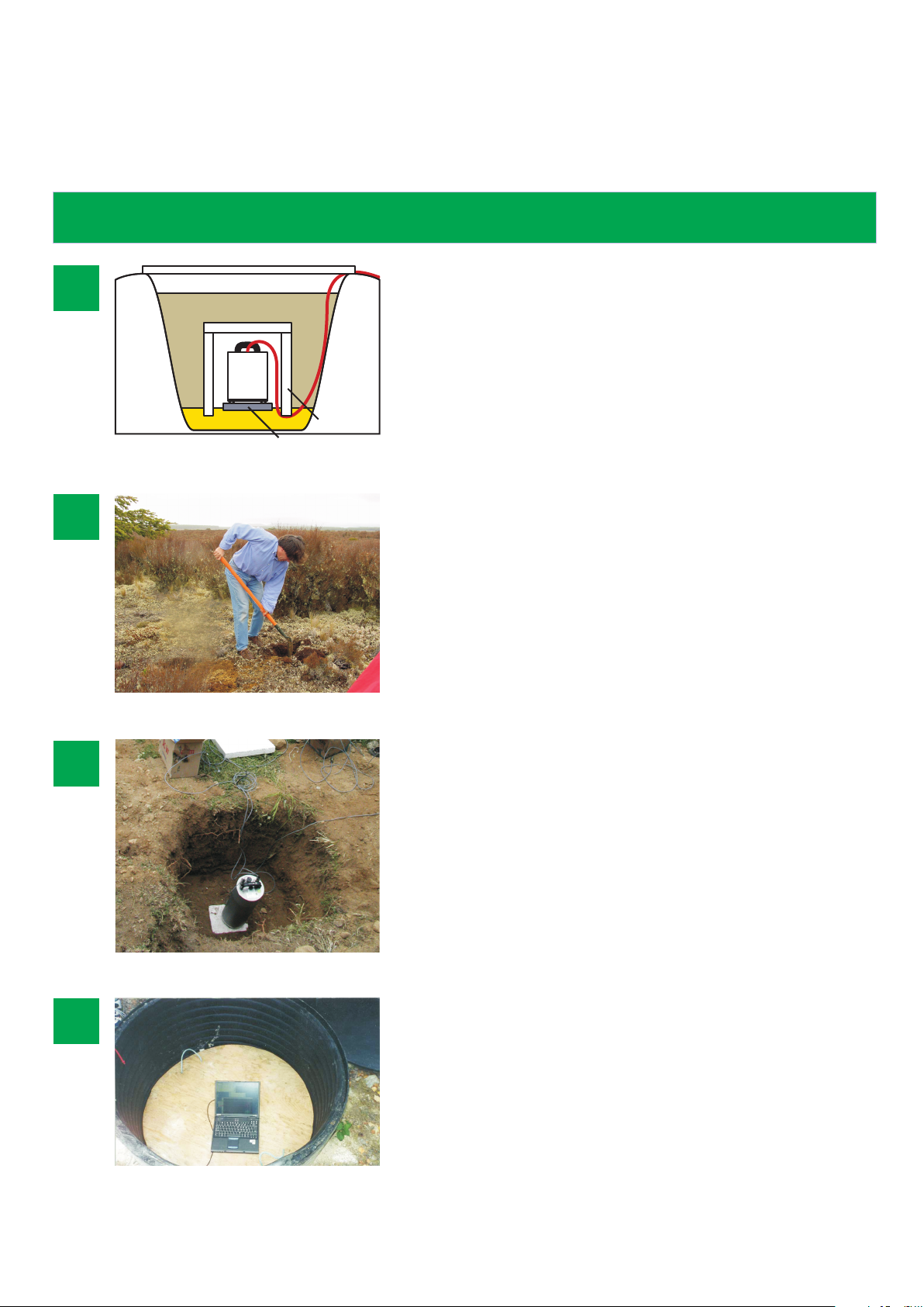
Installing in a pit or posthole
Signal cable
Cover
1
Check you have all necessary equipment, and select a
suitable location for the pit installation. You will need
2
3
Backfill
Dry sand
Sensor
Marble or
granite plinth
Polystyrene
shielding
- the sensor and other seismic equipment;
- an angle-grinder, if mounting on bedrock;
- otherwise, a supply of dry sand and a marble or
granite plinth for mounting the sensor;
- a protective shield of polystyrene or other suitable
material.
Dig a pit at least 60 cm deep at your chosen location, down
to the bedrock if possible.
On bedrock, use the angle-grinder to plane off part of the
surface. Clean the hole and go to the next step.
On compacted subsoil, pour a layer of fine sand over the
bottom of the hole, and mount the sensor on the granite
plinth on top of this sand layer.
Connect the sensor cables, and level and unlock the
components as described overleaf.
4
Check the system is working, and cover the sensor with its
protective shield.
If you are installing in a cased pit (as in this picture),
install the digitizer and power supply inside if possible, and
seal the installation with a weatherproof cover.
Otherwise, backfill over the shield with fresh soil. Mark the
sensor position, e.g. with its GPS unit. Install the recording
equipment and batteries, if used, in separate pits.
MSH-030-0001-A : Page 2 of 2
 Loading...