

Page 1

CMG-1T
OCEAN BOTTOM
SEISMOMETER
OPERATOR’S GUIDE
REVISIONS
ISSUE ECN DATE COMMENTS
A First 15.05.96
B 24.01.97 Add drawings and photos.
C 14.09.99 Addition of Appendix A
DESIGNED AND MANUFACTURED BY:
GÜRALP SYSTEMS LIMITED
3 MIDAS HOUSE
CALLEVA PARK
ALDERMASTON
READING
BERKS, RG7 8EA
ENGLAND
Telephone: +44 (0) 118 9819056 Fax: +44 (0) 118 9819943
Page 2

Page 3

Operator’s Guide CMG-1T Ocean Bottom
Seismometer
DESIGNED AND MANUFACTURED BY:
GÜRALP SYSTEMS LIMITED
3 MIDAS HOUSE
CALLEVA PARK
ALDERMASTON
READING
BERKS, RG7 8EA
ENGLAND
PROPRIETARY NOTICE
The information in this Manual is proprietary to Güralp Systems Limited and
may not be copied or distributed outside the approved recipient’s organisation
without the approval of Güralp Systems Limited.
Güralp Systems Limited shall not be liable for technical or editorial errors or
omissions made herein; nor for incidental or consequential damages resulting
from the furnishing, performance, or use of this material.
September, 1999, Issue C
Page 4

Page 5

Operator’s Guide CMG-1T Ocean Bottom
Seismometer
HOW THIS USER’S GUIDE IS ORGANISED
This user’s guide is sectionalised with each section dealing with a specific topic.
Generally speaking, background material and technical explanations are found in
the later sections, while practical instruction occurs at the beginning. A list of
tables and specifications are found at the end of the manual.
Each section of the user’s guide is kept, as nearly as possible, self-contained and
free-standing so that the sections can be read in any order. General crossreferences are provided where necessary, but complicated notation of the
sections and paragraphs is avoided.
A very brief description of the user guides sections are given below but the
contents page provides the titles of each section.
INTRODUCTION: This section summarises the CMG-1T sensor, the
levelling system and the micro-controller which controls
the sensors and the levelling system.
QUICK START: This section gives quick itemised procedures for
unpacking, installing and operating the CMG-1T. The
user can use this section to quickly deploy and
operate the instrument.
OPERATION: These sections make up the instructions to operate the
CMG-1T sensor, with detailed description of the sensor
and operation.
September, 1999, Issue C
Page 6

Page 7

Operator’s Guide CMG-1T Ocean Bottom
Seismometer
CONTENTS
SECTION
INTRODUCTION 1 Introduction
2 Description and Explanation of the
Mechanical Sensor System
3 Feedback System Description
4 Force Transducer
5 Levelling Platform
6 Levelling Platform Inclinometers
7 System Input/Output Signal Format
and Connections
8 Seismometer and Levelling Bowl
Control Commands
9 Mounting of the Levelling System
September, 1999, Issue C
Page 8

Page 9
Operator’s Guide CMG-1T Ocean Bottom
Seismometer
1. INTRODUCTION
The qualities of Güralp Systems Limited’s broadband sensors (Ref 1) clearly
opened up a new era in ocean bottom and ocean bottom borehole seismology.
A pilot experiment which deployed CMG-3 sensors (Refs 2 and 3) clearly
indicated some of the advantages that can be ascertained from broadband
sensors installed under water. The only disadvantage of CMG-3 as an ocean
bottom instrument is the sensor mass locking mechanism. While the CMG-3
locking mechanism is adequate for most , if not all, conventional installations,
due to increased reliability requirements, a new foolproof patented locking
mechanism has been designed. The CMG-1T sensor uses this unique mass
locking mechanism which virtually eliminates the possibility of sensor pivots or
springs being damaged.
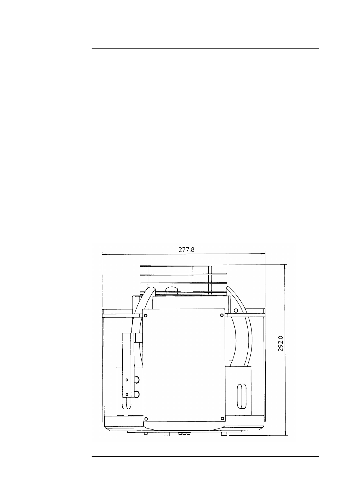
The CMG-1T OBS seismometer consists of three solid body CMG-1
seismometer components. The three component sensors are organised to be
orthogonal to each other. The base plate of the sensors is fixed to the bottom
plate of the levelling dish as shown in the following diagram. The analogue
electronics for the sensors are stacked above the sensors. The OBS analogue
electronics are specially designed to have low power consumption, and the
quiescent current consumption of the sensor system is 26 mAmps from a 12
Volts supply.
September, 1999, Issue C Section 1, Page 1
Page 10
CMG-1T Ocean Bottom Seismometer Operator’s
Guide
The levelling dish structure has ± 30 degrees of levelling capability, with an
accuracy of ± 0.2 degrees, and stability which is fit to be used as a levelling
platform for a broadband sensor.
Section 1, Page 2 September 1999,
Issue C
Page 11
Operator’s Guide CMG-1T Ocean Bottom
Seismometer
Individually each sensors outputs can be further zeroes within a range of ± 2.5
degrees. The horizontal sensors are levelled (or mass position output zeroed)
by tilting the sensor bases, in the case of the vertical sensor the sensor boom
position is controlled by the movement of the tip of the main load bearing
spring.
The sensor command functions are controlled with a single chip microcontroller, type H8 (Hitachi). The sensor function lock, unlock, centre and
levelling bowl functions are all initiated with command words instructed
through the system serial communication port.
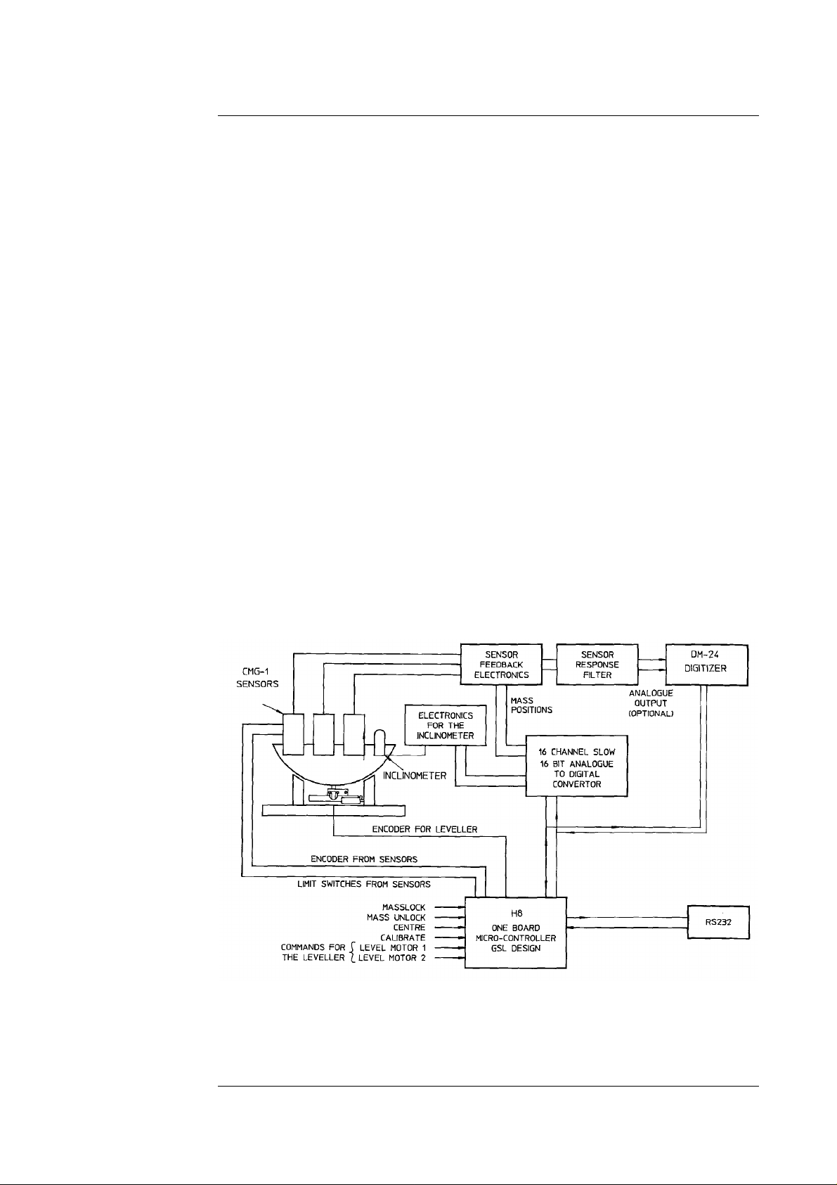
A two axis inclinometer is used to measure the tilt of the sensor levelling bowl
in the North/South and East/West directions. The inclinometer is interfaced to
the micro-controller which ensures levelling of the sensor levelling bowl with a
single English command “LEVEL”.
A two axis inclinometer is used to measure the tilt of the sensor base in the
North/South and East/West directions.
The commands to operate the seismometer control functions, the digitizers and
the data from the digitizers is communicated with a serial communication line.
In the case where an internal digitizer is used, the sensor outputs are digitized
with a 24-bit digitizer and the data packets are time stamped at the source. A
complete block diagram of the ocean bottom sensor is given below.
September, 1999, Issue C Section 1, Page 3
Page 12

CMG-1T Ocean Bottom Seismometer Operator’s
Guide
Ref 1:
Which Broad Band seismometer in Ocean Bottom Observatory?
Preliminary results of simultaneous recording of seismic signals using
STS-1, STS-2, CMG-3 during May 1993 at St Sauveur (FRANCE)
S. Cacho et al.
Ref 2:
The French Pilot experiment OFM/SISMOBS: First scientific results
on noise level and event detection
Jean-Paul Montagner et al.
Ref 3:
The Pilot experiment OFM/SISMOBS: A first step towards a
permanent oceanic geophysical observatory
J.P. Montagner et al.
Section 1, Page 4 September 1999,
Issue C
Page 13

Operator’s Guide CMG-1T Ocean Bottom
Seismometer
2. DESCRIPTION AND EXPLANATION OF THE MECHANICAL
SENSOR SYSTEM
A photograph of the overall construction and layout of the seismometer are
given here, together with some details of the individual sensors.
The horizontal and vertical sensors are based on a shared design, that of a leaf
spring suspended boom supporting a transducer coil, the boom and coil forming
the inertial mass. The boom consists of a solid machined beam which swings on
a frictionless hinge. The system has no spurious resonances below 140 Hz. The
vertical component instrument has a pre-stressed triangular support spring
which supports the weight of the mass. The horizontal component sensors have
un-stressed flat triangular springs, giving a natural period of about 1 second,
while the vertical component sensor has a natural period of about 0.5 second.
The effective mass is about 250g in each case. The small stiff springs and short
boom lead to a very compact design permitting the designer to incorporate three
instrument in a relatively compact case.
September, 1999, Issue C Section 2,
Page 1
Page 14

CMG-1T Ocean Bottom Seismometer Operator’s
Guide
The adjustments required for operation consist of levelling the boom of the
vertical sensor and tilting the bases of the horizontal sensors to centre the
movements in their equilibrium positions. These adjustments are made by small
DC motors operating through gear trains to tilt the bases of the horizontal
sensors and to apply a small extra force to the vertical sensor’s boom.
For transportation the masses have to be locked securely in their frames, taking
the strain off the support hinges. The locking is performed by a small motor
driven clamp in response to a control command.
Section 2, Page 2 September 1999,
Issue C
Page 15

Operator’s Guide CMG-1T Ocean Bottom
Seismometer
The positions of the masses of all sensors are monitored by identical
capacitative position sensors and it is the signals from these which form the
basis of the seismometers’ mode of operation. The electronic processing of the
mass position signals is carried out on circuit boards mounted in a screened
compartment above the mechanical components. The main output voltages,
proportional to ground-velocity, are transmitted out of the case on differential
balanced lines, while the mass position signals are sent as single-ended circuits
referred to analogue ground via the output plug. Coming into the case are the
control signals which signal the control circuit to clamp or unclamp the masses
and to start the levelling and zeroing sequences, running the motors to null the
offset voltages from the transducers. There is also provision for applying a
calibrating voltage to the force transducers to allow the deflection sensitivity to
be measured.
The outer case is completely hermetically-sealed to the base by a compression
‘O’ ring joint and all electrical connections pass to the exterior via a glass sealed
plug. The only mechanical adjustments on the case are the three levelling feet
which can be locked in position without disturbing the setting. The tips of the
feet carry insulating beads which prevent electrical ground loops from being set
up inadvertently.
September, 1999, Issue C Section 2,
Page 3
Page 16

Page 17

Operator’s Guide CMG-1T Ocean Bottom
Seismometer
3. THE FEEDBACK SYSTEM DESCRIPTION
In a practical broadband seismometer the natural characteristics of the
seismometer are never used. The period and damping of the sensor is
completely determined by a feedback loop which supplies a counter-force to the
inertial mass sufficient to oppose any overall motion. The force required to
restrain the movement of the mass is then a measure of the inertial force exerted
by the mass due to the ground motion.
The feedback control operates as described below:
The capacitative position sensor provides a voltage proportional to the
displacement of the mass from its equilibrium position. This voltage, after
amplification, generates a current in the force transducer coil which tends to
force the mass back to its equilibrium position. With a high loop gain the
motion of the mass is effectively cancelled thus providing the force balance
condition. The feedback voltage is then a measure of the force and thus of the
acceleration applied to the mass.
In order to obtain stable operation over the whole frequency range the feedback
loop phase shift has to be carefully controlled. This is achieved by
compensation components in the forward and feedback paths as shown in the
following block diagrams.
The CMG-1T sensor is supplied with one of two different types of feedback
system. The main difference between the two systems is in the feedback
electronics used to implement the required responses. In the HYBRID circuit
the feedback components between the output signal and the seismometer mass
consist only of a single capacitor in parallel with a resistor. This results in only
a single pole at the specified frequency. The output of the seismometer at
frequencies below this frequency is proportional to ground acceleration. This
contrasts with the CONVENTIONAL RESPONSE feedback system which has
an additional parallel feedback circuit consisting of a non-inverting integrator in
series with a resistor. The response of the arrangement gives a double pole at
the specific frequencies. In all cases, signal in frequency bands longer than the
specified velocity corner frequencies (eg. 10 sec, 30 sec, 100 sec and 360 sec.)
can be recorded using the mass position outputs. However, high pass circuitry
is recommended to remove the sensor output offsets.
September, 1999, Issue C Section 3,
Page 1
Page 18

CMG-1T Ocean Bottom Seismometer Operator’s
Guide
100 SEC AND 30 SEC HYBRID VELOCITY SENSOR
The block diagram for both of the hybrid systems is given below.
In comparison to a conventional feedback accelerometer the hybrid velocity
response is obtained with a dominant single pole which is set at either 0.1 Hz or
at 0.033 Hz. The dominant pole breaks the system response into two sections,
the first one being flat to acceleration from dc to the dominant corner frequency
(0.1 Hz or 0.033 Hz) and the second response flat to velocity starting from the
dominant corner frequency until the high frequency cut off.
The high frequency cut off is realised with an active low pass filter. Without
this low pass filter the sensor velocity response is flat up to 100 Hz.
As the hybrid system is dc coupled to remove any dc offsets a 0.01 Hz (100 sec)
or 0.005 Hz (200 sec) active high pass filters are used. These filters are external
to the sensor feedback loop.
The main advantage of such a system is to provide a stable response,
particularly for portable systems, with a high saturation level at high frequencies
and high dynamic range at the long periods.
Section 3, Page 2 September, 1999,
Issue C
Page 19

Operator’s Guide CMG-1T Ocean Bottom
Seismometer
30 SEC, 100 SEC AND 360 SEC VELOCITY SENSOR
The block diagram of the velocity responsive seismometer is given below. This
block diagram is applicable to all the three types of velocity sensors.
The system velocity responses are defined by a transfer function identical to that
of a conventional long period sensor with a velocity transducer whose natural
resonant frequency is set at 0.033 Hz, 0.01 Hz or 0.0027 Hz and the damping z
at 0.707.
Similar to that of the hybrid system, the high frequency portion of the sensor
response is determined with a low pass filter. The corner frequency of this low
pass filter is specified by the user.
An output proportional to the ground acceleration is available from either of the
above described sensor frequency responses. In a feedback seismometer with a
displacement transducer it is essential to monitor the acceleration output as the
position of the displacement transducer is provided by this output. Under
normal operating conditions the displacement transducer needs to be in its
‘NULL’ ‘CENTRED’ or ‘ZERO’ position. The acceleration output (V/m/s2) is
also known as the sensor MASS POSITION as the displacement transducer is
always attached to the sensor inertial mass.
September, 1999, Issue C Section 3,
Page 3
Page 20

CMG-1T Ocean Bottom Seismometer Operator’s
Guide
The figures below gives the comparative response of a conventional velocity
output broadband sensor and hybrid output broadband sensor. The family of
curves shows the sensor output response to input acceleration in units of
V/m/s2. Curves 1, 2 and 3 are the conventional 360 sec, 100 sec and 30 sec
responses and curves 4 and 5 are the hybrid 10 sec and 30 sec responses.
Alternatively the system amplitude plots are given below as output against input
velocity.
Section 3, Page 4 September, 1999,
Issue C
Page 21

Operator’s Guide CMG-1T Ocean Bottom
Seismometer
4. THE FORCE TRANSDUCER
Force feedback seismometers which use a coil and magnet system to generate
the restoring feedback force are inherently dependent on the constancy of the
field strength produced in the force transducer. The design of the magnetic
circuit and the magnet/pole assembly is such that the field strength from the
feedback transducer is constant over large deflections and current levels.
Tests have shown that the mechanical suspension system and the electronics of
the CMG-3NSN is linear to better than 107 db (measured at ASL during USGS
National Network evaluation in 1989).
September, 1999, Issue C Section 4,
Page 1
Page 22

Page 23

Operator’s Guide CMG-1T Ocean Bottom
Seismometer
5. LEVELLING PLATFORM
The large three-component CMG-1T seismometer base is fitted inside a
levelling platform which is operated with 2 high torque dc motors.
The operating principle and the philosophy of the levelling platform is based on
the natural stability provided by the bell and socket type construction joint. The
three-component sensors are contained in a machined cavity inside a structure
that resembles an inverted dome whose exterior is machined to a spherical form.
The unit rests in a ring shaped bearing so that the dome can move freely in
azimuth and tilt directions.
A metal post, mounted centrally under the dome, carries a machined ball which
articulates with a cylindrical cavity in a driving block below it. The driving
block, moving on a plane surface below the dome effectively translates the
position of the dome expressed in spherical co-ordinates into positions on a
plane expressed in polar co-ordinates. The described position mechanism
consists of a turntable and a lead screw to drive the central block.
The described mechanism is more stable and more compact than the more usual
gimbal arrangement and also has fewer moving parts. For broadband OBS
seismometer applications the gimbal arrangement would not be sufficiently
stable.
The rotary motion of the bowl is provided by a worm-drive driven by a dc
motor. The tilt drive is provided by a 1 mm pitched lead screw which linearly
positions the bearing block on a pair of parallel slides. The lead screw is also
driven by a dc motor.
September, 1999, Issue C Section 5,
Page 1
Page 24

CMG-1T Ocean Bottom Seismometer Operator’s
Guide
The required method of zeroing the bowl tilt is provided diagrammatically in the
drawing below. The radial and azimuth adjustments are done until the 2 axes
inclinometer outputs are brought as close to zero as possible. The radial offset
tilt magnitude is calculated from the X, Y readings of the inclinometer and the
azimuth position is determined from the sign information of the inclinometers.
Two sets of position sensors fitted to the motor shafts transmit the digital shaft
position signals to a micro-processor to enable precise radial and azimuth
movement without slippage. In fact, the position detectors are absolute and
provide position information without losing information when the system is
switched off.
Section 5, Page 2 September, 1999,
Issue C
Page 25

Operator’s Guide CMG-1T Ocean Bottom
Seismometer
6. LEVELLING PLATFORM INCLINOMETERS
The ± 30° levelling bowl drawing is given. Within the levelling bowl a 2 axis
inclinometer is installed to provide the tilt of the bowl in two independent axes
over the complete tilt range of the levelling bowl. The inclinometer outputs are
not linearly related to the actual tilt but calibration information is provided to
the user to establish the tilt of the bowl with reasonable accuracy. In actual fact,
in this application, it is not required that the inclinometer output should be
linearly related to the bowl tilt.
The inclinometer output varies over a voltage range of ± 4 Volts and the output
impedance of the circuit is <10Ω. The average power consumption of the
inclinometer circuitry is kept as low as possible. Normally the digital microprocessor circuitry is used to switch the inclinometer electronics off after the
initial instrument installation. It is also accepted that it is unnecessary to re-use
the levelling bowl after initial setting up as the individual sensor components
themselves have ± 2.5° of levelling facility.
September, 1999, Issue C Section 6,
Page 1
Page 26

Page 27

Operator’s Guide CMG-1T Ocean Bottom
Seismometer
7. SYSTEM INPUT OUTPUT SIGNAL FORMAT AND
CONNECTIONS.
The seismometer system outputs consist of the following:
a) Velocity output.
b) Mass position outputs.
c) Control command serial input/output.
d) Calibration signal.
e) System power supply.
The pin assignments for the sensor systems 37-way D type connector are shown
in the photograph below.
Allocation of the pins is as follows:
20 V+ Velocity
23 V- Velocity
24 N+ Velocity
21 N- Velocity
22 E+ Velocity
25 E- Velocity
4 V Mass Position
5 N Mass Position
6 E Mass Position
8 Signal Ground
10 Calibration Signal
30 Calibration Enable
36 +Ve Sensor Power
Continued ..........
33 +Ve Bowl/SOH Power
September, 1999, Issue C Section 7,
Page 1
Page 28

CMG-1T Ocean Bottom Seismometer Operator’s
Guide
18 Sensor Power Return
14 Bowl/SOH Power Return
(also ground for RS232)
13 Transmit Data
32 Receive Data
The seismometer velocity outputs and mass position outputs operate over a
limited range of ± 4.4 Volts. This is due to the fact that the sensor electronics
are operated with ± 5 Volts supply. The output impedance of the analogue
output is set to be 94Ω.
The calibration document provides the sensor output responsivity, including the
sensor frequency response.
The sensor analogue electronics power supply voltage can be from 10 to 36
Volts. An isolated dc-dc converter is used to power the sensor analogue
electronics. The power consumption of the system under steady state condition
is 26 milli Amps from 12 Volts (0.32 Watts). This level of power consumption
is achieved without degradation in the sensor performance. However, during
locking, unlocking and centring operations, the power consumption will
increase substantially. To compensate for the large power fluctuations, internal
power management is provided. (The power management unit is under
development, 4th December, 1996.)
The sensor supply is completely separate from the bowl and levelling
electronics. Under normal conditions, the bowl and levelling electronics are
switched off immediately after installation.
The levelling and system status commands are described in the later sections.
In cases where the CMG-1T system is installed within a glass sphere, the sensor
outputs are limited due to the limited number of connector pins. The following
pin assignments must be used for the waterproof glass bowl connector.
1 V+ Vel
2 N+ Vel
3 E+ Vel
4 Sig Gnd
5 +V Sensor
6 0V Sensor/0V
Bowl/RS232 Gnd
7 +V Bowl
8 Tx Data
9 Rx Data
Section 8, Page 2 September, 1999,
Issue C
Page 29

Operator’s Guide CMG-1T Ocean Bottom
Seismometer
8. SEISMOMETER AND LEVELLING BOWL CONTROL
COMMANDS
The operation of the OBS system is carried out by a set of (English) command
words entered from a computer terminal connected to the system serial port.
The described commands control the operation of the OBS to lock the sensor
masses, unlock the sensor masses and centre the seismometers once the sensor
masses are unlocked.
Prior to unlocking the sensor masses the levelling bowl would be required to be
levelled after system installation. The bowl levelling commands are Datum,
level and, bowl-align.
All the commands consist of one or two words. With two word commands the
first word is the parameter (qualifier) for the second which is the actual
command to be executed.
SEISMOMETER COMMANDS
Three commands are available.
a) LOCK - initiates locking sequence.
b) UNLOCK - initiates the unlocking sequence.
c) CENTRE - initiates the mass centring sequence.
Each of these commands is preceded by a qualifier specifying the instrument to
operate on.
Z - specifies vertical, (Z) sensor
N/S - specifies north/south. horizontal sensor
E/W - specifies east/west horizontal sensor
ALL - all 3 sensors execute command.
Examples: Z unlock - unlocks vertical sensor
ALL unlock - unlocks all the sensors
ALL centre - centres all the sensors.
BOWL LEVELLING COMMANDS
DATUM - sets bowl tilt and rotate positions to origin. The origin is
described as no tilt and rotate datum posit ion parallel to X
axis.
LEVEL - returns the bowl to DATUM, after which automatically
levels the bowl to within ± 0.3 degrees. The range of
levelling is ± 30 degrees.
BOWL-ALIGN - This command can be used to correct small deviations
September, 1999, Issue C Section 8,
Page 1
Page 30

CMG-1T Ocean Bottom Seismometer Operator’s
Guide
AFTER initial levelling. This command tries to reduce the
accuracy of levelling better than ± 0.3 degrees. It can only
be issued after the LEVEL command.
STATUS COMMANDS
HELP - displays all commands and parameters that are available.
SENSOR
STATUS - reports the digitized mass position outputs of the sensors.
BOWL
STATUS - reports the tilt and rotate orientation of the bowl and the X
and Y inclinometer readings.
SYSTEM SERIAL PORT
The baud rate of the serial line is 19,200 Baud 8 data bits, 1 stop bit, no parity
and no handshake.
Section 8, Page 2 September, 1999,
Issue C
Page 31

Operator’s Guide CMG-1T Ocean Bottom
Seismometer
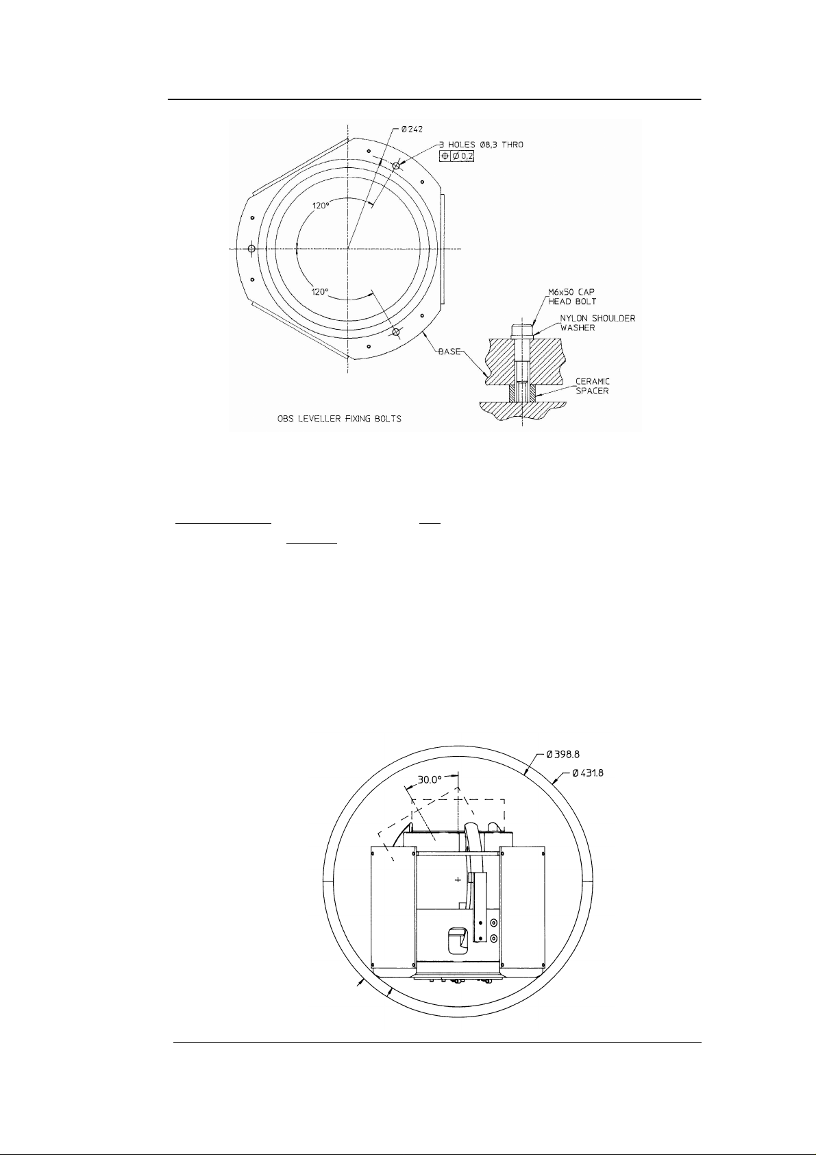
9. MOUNTING OF THE LEVELLING SYSTEM
Three fixing bolt positions are provided to fix the levelling system within a
pressure housing, as shown in the diagram.
The positions of the mounting holes are given in the following drawings
together with a suggested method of electrically isolating the levelling system
from it’s casing.
September, 1999, Issue C Section 9,
Page 1
Page 32
CMG-1T Ocean Bottom Seismometer Operator’s
Guide
It is recommended that ceramic spacers with nylon shoulder washers are used to
achieve a very high degree of insulation resistance, >>100MΩ.
IMPORTANT Care must be taken not to rest the levelling system on it’s base
without spacers as wiring which exists at the bottom of the
levelling system might be damaged.
The installation of the levelling system together with the sensor requires care
and precision. If the installation method within a casing is not completely
straight forward Güralp Systems Limited will be prepared to comment on your
particular design.
The levelling system can also be installed in a 17” glass sphere. A drawing of
the overall glass bowl and levelling system is given in the following diagram.
Section 9, Page 2 September 1999,
Issue C
Page 33

Operator’s Guide CMG-1T Ocean Bottom
Seismometer
Many methods can be used to restrain the movement of the levelling system
within the glass bowl. The preferred method used by us is given in the
following photographs.
A set of attachment points are glued to the inside of the glass sphere from which
semi-flexible linkages are used to attach the bottom of the levelling platform to
the glass sphere. Six separate holes are provided for such linkages.
September, 1999, Issue C Section 9,
Page 3
Page 34

CMG-1T Ocean Bottom Seismometer Operator’s
Guide
APPENDIX A
CMG-1T OBS User Connections
15 Way D Plug On
Function:
Power Board:
1 SOH +V Supply (10 to 36 Volts DC)
2 SOH 0V
3 Calibration Enable (Active Low)
4 Calibration Signal Input
5 Signal Ground
6 East / West Velocity Output
7 North / South Velocity Output
8 Vertical Velocity Output
9 Not Connected
10 RS232 Data Ground
11 RS232 Transmit From OBS
12 RS232 Receive To OBS
13 Not Connected
14 Instrument +V Supply (10 to 36 Volts DC)
15 Instrument 0V
Section 9, Page 4 September 1999,
Issue C
 Loading...