

Page 1

CD1.1 Tools for
CMG-EAMs
and CMG-DCMs with
Platinum firmware
Operator's Guide
Part No. MAN-EAM-1100
Designed and manufactured by
Güralp Systems Limited
3 Midas House, Calleva Park
Aldermaston RG7 8EA
England
Proprietary Notice: The information in this
manual is proprietary to Güralp Systems Limited
and may not be copied or distributed outside the
approved recipient's organisation without the
approval of Güralp Systems Limited. Güralp
Systems Limited shall not be liable for technical
or editorial errors or omissions made herein, nor
for incidental or consequential damages resulting
from the furnishing, performance, or usage of this
material.
Issue C 2010-06-15
Page 2

CD1.1 Tools for Platinum
Table of Contents
1 Introduction...........................................................................5
1.1 Platinum architecture.........................................................................5
1.2 CD1.1 architecture.............................................................................6
2 The CD1.1 modules.................................................................8
2.1 The CD1.1 multiplexor (data-mux-cd11)............................................8
2.1.1 Frame assembly time-outs..........................................................9
2.2 The GDI to CD1.1 converter (gdi2cd11)...........................................11
2.2.1 Channel Subframe Status Field.................................................12
2.3 The CD1.1 receiver (data-in-cd11)...................................................15
2.4 The CD1.1 sender (data-out-cd11)..................................................16
3 Typical configurations...........................................................18
3.1 Single seismic station......................................................................18
3.2 Central station of an array...............................................................19
3.3 Handling different frame lengths.....................................................19
3.4 Different frame lengths from one CMG-DM24..................................20
4 Using the Multiplexor............................................................ 21
4.1 Creating a new multiplexor instance...............................................21
4.2 Configuration options for the multiplexor........................................22
4.2.1 Configurable parameters in standard mode..............................22
4.2.2 Configurable parameters in expert mode..................................23
5 Using the GDI to CD1.1 converter...........................................25
5.1 Creating a new GDI to CD1.1 converter instance............................25
5.2 Configuration options for the converter...........................................26
5.2.1 Configurable parameters in standard mode..............................26
5.2.2 Configurable parameters in expert mode..................................31
6 Using the CD1.1 Receiver......................................................33
6.1 Creating a new CD1.1 receiver instance..........................................33
6.2 Configuration options for the receiver.............................................34
6.2.1 Configurable parameters in standard mode..............................34
6.2.2 Configurable parameters in expert mode..................................36
6.3 Operation notes...............................................................................37
2 Issue C
Page 3

Operator's Guide
7 Using the CD1.1 Sender.........................................................38
7.1 Back-filling and retransmission........................................................38
7.2 Creating a new CD1.1 sender instance............................................39
7.3 Configuration options for the sender...............................................40
7.3.1 Configurable parameters in standard mode..............................40
7.3.2 Configurable parameters in expert mode..................................44
8 Frame database files.............................................................45
8.1 Managing database files..................................................................45
8.2 Examining database files.................................................................47
9 Logging and analysing..........................................................48
9.1 Web-based tools..............................................................................48
9.1.1 Multiplexer log analysis tool......................................................48
9.1.2 Receiver log analysis tool..........................................................51
9.1.3 Sender log analysis tool.............................................................52
9.2 Command-line tools.........................................................................56
9.2.1 cd11-backfilldb-tool...................................................................57
9.2.2 cd11-framedb-tool.....................................................................59
9.2.3 cd11-timedb-tool.......................................................................60
9.2.4 cd11-frame-analyser-tool..........................................................62
9.2.5 cd11-management-tool.............................................................64
10 Authentication Management................................................67
10.1 Process Overview...........................................................................67
10.2 Spyrus Lynks operation..................................................................68
10.2.1 Card initialisation.....................................................................68
10.2.2 Keypair generation..................................................................68
10.2.3 Certificate signing requests.....................................................69
10.3 CD1.1 operation.............................................................................69
10.3.1 cd11-spyrus-tool.sh.................................................................70
11 Configuring DM24s and CD24s.............................................72
11.1 SoH reporting.................................................................................72
11.2 Latency..........................................................................................73
12 Calibration Values...............................................................74
12.1 Seismic sensors (velocity)..............................................................75
12.2 Seismic sensors (acceleration)......................................................76
12.3 Acoustic or infrasound sensors......................................................77
12.4 Wind speed....................................................................................77
12.5 Wind direction................................................................................77
June 2010 3
Page 4

CD1.1 Tools for Platinum
12.6 Temperature..................................................................................78
13 Optional flash memory........................................................79
14 File reference.....................................................................80
14.1 Operation.......................................................................................80
14.2 Database........................................................................................80
14.3 Inter-process communication.........................................................81
14.4 Configuration.................................................................................81
14.5 Run Control....................................................................................82
14.6 Miscellaneous................................................................................83
15 Revision history..................................................................84
4 Issue C
Page 5

Operator's Guide
1 Introduction
The Güralp CD1.1 tool suite for the Platinum firmware of CMGEAM, CMG-DCM and CMG-NAM hardware consists of four
modular components that can be used together to implement
either a single-station CD1.1 sender or a cross-array sender,
coalescing subframes from multiple stations into a single
outgoing data frame for the entire array.
When building an array, each individual element of the array is
actually a fully independent CD1.1 sender in its own right.
Supported features include fully-conformant status fields (State
of Health or SoH), flexible tamper line support, Canadian
compression and optional hardware authentication. Back-fill
capacity is limited only by the size of the fitted flash module or
disk array.
The CD1.1 tool suite runs in parallel to other programs, so it is
possible to use other data formats simultaneously.
1.1 Platinum architecture
Platinum firmware runs natively on CMG-EAMs and CMG-NAMs.
It can also be installed on the earlier CMG-DCM units. Platinum
firmware is based on the Linux operating system, which
provides a robust, familiar and flexible platform for the
protocol-handling and configuration software.
Seismic protocols are handled by a number of configurable
software modules, which run as user-space programs. They
can, on the whole, be stopped, reconfigured and started
independently of each other. The whole system is managed by
a flexible and extensible configuration interface which is
accessible in near-identical format from either the web
interface or a character-based terminal, connected either
serially or over a network.
The majority of the protocol-handling features of Platinum are
based on Güralp Data Interconnect, or GDI. The gdi-base
module serves as the central data interchange, accepting data
from a wide variety of input protocol-conversion modules,
buffering and re-ordering incoming data where necessary,
associating samples with their meta-data and providing data
via a consistent interface to the output protocol-conversion
modules.
June 2010 5
Page 6

CD1.1 Tools for Platinum
It is possible to use CD1.1 under Platinum without using GDI
but, if any data received in different formats are to be
converted to CD1.1, they will first be converted to GDI and
passed via the gdi-base module.
For pure CD1.1 implementations, it is neither efficient nor
necessary to convert to and from GDI, so a separate CD1.1
multiplexor module is provided. Incoming CD1.1 frames are
not passed to GDI, so it is not possible to convert them into
non-CD1.1 formats, such as SEEDlink.
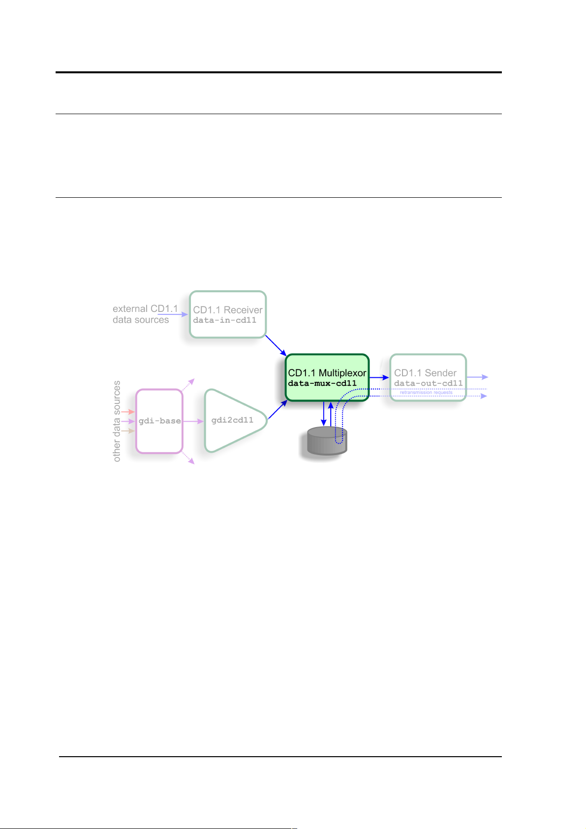
1.2 CD1.1 architecture
The CD1.1 tool suite consists of four modules:
• The CD1.1 receiver (data-in-cd11), which receives
data in CD1.1. format from external CD1.1 data
producers (DPs);
• The GDI to CD1.1 converter (gdi2cd11), which receives
data from GDI and, thus, indirectly, from any other
source in any supported format;
• The CD1.1 multiplexer (data-mux-cd11), which accepts
and combines data from one or more instances of the
previous two modules; and
• The CD1.1 sender (data-out-cd11), which takes data
from a CD1.1 multiplexer instance and transmits them
in CD1.1 format to external CD1.1 data consumers
(DCs).
Any useful configuration will, therefore, use at least three of
these modules. It is possible to configure more than one
instance of any of these modules and these can be connected
together as necessary when building more complex
implementations.
6 Issue C
Page 7

Operator's Guide
The diagram, above, shows a simple configuration using all four
CD1.1 modules. It is necessary to use either the CD1.1
Receiver (data-in-cd11) or the GDI to CD1.1 converter
(gdi2cd11) but not you do not need to use both.
The diagram also shows the subframe database which stores
all subframes passing through. These can then be used to
satisfy back-fill requirements and retransmission requests from
external receivers. This database can be located either in flash
RAM or on a hard drive, depending on considerations of storage
space and power consumption.
The data paths between modules are implemented using POSIX
local IPC sockets.
The following sections provide an introduction to how each
module works. Typical configurations will then be discussed,
followed by a detailed description of each module's
instantiation, configuration and use.
June 2010 7
Page 8
CD1.1 Tools for Platinum
2 The CD1.1 modules
This section of the manual will describe the function of each of
the four CD1.1 modules in detail. For precise configuration
instructions, please refer to sections 4 through 7.
2.1 The CD1.1 multiplexor (data-mux-cd11)
This is the central store-and-forward module for CD1.1
subframes. Every CD1.1 configuration requires at least one
CD1.1 multiplexor instance to be active. An instance of this
module must be configured before the configuration system
will allow any other CD1.1 modules to be instantiated.
CD1.1 subframes originating from either external CD1.1
sources (via data-in-cd11) or from non-CD1.1 sources (via
gdi2cd11) are transmitted to this module. The multiplexor
stores these subframes, either on disk or in flash RAM, and will
coalesces frames from multiple sources where this is
appropriate. It then forwards complete data frames onwards to
the output stage, data-out-cd11.
Subframes are stored briefly before they are assembled into
frames. There is a trade-off between the data latency - the
amount of time between a subframe's reception and its
transmission as part of a frame - and the overall framing
efficiency - the number of subframes that can be packed into a
single frame. A parametrised algorithm is used to allow the
operator to tune this to suit each application's specific
requirements - see section 2.1.1 on page 9 for more details.
8 Issue C
Page 9

Operator's Guide
The multiplexor is responsible for responding to retransmission
requests arriving from external receivers via a data-out-cd11
instance. The subframe store is used to satisfy these requests.
An interactive logging tool is provided to allow the operator to
query and inspect the contents of the store.
One storage file is created per day. To limit the amount of
back-fill being stored, a directory cleaner task must be set up
to remove unwanted storage files.
2.1.1 Frame assembly time-outs
Two separate time-out parameters are used to control the
assembly of related subframes into frames: one for real-time
data and one for back-filled data.
In complex networks, data may arrive from a number of CD1.1
data producers (DPs) along diverse routes, each with different
transmission latencies. DPs may be added and removed at any
time and communications may be interrupted for short or long
periods. A dropped link or a decommissioned station should
not interrupt the flow of data from other stations. Because of
this, the frame assembly algorithm does not and, indeed,
cannot know how many subframes it should expect for any
given time-stamp. It is therefore necessary to use time-outs
when assembling subframes into frames.
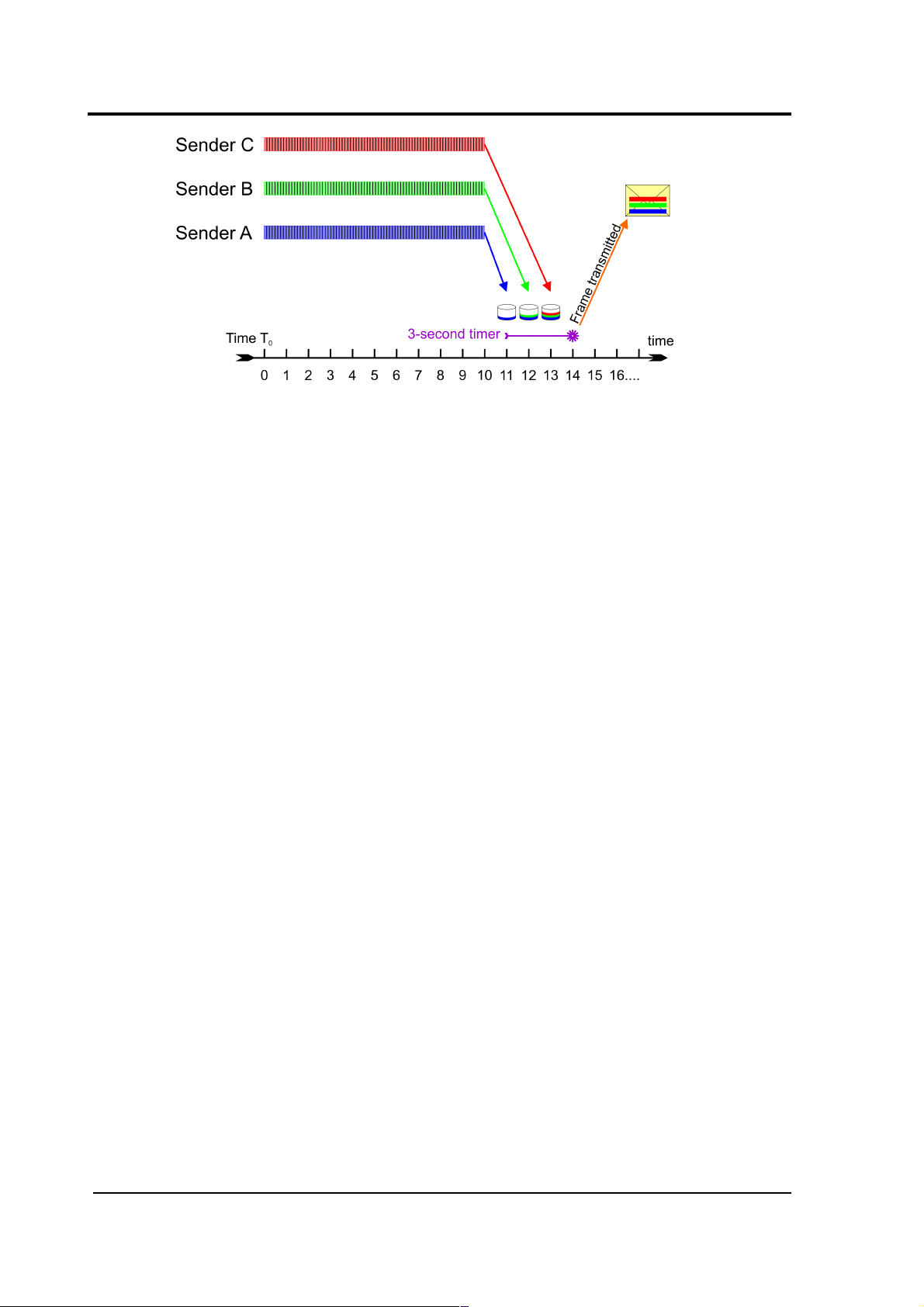
As an example, let us consider a hypothetical array with three
remote sensor stations functioning as CD1.1 DPs, all of which
use ten-second subframes, and a central data consolidation
station. The transmission times of the three links to the central
station are, say, one, two and three seconds. The real-time
data time-out at the central station will be set to three seconds.
At some time, T0, each station begins assembling samples into
subframes and, at around T0 + 10 seconds, they all transmit
their completed subframes to the station. Each subframe is
labelled with the time-stamp of its first sample: T0.
June 2010 9
Page 10
CD1.1 Tools for Platinum
At T0 + 11 seconds, the first subframe arrives at the station.
The multiplexer inspects the time-stamp and, as it has not seen
any subframes labelled T0 before, it stores the subframe in a
new collection, labelled T0, and sets an alarm (specific to this
collection) for the current time (T0 + 11) plus the time-out - i.e.
T0 + 14 seconds.
At T0 + 12 seconds, the second subframe arrives at the
station. The multiplexer inspects the time-stamp and places
the subframe in the existing T0 collection. At T0 + 13 seconds,
the third subframe arrives and is treated identically. At this
point, the multiplexer does not know that it has received all the
subframes, so it carries on waiting.
At T0 + 14 seconds, the alarm for this collection fires and the
multiplexer assembles all the subframes from the T0 collection
into a frame and passes it to the data-out-cd11 module(s).
The collection is moved to the data store and is no longer
considered active.
Now consider the case where the third communication link is
interrupted for, say, five seconds, starting at T0 + 10. The first
and second subframes will arrive as before and, at T0 + 14
seconds, they will be assembled into a frame and transmitted.
10 Issue C
Page 11

Operator's Guide
One second later, at T0 + 15 seconds, the link is restored and
the third subframe is transmitted. It will arrive at T0 + 18
seconds. The multiplexer inspects the time-stamp and, as it
has no longer has an active collection labelled T0, it stores the
subframe in a new collection, also labelled T0, and sets an
alarm (specific to this collection) for the current time (T0 + 18
seconds) plus the time-out - i.e. T0 + 21 seconds. No more
packets labelled T0 will arrive so, when the alarm fires, the lone
subframe will be wrapped up as a frame and transmitted on its
own.
If the time-out had been set to eight seconds, the delayed
subframe would have arrived in time to be sent along with the
other two: the packing efficiency would have been improved
but, as the completed frame would not have been transmitted
until T0 + 19 seconds, the overall latency would have
increased. The time-out should thus be adjusted to achieve the
desired trade-off between subframe packing efficiency and
overall data latency.
Where back-filled subframes are involved, it is assumed that
latency is of lesser concern - the data are already significantly
delayed - and packing efficiency is considered more important.
For this reason, although the algorithm is identical, a
separately configurable time-out is provided which only applies
to back-fill frames. It is expected that this time-out will
normally be set to a significantly higher value than the live
data time-out.
2.2 The GDI to CD1.1 converter (gdi2cd11)
This module is used to encode data from non-CD1.1 sources
into standards-compliant CD1.1 subframes. It should be used,
for example, when data from directly attached digitisers and
digital instruments is to be transmitted using CD1.1.
June 2010 11
Page 12
CD1.1 Tools for Platinum
The subframes contain a number of additional data beside the
samples:
• Channel meta-data is used to populate the “instrument
type” and “gain” fields
• The “channel status” field is populated using
information from the state-of-health data provided by
gdi-base, from the anti-tamper lines (and other digital
input/output fields) and from the internal temperature
and voltage monitoring subsystems.
• Optionally, a cryptographic signature generated by a
hardware engine (such as the Spyrus encryption card).
Operation of such hardware is discussed in chapter 10
on page 67.
The subframes can support any sample rate and can be of
various durations (in multiples of 10 seconds).
2.2.1 Channel Subframe Status Field
The gdi2cd11 module implements the first permitted status
field as defined with format value = 1 in the CTBTO standard
revision 0.2. There are several reserved bits and bytes in the
standard, and these can optionally be mapped to additional
details in the gdi2cd11 configuration (see section 6.2.1 on page
34).
The meaning of the bits is mapped as follows (counting from 1,
with 1 being the least significant bit and 8 the most):
12 Issue C
Page 13

Operator's Guide
Byte(s) Bit(s) Description Mapping
2 1 Dead sensor channel Not used
2 Zeroed data Not used
3 Clipped Not used
4 Calibration underway Set when calibration is in
progress on associated
component
3 1 Equipment housing open Configurable tamper monitor
2 Digitiser open Configurable tamper monitor
3 Vault door opened Configurable tamper monitor
4 Authentication seal
broken
Configurable tamper monitor
5 Equipment moved Configurable tamper monitor
6–8 Future use Configurable tamper monitors
4 1 Clock diff. too large Set if clock difference
≥±1000µs (configurable)
2 GPS receiver off Set if ADC module reports no
communication from GPS, or
GPS power is off
3 GPS receiver unlocked Set if ADC module reports
clock is not phase locked to
GPS PPS signal
4 Analog input shorted Not used
5 Calibration loop back Not used
6–8 Future use Not used
5 1 Main power failure Configurable; set if voltage of
chosen line drops below
specified value
2 Backup power unstable Configurable; set if voltage of
chosen line drops below
specified value (independent
from main power failure bit)
3–8 Future use Not used
6 1–8 Undefined Configurable; 8-bit voltage,
temperature, power or
current reading #1
7 1–8 Undefined Configurable; 8-bit voltage,
temperature, power or
June 2010 13
Page 14

CD1.1 Tools for Platinum
Byte(s) Bit(s) Description Mapping
current reading #2
8 1–8 Undefined Configurable; 8-bit voltage,
temperature, power or
current reading #3
9–28 Time of last GPS
synchronisation
Most recent reported lock
from ADC module, invalid (<
year 2000) if never locked.
29–32 Clock differential in
microseconds
If clock is locked, this is the
measured difference between
the ADC's sample clock and
the GPS PPS line in µs. If
unlocked, it is an estimate
(magnitude, so always
positive) of the drift based on
the measured worst-case drift
of the ADC's crystal.
Bytes 6, 7 and 8 of the status field can optionally be used to
monitor line voltage, power or current flow, or temperature. As
there are only 8 bits available, the scales for the value are
complex and must be manually configured by the operator in
order to get the best range available. Values that are outside
what can be represented are clipped at 0 or 255 (not aliased).
The voltage scale allows a value between 5.0 and 30.5 to be
represented with 0.1 increments. To convert from the unsigned
byte value x to an analog value, use:
y=5.0x ×0.1
The power or temperature scale allows a value between -64
and 63.5 to be represented with 0.5 increments. Note CMGEAM modules measure incoming power as positive, and
outgoing power as negative. To convert from the signed byte
value x to an analog value, use:
y=x ×0.5
To convert from the unsigned byte value u to an analog value,
use:
u128 : y=u × 0.5
u≥ 128 y =u−256 × 0.5
14 Issue C
Page 15

Operator's Guide
The current scale allows a value between -1.28 and 1.27 to be
represented with 0.01 increments. Note CMG-EAM modules
measure incoming current as positive, and outgoing current as
negative. To convert from the signed byte value x to an analog
value, use:
y=x ×0.01
To convert from the unsigned byte value u to an analog value,
use:
u128 : y=u × 0.01
u≥ 128 y =u−256 × 0.01
2.3 The CD1.1 receiver (data-in-cd11)
This module receives CD1.1 frames from external CD1.1
senders (DPs). It is typically used at an array data centre,
where it receives data frames from any CD1.1 senders in the
array; typically each array element or station will have its own
CD1.1 sender.
The receiver is fully standards-compliant, although it has no
support for validating incoming signatures.
The receiver can accept connections and data from multiple,
simultaneous, remote DPs. It correctly identifies and requests
re-transmission of missing data frames by issuing CD1.1
acknack frames.
June 2010 15
Page 16

CD1.1 Tools for Platinum
Note: Unlike other Platinum data reception modules, the CD1.1
receiver module does not currently alter or decode any
subframes it receives and it does not pass them to gdi-base:
they are passed on verbatim and only to the multiplexor
module.
2.4 The CD1.1 sender (data-out-cd11)
This module is a fully standards-compliant CD1.1 sender (DP).
It is responsible for:
• Receiving CD1.1 channel subframes from the
multiplexor;
• Assembling them into full CD1.1 frames;
• Transmitting them over a TCP network to a remote
receiver (DC);
• Handling retransmission requests originating from its
clients;
• Monitoring the transmission log to determine whether
any gaps have occurred (for example, due to restarting of the sender process) and, if so, transmitting
the missing packets (back-fill);
• Logging all transmissions to a “frame list” held on local
disk or Flash memory; and, optionally,
• Digitally signing the frames using an optional hardware
encryption engine (see chapter 10 on page 67).
16 Issue C
Page 17

Operator's Guide
A CD1.1 sender module can only transmit to a single Data
Consumer (DC). If there is a requirement to support multiple
DCs, multiple sender module instances are needed. Each can
send a different set of subframes, if required.
Because the multiplexer supports multiple senders, it is more
efficient for the multiplexer to store transmitted frames, rather
than the sender. This avoids having to store the same frame
multiple times. However, because the frame numbering of
outgoing frames is connection specific, the multiplexer cannot
know these numbers and it stores frames by time-stamp,
rather than by frame number. The sender keeps track of which
frame is which by storing a database of frame numbers against
timestamps. This database is consulted when the sender
receives an acknack frame, so that it can request the correct
frame from the multiplexer by time-stamp.
It also handles back-fill over extended periods of outage by
recording which times the system was down, and requesting
the data once the link is established again. Back-fill order is
configurable: it can either be “first-in, first-out” (FIFO) or “lastin, first-out” (LIFO).
June 2010 17
Page 18

CD1.1 Tools for Platinum
3 Typical configurations
Some typical scenarios, with the associated module set-ups,
are shown in the following diagrams.
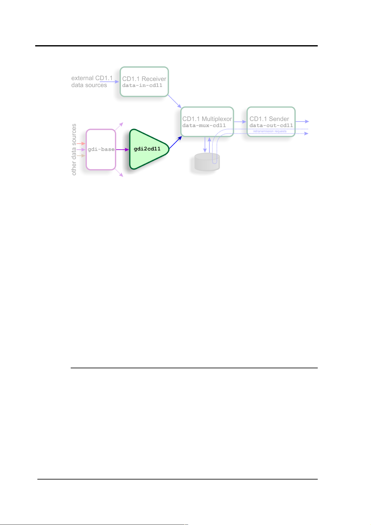
3.1 Single seismic station
In this scenario, one or more analogue sensors are digitised by
a CMG-DM24, the output from which is fed over a serial or
network link to a CMG-EAM. The data are passed to gdi-base
in the normal way and the gdi2cd11 module combines them
with state-of-health and other meta-data to form CD1.1
subframes. These are passed to the multiplexor, which
assembles them into frames for onward transmission by the
CD1.1 sender.
18 Issue C
Page 19

Operator's Guide
3.2 Central station of an array
The second diagram illustrates a typical array scenario, where
the central CMG-EAM accepts full CD1.1 frames from each
element and coalesces them, outputting only a single station
frame.
3.3 Handling different frame lengths
June 2010 19
Page 20

CD1.1 Tools for Platinum
This diagram depicts the use of two gdi2cd11 converter
modules to handle subframes with different frame lengths.
The multiplexor combines them into a single CD1.1
transmission. Although all the data passes through the gdi-
base module, input filtering in the gdi2cd11 instances
separates them again so that each can be framed
appropriately.
3.4 Different frame lengths from one CMG-DM24
The diagram above shows another way to handle different
frame lengths. In this scenario, two sensors of different types
are connected to the same CMG-DM24 digitiser and their
outputs travel together as far as the gdi-base module. Two
separate gdi2cd11 modules are then used to implement the
different subframe durations, according to the sensor type.
The outputs from the converters are then recombined by the
multiplexer module and passed to a common sender.
20 Issue C
Page 21

Operator's Guide
4 Using the Multiplexor
The multiplexor module has two main functions: Firstly, it acts
as an IPC connection point between the input and output
modules, allowing an arbitrary number of modules of either
type to be connected together; Secondly, it stores subframes
on disk, allowing them to be retrieved by output modules for
back-fill and retransmission purposes.
In most applications, only a single multiplexor instance is
required although, if you have two completely independent
data paths, it may make sense to use more than one
multiplexor. Note that each input and/or output module can
only ever be connected to a single multiplexor instance.
4.1 Creating a new multiplexor instance
In the web interface, select “Configuration -> Services” from
the left-hand menu or from the command line, run
gconfig
and then select “System services”.
Now choose “data-mux-cd11 -- CD1.1 multiplexor” to view a list
of configured multiplexor instances. You can choose to either
configure any existing instance (as described in the following
section) or select “Create new service instance” to create a
new one.
A form is displayed which allows you to set various parameters
for the instance. The default values are suitable for most
applications but each parameter is discussed in the following
section. After entering the desired configuration for the
instance, choose Submit.
This will create (if it is new) and configure the multiplexor
instance. If it is not already running, you can start it by using
“Control -> Services” on the web menu or by running
/etc/init.local/data-mux-cd11.0 start
from the command line.
June 2010 21
Page 22

CD1.1 Tools for Platinum
The zero after the period in the command name determines
which multiplexor instance is to be started, so the command to
start a second instance would be
/etc/init.local/data-mux-cd11.1 start
4.2 Configuration options for the multiplexor
There are two levels of configuration options available:
standard and expert. The configuration screen is first displayed
in standard mode but extra options can be displayed by
clicking the “Expert” button at the bottom of the form.
4.2.1 Configurable parameters in standard mode
The User description is an alternative, human-readable label
for this instance. It is used, for example, in log files. If you are
building a complex application with several multiplexers, you
should set this to something which describes the function of
this particular instance. In most cases, this can be left at the
default setting.
22 Issue C
Page 23

Operator's Guide
The Enable check-box controls whether this instance is to be
automatically started each time the system boots or whether it
should be left to be started manually.
The Delete check-box, if ticked, will cause this instance to be
deleted when the form is submitted.
The Database directory field allows you to specify the path to
a directory where the subframes are stored. A directory
specified here should not be used for any other purposes and
should not be shared with any other data-mux-cd11 instances.
The default location, /var/lib/data-mux-cd11.n, where n is
the instance identifier, will be adequate in most applications.
Note that large files will accumulate in this directory so: (a) you
should ensure that you have sufficient space available to store
the expected amount of data; and (b) you should configure a
directory cleaner to remove unwanted files from this directory
(see Section 8.1 on page 45 for more details). This database
may be stored on additional flash memory, if fitted: See
Section 13 on page 79 for more details.
The Data frame transmission period field controls the realtime data time-out described in section 2.1.1 on page 9. It
should be set to achieve the desired trade-off between
subframe packing efficiency and data latency.
The Back-filled frame transmission period fulfils a similar
function with respect to back-filled data and is also described in
section 2.1.1 on page 9.
4.2.2 Configurable parameters in expert mode
Two additional parameters are configurable when in export
mode.
The Log file field allows a separate log-file to be maintained,
dedicated to this multiplexer instance. When left blank, the
standard syslog subsystem is used and, for most applications,
June 2010 23
Page 24

CD1.1 Tools for Platinum
this is adequate. For extremely complex set-ups or when
performing analysis for performance tuning, it may be useful to
segregate messages from this instance into a separate file.
Whether logging to syslog or to a dedicated file, the Log level
pull-down menu allows you to select the level of detail that will
be logged. The options are a subset of the standard syslog
levels: “Warnings”, “Important notices”, “Informational
messages” and “Debugging information”. Setting this field to
“Warnings” produces the least output and setting it to
“Debugging information” produces the most.
24 Issue C
Page 25

Operator's Guide
5 Using the GDI to CD1.1 converter
This module is used to encode data from non-CD1.1 sources
into standards-compliant CD1.1 subframes. It should be used,
for example, when data from directly attached digitisers and
digital instruments is to be transmitted using CD1.1.
The converter maps incoming channel names to CD1.1 names,
which consist of three parts: station (5 characters), channel (3
characters) and location (2 characters), separated by periods.
A note in the CD1.1 standard states that the IMS receiving
software does not use the location field for anything.
5.1 Creating a new GDI to CD1.1 converter instance
In the web interface, select “Configuration -> Services” from
the left-hand menu or from the command line, run
gconfig
and then select “System services”.
Now choose “gdi2cd11 -- CD1.1 converter/subframe generator”
to view a list of configured converter instances. You can
choose to either configure any existing instance (as described
in the following section) or select “Create new service
instance” to create a new one.
A form is displayed which allows you to set various parameters
for the instance. Each parameter is discussed in the following
section. After entering the desired configuration for the
instance, choose Submit.
This will create (if it is new) and configure the converter
instance. If it is not already running, you can start it by using
“Control -> Services” on the web menu or by running
/etc/init.local/gdi2cd11.0 start
from the command line.
The zero after the period in the command name determines
which converter instance is to be started, so the command to
start a second instance would be
June 2010 25
Page 26
CD1.1 Tools for Platinum
/etc/init.local/gdi2cd11.1 start
5.2 Configuration options for the converter
There are two levels of configuration options available:
standard and expert. The configuration screen is first displayed
in standard mode but extra options can be displayed by
clicking the “Expert” button at the bottom of the form.
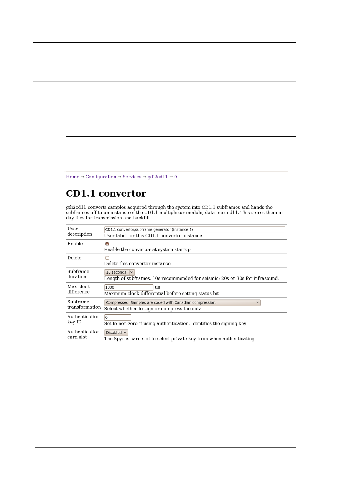
5.2.1 Configurable parameters in standard mode
There are a large number of standard options that can be
configured for the GDI to CD1.1 converter, so the basic
configuration screen is shown here in sections.
The User description is an alternative, human-readable label
for this instance. It is used, for example, in log files. If you are
building a complex application with several converters, you
should set this to something which describes the function of
this particular instance. In most cases, this can be left at the
default setting.
26 Issue C
Page 27

Operator's Guide
The Enable check-box controls whether this instance is to be
automatically started each time the system boots or whether it
should be left to be started manually.
The Delete check-box, if ticked, will cause this instance to be
deleted when the form is submitted.
The Subframe duration field controls the length of
subframes. Ten second subframes are recommended for
seismic recordings but some applications typically use longer
lengths. You can choose between ten and one hundred
seconds, inclusively, in ten second intervals.
The Max clock difference field is used to set the “clock
differential too large” bit (bit 1 of byte 4, the miscellaneous
status byte) in the CD1.1 channel subframe status block . If,
for example, a DM24 digitiser loses its GPS signal, it will use a
worst-case drift value to estimate the maximum difference
between its internal clock, now free-running, and GPS time, and
report this difference in its state-of-health information. The
converter will monitor this value and, should it exceed the
value set in this field, it will flag the resulting subframes to
indicate that the time-stamp can no longer be trusted. The
value is specified in microseconds.
The Subframe transformation drop-down menu controls
whether generated subframes are compressed and/or digitally
signed. The choices are:
• None. Samples are not compress and the subframe is
not signed.
• Compressed. Samples are coded with Canadian
compression.
• Signed. Samples are no compressed. The subframe is
signed.
• Compressed then signed. The subframes are
compressed, then the subframe signed.
The Authentication key ID field sets a flag in the CD1.1
header which some customers use to identify which encryption
key pair (from a pre-defined set) has been used. It is generally
set to be the serial number of the signing certificate. It should
be set to zero if frames are not to be signed.
June 2010 27
Page 28

CD1.1 Tools for Platinum
The Authentication card slot field is used when subframes
are signed. The Spyrus card used for signing can store
nineteen different key-pairs and this parameter selects which is
to be used. If signing is not required, this can be left set to
“disabled”.
The next section of the configuration screen controls channel
selection and channel name mapping. There is a channel
name mapping mode selection drop-down menu and a table of
channel names and associated parameters.
The channel name mapping mode selection drop-down menu
allows you to choose between three channel name mapping
modes:
• In automatic naming mode, the system will
automatically generate names for the output channels
based on the incoming channel name and any
associated meta-data. If the incoming channels have
usable names, they will not be changed.
• In semi-automatic mode, the mapping in the channel
name table will be used. Any channel not named in
the table will be mapped with an automatic name (as
in automatic mode).
• In manual mode, only the channels in the channel
name table will be used.
CD1.1 channels are named either STATION.CHANNEL or
STATION.CHANNEL.LOCATION where STATION consists of
between 1 and 5 characters, CHANNEL of between 1 and 3, and
LOCATION (if present) of between 1 and 2. Valid characters are
A-Z (upper-case only) and 0-9. The period character in the
name serves to separate the components of the name.
If desired, the instrument type and calibration for the channel
description fields may be entered into fields in the table. If left
empty ("auto" for instrument type), then gdi2cd11 attempts to
determine these values automatically.
The columns in the table are:
• System name — This is the name as used in gdi-
base.
28 Issue C
Page 29

Operator's Guide
• CD1.1 channel name, as
STATION.CHANNEL.LOCATION — this is either the
system-generated name (in automatic or semiautomatic naming mode) or the user-entered name (in
manual or over-ridden semi-automatic naming mode).
• Sensor type — this is a drop-down menu whose
options are “Automatically determined”, “Seismic”,
“Hydroacoustic”, “Infrasonic”, “Weather” and “Other”.
This is used to set the channel descriptor field in the
CD1.1 subframe. If this field is set to “Automatically
determined”, the type is assumed to be seismic.
• Calibration and Period — the values entered here
are transmitted in the channel subframe description.
Calibration is given in nm/count for a seismic sensor,
and period is in seconds. These fields expects floating
point numbers, so enter ”1.0” rather than just “1”.
Leaving these fields blank will result in it being
automatically populated with default values of 1.0. See
chapter 12 on page 74 for details.
• Delete — this check-box can be used to remove one or
more rows from the table when the form is submitted.
When in manual channel naming mode, this will
prevent the channel from being converted. This can be
used to filter certain channels to certain converters
when, for example, the application calls for different
subframe durations.
The final section of the configuration screen controls various
system monitoring options, both binary (on/off) and continuousvalued.
The CD1.1 header has a number of status bits (channel security
bits) with predefined meanings related to anti-tamper
precautions. The CMG-EAM has a number of general purpose
digital input/output lines which can be configured as inputs
from tamper-detection micro-switches and similar devices. The
first part of the “System monitoring” table allows the operator
to associate each status bit with a specific “tamper line”.
The status bits in the header which can be mapped in this way
are:
• Equipment housing open;
June 2010 29
Page 30

CD1.1 Tools for Platinum
• Digitising equipment open;
• Vault door opened;
• Authentication seal broken;
• Equipment moved;
• Future use (channel security bit 6);
• Future use (channel security bit 7); and
• Future use (channel security bit 8).
For each of these, the “tamper line” that should set this bit can
be selected from a drop-down menu. The options on those
menus vary considerably depending on the precise hardware
configuration of the CMG-EAM. You must enable tamper line
monitoring for each line you wish to use here: this is done in
the GPIO configuration page (directly accessible from the toplevel configuration menu).
Various continuous values, such as voltages and temperatures,
can also be monitored and compared to configurable threshold
values. If the threshold is exceeded, a status bit can be set in
the CD1.1 header.
The bits that can be controlled in this way are “Main power
failure” and “Backup power unstable”. For each of these, a
value to be monitored and a threshold value can be configured.
The value to be monitored is chosen from a drop-down menu.
The items on this menu vary with the precise hardware
configuration of the CMG-EAM but typically include the choice
of voltage, current or power for each monitored power bus.
You must enable line monitoring for each value that you wish
to use here: this is done in the GPIO configuration page
(directly accessible from the top-level configuration menu).
After the voltage indicator byte in the CD1.1 header, there are
three reserved bytes available for future use. If desired, these
can be populated with three sets of eight-bit digitised property
values. The final part of the “System monitoring” table allows
the operator to select which properties are used to populate
these bit-fields and the scaling (units) to be used.
30 Issue C
Page 31

Operator's Guide
For each of the three bit-fields, the associated property can be
selected from a drop-down menu. The items on this menu vary
with the precise hardware configuration of the CMG-EAM but
typically include the choice of voltage, current or power for
each monitored power bus. The scaling is also set by a dropdown menu, whose choices are:
• Current: -1.28A to 1.27A where one bit equals 10mA
• Voltage: 5.0V to 30.5V where one bit equals 0.1V
• Power or temperature: -64 to 63.5 where one bit
equals 0.5W or 0.5°C (in units of Watts or Celsius, as
appropriate).
5.2.2 Configurable parameters in expert mode
The following additional configuration options appear when the
“Expert mode” button is pressed:
The Log file field allows a separate log-file to be maintained,
dedicated to this converter instance. When left blank, the
standard syslog subsystem is used and, for most applications,
this is adequate. For extremely complex set-ups, it may be
useful to segregate messages from this instance into a
separate file.
Whether logging to syslog or to a dedicated file, the Log level
pull-down menu allows you to select the level of detail that will
be logged. The options are a subset of the standard syslog
levels: “Warnings”, “Important notices”, “Informational
messages” and “Debugging information”. Setting this field to
“Warnings” produces the least output and setting it to
“Debugging information” produces the most.
June 2010 31
Page 32

CD1.1 Tools for Platinum
The converter takes its input from an instance of gdi-base and
writes its output to an instance of data-mux-cd11. In most
applications, there will be only one instance of each and the
remaining two fields, GDI multiplexor and CD1.1
multiplexor can be left at their default values. When building
more complex configurations, it may be necessary to have
more than one instance of one or both of these modules.
These fields let you select, for the converter, which instance of
gdi-base to use for input and which instance of data-muxcd11 to use for output. All configured instances appear on the
associated drop-down menus.
32 Issue C
Page 33

Operator's Guide
6 Using the CD1.1 Receiver
The data-in-cd11 module receives CD1.1 frames from
external CD1.1 Data Producers (DPs). It is typically used at an
array data centre, where it receives data frames from any DPs
in the array; typically each array element or station will have
its own CD1.1 sender. The receiver is responsible for tracking
the sequence numbers of received frames and issuing
retransmission requests when missing frames are detected.
Received frames are passed to the data-mux-cd11 module for
storage and forwarding.
6.1 Creating a new CD1.1 receiver instance
In the web interface, select “Configuration -> Services” from
the left-hand menu or from the command line, run
gconfig
and then select “System services”.
Now choose “data-in-cd11 -- CD1.1 receiver” to view a list of
configured receiver instances. You can choose to either
configure any existing instance (as described in the following
section) or select “Create new service instance” to create a
new one.
A form is displayed which allows you to set various parameters
for the instance. Each parameter is discussed in the following
section. After entering the desired configuration for the
instance, choose Submit.
This will create (if it is new) and configure the receiver
instance. If it is not already running, you can start it by using
“Control -> Services” on the web menu or by running
/etc/init.local/data-in-cd11.0 start
from the command line.
The zero after the period in the command name determines
which receiver instance is to be started, so the command to
start a second instance would be
/etc/init.local/data-in-cd11.1 start
June 2010 33
Page 34

CD1.1 Tools for Platinum
6.2 Configuration options for the receiver
There are two levels of configuration options available:
standard and expert. The configuration screen is first displayed
in standard mode but extra options can be displayed by
clicking the “Expert” button at the bottom of the form.
6.2.1 Configurable parameters in standard mode
The configuration screen for the receiver is shown here in two
parts.
The User description is an alternative, human-readable label
for this instance. It is used, for example, in log files. If you are
building a complex application with several receivers, you
should set this to something which describes the function of
this particular instance. In most cases, this can be left at the
default setting.
The Enable check-box controls whether this instance is to be
automatically started each time the system boots or whether it
should be left to be started manually.
The Delete check-box, if ticked, will cause this instance to be
deleted when the form is submitted.
34 Issue C
Page 35

Operator's Guide
The Receiver name field identifies this receiver instance to
communicating senders, according to the CD1.1 protocol. This
name should be unique.
The Station type drop-down menu is also used to identify the
receiver. It can be set to “IMS (international monitoring
system)”, “NDC (national data centre)” or “IDC (international
data centre)”.
If a CMG-EAM has multiple network addresses configured, it
may be desirable to listen on only one of them. Similarly, if a
CMG-NAM has multiple network adapters installed, then a
receiver instance would typically only be concerned with one of
them. The Bind host field can be used to restrict the receiver
instance to listen on only a single address. Leaving this field
set to the default of 0.0.0.0 instructs the receiver to listen to all
configured interfaces and addresses. If any other address is
specified, the receiver will only listen on that address (and the
associated network adapter).
The Bind service field specifies the port (service) on which the
receiver instance should listen. This can be specified
numerically or by name. Port names are converted to numeric
ports using the standard Linux /etc/services file.
The second part of the receiver configuration screen is
illustrated below:
When an incoming CD1.1 connection request packet is
received, the receiver must respond with a packet containing
an I.P. address and port number. The real connection is then
made using these parameters.
June 2010 35
Page 36

CD1.1 Tools for Platinum
The Connect host field should be populated with the address
to which the actual data connection should be made. Where
the receiver is running on a CMG-EAM directly connected to the
Internet, this will be the I.P. address of the CMG-EAM and the
port number specified as Bind service, above. If the CMGEAM is behind a firewall or NAT device, however, it may be
necessary to specify the I.P. address of the firewall.
Similarly, the Connect service field should be populated with
the port (name or number) to which the incoming connection
should be made, which may differ from the Bind Service port
if NAT or another translation scheme is being used.
The receiver must be configured ahead of time with a list of
DPs from which it is to expect connections. This should be
provided in the Sender list field. If a sending station's
connection request frame contains a name other than the ones
listed in this field, it is rejected. Individual station names in the
list should be separated by spaces.
6.2.2 Configurable parameters in expert mode
The following additional configuration options appear when the
“Expert mode” button is pressed:
The Log file field allows a separate log-file to be maintained,
dedicated to this receiver instance. When left blank, the
standard syslog subsystem is used and, for most applications,
this is adequate. For extremely complex set-ups, it may be
useful to segregate messages from this instance into a
separate file.
Whether logging to syslog or to a dedicated file, the Log level
pull-down menu allows you to select the level of detail that will
be logged. The options are a subset of the standard syslog
36 Issue C
Page 37

Operator's Guide
levels: “Warnings”, “Important notices”, “Informational
messages” and “Debugging information”. Setting this field to
“Warnings” produces the least output and setting it to
“Debugging information” produces the most.
The receiver writes its output to an instance of data-mux-cd11.
In most applications, there will be only one instance of this and
the CD1.1 multiplexor field can be left at its default value.
When building more complex configurations, it may be
necessary to have more than one multiplexor instance. This
fields let you select which instance of data-mux-cd11 to use for
output. All configured instances appear on the associated
drop-down menu.
6.3 Operation notes
The receiver module does not verify authentication data on
incoming frames. It does not decode the subframes: they are
passed, unmodified and still encoded, straight to a multiplexor
module.
This means that the Platinum firmware cannot currently
convert waveform data from a CD1.1 DP into other seismic
formats, although this functionality may be added in future.
Note that each receiver module is capable of receiving from
more than one DP; the only reason to have more than one
receiver is if the receiver name/type needs to differ, or if the
data needs to be sent to a different multiplexor module.
There is currently no tool to interact with the receiver database
file but it can be removed altogether to stop any acknack
requests from occurring when the module is started up.
June 2010 37
Page 38

CD1.1 Tools for Platinum
7 Using the CD1.1 Sender
This module is responsible for receiving subframes from the
multiplexor, assembling them into full CD1.1 frames,
transmitting them to a remote receiver (and logging the
transmissions), handling back-fill, satisfying retransmission
requests and digitally signing frames.
Note that the CD1.1 sender module does not require or verify
authentication data on frames it receives from the Data
Consumer (DC).
On start-up, the sender attempts to connect to the DC. The DC
responds to the connection request with a redirection
notification, which contains an I.P. address and port number, to
which the sender is required to re-connect. Progress in
connecting (including the redirected address) will be logged via
syslog (i.e. into /var/log/messages) or to the configured logfile. Once connected, the sender waits for sets of subframes
from the CD1.1 multiplexor and sends them as a packaged
frame to the DC. After sending each frame, if the TCP output
buffer is empty, the sender will check for any outstanding backfill and, if required, transmit a back-filled frame.
7.1 Back-filling and retransmission
Back-fill occurs if the sender is disconnected from the DC for a
period of time. Retransmission occurs if the DC sends an
acknack frame detailing one or more gaps in its reception
record.
Whenever a real-time (i.e. not back-filled) data frame is
transmitted, its time-stamp is recorded in a database. If this
time-stamp does not match the previously- recorded timestamp plus the subframe duration, a back-fill gap is noted in
this database file. This allows the output module to be turned
off, or to crash, while ensuring that gaps are still recorded. It
also deals with the situation where a connection to the DC
becomes unavailable; once the connection is re-established,
the first frame to be transmitted will cause the output module
to realise there is a gap and it can then be back-filled correctly.
In this context, transmission counts as the frame being written
to the TCP socket correctly, and does not take into account
whether the DC has successfully received the frame. If the DC
does miss the frame due to, say a lost packet on the network
38 Issue C
Page 39

Operator's Guide
link, it will be recovered and retransmitted later when the DC
sends an acknack frame.
Whenever any frame is transmitted, it is assigned a sequential
sequence number. A second database file, the framedb,
records the sequence numbers against the time-stamps of the
frames being transmitted. The DC periodically produces an
acknack frame which indicates which of those frames have
been successfully received; once a frame has been
acknowledged, it is purged from the frame database file.
If the acknack frame indicates that the DC has a gap, the frame
database file is consulted to find the time-stamp of the missed
frame(s), and those frames are added to the list for
retransmission.
Tools are provided to maintain the two database files. See
Section 9.2 on page 56 for more details.
7.2 Creating a new CD1.1 sender instance
In the web interface, select “Configuration -> Services” from
the left-hand menu or from the command line, run
gconfig
and then select “System services”.
Now choose “data-out-cd11 -- CD1.1 sender” to view a list of
configured sender instances. You can choose to either
configure any existing instance (as described in the following
section) or select “Create new service instance” to create a
new one.
A form is displayed which allows you to set various parameters
for the instance. The default values are suitable for most
applications but each parameter is discussed in the following
section. After entering the desired configuration for the
instance, choose Submit.
This will create (if it is new) and configure the sender instance.
If it is not already running, you can start it by using “Control ->
Services” on the web menu or by running
/etc/init.local/data-out-cd11.0 start
from the command line.
June 2010 39
Page 40

CD1.1 Tools for Platinum
The zero after the period in the command name determines
which sender instance is to be started, so the command to
start a second instance would be
/etc/init.local/data-out-cd11.1 start
7.3 Configuration options for the sender
There are two levels of configuration options available:
standard and expert. The configuration screen is first displayed
in standard mode but extra options can be displayed by
clicking the “Expert” button at the bottom of the form.
7.3.1 Configurable parameters in standard mode
There are a large number of standard options that can be
configured for the CD1.1 sender, so the basic configuration
screen is shown here in sections.
The User description is an alternative, human-readable label
for this instance. It is used, for example, in log files. If you are
building a complex application with several senders, you should
40 Issue C
Page 41

Operator's Guide
set this to something which describes the function of this
particular instance. In most cases, this can be left at the
default setting.
The Enable check-box controls whether this instance is to be
automatically started each time the system boots or whether it
should be left to be started manually.
The Delete check-box, if ticked, will cause this instance to be
deleted when the form is submitted.
The Station name field identifies this sender instance to
communicating Data Consumers (DCs), according to the CD1.1
protocol. This name should be unique and is normally set using
the system's hostname.. The station name field is also used as
the “frame creator” for frameset naming.
The Station type drop-down menu is also used to identify the
sender in connection request frames. It can be set to “IMS
(international monitoring system)”, “NDC (national data
centre)” or “IDC (international data centre)”.
The Data consumer well-known address field should be
populated with the I.P. address or DNS name of the DC
(receiver) to which frames should be sent. If a name is used, it
is first looked up in the standard Linux /etc/hosts file; if no
match is found, the configured DNS server is queried.
The Data consumer well-known port field should be
populated with the port (service) number or name to which
frames should be sent at the DC. If a name is used, it is looked
up in the standard Linux /etc/services file.
Note that these two fields only specify the “well-known DC
address”; as part of the connection establishment, the
receiving system will redirect the sender to another
port/address. The redirection will be logged via the configured
logging mechanism (syslog or file).
The Spyrus card used for checking signatures can store
nineteen different key-pairs and the Spyrus card slot dropdown menu selects which is to be used. If the sender should
not sign packets, this can be left set to “disabled”.
The Authentication key ID field sets a flag in the CD1.1
header which some customers use to identify which encryption
key pair (from a pre-defined set) has been used. It is generally
June 2010 41
Page 42

CD1.1 Tools for Platinum
set to be the serial number of the signing certificate and should
be set to zero if signing is not used.
The Backfill policy drop-down menu controls the order in
which requested back-fill frames are transmitted. The options
are “LIFO (last in, first out -- CTBTO preferred)” and “FIFO (first
in, first out -- time series)”.
The next section of the configuration screen is the Channels
table, which controls channel filtering: i.e. which channels are
to be transmitted by this sender instance. The on-screen text
explains its use.
To transmit all but a few channels, list the channels to omit and
leave the accept check-boxes un-ticked.
To transmit only a few channels, list the channels to send, tick
their “Accept” check-boxes and, as the final line, enter the
wild-card sequence:
_ _ _ _ _._ _ _._ _
with the check-box un-ticked. (The above line contains five
underscores, a period, three underscores, a period and two
underscores, with no spaces.)
Some further examples of filter rows follow.
42 Issue C
Page 43

Operator's Guide
• To make a filter row which rejects all subframes from
the station “TEST”, enter a filter row with Accept
unchecked and a Channel field of “TEST.___.__”.
• To make a filter row which rejects all subframes from
vertical channels, enter a filter row with Accept
unchecked and a Channel field of “_____.__Z.__”.
• To make a filter row which matches only broadband,
high-gain channels, enter a filter row with Accept
checked and a Channel field of ”_____.BH_.__”.
Combining filter rows allows you to build a complete filter. For
example, to make the sender only send broadband, high-gain
channels (but not from the TEST station), you would use this
filter:
Row 1: Accept unchecked, Channel “TEST.___.__”.
Row 2: Accept checked, Channel “_____.BH_.__”.
Row 3: Accept unchecked, Channel “_____.___.__”.
The first row rejects all channels from the TEST station.
Unmatched channels (i.e. those from another station) will
continue to the second row, which accepts any channel whose
name starts BH (regardless of component). Channels which do
not match continue to the third row, which simply rejects
everything else.
The final parameter on this screen enables or disables the
Transmission log, which is described in the on-screen text.
Setting up a directory cleaner, as recommended in the onscreen text, is described in Section 8.1 on page 45.
June 2010 43
Page 44

CD1.1 Tools for Platinum
7.3.2 Configurable parameters in expert mode
The following additional configuration options appear when the
“Expert mode” button is pressed:
The Log file field allows a separate log-file to be maintained,
dedicated to this sender instance. When left blank, the
standard syslog subsystem is used and, for most applications,
this is adequate. For extremely complex set-ups, it may be
useful to segregate messages from this instance into a
separate file.
Whether logging to syslog or to a dedicated file, the Log level
pull-down menu allows you to select the level of detail that will
be logged. The options are a subset of the standard syslog
levels: “Warnings”, “Important notices”, “Informational
messages” and “Debugging information”. Setting this field to
“Warnings” produces the least output and setting it to
“Debugging information” produces the most.
The sender takes its input from an instance of data-mux-cd11.
In most applications, there will be only one instance of this and
the CD1.1 multiplexor field can be left at its default value.
When building more complex configurations, it may be
necessary to have more than one instance of the multiplexor.
This fields lets you select, for the sender, which instance of
data-mux-cd11 to use for input. All configured instances
appear on the associated drop-down menu.
The final field, Database directory, controls where the
transmission log files, as described above, are stored. These
may be stored on additional flash memory, if fitted: See
Section 13 on page 79 for more details.
44 Issue C
Page 45

Operator's Guide
8 Frame database files
The CD1.1 multiplexor stores subframes on disk in a simple
database file, indexed by time. One database file is created
per day.
By default, these database files are stored under /var/lib, but
some CMG-EAM modules have additional flash storage
mounted under /media/flash_module, so it may be
advantageous (where extra capacity is required) to reconfigure
the multiplexor to store its database files in a subdirectory in
this location (see the Database directory field in Section
4.2.1 on page 22 and Section 13, “Optional flash memory” on
page 79).
The first section of the database file contains 8640 pointers
(one for each possible frame start time within a 24-hour
period), which allows the multiplexor to quickly jump to the first
subframe received for a given time-stamp.
When new subframes are received, they are stored into the
database file, creating a new one if necessary. When the data
frame transmission period timer expires, all subframes for a
given time-stamp are read back from the database file and
transmitted to each connected output module. In addition, any
output module can request all subframes for a given timestamp, which allows the implementation of back-fill.
8.1 Managing database files
If left unattended, the database files will continue to grow as
subframes are received until the system runs out of secondary
storage (flash or hard disk space).
Files are named by ordinal day (YYYY-DDD in ISO8601
notation).
The files can either be manually managed, or an automatic task
to periodically prune old files can be created. To do this, in the
web interface, select “Configuration -> Tasks” from the lefthand menu or from the command line, run
gconfig
and select “Routine tasks”.
June 2010 45
Page 46

CD1.1 Tools for Platinum
Select “Directory cleaner” and then “Setup cleaning in new
directory”.
The resulting form allows you to configure all options of the
directory cleaning task. Each cleaner handles a single
directory so it is necessary to create multiple cleaner instances
for all but the simplest applications.
The directory cleaner configuration screen looks like this:
Enter the full path to the database directory (e.g.
/var/lib/data-mux-cd11.0 or /media/flash_module/datamux-cd11.0) into the Directory field.
It is possible to limit the files either by size or by number (or by
both).
• To ensure at least 14 complete days of back-fill, enter
“15” into the Maximum number of files field.
• To ensure used space is kept to 200MiB or just above,
enter “200” into the Maximum used space field.
Scanning occurs once an hour and, if there are more files or
space used than the configured maximum, some will be
removed. Using Lexical file sorting ensures the oldest data will
46 Issue C
Page 47

Operator's Guide
be removed first (see the configuration help for more
information).
8.2 Examining database files
A command line program, cd11-timedb-tool, can be used to
examine the database files - see Section 9.2.3 on page 60 for
details.
June 2010 47
Page 48

CD1.1 Tools for Platinum
9 Logging and analysing
9.1 Web-based tools
The web interface provides three tools for analysing CD1.1
module log files. To access them, select “CD1.1 log analyser”
from the main menu. The following screen appears:
The menu will automatically extend itself if additional instances
of any module are created. The three tools are considered in
detail below.
9.1.1 Multiplexer log analysis tool
The multiplexor log analysis tool displays a day's worth of log
file entries, grouped by hour, along with the number of entries
for each hour.
Clicking any “View” link take you to a detail screen for the
associated hour.
48 Issue C
Page 49

Operator's Guide
The detail screen displays a table, where the first column
shows the time-stamp for each subframe processed and the
second column gives the number of channels processed for
that time-stamp. If a gap has been detected, this is clearly
indicated, in red, in the first column. Subsequent columns are
labelled with CD1.1 channel names and are populated either
with the word “missing”, if no subframe was received for the
given channel with the given time-stamp, or with a quadrant
status indicator, as shown in the following diagram. Each
quadrant of the circle is labelled with a mnemonic identifier
and will be either red or green, depending on the status of the
associated subsystem. Green is used to indicate a satisfactory
status and red indicates some cause for concern.
June 2010 49
Page 50

CD1.1 Tools for Platinum
• The top left quadrant, 'S', displays the signature status: It
is green if the subframe is signed and red if unsigned.
• The bottom left quadrant, 'G', shows the GPS lock status:
It is green if locked and red if unlocked.
• The bottom right quadrant, 'T', represents the timing
status: It is green if the clock differential is acceptable
and red if it has exceeded the configured threshold.
• The top right quadrant, 'M', depicts “miscellaneous”
status: it is green if everything is satisfactory but turns
red if any channel, security or misc. status bit is set.
The quadrant indicator also serves as a link to the subframe
decoder, where the entire contents of the subframe are
displayed broken into fields, along with the interpretation of the
contents. The top of such a display is shown below:
50 Issue C
Page 51

Operator's Guide
9.1.2 Receiver log analysis tool
The CD1.1 receiver log analysis tool can be used to examine
the performance of the CD1.1 receiver.
To access it, select “CD1.1 log analyser” from the main menu.
The following screen appears:
The menu will automatically extend itself if additional instances
of any module are created. Clicking the link for the desired
receiver instance produces a screen like this:
June 2010 51
Page 52

CD1.1 Tools for Platinum
A link will be displayed for each connected client, along with
the number of gaps currently being tracked. Clicking on a
client link produces a screen like this:
There will be an entry in the table for each contiguous set of
frames (i.e. there will be one more populated row than there
are reported gaps). As indicated in the display, the frame
identified by the “End sequence number” will not yet have
been received.
9.1.3 Sender log analysis tool
The CD1.1 sender log analysis tool can be used to query the
unacknowledged frame database, the back-fill database and
the transmission log.
To access it, select “CD1.1 log analyser” from the main menu.
The following screen appears:
52 Issue C
Page 53

Operator's Guide
The menu will automatically extend itself if additional instances
of any module are created. Clicking the link for the desired
sender instance produces a screen like this:
The first bulleted line gives the number of entries in the
unacknowledged frame database, which also serves as a link to
a summary view. Note that, while it is not possible to edit the
unacknowledged frame database via the web interface, a
command line tool, cd11-framedb-tool, provides this
functionality if required. See section 9.2.2 on page 59 for
further details.
The summary view of the unacknowledged frame database
looks like this:
June 2010 53
Page 54

CD1.1 Tools for Platinum
The second bulleted line shows the number of entries in the
back-fill database, i.e. the number of frames which have been
requested to be transmitted as back-fill but which not yet been
sent. The number also serves as a link to a summary view.
Note that, while it is not possible to edit the back-fill database
via the web interface, a command line tool, cd11-backfilldb-
tool, provides this functionality if required. See section 9.2.1
on page 57 for further details.
The summary view of the back-fill database looks like this:
The two database summaries are followed by the transmission
log search tool and a list of all transmission log files: it is on
these files that the search tool operates.
54 Issue C
Page 55

Operator's Guide
Clicking the search tool link (“scan for transmission of a
particular frame”) produces the following screen:
This screen allows the operator to enter a time datum with
which to search the transmission log files. Note that the time
datum is compared with the time-stamp on the transmitted
frames, not the log-file entry time-stamps.
Entering, for example, “2009-340T22:00:10” and clicking “Scan
logs” might give the following display:
June 2010 55
Page 56

CD1.1 Tools for Platinum
All matching log-file entries are displayed along with sequence
number, authentication and channel details. Clicking on the
link in the “Log entry” column displays the complete log file.
The complete log file can also be displayed by clicking on any
of the links under “Available log files” on the front page of the
CD1.1 sender log analysis tool. A typical log file looks like this
(only the first few entries are shown:
Note that the frame transmission details are preceded by the
results of a complete file scan, which checks for any data
quality indicators which are not optimal, gaps in the frame
sequence or out-of-order transmissions.
9.2 Command-line tools
The following command-line tools are available for analysing
and managing CD1.1 log files and database files:
• cd11-backfilldb-tool - used to summarise, dump,
clear, partially clear or add entries to the back-fill
database used by the CD1.1 sender, data-out-cd11.
• cd11-framedb-tool - used to summarise, dump, clear
or partially clear the frame database maintained by the
CD1.1 sender, data-out-cd11.
56 Issue C
Page 57

Operator's Guide
• cd11-timedb-tool - used to summarise or display
headers from the frames database maintained by the
CD1.1 multiplexer, data-mux-cd11.
• cd11-frame-analyser-tool - used to dump and
decode a CD1.1 frame (or multiple frames), either as
they are received or selected by time-stamp.
• cd11-management-tool - used to change the logging
level of any of the CD1.1 modules without restarting
them, and/or to change the authentication key ID.
All of these tools have detailed usage messages which are
accessible by invoking the tool with, as an argument, either -h
or --help.
9.2.1 cd11-backfilldb-tool
The CD1.1 sender, data-out-cd11, maintains a database of untransmitted or unacknowledged frames, which it uses to
perform back-fill. In normal operation with good network links,
this database is quite likely to be empty.
The command-line program cd11-backfilldb-tool allows the
listing, addition or removal of frames for which back-fill is to be
performed.
The back-fill database file for the first sender instance is
normally /var/lib/data-out-cd11.0/backfilldb - other
instances use similar path-names with the “0” incremented for
each instance. The tool should be invoked with the path to the
back-fill database as the last argument.
If no other arguments are given, the tool reports the most
recent frame time-stamp and the number of gaps (contiguous
sequences of missing frames) in the database:
eam999 # cd11-backfilldb-tool /var/lib/data-out-
cd11.0/backfilldb
Most recent timestamp : 2009-12-06T23:40:40Z
Number of missing ranges: 2
This is the same behaviour as when the -s (or --summary)
argument is given.
Giving the -d (or --detail) argument displays a table showing
the start and end time-stamps for each gap:
June 2010 57
Page 58

CD1.1 Tools for Platinum
eam999 # cd11-backfilldb-tool -d /var/lib/data-outcd11.0/backfilldb
Most recent timestamp: 2009-12-06T23:40:40Z
Gap start | Gap end
--------------------------+--------------------------- 2009-12-06T21:25:20Z 2009-12-06T21:32:10Z
2009-12-06T21:42:40Z 2009-12-06T22:53:50Z
EOF
Using the -c (or --clear-before) argument with a date (in the
same format as those produced on output) removes all entries
for gaps before the given date. No further attempt will be
made to send these frames unless they are specifically
requested by the DC with an acknack packet.
Using the -C (or --clear-all) argument removes all entries
from the back-fill database. This ensures that no back-fill takes
place when the module is started (this does not apply to
retransmission requests issued by the DC via the acknack
mechanism). This could be used to prune older data, ensuring
only fresh data is back-filled after a long outage.
Using the -a (or --add) argument with two dates (in the same
format as those produced on output) separated by only a
forward-slash character (“/”) adds a spurious gap to the
database:
eam999 # cd11-backfilldb-tool -a 2009-12-01T12:00:00Z/200912-01T12:59:50Z /var/lib/data-out-cd11.0/backfilldb
No output is produced on successful database modification but
the new database entry can be seen using the -d command:
eam999 # cd11-backfilldb-tool -d /var/lib/data-outcd11.0/backfilldb
Most recent timestamp: 2009-12-06T23:40:40Z
Gap start | Gap end
--------------------------+--------------------------- 2009-12-01T12:00:00Z 2009-12-01T12:59:50Z
2009-12-06T21:25:20Z 2009-12-06T21:32:10Z
2009-12-06T21:42:40Z 2009-12-06T22:53:50Z
EOF
Full usage details for this program can be produced by passing
it the -h (or --help) flag:
Usage:
cd11-backfilldb-tool [options] /path/to/backfilldb
Valid options:
-h, --help Display this screen.
58 Issue C
Page 59

Operator's Guide
-V, --version Display version number.
-s, --summary Display summary of backfilldb.
-d, --detail Dump details (entries) of
backfilldb.
-c, --clear-before <date> Clear entries before <date> from
backfilldb.
-C, --clear-all Clear all entries from
backfilldb.
-a, --add <date>/<date> Add an entry between two dates.
The default action is to display a summary of the database.
This tool should only be used to modify the database when
data-out-cd11 is not running. Actions are executed in
reverse order to the commandline.
9.2.2 cd11-framedb-tool
The CD1.1 sender, data-out-cd11, maintains a database of
transmitted frames, mapping its sequence numbers to their
channels and time-stamps. Where multiple senders transmit a
common subset of frames, one frame can have different
sequence numbers, when seen from the points of view of the
different senders. If a Data Consumer (DC) requests
retransmission of a packet, it will do so by sequence number
but the multiplexer stores frames by channel and time-stamp.
The frame database allows the sender to receive the
retransmission request from the DC by sequence number and,
subsequently, to pass the request on to the multiplexer by
channel and time-stamp.
The command-line program cd11-framedb-tool allows the
listing or removal of frames from this database.
The frame database file for the first sender instance is normally
/var/lib/data-out-cd11.0/framedb - other instances use
similar path-names with the “0” incremented for each instance.
The tool should be invoked with the path to the frame database
as the last argument.
If no other arguments are given, the tool provides a brief
summary of the contents of the database, as shown below.
eam999# cd11-framedb-tool /var/lib/data-out-cd11.0/framedb
Most recent sequence number : 38295
First unacknowledged sequence number: 38293
frame date: 2009-12-06T23:40:20Z
Last unacknowledged sequence number: 38295
frame date: 2009-12-06T23:40:40Z
eam999#
June 2010 59
Page 60

CD1.1 Tools for Platinum
The behaviour is identical when using the -s (or --summary)
argument.
A more detailed analysis of the contents of the database can be
gleaned by giving the -d (or --detail) argument:
eam999 # cd11-framedb-tool -d /var/lib/data-outcd11.0/framedb
Last sequence number transmitted: 38295
Sequence | Datestamp
---------------------+----------------------------- 38293 | 2009-12-06T23:40:20Z
38294 | 2009-12-06T23:40:30Z
38295 | 2009-12-06T23:40:40Z
EOF
eam999 #
Using the -c (or --clear-before) argument with a date (in the
same format as those produced on output) removes all entries
before the given date. These frames will be considered to have
been acknowledged by the DC.
Using the -C (or --clear-all) argument removes all entries
from the frame database.
Full usage details for this program can be produced by passing
it the -h (or --help) flag:
Usage:
cd11-framedb-tool [options] /path/to/framedb
Valid options:
-h, --help Display this screen.
-V, --version Display version number.
-s, --summary Display summary of framedb.
-d, --detail Dump details (entries) of
framedb.
-c, --clear-before <seq> Clear entries before <seq> from
framedb.
-C, --clear-all Clear all entries from framedb.
The default action is to display a summary of the database.
This tool should only be used to modify the database when
data-out-cd11 is not running. Actions are executed in
reverse order to the commandline.
9.2.3 cd11-timedb-tool
The CD1.1 multiplexer, data-mux-cd11, records every frame it
sends, as it sends it, in a daily database file, called the timedb.
The actual database files have names like 2009-348, where
60 Issue C
Page 61

Operator's Guide
2009 is the year and 348 is the day number within that year, as
specified in ISO8601.
Each instance of the multiplexer has a configurable directory in
which these files are stored (see Database directory in
Section 4.2.1 on page 22). The default directory for the first
multiplexer instance is /var/lib/data-mux-cd11.0/ where the
'0' varies with instance.
The cd11-timedb-tool command-line tool allows this database
to be queried. The path to a database file should be given as
an argument to the tool. Used without further options, the tool
produces a summary of the entries in the database file, listed
hour by hour, with the number of frames stored for each hour,
as below. The output is shown truncated here:
eam999# cd11-timedb-tool /var/lib/data-mux-cd11.0/2009-348
timedb version 0 file
00:00:00--00:59:59 : 360 frames
01:00:00--01:59:59 : 360 frames
02:00:00--02:59:59 : 360 frames
03:00:00--03:59:59 : 360 frames
04:00:00--04:59:59 : 360 frames
05:00:00--05:59:59 : 360 frames
......
21:00:00--21:59:59 : 360 frames
22:00:00--22:59:59 : 360 frames
23:00:00--23:59:59 : 360 frames
eam999#
Additional information can be displayed by using the -v (or
--verbose) argument. The summary display, as above, is
produced and then, for each time-stamp within the daily
database file, the channel, subframe size and transmission
status are given:
eam999# cd11-timedb-tool -v /var/lib/data-mux-cd11.0/2009-
348
timedb version 0 file
00:00:00--00:59:59 : 360 frames
01:00:00--01:59:59 : 360 frames
02:00:00--02:59:59 : 360 frames
......
21:00:00--21:59:59 : 360 frames
22:00:00--22:59:59 : 360 frames
23:00:00--23:59:59 : 360 frames
-------- 00:00:00
3K55.HHZ. (600 bytes, already transmitted)
3K55.HHN. (600 bytes, already transmitted)
3K55.HHE. (600 bytes, already transmitted)
-------- 00:00:10
3K55.HHE. (600 bytes, already transmitted)
June 2010 61
Page 62

CD1.1 Tools for Platinum
3K55.HHZ. (600 bytes, already transmitted)
3K55.HHN. (600 bytes, already transmitted)
-------- 00:00:20
3K55.HHE. (600 bytes, already transmitted)
3K55.HHZ. (600 bytes, already transmitted)
3K55.HHN. (600 bytes, already transmitted)
......
-------- 23:59:40
3K55.HHZ. (600 bytes, already transmitted)
3K55.HHN. (600 bytes, already transmitted)
3K55.HHE. (600 bytes, already transmitted)
-------- 23:59:50
3K55.HHZ. (600 bytes, already transmitted)
3K55.HHN. (600 bytes, already transmitted)
3K55.HHE. (600 bytes, already transmitted)
eam999#
Full usage details for this program can be produced by passing
it the -h (or --help) flag:
Usage:
cd11-timedb-tool [options] file
Options:
-h, --help Display this screen.
-V, --version Display version number.
-v, --verbose Display details of timedb.
Default if no options are specified is to display a summary
of the database file. Pass --verbose to see subframe
headers.
9.2.4 cd11-frame-analyser-tool
The command-line tool cd11-frame-analyser-tool can be run
to receive and decode sets of subframes being transmitted
from the multiplexor. The output from this program is suitable
for sending to a script in order to monitor the status bits, etc.
The program requires the -s (or --socket) option to be given
with, as an argument, the path to the IPC socket being used by
the desired multiplexor instance. For the first instance, this
path is
/var/run/data-mux-cd11.0
and subsequent instances have similar paths, with the final “0”
being incremented for each instance.
Run with no further options, the tool displays a summary of the
first frame to be assembled by the multiplexer after the
62 Issue C
Page 63

Operator's Guide
command is invoked. This usually involves a delay of ten
seconds or more between invocation and output. The
summary looks like this:
eam999 # cd11-frame-analyser-tool -s /var/run/data-muxcd11.0
Frame at 2009355 15:51:00.000: 3 channels, 10000ms duration
Channel 3K55.HHZ.
Channel 3K55.HHN.
Channel 3K55.HHE.
eam999 #
More output is produced if the -v (or --verbose) option is
given. The previous display is produced and this is followed by
a display of the subframe flags for each channel.
eam999 # cd11-frame-analyser-tool -v -s /var/run/data-muxcd11.0
Frame at 2009355 16:03:30.000: 3 channels, 10000ms duration
Channel 3K55.HHZ.
Channel 3K55.HHN.
Channel 3K55.HHE.
Subframe for channel 3K55.HHZ. (at 2009355 16:03:30.000,
duration 10000ms)
subframe_length=600 auth_offset=596
auth_flag=0 trans_type=1 sensor_type=1
option_flag=1
cal_factor=3.000 cal_period=0.500 num_samples=800
status_format=1 status_len=32
status_data=0x00 status_security=0x00
status_misc=07 status_voltage=03
last_gps_sync=1989321 00:00:00.000
clock_differential=-2147483647us
auth_key_id=0 auth_size=0
Subframe for channel 3K55.HHN. (at 2009355 16:03:30.000,
duration 10000ms)
subframe_length=600 auth_offset=596
auth_flag=0 trans_type=1 sensor_type=3
option_flag=1
cal_factor=1.000 cal_period=1.000 num_samples=800
status_format=1 status_len=32
status_data=0x00 status_security=0x00
status_misc=07 status_voltage=03
last_gps_sync=1989321 00:00:00.000
clock_differential=-2147483647us
auth_key_id=0 auth_size=0
Subframe for channel 3K55.HHE. (at 2009355 16:03:30.000,
duration 10000ms)
subframe_length=600 auth_offset=596
auth_flag=0 trans_type=1 sensor_type=1
option_flag=1
cal_factor=1.000 cal_period=1.000 num_samples=800
status_format=1 status_len=32
status_data=0x00 status_security=0x00
status_misc=07 status_voltage=03
June 2010 63
Page 64

CD1.1 Tools for Platinum
last_gps_sync=1989321 00:00:00.000
clock_differential=-2147483647us
auth_key_id=0 auth_size=0
eam999 #
If the -c (or --continuous) option is given, the tool will not exit
after displaying the first frame: rather, it will continue to
decode frames as they are received until interrupted by a ^C.
Full usage details for this program can be produced by passing
it the -h (or --help) flag:
Usage:
cd11-frame-analyser-tool [options] [timestamp]
Valid options:
-h, --help Display this usage screen.
-V, --version Display version number.
-s, --socket <path> Path to multiplexor socket.
-v, --verbose Display verbose details, not just a
summary.
-c, --continuous Don't exit after first frame
received.
Default if no timestamp is specified is to dump the next
real-time frame being
transferred. Otherwise, a backfill request for the
timestamp (which must be in
ISO8601 format) is made, and the result displayed.
The filter string, if specified, is in the format
command,STATION,CHANNEL,LOC where command is accept or
reject. The string must be specified in quotes so that it
is only a single argument.
9.2.5 cd11-management-tool
The CD1.1 management tool can be used to change the
logging level and the authentication options in use by a module
while it is still running. This allows these options to be changed
without interrupting the subframe generation process.
The management tool is accessed from the command-line as
cd11-management-tool path-to-configuration-file(s)
As shown, the tool expects to be passed the path to one or
more configuration files for running module instances. The
default configuration file locations for each module are:
64 Issue C
Page 65

Operator's Guide
Module Configuration file locations for 1
st
and 2nd instances
Multiplexor
(data-muxcd11)
/etc/data-mux-cd11/0.local
/etc/data-mux-cd11/1.local
Converter
(gdi2cd11)
/etc/gdi2cd11/0.local
/etc/gdi2cd11/1.local
Receiver
(data-in-cd11)
/etc/data-in-cd11/0.local
/etc/data-in-cd11/1.local
Sender
(data-outcd11)
/etc/data-out-cd11/0.local
/etc/data-out-cd11/1.local
If passed the -a (or --all) option, it will apply the changes to
all configured instances of all CD1.1 modules. If passed the -C
(or --save-config) option, it will first update the configuration
file(s) with the new settings, so that if the instance is restarted
the new settings will be remembered.
It will then use IPC to communicate the the new settings to the
running instance(s), which take effect immediately. The
configuration file must contain the path to the management
socket for the instance (the default configuration tool always
provides this).
Note that the management tool is not able to turn
authentication on/off while the module is running. It can only
change the Spyrus slot and the authentication ID field.
• To change the logging level, pass the -l (or --log-
level) flag with an argument of “LOG_DEBUG”,
“LOG_INFO”, “LOG_NOTICE”, “LOG_WARNING”,
“LOG_ERR”, “LOG_CRIT”, “LOG_ALERT” or “LOG_EMERG”.
These arguments correspond to the standard Linux
syslog logging levels.
• To change the authentication key slot and/or ID, pass
the -k (or --auth-key-id) flag with an argument of
slot,ID
Full usage details for this program can be produced by passing
it the -h (or --help) flag:
Usage:
June 2010 65
Page 66

CD1.1 Tools for Platinum
cd11-management-tool [options] [config-files]
Valid options:
-h, --help Display this screen.
-V, --version Display version number.
-a, --all Apply changes to all instances.
-C, --save-config Save changes in config files as well
-l, --log-level <LVL> Change log level (LOG_DEBUG etc.).
-k, --auth-key-id <slot>,<id>
Change authentication key id.
You must either list the configuration files to
scan/change, or pass the --all option to scan all files.
Without the --save-config option, the changes will
not be remembered when the daemon is restarted; with
--save-config, the
configuration files will be updated to cope with the new
value as well.
Valid log levels are LOG_DEBUG, LOG_INFO, LOG_NOTICE,
LOG_WARNING, LOG_ERR, LOG_CRIT, LOG_ALERT, LOG_EMERG. It is
unsafe to switch authentication on/off, you should only
change the slot in use and the authentication ID.
66 Issue C
Page 67

Operator's Guide
10 Authentication Management
Both the subframe generator (gdi2cd11) and the sender (dataout-cd11) support authenticated operation. In this mode of
operation, a hardware cryptography engine signs a hash of a
channel subframe or a CD1.1 frame and this signature is
appended to the data for transmission. A receiver can then
verify the signature against the engine's public key to ensure
the data originated on a specific digitiser.
Güralp currently support the Spyrus Lynks PCMCIA card as the
hardware cryptography engine.
10.1 Process Overview
To begin, the cryptographic engine is used to generate a
keypair. The private key is held in hardware and can never be
retrieved (i.e. it will never be visible in the filesystem of the
digitiser).
The public key is also held in hardware but can be retrieved at
will, and is used to make a certificate signing request (CSR).
The next step in the process is to generate a CSR, which is then
sent to the certificate authority (CA) to be signed, forming a
certificate.
The certificate can then be used by standard cryptographic
tools to verify data signed by the corresponding private key.
This process also yields an authentication key ID, which
identifies the private key used to sign a given frame or
subframe, and can be used to locate a corresponding
certificate.
Once a keypair has been generated, gdi2cd11 and data-outcd11 are signalled to sign subframes and frames using the
newly-generated private key and authentication key ID. This
signalling usually occurs after the corresponding certificate has
been installed in the receiver.
The digitiser provides both command line and web interface
tools to perform these tasks. The command line tools include a
wrapper script which automates the keypair generation and
activation aspects of the process, making unmanned station
operation possible.
June 2010 67
Page 68

CD1.1 Tools for Platinum
10.2 Spyrus Lynks operation
The operator controls the spyrus card either through a
command line utility, spyrus_util, or through the web interface
(under Configuration → Spyrus Lynks).
10.2.1 Card initialisation
Before a card can be used, it must be initialised with a set of
pin numbers and, if necessary, a root certificate. Then at least
one key pair should be generated and, again if necessary, a
corresponding certificate installed. For CD1.1 operation, the
Spyrus card is used in “loose” mode, which does not require
any certificates to be uploaded to the card at all.
Initialising the card will destroy any previously installed keys.
The operator will be asked to confirm the operation by entering
“yes” before the command proceeds. This must be entered as
three letters, exactly as shown.
To initialise the card on the commandline, run:
spyrus_util --init --loose --sso-pin "1234" --user-pin "1234"
changing the PIN numbers as desired.
To initialise the card on the web interface, fill out the three PIN
phrases in the “Card initialisation” box, set “Key validation
mode” to “Certificates are optional” and press “Initialise card”.
10.2.2 Keypair generation
Keys for signing data can be generated in key slots 1 to 19 on
the card (selected with the “index” option) using the following
command:
spyrus_util --keygen --index 3 --dsaparam \
/etc/spyrus/dsaparam.pem.local
This example generates a key in slot 3 and outputs the PEM
encoded public key on stdout. Note the use of the “dsaparam”
option to provide precomputed DSA parameters; if not
specified, the card can take approximately 1 minute to
generate one-shot parameters for the new key.
To retrieve the public key from an existing slot use the
following command:
68 Issue C
Page 69

Operator's Guide
spyrus_util --getkey --index 3
On the web interface, a new key can be generated in the
section entitle “New key generation” with a single button
press. Keys can also be deleted through this interface: find the
corresponding slot in “Card certificates” and press “Delete
entry”.
10.2.3 Certificate signing requests
In order to verify data signed by a private key, it is necessary
to generate a certificate signing request (CSR) for forwarding to
and signing by a certificate authority (CA).
By default the command outputs the PEM encoded request to
stdout so it may be convenient to supply the “--out file.pem”
option to redirect the output to a file:
spyrus_util --request --index 3 --out newreq.pem \
commonName="Bob Dunlop"
Note also the override of the commonName request subject
component. To check the current subject options and values
you can use the command:
spyrus_util --request --help
or simply examine the file /etc/spyrus/reqparam.local.
On the web interface, find the corresponding slot in the “Card
certificates” section and press “Generate certificate request”.
This will let you modify the subject options (and the defaults)
before generating the request.
10.3 CD1.1 operation
gdi2cd11 must be configured to use authentication (see section
5.2.1 on page 26 for details). Required options are a subframe
transformation that includes signing, a Spyrus slot holding a
valid keypair, and an authentication key ID.
data-out-cd11 must also be configured to use authentication
(see chapter 7.3.1 on page 40 for details). Required options are
the Spyrus slot holding a valid keypair and an authentication
key ID.
It is possible to use the digitiser's web or commandline
configuration engine to enable/disable authentication and to
June 2010 69
Page 70

CD1.1 Tools for Platinum
change the slot and key IDs. However, doing this will interrupt
the data flow, as the data service must be restarted for
changes to take effect, so there is also a command line tool
(d11-management-tool, which is documented in section 9.2.5
on page 64) for switching the authentication key ID and slot at
runtime without interrupting the data flow. This tool is not
capable of altering other aspects of the configuration.
It is also possible to operate on the Spyrus card using the
spyrus-util tool while signing is in progress. Operations which
cause signing to fail (reinitialising the card, or deleting or
replacing the keypair in active use for signing) will interrupt
data flow, as subframes/frames are never sent without a
signature if authentication is enabled. However, it is possible to
generate or modify keypairs in inactive slots without impeding
data flow.
10.3.1 cd11-spyrus-tool.sh
A high-level wrapper script, cd11-spyrus-tool.sh, combines
operation of the spyrus-util and cd11-management-tool
programs into a single program invocation. It is intended to be
used in unmanned stations and corresponds directly to the
IMS2.0 GENERATE_KEYPAIR and START_KEYPAIR commands1.
The script will operate on slot 1 and slot 2 of the Spyrus card,
alternating between the two. The remaining card slots are not
touched by the script and can be used for any purpose.
If run with no arguments, the script produces a help message:
Usage:
/usr/sbin/cd11-spyrus-tool.sh <command> [params]
Manages keys in slot 1 and slot 2 of the Spyrus card.
Interacts with spyrus_util and cd11-management-tool .
Commands:
help
init_card
generate_keypair
start_keypair
init_card command:
/usr/sbin/cd11-spyrus-tool.sh init_card [<pin>]
Re-initialises the card, destroying any keys or certificates
it may hold. Takes one parameter, the PIN number to use.
This will default to 1234 if unspecified.
1 adc-command can be used to implement IMS2.0 calibration commands.
70 Issue C
Page 71

Operator's Guide
generate_keypair command:
/usr/sbin/cd11-spyrus-tool.sh generate_keypair \
<csr_common_name> [<dsa_parameter_filename>]
Generates a new keypair in the inactive slot, returning a
CSR on stdout. The first parameter is the commonName field
to use in the CSR, and could be the station's ID code. The
second, optional parameter is the name of a file containing
DSA parameters.
start_keypair command:
/usr/sbin/cd11-spyrus-tool.sh start_keypair <auth_key_id>
Switches the active slot. The authentication key ID value to
use must be specified as a parameter.
The init_card command can be used to reinitialise the Spyrus
card. This will destroy all private and public keys held by the
card, and will interrupt signing and thus data flow. It takes an
optional PIN number, which defaults to 1234 if not specified.
The generate_keypair command can be used to generate a new
private/public key pair and corresponding certificate signing
request (CSR). It must be passed the common name to use in
the CSR (typically the site name) and may optionally be passed
the file name of a file containing DSA parameters (for speeding
up keypair generation). The digitiser has its own DSA
parameter file as well, or will generate new parameters if this
does not exist.
The script tracks which slot to use for new keypair generation.
If no keypair has been generated and activated at all, new
generation will take place in slot 1. Otherwise, new generation
will take place in the inactive slot (slot 1 or slot 2).
The start_keypair command will toggle the active slot. A
keypair must have been generated in the inactive slot or this
will interrupt data flow as signing will fail. If no slot is currently
active, it activates slot 1; otherwise, it toggles between slot 1
and slot 2.
start_keypair will update the configuration of all instances of
gdi2cd11 and data-out-cd11 to use the newly-activated slot
and the specified authentication key ID. As soon as the
command has completed, any further signing operations will
use the new keypair and ID.
June 2010 71
Page 72

CD1.1 Tools for Platinum
11 Configuring DM24s and CD24s
When data from CMG-DM24 and CMG-CD24 analogue to digital
converters (ADCs) are used (via the the GDI to CD1.1
converter), there are two configuration settings which should
be considered, state of health (SoH) reporting and block
latency. It is not absolutely necessary to reconfigure the ADC
but, if not done, sub-optimal CD1.1 subframes will be
generated.
11.1 SoH reporting
By default, the CMG-DM24 or CMG-CD24 will only output a
textual status block every 15 minutes or so. This is not
sufficient for the real-time channel status field for a CD1.1
subframe. Therefore, a new GCF block type, the Unified Status
block, was developed. This block is emitted every second, and
is used by the GDI subsystem on Platinum to acquire all the
status data needed for the CD1.1 channel status field.
If unified status blocks are unavailable, the CD1.1 frames will
still be valid, but will have several warning bits set (clock
differential too large, GPS receiver unlocked, GPS receiver off)
and there will be no way to determine the clock differential
from the subframe alone.
Unified status packets are turned on via a check-box near the
bottom of the digitiser configuration page of the CMG_EAM's
web interface (a menu item appears automatically for each
connected digitiser under “Configuration” → “System setup”).
Ticking this check-box issues the following sequence of
commands to the CMG-DM24 or CMG-CD24 (note: the CMGCD24 does not require the uspmonitor command):
ok-1
+monitor
uspmonitor
re-boot
Un-ticking this box issues the following:
ok-1
-monitor
72 Issue C
Page 73

Operator's Guide
11.2 Latency
When using sample rates of 200sps and below, the adaptive
block-based transfer mechanism used by Güralp CMG-DM24s or
CMG-CD24s can conflict with the fixed-duration frames used by
CD1.1.
This can be solved in one of two ways. Either the ADC can be
configured to emit blocks more frequently, or the latency of the
subframe generation can be increased (i.e. the CD1.1 converter
will wait for a longer period of time for more blocks to arrive).
To configure a CMG-DM24 or CMG-CD24 to emit blocks more
frequently, visit the relevant digitiser configuration page of the
CMG_EAM's web interface (a menu item appears automatically
for each connected digitiser under “Configuration” → “System
setup”). Scroll down to the “Compression mode” section and,
in the drop-down menu, select “off (8 bit 20 records max)”.
If you are using a fixed-block-size transfer protocol such as
Scream, this will consume significantly more bandwidth. If this
is unacceptable, increase the frame assembly time in the
CD1.1 converter.
If you alter neither the ADC configuration nor the CD1.1
converter's time-out, subframes which do not have all the
required samples will be deferred once the assembly time-out
is completed.
Note that the compression command does not affect mass
position channel data so, if these are being transmitted, they
will almost always be deferred.
June 2010 73
Page 74

CD1.1 Tools for Platinum
12 Calibration Values
In the channel subframe description field, the calibration of the
sensor and digitiser can be given. Current Güralp hardware is
not capable of automatically filling out these fields, so they
must be entered manually. If left empty, default values of 1.0
will be used for both the calibration gain and period.
In order to fill out the calibration value, a period within the pass
band of the sensor must be chosen. 1s is often a good choice
and simplifies the calculations. In any case, the period T is
computed from the frequency at which the gain is considered,
which will be referred to as f in the calculations below.
T =
1
f
— relationship between period T (seconds) and
frequency f (Hz).
It is the value T which goes into the calibration period or calper
field of the gdi2cd11 configuration and is stored in the channel
subframe description.
The digitiser sensitivity of the corresponding channel must also
be known. This is given in units of µV/count, and is nominally
3.2µV/count for a CMG-DM24mk3 seismic channel (Z, N, E or X)
or (again nominally) 300µV/count for a mux position channel
(M8, M9, MA, MB, MC, MD, ME, MF).
Example of DM24 cal sheet (relevaant excerpt only):
VELOCITY CHANNELS
Channel: Z2 Vertical 3.196µV/count
N2 Noth/South 3.207µV/count
E2 East/West 3.189µV/count
MASS POSITION CHANNELS
Sample rate: 4 samples/sec (Default)
Channel: M8 Vertical 305.912µV/count
M9 North/South 307.497µV/count
MA East/West 305.506µV/count
Sample rate: 1 samples/sec
74 Issue C
Page 75

Operator's Guide
Channel: M8 Vertical 1.19µV/count
M9 North/South 1.20µV/count
MA East/West 1.19µV/count
CAL SIGNAL MONITOR
X2 / C2 3.216µV/count
The important details here are:
• the sensitivities for the three “seismic” channels Z2, N2
and E2, which should be around 3.2µV/count;
• the sensitivity for the “calibration”/auxiliary channel X2,
which should be around 3.2µV/count;
• the calibrations for the mux (mass position) channels at
4sps, which should be around 300µV/count.
The “seismic” and “calibration” labels are only labels; it is
possible to digitise any analog signal on any channel (although
note the X channel is temporarily replaced by a calibration
signal when a calibration is initiated).
In the default configuration the mux channels of the DM24mk3
are artificially reduced to 16-bit resolution for compatibility with
the DM24mk2. This is the default setting, and leads to a
sensitivity of around 300µV/count. If the sample rate of the
mux channels is changed then the output is 24 bit and the
sensitivity becomes around 1.2µV/count.
12.1 Seismic sensors (velocity)
For velocity sensors, such as the CMG-3T, CMG-40T and CMG6T, the sensor's calibration value will be given as a value in
V/m/s (Vm-1s). Since Güralp sensors and digitisers are
differential, the calibration sheet will list the value as, for
example, 2×9778. The doubled value (in this case 19556)
should be used.
Example of a 3V (CMG-3 sensor, vertical component only) cal
sheet, relevant excerpts only:
WORKS ORDER: 12345 DATE: 01–Jan–1970
SERIAL NUMBER: V3XXX TESTED BY: A. N. Other
Velocity Output Mass Position Feedback Coil
June 2010 75
Page 76

CD1.1 Tools for Platinum
V/m/s
(Differential)
Output
(Acceleration
output) V/m/s²
Constant
Amp/m/s²
VERTICAL 2×9778 1559 0.02
The important fields are the velocity output, used in this
section, and the mass position output, used in section 12.2 .
The CD1.1 calibration value for seismic sensors should be in
units of nm/count, which is the displacement response. To
convert from a velocity gain to a displacement gain, it is
necessary to divide the velocity gain by 2πf. Taking into
account conversion from µV to V and from m to nm, we
introduce a scale factor of 1000, leading to:
C=1000
S
G
⋅2πf
— CD1.1 calibration value for seismic sensor
with velocity response, where C is the calibration value in
nm/count, S is the digitiser sensitivity in µV/count, G is the gain
of the instrument in V/m/s, and f is the frequency of the
calibration point in Hz.
12.2 Seismic sensors (acceleration)
For sensors such as the CMG-5T with an acceleration response,
or for mass position channels (which are also measuring an
acceleration), the following method should be used to compute
the CD1.1 calibration value.
As Güralp sensors and digitisers are differential, the instrument
gain value (in V/m/s² or Vm-1s2) on the calibration sheet is
written as e.g. 2×0.512. Use the doubled value (in this case
1.024). This does not apply to mass positions/mux channels,
which are single-ended.
Example of a 5T cal sheet, relevant excerts only:
WORKS ORDER: 12345 DATE: 01–Jan–1970
SERIAL NUMBER: T5XXX TESTED BY: A. N. Other
OUTPUT at 1g 5 volts
Acceleration
Response V/m/s²
VERTICAL 2×0.510
NORTH/SOUTH 2×0.510
EAST/WEST 2×0.511
76 Issue C
Page 77

Operator's Guide
The CD1.1 calibration value for seismic sensors (including mass
position channels) should be in units of nm/count. To convert
from an acceleration gain to a dsiplaycement gain, it is
necessary to divide by (2πf)², or 4π²f². We also need to
introduce a scale factor of 1000, leading to:
C=1000
S
G
⋅4π²f²
— CD1.1 calibration value for seismic sensor
with acceleration response, where C is the calibration value in
nm/count, S is the digitiser sensitivity in µV/count, G is the gain
of the instrument in V/m/s, and f is the frequency of the
calibration point in Hz.
12.3 Acoustic or infrasound sensors
For sensors which measure acoustic/infrasound responses, the
sensitivity (in units of V/Pa or VPa-1) should be known. The
CD1.1 calibration value is expected to be in Pa/count, so to
convert:
C=g
S⋅10
−6
G
— CD1.1 calibration for acoustic sensor, where C
is the calibration value in Pa/count, g is the gain of an optional
auxiliary signal conditioner (use 1 if no conditioner is present),
S is the digitiser sensitivity in µV/count and G is the gain of the
instrument in V/Pa.
12.4 Wind speed
For a wind speed sensor with an output that is given as V/m/s
(or Vm-1s), use:
C=g
S⋅10
−6
G
— CD1.1 calibration for acoustic sensor, where C
is the calibration value in ms-1/count, g is the gain of an
optional auxiliary signal conditioner (use 1 if no conditioner is
present), S is the digitiser sensitivity in µV/count and G is the
gain of the instrument in V/m/s.
12.5 Wind direction
For a wind direction sensor with an output that is given as V/°
(volts per degree), use:
June 2010 77
Page 78

CD1.1 Tools for Platinum
C=g
S⋅10
−6
G
— CD1.1 calibration for acoustic sensor, where C
is the calibration value in °/count, g is the gain of an optional
auxiliary signal conditioner (use 1 if no conditioner is present),
S is the digitiser sensitivity in µV/count and G is the gain of the
instrument in V/°.
12.6 Temperature
For a temperature sensor with an output that is given either as
V/°C or V/K (VK-1), use:
C=g
S⋅10
−6
G
— CD1.1 calibration for acoustic sensor, where C
is the calibration value in K/count, g is the gain of an optional
auxiliary signal conditioner (use 1 if no conditioner is present),
S is the digitiser sensitivity in µV/count and G is the gain of the
instrument in V/°C or V/K.
(NB: it does not matter whether the sensor response is
proportional to the Celsius (°C) or Kelvin (K) scale as the
Celsius scale is merely a linear offset of the Kelvin scale, with a
scale factor of 1).
78 Issue C
Page 79

Operator's Guide
13 Optional flash memory
The CMG-EAM uses flash memory for its file system and the
standard unit is fitted with 512MB. Of this, around 60MB is
used for the system and, typically, an additional 64MB is used
by GCF buffers. If MiniSEED is used, a further 64MB is required
for buffering, leaving around 384MB available for the various
CD1.1 databases.
This may be insufficient for a complex system or for one where
it is desirable to retain significant frame history. For this
reason, it is possible to order a CMG-EAM fitted with an
additional flash memory module of arbitrary size (limited only
by current industry standards).
The extra flash memory is mounted at /media/flash_module,
so it is not automatically utilised by any Platinum software. To
make use of the additional storage capacity, it is necessary to
reconfigure one or more software modules. The CD1.1
modules that can be reconfigured in this way are given below:
Module: CD1.1 multiplexor (data-mux-cd11)
Parameter: Database directory
Usage: storage area for the frame database
(See Section 4.2.1 on page 22)
Suggested location:
/media/flash_module/data-mux-cd11.n where n is
the instance identifier.
Module: CD1.1 sender (data-out-cd11)
Parameter: Database directory
Usage: storage area for the transmission databases
(See Section 7.3.2 on page 44)
Suggested location:
/media/flash_module/data-out-cd11.n where n is
the instance identifier.
June 2010 79
Page 80

CD1.1 Tools for Platinum
14 File reference
This section lists all the main files, sockets and directories used
by the CD1.1 subsystem.
14.1 Operation
/usr/bin/data-in-cd11
/usr/bin/data-out-cd11
/usr/bin/data-mux-cd11
/usr/bin/gdi2cd11 - the module binaries.
/usr/bin/cd11-backfilldb-tool
/usr/bin/cd11-frame-analyser-tool
/usr/bin/cd11-framedb-tool
/usr/bin/cd11-timedb-tool - command-line tools for
examining and modifying various databases, as described in
Section 9.2 on page 56.
/usr/bin/cd11-management-tool
/usr/sbin/cd11-spyrus-tool.sh - command-line tools for
authentication management, as described in chapter 10 on
page 67.
/srv/http/cgi-bin/cd11-analyser.cgi - CGI (web interface)
binary implementing the CD1.1 log analyser tools.
/usr/lib/libdata-cd11.so.3 (link to libdata-cd11.so.3.0 )
- the CD1.1 support library.
14.2 Database
Note: These directories are the default settings but, in each
case, it is possible, via the configuration system, to use
different locations.
/var/lib/data-in-cd11.n - default database directory for the
(n+1)th instance of the CD1.1 receiver. Contains a file named
SENDER.framesetdb for each DP recognised by this receiver
instance. These directories are only created when required.
/var/lib/data-out-cd11.n - default database directory for
the (n+1)th instance of the CD1.1 sender. Contains the files
backfilldb, framedb and transmission_log. These
directories are only created when required.
80 Issue C
Page 81

Operator's Guide
/var/lib/data-mux-cd11.n - default database directory for
the (n+1)th instance of the CD1.1 multiplexer. Contains the
daily database files. These directories are only created when
required.
14.3 Inter-process communication
/var/run/data-in-cd11.n.management
/var/run/data-out-cd11.n.management
/var/run/gdi2cd11.n.management - IPC sockets for controlling
the (n+1)th instances of the CD1.1 receiver, the CD1.1 sender
and the GDI gateway, respectively. These sockets are only
created when required.
/var/run/data-mux-cd11.n IPC socket for data exchange
between the (n+1)th instance of the CD1.1 multiplexer and the
other CD1.1 modules. These sockets are only created when
required.
14.4 Configuration
/etc/data-in-cd11/n.local
/etc/data-in-cd11/n.ctl.local
/etc/data-out-cd11/n.local
/etc/data-out-cd11/n.ctl.local
/etc/data-mux-cd11/n.local
/etc/data-mux-cd11/n.ctl.local
/etc/gdi2cd11/n.local
/etc/gdi2cd11/n.ctl.local - configuration settings for the
(n+1)th instances of the various CD1.1 modules. These files are
only created when required.
/etc/spyrus/spyrus.local
/etc/spyrus/dsaparam.pem.local
/etc/spyrus/cd11-spyrus-tool.local
/etc/spyrus/reqparam.local - configuration settings for
authentication management. DSA parameters are cached for
fast key generation, and default certificate signing request
parameters are also stored.
/usr/share/webconfig/menu/cd11-analyser - An XML file
which defines the logic that the web interface subsystem uses
to show or hide the “CD1.1 log analyser” menu.
/usr/share/config-base/services/data-in-cd11/info
/usr/share/config-base/services/data-out-cd11/info
/usr/share/config-base/services/data-mux-cd11/info
June 2010 81
Page 82

CD1.1 Tools for Platinum
/usr/share/config-base/services/gdi2cd11/info - text
files containing information for dynamically configuring CD1.1
module entries in the configuration system's “Services” menu.
/usr/share/config-base/scripts/data-in-cd11.sh
/usr/share/config-base/scripts/data-out-cd11.sh
/usr/share/config-base/scripts/data-mux-cd11.sh
/usr/share/config-base/scripts/gdi2cd11.sh
/usr/share/config-base/scripts/cd11mux_link.sh - shell
scripts that define how the configuration system reads and
writes the configuration files for the various CD1.1 modules.
The script cd11mux_link.sh is used to generate the list of
active multiplexers which appears as drop-down menus in the
configuration screens for the other modules.
/usr/share/config-base/templates/data-in-cd11.tpl
/usr/share/config-base/templates/data-out-cd11.tpl
/usr/share/config-base/templates/data-mux-cd11.tpl
/usr/share/config-base/templates/gdi2cd11.tpl - text
files which define the appearance and behaviour of the
configuration screens for the CD1.1 modules.
14.5 Run Control
/etc/init.local/data-in-cd11.n
/etc/init.local/data-out-cd11.n
/etc/init.local/data-mux-cd11.n
/etc/init.local/gdi2cd11.n - run control scripts for the
(n+1)th instances of the various CD1.1 modules. These files are
only created when required.
/var/run/svc/data-in-cd11.n.started
/var/run/svc/data-in-cd11.n.pid
/var/run/svc/data-out-cd11.n.started
/var/run/svc/data-out-cd11.n.pid
/var/run/svc/data-mux-cd11.n.started
/var/run/svc/data-mux-cd11.n.pid
/var/run/svc/gdi2cd11.n.started
/var/run/svc/gdi2cd11.n.pid - text files containing
invocation time-stamps (*.started) and process IDs (*.pid)
for all running instances of the various CD1.1 modules. These
files are only created when required.
Under /usr/share/config-base/services/...
./data-in-cd11/svc-script.in
./data-out-cd11/svc-script.in
./data-mux-cd11/svc-script.in
82 Issue C
Page 83

Operator's Guide
./gdi2cd11/svc-script.in - templates for the run control
scripts.
14.6 Miscellaneous
/usr/share/platinum-versions/data-in-cd11
/usr/share/platinum-versions/data-out-cd11
/usr/share/platinum-versions/data-mux-cd11
/usr/share/platinum-versions/gdi2cd11
/usr/share/platinum-versions/data-cd11-misc
/usr/share/platinum-versions/libdata-cd11 - version
control signatures for the various CD1.1 packages.
/usr/share/data-mux-cd11/example-cmdframe-script.sh example script that could be used when executing CD1.1
command frames (or IMS2.0 messages).
/srv/http/img/cd11-analyser/* - web images for the
subframe status icons in the multiplexer log analysis tool (see
Section 9.1.1 on page 48).
/usr/lib/libtamper.so.1 (link to libtamper.so.1.0) library providing tamper detection monitoring functions.
/usr/lib/libenvirolog.so.0 (link to libenvirolog.so.0.0)
- library providing voltage, current etc monitoring functions.
/usr/lib/libspyrus.so.0 (link to libspyrus.so.0.0) library providing cryptographic support for signed frames.
June 2010 83
Page 84

CD1.1 Tools for Platinum
15 Revision history
2010-06-15 C Added chapter on calibration values.
2010-04-28 B Added channel subframe status field
description, and chapter on signing and
authentication management.
2009-12-14 A New document
84 Issue C
 Loading...